Embed Size (px)
Citation preview

AEROEVAPORATORI E BRINE UNITS
LUFTKÜHLER UND KÜHLEREINHEITEN
ÉVAPORATEURS VENTILÉS ET BRINE UNITS
AEROEVAPORADORES Y BRINE UNITS
ВОЗДУХООХЛАДИТЕЛИ И РАССОЛЬНЫЕ ВОЗДУХООХЛАДИТЕЛИ
UNIT COOLERS AND BRINE UNITS3


01
Unit coolers and brine units
Index
High-tech heating and coolingAlta tecnologia per freddo e caldoHightech Kühl- und HeizsystemeHaute technologie pour le froid et la chaleurAlta tecnología para el frío y el calorВысокие технологии для холода и тепла
TechnologyTecnologiaTechnologieTechnologieTecnologíaТехнология
General featuresCaratteristiche generaliTechnische EigenschaftenCaractéristiques généralesCaracterísticas generalesОбщие характеристики
Small unit coolers
Double flow unit coolers
Cubic unit coolers
Fruit coolers
Blast freezer unit coolers
Centrifugal unit coolers
Brine unit coolers
Accessories
Software: REvent
Selection procedure and identification code
02
04
06
14
26
40
60
64
70
76
94
98
100

Roen Est Heat exchangers and more
02
UNIT COOLERS
AeroventilatiLuftkühlerÉvaporateurs ventilésAeroventiladoresВоздухоохладители и конденсаторы
EN
High-tech heating and cooling for refrigeration and heat recovery.
ØØ Unit coolersØØ Brine unitsØØ Remote condensersØØ Dry coolers
FR
Haute technologie pour le froid et la chaleur pour la réfrigération et la récupération thermique.
ØØ ÉvaporateursØØ Refroidisseurs de saumureØØ Condenseurs à distanceØØ Aéroréfrigérants secs
IT
Alta tecnologia per freddo e caldo per la refrigerazione ed il recupero termico.
ØØ AeroevaporatoriØØ Brine unitsØØ Condensatori remotiØØ Dry coolers
ES
Alta tecnología para el frío y el calor para la refrigeración y la recuperación del calor.
ØØ AeroevaporadoresØØ Brine unitsØØ Condensadores remotosØØ Dry coolers
DE
Hightech Kühl- und Heizsysteme Kühlung und Wärmerückgewinnung.
ØØ LuftkühlerØØ KühlereinheitenØØ Externe Verflüssiger ØØ Trockenkühler
RU
Высокие технологии для холода и тепладля охлаждения и рекуперации тепловой энергии.
ØØ ВоздухоохладителиØØ Рассольные воздухоохладителиØØ Дистанционные конденсаторыØØ Сухие градирни

0 151413121110987654321
0.3 kW 11 kW
0 10 20 30 40 50 60 70 80 90 100 110
1.2 kW 100 kW
FF
0 16015014013012011010090807050 6040302010 170 180 190 200 210 220 230 240 250
18 kW 214 kW
0 10 20 30 40 50 60 70 80
1 kW 54 kW
UC
0 16015014013012011010090807050 6040302010 170 180 190 200 210 220 230 240 250
8 kW 225 kW
0 170160150140130120110100908070605040302010
4.3 kW 165 kW
F
0 10 20 30 40 50 60 70 80
8.8 kW 64 kW
03
Unit coolers and brine units
(S)Slanted
(D)Double flow
(UC)Centrifugal unit coolers
(BF)Blast freezer
(F)Fruit coolers
(I)Cubic industrial
(K)Cubic commercialHigh efficiency
KW DIAGRAM

Roen Est Heat exchangers and more
04
EN
TECHNOLOGYWide range of products in the catalog, fully customizable solutions, and a number of surface treatments to guarantee maximum durabilityØØ Epoxy coatingØØ Cataphoresis treatmentØØ Blygold treatmentØØ Heresite treatmentØØ Wide selection of production
materials: copper, aluminium, steel, and stainless steel in various alloysØØ Wide range of fan motors from the
best international producers: ¬ Conventional fan motors (ErP-Ready) ¬ EC (high-efficiency electronically commutated motors) ¬ ATEX (special explosion-proof motors)
ØØ REvent: Roen Est “easy to use” selection softwareØØ Certifications: UL, PED, GOST, TÜV SÜDØØ Highly recyclable, non-toxic production
materials as per RoHS directive
IT
TECNOLOGIAAmpia gamma di prodotti a catalogo, soluzioni completamente personalizzabili e diversi trattamenti superficiali per garantire la massima durata nel tempoØØ Vernice epossidicaØØ Trattamento in cataforesiØØ Trattamento BlygoldØØ Trattamento HeresiteØØ Flessibilità nei materiali di
costruzione: rame, alluminio, acciaio e inox nelle varie combinazioniØØ Ampia gamma di ventilatori dei
migliori produttori internazionali: ¬ ventilatori tradizionali (Erp-Ready) ¬ EC (motori elettronici ad alta efficienza) ¬ ATEX (motori speciali per l’applicazione in ambienti a rischio esplosione)
ØØ REvent: software Roen Est “easy to use” per la selezioneØØ Certificazioni: UL, PED, GOST, TÜV SUDØØ Materiali di costruzione ad alta
riciclabilità, privi di sostanze tossiche secondo norma RoHS
DE
TECHNOLOGIEGroße Auswahl an Katalogprodukten sowie an vollständig individuell gestaltbaren Lösungen und verschiedenen Schutzbeschichtungen, die lange Lebensdauer gewährleistenØØ EpoxidbeschichtungØØ KataphoresebeschichtungØØ Blygold-BeschichtungØØ Heresite-BeschichtungØØ Große Auswahl an Werkstoffen:
Kupfer, Aluminium, Stahl und Edelstahl in verschiedenen KombinationenØØ Großes Sortiment an Gebläsemotoren
der besten, internationalen Hersteller: ¬ Herkömmliche Modelle (Erp Ready) ¬ EC-Motoren (Hochleistungs-Elektromotoren) ¬ ATEX-Motoren (Spezialmotoren, die in explosiver Atmosphäre einsetzbar sind)
ØØ REvent: Firmware von Roen Est, extrem benutzerfreundliche AuswahlsoftwareØØ Zertifizierungen: UL, PED, GOST,
TÜV SUDØØ Verwendung von Materialien
mit hoher Recyclingfähigkeit, schadstofffrei nach RoHS-Richtlinie

05
Unit coolers and brine units
FR
TECHNOLOGIEVaste gamme de produits en catalogue, solutions entièrement personnalisables et différents traitements de surface pour garantir une durée de vie maximaleØØ Peinture époxyØØ Traitement de cataphorèseØØ Traitement BlygoldØØ Traitement HeresiteØØ Flexibilité dans les matériaux de
construction : cuivre, aluminium, acier et inox dans les différentes combinaisonsØØ Vaste gamme de ventilateurs
des meilleurs producteurs mondiaux : ¬ Ventilateurs traditionnels (Erp Ready) ¬ EC (moteurs électroniques à haute efficacité) ¬ ATEX (moteurs spéciaux pour l’application dans des environnements à risque d’explosion)
ØØ REvent : logiciel Roen Est d’une grande facilité d’utilisation pour la sélectionØØ Certifications : UL, PED, GOST, TÜV SUDØØ Matériaux de construction à haute
recyclabilité, exempts de substances toxiques conformément aux normes RoHS
ES
TECNOLOGÍAAmplia gama de productos en catálogo, soluciones completamente personalizables Y diferentes tratamientos superficiales para garantizar la mayor duración en el tiempoØØ Pintura epoxídicaØØ Tratamiento en cataforesisØØ Tratamiento BlygoldØØ Tratamiento HeresiteØØ Flexibilidad en el uso de los materiales
de fabricación: cobre, aluminio, acero y acero inox en sus varias combinaciones ØØ Amplia gama de ventiladores de los
mejores fabricantes internacionales: ¬ Ventiladores tradicionales (Erp-Ready) ¬ EC (motores electrónicos de elevada eficiencia) ¬ ATEX (motores especiales para aplicaciones en ambientes con peligro de explosión)
ØØ REvent: software Roen Est de facil utilización para la selecciónØØ Certificaciones: UL, PED, GOST, TÜV SUDØØ Materiales de fabricación de alta
reciclabilidad, sin sustancias tóxicas, de acuerdo con la norma RoHS
RU
ТЕХНОЛОГИЯБольшой выбор изделий по каталогу, полностью персонализируемые решения и различные поверхностные покрытия для обеспечения максимального срока службыØØ Эпоксидное лакокрасочное покрытиеØØ КатафорезØØ Покрытие Blygold ØØ Покрытие HeresiteØØ Гибкость применения
производственных материалов: меди, алюминия, стали и нержавеющей стали - в различных сочетанияхØØ Широкий ассортимент вентиляторов
лучших мировых производителей: ¬ Традиционные вентиляторы (Erp Ready) ¬ EC (электронные двигатели высокой эффективности) ¬ ATEX (специальные двигатели для применения во взрывоопасных средах)
ØØ REvent: программное обеспечение Roen Est для выбора, отличающееся простотой примененияØØ Сертификаты: UL, PED, GOST, TÜV SUDØØ Производственные материалы
высокой перерабатываемости, не содержащие токсичных веществ, согласно норме RoHS

Roen Est Heat exchangers and more
06
ApplicationsRoen Est unit coolers are suitable for any application with all of the new HFC and HCFC refrigerants.The indicated air flows, air throws and power consumptions were verified at our manufacturing plants as per EN328.
CoilsThe coils of the unit coolers consist of corrugated aluminium fins and copper tubes. The supporting side plates are made of aluminium. The units are designed and assembled according to strict company specifications regarding production and quality, in order to prevent tube damages. Tubes are tested at 33 bar as per Pressure Equipment Directive 2014/68/EU and pre-charged with dry air, to ensure the absence of leaks, humidity and debris in the refrigeration circuit.
Casing & finishingThe unit cooler’s casing consists of an internal self-supporting frame made of aluminium or stainless steel, while all of the visible parts and finishing are made of white pre-painted aluminium (color code RAL9010), which gives the unit a clean and polished look. Units are supplied with protective films on all pre-painted surfaces. These production materials make the product:ØØ light in weight ØØ non-toxic and devoid of polluting particles ØØ highly resistant to mechanical stress and corrosion ØØ resistant to low temperatures.
Fan motorsAll units are supplied with standard 50 Hz fan motors, single or three-phase, certified by our suppliers and tested at our plants. The fan guards and fasteners are made of black painted steel (color code RAL9005) and are manufactured according to the strictest safety standards.
Electric defrostThe standard electric defrost defrost system consists of stainless steel electric heaters fitted inside the finned block and on the internal drip tray. The layout of the heaters is designed to guarantee an adequate distribution of heat inside the unit, proportionate to its different critical areas. The high thermal conductivity of the production materials ensures proper heat distribution in the entire unit. All of the defrost water is uniformly conveyed and channeled from the (Roen Est-designed) drip tray to a collection tray, which is equipped with a threaded connection enabling the water to drain freely.
Electrical components Electric heaters, fan motors, and casing are fitted for grounding. All electrical components, cables, terminals, and junction boxes are selected and wired according to European standards.
PackingAll unit coolers are packed individually in fully enclosed wooden crates. Industrial unit coolers are also packed with an internal self-supporting frame designed to simplify and expedite ceiling installation. All units are supplied with label and technical specifications, user and maintenance manual, certificate of inspection, manufacturer’s statement, and cable wiring sheet.
EN
GENERAL FEATURES

07
Unit coolers and brine units
Applicazioni Gli aeroevaporatori di nostra produzione sono adatti per qualsiasi applicazione con tutti i nuovi refrigeranti HFC e HCFC. Le portate d’aria, le frecce e gli assorbimenti elettrici dichiarati sono stati verificati secondo le norme EN328 presso i nostri stabilimenti.
Le batterieGli aeroevaporatori sono costruiti con scambiatori di calore (batterie), realizzati con alette corrugate di alluminio e tubi di rame. Le fiancate d’appoggio sono realizzate in alluminio.Il tutto viene progettato ed assiemato secondo le severe specifiche di produzione e qualità aziendali, in modo da evitare il danneggiamento alle tubazioni. Essi sono collaudati a 33 bar secondo le specifiche della Direttiva 2014/68/UE e precaricati con aria secca, per garantire la tenuta, l’assenza di umidità e una perfetta pulizia del circuito frigorifero.
Carrozzeria e finitureI nostri aeroevaporatori sono costruiti con una carrozzeria autoportante in alluminio o acciaio inox, nelle parti non in vista, mentre sono realizzate in alluminio preverniciato di colore RAL9010 tutte le parti o finiture a vista, in modo da rendere il tutto più pulito e piacevole allo sguardo. Vengono forniti con le superfici preverniciate completamente ricoperte da una pellicola protettiva. Tali materiali rendono il nostro prodotto:ØØ di peso contenuto ØØ atossico e privo di particelle inquinanti ØØ di elevata resistenza meccanica e alla corrosione ØØ assenza di fragilità alle basse temperature.
I motoventilatoriI nostri modelli sono equipaggiati con motoventilatori standard, monofase o trifase a 50 Hz. Essi sono certificati dal produttore e testati nei nostri stabilimenti. Le griglie di protezione e fissaggio sono in acciaio verniciato nero RAL9005 e sono costruite secondo le più severe norme di sicurezza.
Lo sbrinamento elettricoIl nostro sistema di sbrinamento elettrico standard, è realizzato con l’utilizzo di resistenze elettriche in acciaio inox inserite all’interno del pacco alettato e sugli sgocciolatoi interni. Esse sono disposte in modo da garantire una distribuzione del calore all’interno del prodotto proporzionata alla diversa criticità delle varie aree. Tale distribuzione viene favorita e estesa alla totalità dell’apparecchio grazie all’alta conducibilità termica dei materiali impiegati. Tutta l’acqua derivante dallo sbrinamento è uniformemente convogliata dallo sgocciolatoio da noi studiato nella vaschetta di raccolta, dotata di un attacco filettato per lo scarico, in modo da favorire lo scarico naturale dell’acqua.
Le componenti elettriche Resistenze elettriche, motori, e carcassa sono predisposte per la messa a terra. Tutti i componenti elettrici, cavi, morsetti e scatole di derivazione sono selezionati e cablati secondo le direttive e le norme comunitarie.
L’imballoTutti i nostri scambiatori sono imballati singolarmente all’interno di una gabbia completamente in legno. Per quelli della serie industriale l’imballo è dotato di una struttura interna autoportante studiata per facilitare e velocizzare l’installazione a soffitto. Tutti i nostri prodotti sono dotati di etichetta con le caratteristiche tecniche, manuale d’uso e manutenzione, attestato di collaudo, dichiarazione del fabbricante e scheda riassuntiva dei collegamenti elettrici.
IT
CARATTERISTICHE GENERALI
Roen Est Heat exchangers and more
08
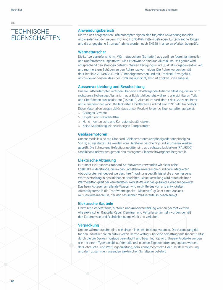
Anwendungsbereich Die von uns hergestellten Luftverdampfer eignen sich für jeden Anwendungsbereich und werden mit den neuen HFC- und HCFC-Kühlmitteln betrieben. Luftschläuche, Bögen und die angegebene Stromaufnahme wurden nach EN328 in unseren Werken überprüft.
WärmetauscherDie Luftverdampfer sind mit Wärmetauschern (Batterien) aus gerillten Aluminiumlamellen und Kupferrohren ausgestattet. Die Seitenwände sind aus Aluminium. Das ganze wird entsprechend den strengen betriebsinternen Fertigungs- und Qualitätsvorgaben entwickelt und montiert, um Schäden an den Rohren zu vermeiden. Die Rohre werden gemäß der Richtlinie 2014/68/UE mit 33 Bar abgenommen und mit Trockenluft vorgefüllt, um zu gewährleisten, dass der Kühlkreislauf dicht, absolut trocken und sauber ist.
Aussenverkleidung und BeschichtungUnsere Luftverdampfer verfügen über eine selbsttragende Außenverkleidung, die an nicht sichtbaren Stellen aus Aluminium oder Edelstahl besteht, während alle sichtbaren Teile und Oberflächen aus lackiertem (RAL9010) Aluminium sind, damit das Ganze sauberer und einnehmender wirkt. Die lackierten Oberflächen sind mit einem Schutzfilm bedeckt.Diese Materialien sorgen dafür, dass unser Produkt folgende Eigenschaften aufweist: ØØ Geringes GewichtØØ Ungiftig und schadstofffreiØØ Hohe mechanische und KorrosionsbeständigkeitØØ Keine Kaltbrüchigkeit bei niedrigen Temperaturen.
GebläsemotorenUnsere Modelle sind mit Standard-Gebläsemotoren (einphasig oder dreiphasig zu 50 Hz) ausgestattet. Sie werden vom Hersteller bescheinigt und in unseren Werken geprüft. Die Schutz-und Befestigungsgitter sind aus schwarz lackiertem (RAL9005) Stahlblech und werden gemäß den strengsten Sicherheitsvorgaben hergestellt.
Elektrische AbtauungFür unser elektrisches Standard-Abtausystem verwenden wir elektrische Edelstahl-Widerstände, die im den Lamellenwärmetauscher und dem integrierten Abtropfsystem eingebaut werden. Ihre Anordnung gewährleistet die angemessene Wärmeverteilung in den kritischen Bereichen. Diese Verteilung wird durch die hohe Wärmeleitfähigkeit der verwendeten Werkstoffe auf das gesamte Gerät ausgeweitet. Das beim Abtauen anfallende Wasser wird mit Hilfe des von uns entwickelten Abtropfsystems in die Tropfwanne geleitet. Diese verfügt über einen Auslass mit Gewindeanschluss, der den natürlichen Wasserabfluss beschleunigt.
Elektrische Bauteile Elektrische Widerstände, Motoren und Außenverkleidung können geerdet werden. Alle elektrischen Bauteile, Kabel, Klemmen und Verteilerschachteln wurden gemäß den Euronormen und Richtlinien ausgewählt und verkabelt.
VerpackungUnsere Wärmetauscher sind alle einzeln in einer Holzkiste verpackt. Die Verpackung der für den Industriebereich entwickelten Geräte verfügt über eine selbsttragende Innenstruktur, durch die die Deckenmontage vereinfacht und beschleunigt wird. Unsere Produkte werden alle mit einem Typenschild, auf dem die technischen Eigenschaften angegeben werden, der Gebrauchs- und Wartungsanleitung, dem Abnahmeprotokoll, der Herstellererklärung und dem zusammenfassenden elektrischen Schaltplan geliefert.
DE
TECHNISCHE EIGENSCHAFTEN

09
Unit coolers and brine units
Applications Les évaporateurs ventilés que nous produisons sont adaptés à n’importe quelle application avec tous les nouveaux réfrigérants HFC et HCFC. Les débits d’air, les flèches d’air et les absorptions électriques déclarées ont été vérifiées selon les normes EN328 dans nos usines.
Les batteriesLes évaporateurs ventilés sont construits avec des échangeurs de chaleur (batteries), réalisés avec des ailettes ondulées en aluminium et des tubes en cuivre. Les plaques d’appui sont réalisées en aluminium. Le tout est conçu et assemblé en respectant les spécifications rigoureuses de l’entreprise en matière de production et de qualité, afin d’éviter d’endommager les tubulures. Elles sont testées à 33 bars, conformément aux prescriptions de la Directive 2014/68/UE, et préchargées à l’air sec pour garantir l’étanchéité, l’absence d’humidité et la propreté du circuit frigorifique.
Carrosserie et finitionsNos évaporateurs ventilés sont construits avec une carrosserie autoportante en aluminium ou acier inox, dans les parties non visibles, et en aluminium prélaqué RAL9010 pour toutes les parties ou finitions apparentes, de manière à obtenir un appareil plus propre et plus esthétique. Les appareils sont fournis avec les surfaces prélaquées entièrement revêtues d’une pellicule plastique de protection. Ces matériaux assurent à nos produits : ØØ un poids limitéØØ des surfaces atoxiques et sans particules polluantesØØ une haute résistance mécanique et à la corrosionØØ l’absence de fragilité aux basses températures.
Les motoventilateursNos modèles sont équipés de motoventilateurs standard, monophasés ou triphasés à 50 Hz. Ils sont certifiés par le producteur et testés dans nos usines. Les grilles de protection et de fixation sont en acier laqué noir RAL9005 et sont construites en respectant les normes de sécurité les plus rigoureuses.
Le dégivrage électriqueNotre système de dégivrage électrique standard est réalisé en utilisant des résistances électriques en acier inox insérées à l’intérieur du faisceau d’ailettes et sur les égouttoirs internes.Elles sont disposées de manière à garantir la distribution de la chaleur à l’intérieur de l’appareil en tenant compte des zones les plus critiques. Le haut degré de conductivité thermique des matériaux employés garantit la distribution de la chaleur dans tout l’appareil. Toute l’eau dérivant du dégivrage est acheminée par l’égouttoir de notre conception, dans le bac collecteur, muni d’un raccord fileté pour le drainage afin de favoriser l’évacuation naturelle de l’eau.
Les composants électriquesLes résistances électriques, les moteurs et la carcasse sont prévus pour la mise à la terre. Tous les composants électriques, les câbles, les serres-câbles et les boîtes de dérivation sont sélectionnés et câblés en respectant les directives et les normes communautaires.
L’emballageTous nos échangeurs sont emballés individuellement dans une cage entièrement en bois. Pour les modèles de type industriel, l’emballage est muni d’une structure interne autoportante étudiée pour faciliter l’installation au plafond et la rendre plus rapide. Tous nos produits sont munis d’une étiquette avec les caractéristiques techniques, d’un manuel pour l’utilisation et la maintenance, d’un certificat d’essai, de la déclaration du fabricant et d’un schéma récapitulatif des connexions électriques.
FR
CARACTÉRISTIQUES GÉNÉRALES
Roen Est Heat exchangers and more
10
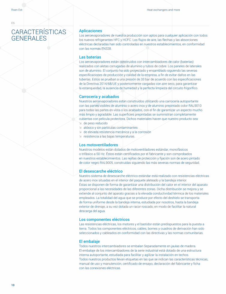
Aplicaciones Los aeroevaporadores de nuestra producción son aptos para cualquier aplicación con todos los nuevos refrigerantes HFC y HCFC. Los flujos de aire, las flechas y las absorciones eléctricas declaradas han sido controladas en nuestros establecimientos, en conformidad con las normas EN328.
Las bateríasLos aeroevaporadores están construidos con intercambiadores de calor (baterías) realizados con aletas corrugadas de aluminio y tubos de cobre. Los paneles de laterales son de aluminio. El conjunto ha sido proyectado y ensamblado siguiendo las severas especificaciones de producción y calidad de la empresa, a fin de evitar daños en las tuberías. Estos se prueban a una presión de 33 bar de acuerdo con las especificaciones de la Directiva 2014/68/UE y posteriormente cargadas con aire seco, para garantizar la estanqueidad, la ausencia de humedad y la perfecta limpieza del circuito frigorífico.
Carrocería y acabadosNuestros aeroevaporadores están construidos utilizando una carrocería autoportante con las partes visibles de aluminio o acero inox y de aluminio prepintado color RAL9010 para todas las partes en vista o los acabados, con el fin de garantizar un aspecto mucho más limpio y agradable. Las superficies prepintadas se suministran completamente cubiertas con película protectora. Dichos materiales hacen que nuestro producto sea:ØØ de peso reducidoØØ atóxico y sin partículas contaminantesØØ de elevada resistencia mecánica y a la corrosiónØØ resistencia a las bajas temperaturas.
Los motoventiladoresNuestros modelos están dotados de motoventiladores estándar, monofásicos o trifásico a 50 Hz. Éstos están certificados por el fabricante y son comprobados en nuestros establecimientos. Las rejillas de protección y fijación son de acero pintado de color negro RAL9005, construidas siguiendo las más severas normas de seguridad.
El desescarche eléctricoNuestro sistema de desescarche eléctrico estándar está realizado con resistencias eléctricas de acero inox situadas en el interior del paquete aleteado y la bandeja interior. Éstas se disponen de forma de garantizar una distribución del calor en el interior del aparato proporcional a las necesidades de las diferentes zonas. Dicha distribución se mejora y se extiende al conjunto del aparato gracias a la elevada conductividad térmica de los materiales empleados. La totalidad del agua que se produce por efecto del deshielo se transporta de forma uniforme desde la bandeja interna, estudiada por nosotros, hasta la bandeja exterior de drenaje, a su vez dotada un racor roscado, en modo de facilitar la natural descarga del agua.
Los componentes eléctricosLas resistencias eléctricas, los motores y el bastidor están predispuestos para la puesta a tierra. Todos los componentes eléctricos, cables, bornes y cuadros de derivación han sido seleccionados y cableados en conformidad con las directivas y las normas comunitarias.
El embalajeTodos nuestros intercambiadores se embalan Separadamente en jaulas de madera. El embalaje de los intercambiadores de la serie industrial está dotado de una estructura interna autoportante, estudiada para facilitar y agilizar la instalación en techos. Todos nuestros productos llevan etiquetas en las que se indican las características técnicas, manual de uso y manutención, certificado de ensayo, declaración del fabricante y ficha con las conexiones eléctricas.
ES
CARACTERÍSTICAS GENERALES

11
Unit coolers and brine units
Сферы примененияВоздухоохладители производства Roen Est могут применяться в любых сферах со всеми новыми хладагентами HFC и HCFC. Заявленные значения расхода воздуха, дальнобойности воздушной струи и потребления электроэнергии были проверены в соответствии с нормами EN328 на предприятиях компании.
БатареиДля производства воздухоохладителей используются теплообменники (батареи) с гофрированными алюминиевыми ребрами и медными трубами. Опорные пластины производятся из алюминия. Проектирование и сборка изделий осуществляются в соответствии со строгими спецификациями производства и качества компании, чтобы избежать повреждения трубопроводов. Изделия испытываются под давлением 33 бар согласно требованиям Директивы 2014/68/UE и заправляются сухим воздухом для обеспечения герметичности, отсутствия влаги и идеальной чистоты холодильного контура.
Корпус и отделкаВоздухоохладители Roen Est имеют корпус с самонесущей конструкцией из алюминия или нержавеющей стали в невидимых местах. Внешние части корпуса изготовлены из алюминия, окрашенного в цвет RAL9010, что придает всему узлу чистый и приятный вид. Агрегаты поставляются с окрашенными поверхностями, полностью покрытыми защитной пленкой. Такие материалы придают изделию следующие характеристики: ØØ небольшой весØØ нетоксичность и отсутствие загрязняющих частицØØ высокую механическую прочность и коррозионную стойкостьØØ отсутствие хрупкости при низких температурах.
ВентиляторыИзделия Roen Est комплектуются стандартными вентиляторами с однофазными или трехфазными двигателями с частотой 50 Гц. Они сертифицируются производителем и тестируются на предприятиях компании. Защитные крепежные решетки изготовлены из стали, окрашенной в черный цвет RAL9005, согласно самым строгим нормам безопасности.
Электрическое оттаиваниеНаша стандартная система электрического оттаивания состоит из электрических нагревательных элементов, изготовленных из нержавеющей стали, которые установлены внутри оребренного трубного пучка и на внутренних каплеуловителях. Их расположение обеспечивает распределение тепла внутри изделия пропорционально критичности различных зон. Тепло распределяется по всему прибору благодаря высокой теплопроводности используемых материалов. Вся вода, образующаяся при оттаивании, равномерно отводится из специально спроектированного каплеуловителя в поддон, оборудованный резьбовым соединением, что способствует естественному стоку воды.
Электрические компоненты Электрические нагревательные элементы, двигатели и корпус подготовлены для заземления. Все электрические компоненты, кабели, клеммы и распределительные коробки подобраны и соединены кабельной проводкой в соответствии с директивами и нормами ЕС.
УпаковкаВсе теплообменники упаковываются по отдельности в деревянные контейнеры. Упаковка для теплообменников промышленной серии предполагает самонесущую внутреннюю конструкцию, разработанную для облегчения и ускорения потолочной установки. Все теплообменники оснащаются этикеткой с техническими характеристиками, руководством по эксплуатации и техническому обслуживанию, свидетельством о приемочных испытаниях, декларацией изготовителя и сводной схемой электрических соединений.
RU
ОБЩИЕ ХАРАКТЕРИСТИКИ

Roen Est Heat exchangers and more
12

13
Unit coolers and brine units

Roen Est Heat exchangers and more
14
SMALL UNIT COOLERS200 / 250 / 315 SD Series
EN
ØØ Available fan motor diameters: 200 mm, 250 mm, and 315 mmØØ Available number of fan motors:
200 mm, 250 mm from 1 to 4 motors, 315 mm from 1 to 5 fan motorsØØ Available fin spacing:
¬ with fan motor 200 mm, 4/8 mm differentiated and 6 mm ¬ with fan motor 250 mm, 4 mm and 6 mm ¬ with fan motor 315 mm, 3 mm, 4.5 mm and 6 mm
ØØ Fan motor voltage: 230V / 1 / 50HzØØ Fan motor protection class:
¬ diameter 200 mm, 250 mm - IP42 ¬ diameter 315 mm - IP44
IT
ØØ Diametri motore disponibili: 200 mm, 250 mm e 315 mmØØ Numero motori disponibile:
200 mm, 250 mm da 1 a 4 motori, 315 mm da 1 a 5 motoriØØ Passi alette disponibili:
¬ con motore 200 mm, 4/8 mm differenziato e 6 mm ¬ con motore 250 mm, 4 mm e 6 mm ¬ con motore 315 mm, 3 mm, 4,5 mm e 6 mm
ØØ Tensione motori: 230 V / 1 / 50 HzØØ Grado di protezione motori:
¬ diametro 200 mm e 250 mm - IP42 ¬ diametro 315 mm - IP44
DE
ØØ Verfügbare Motordurchmesser: 200 mm, 250 mm und 315 mmØØ Verfügbare Motorenanzahl:
200 mm, 250 mm mit 1 bis 4 Motoren, 315 mm von 1 bis 5 motorenØØ Abstand der lamellen:
¬ mit Motor 200 mm, 4/8 mm versetzt und 6 mm ¬ mit Motor 250 mm, 4 mm und 6 mm ¬ mit Motor 315 mm, 3 mm, 4,5 mm und 6 mm
ØØ Motorspannung: 230 V / 1 / 50 HzØØ Schutzart der Motoren:
¬ Durchmesser 200 mm, 250 mm - IP42 ¬ Durchmesser 315 mm - IP44
CERTIFIED RANGE
Slanted unit coolers 250Aeroevaporatori angolari 250Eckverdampfer 250
Évaporateurs ventilés angulaires 250Aeroevaporadores angulares 250Угловые воздухоохладители 250

15
Unit coolers and brine units
FR
ØØ Diamètres moteur disponibles : 200 mm, 250 mm et 315 mmØØ Nombre de moteurs disponible :
200 mm, 250 mm de 1 à 4 moteurs, 315 mm de 1 à 5 moteursØØ Pas ailettes disponibles :
¬ avec moteur 200 mm, 4/8 mm différencié et 6 mm ¬ avec moteur 250 mm, 4 mm et 6 mm ¬ avec moteur 315 mm, 3 mm, 4,5 mm et 6 mm
ØØ Tension moteurs : 230 V / 1 / 50 HzØØ Indice de protection moteurs :
¬ diamètre 200 mm, 250 mm - IP42 ¬ diamètre 315 mm - IP44
ES
ØØ Diámetros motor disponibles: 200 mm, 250 mm y 315 mmØØ Número motores disponible:
200 mm, 250 mm de 1 a 4 motores, 315 mm de 1 a 5 motoresØØ Pasos de aleta disponibles:
¬ con motor 200 mm, 4/8 mm diferenciado y 6 mm ¬ con motor 250 mm, 4 mm y 6 mm ¬ con motor 315 mm 3 mm, 4,5 mm y 6 mm
ØØ Tensión motores: 230 V / 1 / 50HzØØ Grado de protección motores:
¬ diámetro 200 mm, 250 mm - IP42 ¬ diámetro 315 mm - IP44
RU
ØØ Диаметр двигателя: 200 мм, 250 мм и 315 ммØØ Количество двигателей:
200 мм, 250 мм от 1 до 4 двигателей, 315 мм от 1 до 5 двигателейØØ Шаг ребер:
¬ с двигателем 200 мм, 4/8 мм дифференцированный и 6 мм ¬ с двигателем 250 мм, 4 мм и 6 мм ¬ с двигателем 315 мм, 3 мм, 4,5 мм и 6 мм
ØØ Напряжение двигателей: 230 В / 1 / 50 ГцØØ Степень защиты двигателей:
¬ Диаметр 200 мм, 250 мм - IP42 ¬ Диаметр 315 мм - IP44
Aeroevaporatori angolariEckverdampfer
Évaporateurs ventilés angulairesAeroevaporadores angulares
Угловые воздухоохладители

A
E
C
A
E
C
A
E
C
A
E
C
= =
=
B
D
==
==
=
Roen Est Heat exchangers and more
16
SD.22
Code Motor Diam. Ø [mm] Supply line Fan Speed [RPM] Power [W] Current [A] dB(A) 5 meter
- 4M 4 poles 200 230/1/50 1300 36 0.46 43
MODELFan motors
N°
Dimensions ConnectionsØ
drainA B C D E IN OUT
mm
SD.x.22.1.04/06 1 410 440 125 200 300 9.52 9.52 ¾"
SD.x.22.1.08/12 1 610 440 125 200 500 9.52 9.52 ¾"
SD.x.22.2.04/06 2 610 440 125 200 500 9.52 9.52 ¾"
SD.x.22.2.08/12 2 860 440 125 200 2x375 9.52 9.52 ¾"
SD.x.22.3.xx 3 1110 440 125 200 2x500 12 16 ¾"
SD.x.22.4.xx 4 1360 440 125 200 3x410 12 16 ¾"
TUBESØ7
OLD
NEW
Reduced tube diameter

17
Unit coolers and brine units
MODELCa
paci
ty S
C2
Air fl
ow
Air t
hrow
Surf
ace
Tube
vol
ume
Elec
tric
def
rost
Fan
mot
ors
Fan
diam
eter
Soun
d pr
essu
rele
vel -
5 m
Pow
er
Curr
ent a
bsor
btio
n
Wei
ght
kW m3/h m m2 dm3 kW n mm dBA 5m W A kg
H Type
Fin spacing 4 mm
SD.H.22.1.04-4M 0,35 210 2,3 1,63 0,20 0,40 1 200 43 36 0,25 4.7
SD.H.22.1.06-4M 0,42 185 1,9 2,45 0,30 0,40 1 200 43 36 0,25 5.2
SD.H.22.1.08-4M 0,53 265 2,3 2,72 0,32 0,60 1 200 43 36 0,25 5.9
SD.H.22.1.12-4M 0,63 235 2,1 4,08 0,48 0,60 1 200 43 36 0,25 6.9
SD.H.22.2.04-4M 0,69 365 3,1 2,72 0,32 0,60 2 200 46 72 0,50 7.9
SD.H.22.2.06-4M 0,80 325 2,5 4,08 0,48 0,60 2 200 46 72 0,50 8.7
SD.H.22.2.08-4M 0,96 475 3,2 4,08 0,48 0,90 2 200 46 72 0,50 9.3
SD.H.22.2.12-4M 1,07 435 2,8 6,13 0,72 0,90 2 200 46 72 0,50 10.4
SD.H.22.3.04-4M 1,25 645 4,0 5,45 0,64 1,10 3 200 48 108 0,75 12.8
SD.H.22.3.06-4M 1,47 570 3,3 8,17 0,96 1,10 3 200 48 108 0,75 14.2
SD.H.22.4.04-4M 1,63 820 4,6 6,70 0,78 1,30 4 200 49 108 1,00 16.2
SD.H.22.4.06-4M 1,77 710 3,9 10,05 1,17 1,30 4 200 49 108 1,00 18
M Type
Fin spacing 6 mm
SD.M.22.1.04-4M 0,30 235 2,5 1,14 0,20 0,40 1 200 43 36 0,25 4.5
SD.M.22.1.06-4M 0,37 205 2,1 1,70 0,30 0,40 1 200 43 36 0,25 5.1
SD.M.22.1.08-4M 0,46 285 2,5 1,89 0,32 0,60 1 200 43 36 0,25 5.7
SD.M.22.1.12-4M 0,55 250 2,3 2,84 0,48 0,60 1 200 43 36 0,25 6.7
SD.M.22.2.04-4M 0,60 400 3,3 1,89 0,32 0,60 2 200 46 72 0,50 7.6
SD.M.22.2.06-4M 0,71 350 2,7 2,84 0,48 0,60 2 200 46 72 0,50 8.4
SD.M.22.2.08-4M 0,88 520 3,4 2,84 0,48 0,90 2 200 46 72 0,50 9
SD.M.22.2.12-4M 0,95 470 3,0 4,26 0,72 0,90 2 200 46 72 0,50 10.1
SD.M.22.3.04-4M 1,10 690 4,2 3,79 0,64 1,10 3 200 48 108 0,75 12.3
SD.M.22.3.06-4M 1,34 630 3,5 5,68 0,96 1,10 3 200 48 108 0,75 13.7
SD.M.22.4.04-4M 1,46 870 4,8 4,66 0,78 1,30 4 200 49 108 1,00 15.5
SD.M.22.4.06-4M 1,65 770 4,1 6,99 1,17 1,30 4 200 49 108 1,00 17.2
SD.22

A
E
C
A
E
C
A
E
C
A
E
C
==
= =
==
= = DB
Roen Est Heat exchangers and more
18
Code Motor Diam. Ø [mm] Supply line Fan Speed [RPM] Power [W] Current [A] dB(A) 5 meter
- 4M 4 poles 250 230/1/50 1300 73 0.52 39
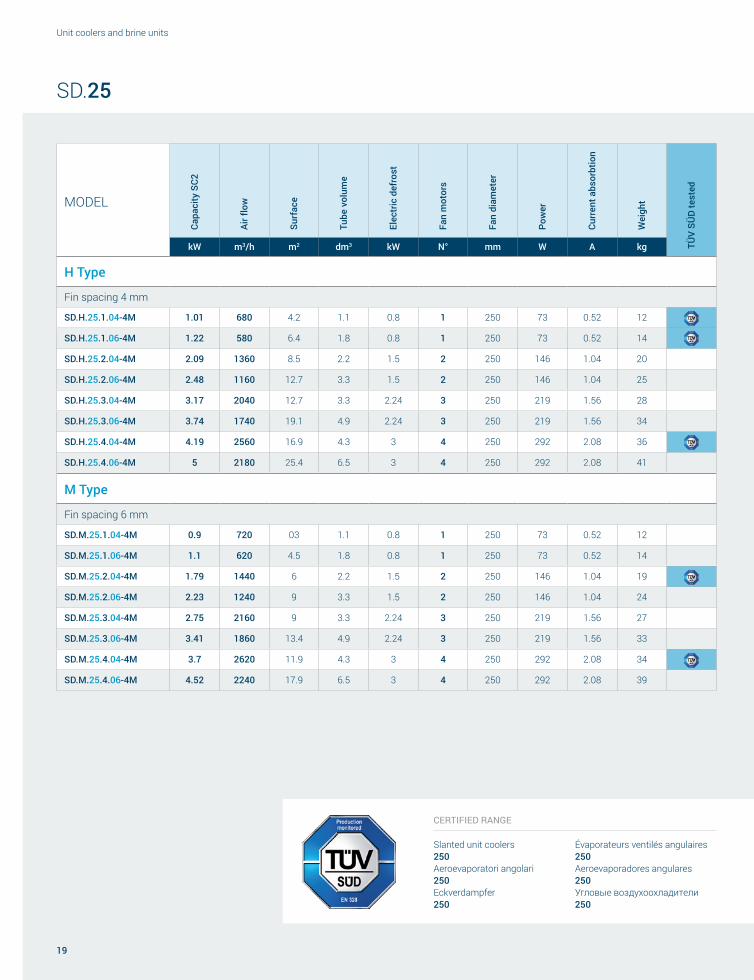
SD.25
MODELFan motors
N°
Dimensions ConnectionsØ
drainA B C D E IN OUT
mm
SD.x.25.1.xx 1 810 610 230 640 515 12 16 ¾"
SD.x.25.2.xx 2 1310 610 230 640 1015 12 16 ¾"
SD.x.25.3.xx 3 1810 610 230 640 1515 16 22 ¾"
SD.x.25.4.xx 4 2310 610 230 640 1015+1000 16 22 ¾"
CERTIFIED RANGE
Slanted unit coolers 250Aeroevaporatori angolari 250Eckverdampfer 250Évaporateurs ventilés angulaires 250Aeroevaporadores angulares 250Угловые воздухоохладители 250
TUBES
Ø9,52
M Type
Fin spacing 6 mm
SD.M.25.1.04-4M 0.9 720 03 1.1 0.8 1 250 73 0.52 12
SD.M.25.1.06-4M 1.1 620 4.5 1.8 0.8 1 250 73 0.52 14
SD.M.25.2.04-4M 1.79 1440 6 2.2 1.5 2 250 146 1.04 19
SD.M.25.2.06-4M 2.23 1240 9 3.3 1.5 2 250 146 1.04 24
SD.M.25.3.04-4M 2.75 2160 9 3.3 2.24 3 250 219 1.56 27
SD.M.25.3.06-4M 3.41 1860 13.4 4.9 2.24 3 250 219 1.56 33
SD.M.25.4.04-4M 3.7 2620 11.9 4.3 3 4 250 292 2.08 34
SD.M.25.4.06-4M 4.52 2240 17.9 6.5 3 4 250 292 2.08 39
19
Unit coolers and brine units
SD.25
CERTIFIED RANGE
Slanted unit coolers 250Aeroevaporatori angolari 250Eckverdampfer 250
Évaporateurs ventilés angulaires 250Aeroevaporadores angulares 250Угловые воздухоохладители 250
MODELCa
paci
ty S
C2
Air fl
ow
Surf
ace
Tube
vol
ume
Elec
tric
def
rost
Fan
mot
ors
Fan
diam
eter
Pow
er
Curr
ent a
bsor
btio
n
Wei
ght
TÜV
SÜD
test
ed
kW m3/h m2 dm3 kW N° mm W A kg
H Type
Fin spacing 4 mm
SD.H.25.1.04-4M 1.01 680 4.2 1.1 0.8 1 250 73 0.52 12
SD.H.25.1.06-4M 1.22 580 6.4 1.8 0.8 1 250 73 0.52 14
SD.H.25.2.04-4M 2.09 1360 8.5 2.2 1.5 2 250 146 1.04 20
SD.H.25.2.06-4M 2.48 1160 12.7 3.3 1.5 2 250 146 1.04 25
SD.H.25.3.04-4M 3.17 2040 12.7 3.3 2.24 3 250 219 1.56 28
SD.H.25.3.06-4M 3.74 1740 19.1 4.9 2.24 3 250 219 1.56 34
SD.H.25.4.04-4M 4.19 2560 16.9 4.3 3 4 250 292 2.08 36
SD.H.25.4.06-4M 5 2180 25.4 6.5 3 4 250 292 2.08 41

A
E
C
A
E
C
A
E
C
A
E
C
==
= =
==
= = DB
Roen Est Heat exchangers and more
20
Code Motor Diam. Ø [mm] Supply line Fan Speed [RPM] Power [W] Current [A] dB(A) 5 meter
- 4M 4 poles 250 230/1/50 1300 60 0.42 44
SD.26
MODELFan motors
N°
Dimensions ConnectionsØ
drainA B C D E IN OUT
mm
SD.x.26.1.xx 1 810 610 230 640 515 12 16 ¾"
SD.x.26.2.xx 2 1310 610 230 640 1015 12 16 ¾"
SD.x.26.3.xx 3 1810 610 230 640 1515 16 22 ¾"
SD.x.26.4.xx 4 2310 610 230 640 1015+1000 16 22 ¾"
TUBES
Ø7,94
OLD
NEW
Reduced tube diameter

21
Unit coolers and brine units
SD.26
MODELCa
paci
ty S
C2
Capa
city
SC4
Air fl
ow
Air t
hrow
Surf
ace
Tube
vol
ume
Elec
tric
def
rost
Fan
mot
ors
Fan
diam
eter
Soun
d pr
essu
re
leve
l - 5
m
Pow
er
cons
umpt
ion
Curr
ent
cons
umpt
ion
Wei
ght
kW kW m3/h m m2 dm3 kW N° mm dB(A) W A kg
H Type
Fin spacing 4 mm
SD.H.26.1.04-4M 1,00 - 640 3,9 4,3 0,8 0.6 1 250 44 60 0,42 12
SD.H.26.1.06-4M 1,21 - 545 3,2 6,5 1,2 0,6 1 250 44 60 0,42 14
SD.H.26.2.04-4M 2,07 - 1280 5,5 8,6 1,6 1,2 2 250 47 120 0,84 20
SD.H.26.2.06-4M 2,46 - 1090 4,5 13,0 2,4 1,2 2 250 47 120 0,84 25
SD.H.26.3.04-4M 3,14 - 1900 6,7 12,9 2,4 1,8 3 250 49 180 1,26 28
SD.H.26.3.06-4M 3,70 - 1640 5,5 19,5 3,6 1,8 3 250 49 180 1,26 34
SD.H.26.4.04-4M 4,15 - 2450 7,8 17,2 3,2 2,4 4 250 50 240 1,68 36
SD.H.26.4.06-4M 4,95 - 2040 6,4 26,0 4,8 2,4 4 250 50 240 1,68 41
M Type
Fin spacing 6 mm
SD.M.26.1.04-4M 0,89 0,56 680 4,1 3,3 0,8 0.6 1 250 44 60 0,42 12
SD.M.26.1.06-4M 1,09 0,67 580 3,5 5,0 1,2 0,6 1 250 44 60 0,42 14
SD.M.26.2.04-4M 1,77 1,12 1350 5,8 6,6 1,6 1,2 2 250 47 120 0,84 19
SD.M.26.2.06-4M 2,21 1,34 1150 4,9 10,0 2,4 1,2 2 250 47 120 0,84 24
SD.M.26.3.04-4M 2,72 1,68 2030 7,1 9,9 2,4 1,8 3 250 49 180 1,26 27
SD.M.26.3.06-4M 3,38 2,01 1750 6,1 15,0 3,6 1,8 3 250 49 180 1,26 33
SD.M.26.4.04-4M 3,66 2,24 2550 8,2 13,2 3,2 2,4 4 250 50 240 1,68 34
SD.M.26.4.06-4M 4,47 2,68 2200 7,0 20,0 4,8 2,4 4 250 50 240 1,68 39

A
= =Ø
C
E D
B
Roen Est Heat exchangers and more
22
Code Motor Diam. Ø [mm] Supply line Fan Speed [RPM] Power [W] Current [A] dB(A) 5 meter
- 4M 4 poles 315 230/1/50 1370 95 0.42 52
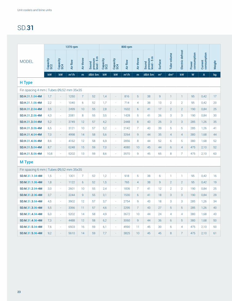
SD.31
MODELFan motors
N°
Dimensions ConnectionsØ
drainA B C D E IN OUT
mm
SD.x.31.1.xx 1 1020 715 300 750 630 12 12 1”
SD.x.31.2.xx 2 1620 715 300 750 1230 12 22 1”
SD.x.31.3.xx 3 2220 715 300 750 1830 12 22 1”
SD.x.31.4.xx 4 2820 715 300 750 2x1215 12 22 1”
SD.x.31.5.xx 5 3420 715 300 750 2x1515 16 28 1”-¼
23
Unit coolers and brine units
SD.31
MODEL
1370 rpm 800 rpmCa
paci
ty
SC2
Capa
city
SC
4
Air fl
ow
Air t
hrow
Soun
d pr
essu
rele
vel -
5 m
Capa
city
SC
2
Capa
city
SC
4
Air fl
ow
Air t
hrow
Soun
d pr
essu
rele
vel -
5 m
Surf
ace
Tube
vol
ume
Elec
tric
def
rost
Pow
er
cons
umpt
ion
Curr
ent
cons
umpt
ion
Wei
ght
kW kW m3/h m dBA 5m kW kW m3/h m dBA 5m m2 dm3 kW W A kg
H Type
Fin spacing 4 mm | Tubes Ø9,52 mm 35x35
SD.H.31.1.04-4M 1,7 - 1250 7 52 1,4 - 816 5 38 9 1 1 95 0,42 17
SD.H.31.1.06-4M 2,2 - 1040 6 52 1,7 - 714 4 38 13 2 2 95 0,42 20
SD.H.31.2.04-4M 3,5 - 2499 10 55 2,8 - 1632 6 41 17 2 2 190 0,84 25
SD.H.31.2.06-4M 4,3 - 2081 8 55 3,5 - 1428 5 41 26 3 3 190 0,84 30
SD.H.31.3.04-4M 5,2 - 3749 12 57 4,2 - 2448 8 43 26 3 3 285 1,26 35
SD.H.31.3.06-4M 6,5 - 3121 10 57 5,2 - 2142 7 43 39 5 5 285 1,26 41
SD.H.31.4.04-4M 7,0 - 4998 14 58 5,6 - 3264 9 44 35 4 4 380 1,68 44
SD.H.31.4.06-4M 8,6 - 4162 12 58 6,9 - 2856 8 44 52 6 5 380 1,68 52
SD.H.31.5.04-4M 8,7 - 6248 15 59 7,0 - 4080 10 45 44 6 4 475 2,10 52
SD.H.31.5.06-4M 10,8 - 5202 13 59 8,6 - 3570 9 45 65 8 7 475 2,10 63
M Type
Fin spacing 6 mm | Tubes Ø9,52 mm 35x35
SD.M.31.1.04-4M 1,5 - 1301 7 52 1,2 - 918 5 38 6 1 1 95 0,42 16
SD.M.31.1.06-4M 1,8 - 1122 6 52 1,5 - 765 4 38 9 2 2 95 0,42 19
SD.M.31.2.04-4M 3,0 - 2601 10 55 2,4 - 1836 7 41 12 2 2 190 0,84 25
SD.M.31.2.06-4M 3,7 - 2244 9 55 3,1 - 1530 6 41 18 3 3 190 0,84 29
SD.M.31.3.04-4M 4,5 - 3902 12 57 3,7 - 2754 9 43 18 3 3 285 1,26 34
SD.M.31.3.06-4M 5,5 - 3366 11 57 4,6 - 2295 7 43 27 5 5 285 1,26 40
SD.M.31.4.04-4M 6,0 - 5202 14 58 4,9 - 3672 10 44 24 4 4 380 1,68 43
SD.M.31.4.06-4M 7,3 - 4488 12 58 6,2 - 3060 9 44 36 6 5 380 1,68 50
SD.M.31.5.04-4M 7,6 - 6503 16 59 6,1 - 4590 11 45 30 6 4 475 2,10 50
SD.M.31.5.06-4M 9,2 - 5610 14 59 7,7 - 3825 10 45 45 8 7 475 2,10 61

Roen Est Heat exchangers and more
24
SD.31
MODEL
1370 rpm 800 rpm
Capa
city
SC
2
Capa
city
SC
4
Air fl
ow
Air t
hrow
Soun
d pr
essu
rele
vel -
5 m
Capa
city
SC
2
Capa
city
SC
4
Air fl
ow
Air t
hrow
Soun
d pr
essu
rele
vel -
5 m
Surf
ace
Tube
vol
ume
Elec
tric
def
rost
Pow
er
cons
umpt
ion
Curr
ent
cons
umpt
ion
Wei
ght
kW kW m3/h m dBA 5m kW kW m3/h m dBA 5m m2 dm3 kW W A kg
L Type
Fin spacing 8 mm | Tubes Ø9,52 mm 35x35
SD.L.31.1.04-4M 1,4 0,9 1346 8 52 1,1 0,7 938 5 38 5 1 1 95 0,42 16
SD.L.31.1.06-4M 1,7 1,1 1183 7 52 1,4 0,9 816 5 38 7 2 2 95 0,42 19
SD.L.31.2.04-4M 2,7 1,7 2693 11 55 2,3 1,4 1877 7 41 9 2 2 190 0,84 25
SD.L.31.2.06-4M 3,3 2,2 2366 9 55 2,8 1,7 1632 6 41 14 3 3 190 0,84 29
SD.L.31.3.04-4M 4,1 2,6 4039 13 57 3,4 2,0 2815 9 43 14 3 3 285 1,26 34
SD.L.31.3.06-4M 5,0 3,3 3550 11 57 4,2 2,6 2448 8 43 21 5 5 285 1,26 40
SD.L.31.4.04-4M 5,4 3,5 5386 15 58 4,5 2,7 3754 10 44 18 4 4 380 1,68 43
SD.L.31.4.06-4M 6,7 4,4 4733 13 58 5,6 3,5 3264 9 44 28 6 5 380 1,68 50
SD.L.31.5.04-4M 6,8 4,4 6732 17 59 5,7 3,4 4692 12 45 23 6 4 475 2,10 50
SD.L.31.5.06-4M 8,4 5,5 5916 15 59 7,0 4,3 4080 10 45 35 8 7 475 2,10 61
V Type
Fin spacing 10 mm | Tubes Ø12 mm 35x35
SD.V.31.1.04-4M 1,3 0,8 1306 7 52 1,2 0,7 877 5 38 4 2 1 95 0,42 15
SD.V.31.1.06-4M 1,6 1,1 1142 6 52 1,5 0,9 745 4 38 6 2 2 95 0,42 18
SD.V.31.2.04-4M 2,6 1,5 2611 10 55 2,3 1,4 1754 7 41 8 3 2 190 0,84 24
SD.V.31.2.06-4M 3,2 2,3 2285 9 55 3,0 1,8 1489 6 41 11 5 3 190 0,84 28
SD.V.31.3.04-4M 3,9 2,3 3917 12 57 3,5 2,2 2632 8 43 11 5 3 285 1,26 33
SD.V.31.3.06-4M 4,8 3,4 3427 11 57 4,4 2,7 2234 7 43 17 7 5 285 1,26 39
SD.V.31.4.04-4M 5,2 3,0 5222 14 58 4,6 2,9 3509 10 44 15 6 4 380 1,68 42
SD.V.31.4.06-4M 6,4 4,5 4570 12 58 5,9 3,6 2978 8 44 22 10 5 380 1,68 49
SD.V.31.5.04-4M 6,5 3,8 6528 16 59 5,8 3,6 4386 11 45 19 8 4 475 2,10 49
SD.V.31.5.06-4M 8,0 5,7 5712 14 59 7,4 4,5 3723 9 45 28 12 7 475 2,10 60

25
Unit coolers and brine units

Roen Est Heat exchangers and more
26
DOUBLE FLOW UNIT COOLERS250 / 350 / 500 DD Series
EN
ØØ Available fan motor diameters: 250 mm, 350 mm and 500 mmØØ Available number of fan motors:
from 1 to 5 fan motorsØØ Available fin spacing:
¬ fan motor diameter 250 mm and 350 mm: 3 mm, 4.5 mm and 6 mm ¬ fan motor diameter: 500 mm, 4 mm, 6 mm, 8 mm, 10 mm and 12 mm
ØØ Fan motor voltage: ¬ 230V / 1 / 50Hz for diameters 250 mm and 350 mm ¬ 400V / 3 / 50Hz for diameter 500 mm
ØØ Fan motor protection class: ¬ diameter 250 mm - IP42 ¬ diameter 350 mm - IP44 ¬ diameter 500 mm - IP54
IT
ØØ Diametri motore disponibili: 250 mm, 350 mm e 500 mmØØ Numero motori disponibile:
da 1 a 5 motoriØØ Passi alette disponibili:
¬ diametro motore 250 mm e 350 mm: 3 mm, 4,5 mm e 6 mm ¬ diametro motore: 500 mm, 4 mm, 6 mm, 8 mm, 10 mm e 12 mm
ØØ Tensione motori: ¬ 230 V / 1 / 50 Hz per diametro 250 mm e 350 mm ¬ 400 V / 3 / 50 Hz per diametro 500 mm
ØØ Grado di protezione motori: ¬ diametro 250 mm - IP42 ¬ diametro 350 mm - IP44 ¬ diametro 500 mm - IP54
DE
ØØ Verfügbare Motordurchmesser: 250 mm, 350 mm und 500 mmØØ Verfügbare Motorenanzahl:
von 1 bis 5 MotorenØØ Abstand der Lamellenabstand:
¬ Motordurchmesser 250 mm und 350 mm: 3 mm, 4,5 mm und 6 mm ¬ motordurchmesser: 500 mm, 4 mm, 6 mm, 8 mm, 10 mm und 12 mm
ØØ Motorspannung: ¬ 230 V / 1 / 50 Hz für Durchmesser 250 mm und 350 mm ¬ 400 V / 3 / 50 Hz für Durchmesser 500 mm
ØØ Schutzart der Motoren: ¬ Durchmesser 250 mm - IP42 ¬ Durchmesser 350 mm - IP44 ¬ Durchmesser 500 mm - IP54

27
Unit coolers and brine units
FR
ØØ Diamètres moteurs disponibles : 250 mm, 350 mm et 500 mmØØ Nombre de moteurs disponible :
de 1 à 5 moteursØØ Pas ailettes disponibles :
¬ diamètre moteur 250 mm et 350 mm : 3 mm, 4,5 mm et 6 mm ¬ diamètre moteur : 500 mm, 4 mm, 6 mm, 8 mm, 10 mm et 12 mm
ØØ Tension moteurs : ¬ 230 V / 1 / 50 Hz pour diamètre 250 mm et 350 mm ¬ 400 V / 3 / 50 Hz pour diamètre 500 mm
ØØ Indice de protection moteurs : ¬ diamètre 250 mm - IP42 ¬ diamètre 350 mm - IP44 ¬ diamètre 500 mm - IP54
ES
ØØ Diámetros motor disponibles: 250 mm, 350 mm y 500 mmØØ Número motores disponible:
de 1 a 5 motoresØØ Pasos de aleta disponibles:
¬ diámetro motor 250 mm y 350 mm: 3 mm, 4,5 mm y 6 mm ¬ diámetro motor: 500 mm, 4 mm, 6 mm, 8 mm, 10 mm y 12 mm
ØØ Tensión motores: ¬ 230 V / 1 / 50 Hz para diámetro 250 mm y 350 mm ¬ 400 V / 3 / 50 Hz para diámetro 500 mm
ØØ Grado de protección motores: ¬ diámetro 250 mm - IP42 ¬ diámetro 350 mm - IP44 ¬ diámetro 500 mm - IP54
RU
ØØ Диаметр двигателей: 250 мм, 350 мм и 500 ммØØ Количество двигателей:
Oт 1 до 5 двигателейØØ Шаг ребер:
¬ диаметр двигателя 250 мм и 350 мм: 3 мм, 4,5 мм и 6 мм ¬ диаметр двигателя: 500 мм 4 мм, 6 мм, 8 мм, 10 мм и 12 мм
ØØ Напряжение двигателей: ¬ 230 В / 1 / 50 Гц для диаметра 250 мм и 350 мм ¬ 400 В / 3 / 50 Гц для диаметра 500 мм
ØØ Степень защиты двигателей: ¬ Диаметр 250 мм - IP42 ¬ Диаметр 350 мм - IP44 ¬ Диаметр 500 мм - IP54
Aeroevaporatori doppio flussoDoppelfluss-Luftverdampfer
Évaporateurs ventilés à double fluxAeroevaporadores doble flujo
Двухпоточные воздухоохладители

70 A
E18
0C35
70 A
E
180C
35
70 A
E
180C
35
70 A
E
180C
35
70 A
E
180C
35
B
D
Roen Est Heat exchangers and more
28
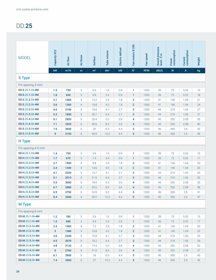
DD.25
Code Motor Diam. Ø [mm] Supply line Fan Speed [RPM] Power [W] Current [A] dB(A) 5 meter
- 4M 4 poles 250 230/1/50 1300 73 0.52 39
MODELFan motors
N°
Dimensions ConnectionsØ
drainA B C D E IN OUT
mm
DD.x.25.1.xx 1 750 610 192 630 430 12 12 1”
DD.x.25.2.xx 2 1150 610 192 630 830 12 16 1”
DD.x.25.3.xx 3 1550 610 205 630 1230 12 16 1”
DD.x.25.4.xx 4 1950 610 205 630 1630 12 22 1”
DD.x.25.5.xx 5 2350 610 205 630 2030 16 22 1” ¼
29
Unit coolers and brine units
MODELCa
paci
ty S
C2
Air fl
ow
Air t
hrow
Surf
ace
Tube
vol
ume
Elec
tric
def
rost
Fan
mot
ors
Ø 2
50
Fan
spee
d
Soun
d pr
essu
re
leve
l - 5
m
Pow
er
cons
umpt
ion
Curr
ent
cons
umpt
ion
Wei
ght
kW m3/h m m2 dm3 kW N° RPM dB(A) W A kg
S Type
Fin spacing 3 mmDD.S.25.1.04-4M 1.5 730 3 6.6 1.6 0.9 1 1300 39 73 0.52 16
DD.S.25.1.06-4M 1.8 630 3 9.9 2.4 0.9 1 1300 39 73 0.52 18
DD.S.25.2.04-4M 3.1 1460 4 13.2 2.9 1.8 2 1300 41 146 1.04 21
DD.S.25.2.06-4M 3.6 1260 4 19.8 4.3 1.8 2 1300 41 146 1.04 24
DD.S.25.3.04-4M 4.6 2190 5 19.8 4.1 2.7 3 1300 44 219 1.56 27
DD.S.25.3.06-4M 5.3 1890 5 29.7 6.4 2.7 3 1300 44 219 1.56 31
DD.S.25.4.04-4M 6.1 2920 6 26.4 5.3 3.6 4 1300 45 292 2.08 35
DD.S.25.4.06-4M 7.1 2520 6 39.6 8.3 3.6 4 1300 45 292 2.08 40
DD.S.25.5.04-4M 7.5 3650 6 33 6.5 4.4 5 1300 46 365 2.6 43
DD.S.25.5.06-4M 9 3150 6 49.5 10.2 4.4 5 1300 46 365 2.6 49
H Type
Fin spacing 4.5 mmDD.H.25.1.04-4M 1.4 750 3 4.9 1.6 0.9 1 1300 39 73 0.52 15
DD.H.25.1.06-4M 1.7 670 3 7.3 2.4 0.9 1 1300 39 73 0.52 17
DD.H.25.2.04-4M 2.7 1500 4 9.8 2.9 1.8 2 1300 41 146 1.04 20
DD.H.25.2.06-4M 3.4 1340 4 14.6 4.3 1.8 2 1300 41 146 1.04 23
DD.H.25.3.04-4M 4.1 2250 5 14.7 4.1 2.7 3 1300 44 219 1.56 26
DD.H.25.3.06-4M 5.1 2010 5 21.9 6.4 2.7 3 1300 44 219 1.56 30
DD.H.25.4.04-4M 5.5 3000 6 19.6 5.3 3.6 4 1300 45 292 2.08 33
DD.H.25.4.06-4M 6.7 2680 6 29.2 8.3 3.6 4 1300 45 292 2.08 38
DD.H.25.5.04-4M 6.9 3750 6 24.5 6.5 4.4 5 1300 46 365 2.6 41
DD.H.25.5.06-4M 8.4 3350 6 36.5 10.2 4.4 5 1300 46 365 2.6 47
M Type
Fin spacing 6 mmDD.M.25.1.04-4M 1.2 780 3 3.6 1.6 0.9 1 1300 39 73 0.52 15
DD.M.25.1.06-4M 1.5 690 3 5.4 2.4 0.9 1 1300 39 73 0.52 17
DD.M.25.2.04-4M 2.4 1560 4 7.2 2.9 1.8 2 1300 41 146 1.04 20
DD.M.25.2.06-4M 3 1380 4 10.8 4.3 1.8 2 1300 41 146 1.04 23
DD.M.25.3.04-4M 3.6 2340 5 10.8 4.1 2.7 3 1300 44 219 1.56 25
DD.M.25.3.06-4M 4.5 2070 5 16.2 6.4 2.7 3 1300 44 219 1.56 29
DD.M.25.4.04-4M 4.8 3120 6 14.4 5.3 3.6 4 1300 45 292 2.08 32
DD.M.25.4.06-4M 6 2760 6 21.6 8.3 3.6 4 1300 45 292 2.08 37
DD.M.25.5.04-4M 6.1 3900 6 18 6.5 4.4 5 1300 46 365 2.6 40
DD.M.25.5.06-4M 7.4 3450 6 27 10.2 4.4 5 1300 46 365 2.6 45
DD.25

B
D
70 A
E
260C
35
70 A
E
260C
35
70 A
E
260C
35
70 A
E26
0C35
E
70 A
E26
0C35
E
Roen Est Heat exchangers and more
30
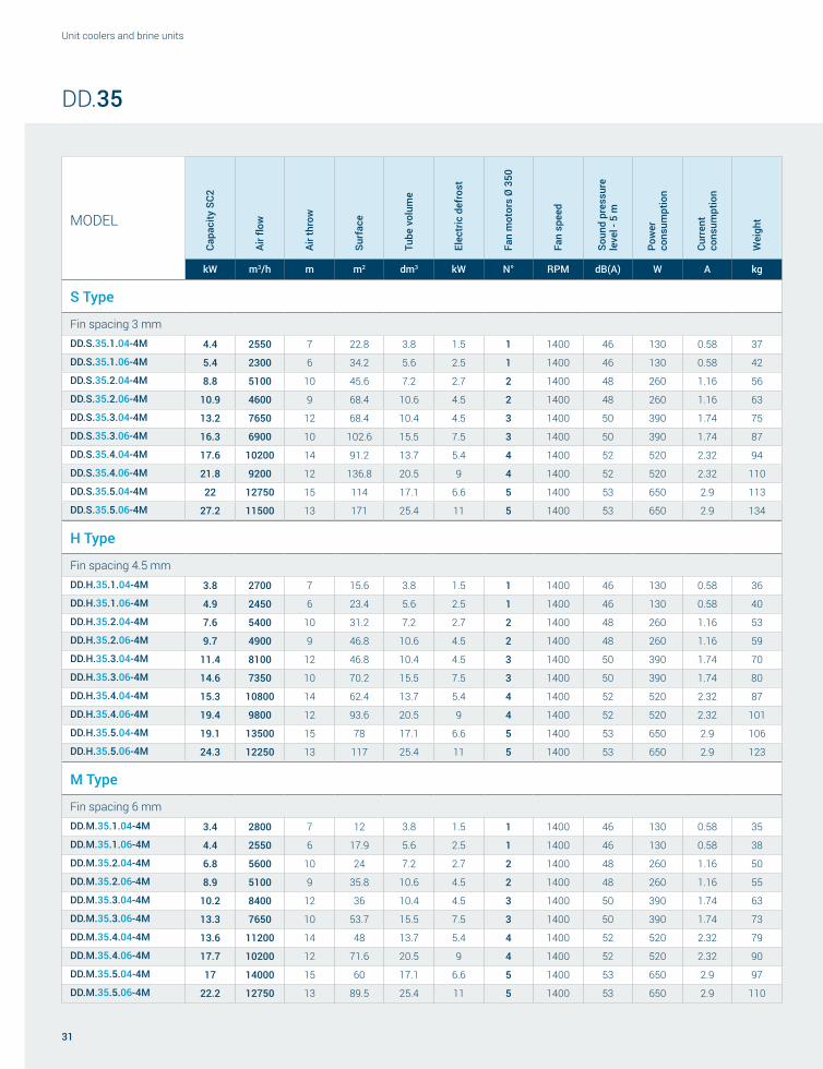
DD.35
Code Motor Diam. Ø [mm] Supply line Fan Speed [RPM] Power [W] Current [A] dB(A) 5 meter
- 4M 4 poles 350 230/1/50 1400 130 0.58 50
- 6M 6 poles 350 230/1/50 945 65 0.31 40
MODELFan motors
N°
Dimensions ConnectionsØ
drainA B C D E IN OUT
mm
DD.x.35.1.xx 1 1020 995 275 1010 630 12 22 1”
DD.x.35.2.xx 2 1620 995 275 1010 1230 12 22 1”
DD.x.35.3.xx 3 2220 995 290 1010 1830 12 22 1”
DD.x.35.4.xx 4 2820 995 290 1010 1215 16 28 1”
DD.x.35.5.xx 5 3420 995 290 1010 1515 22 28 1” ¼
31
Unit coolers and brine units
MODELCa
paci
ty S
C2
Air fl
ow
Air t
hrow
Surf
ace
Tube
vol
ume
Elec
tric
def
rost
Fan
mot
ors
Ø 3
50
Fan
spee
d
Soun
d pr
essu
re
leve
l - 5
m
Pow
er
cons
umpt
ion
Curr
ent
cons
umpt
ion
Wei
ght
kW m3/h m m2 dm3 kW N° RPM dB(A) W A kg
S Type
Fin spacing 3 mmDD.S.35.1.04-4M 4.4 2550 7 22.8 3.8 1.5 1 1400 46 130 0.58 37
DD.S.35.1.06-4M 5.4 2300 6 34.2 5.6 2.5 1 1400 46 130 0.58 42
DD.S.35.2.04-4M 8.8 5100 10 45.6 7.2 2.7 2 1400 48 260 1.16 56
DD.S.35.2.06-4M 10.9 4600 9 68.4 10.6 4.5 2 1400 48 260 1.16 63
DD.S.35.3.04-4M 13.2 7650 12 68.4 10.4 4.5 3 1400 50 390 1.74 75
DD.S.35.3.06-4M 16.3 6900 10 102.6 15.5 7.5 3 1400 50 390 1.74 87
DD.S.35.4.04-4M 17.6 10200 14 91.2 13.7 5.4 4 1400 52 520 2.32 94
DD.S.35.4.06-4M 21.8 9200 12 136.8 20.5 9 4 1400 52 520 2.32 110
DD.S.35.5.04-4M 22 12750 15 114 17.1 6.6 5 1400 53 650 2.9 113
DD.S.35.5.06-4M 27.2 11500 13 171 25.4 11 5 1400 53 650 2.9 134
H Type
Fin spacing 4.5 mmDD.H.35.1.04-4M 3.8 2700 7 15.6 3.8 1.5 1 1400 46 130 0.58 36
DD.H.35.1.06-4M 4.9 2450 6 23.4 5.6 2.5 1 1400 46 130 0.58 40
DD.H.35.2.04-4M 7.6 5400 10 31.2 7.2 2.7 2 1400 48 260 1.16 53
DD.H.35.2.06-4M 9.7 4900 9 46.8 10.6 4.5 2 1400 48 260 1.16 59
DD.H.35.3.04-4M 11.4 8100 12 46.8 10.4 4.5 3 1400 50 390 1.74 70
DD.H.35.3.06-4M 14.6 7350 10 70.2 15.5 7.5 3 1400 50 390 1.74 80
DD.H.35.4.04-4M 15.3 10800 14 62.4 13.7 5.4 4 1400 52 520 2.32 87
DD.H.35.4.06-4M 19.4 9800 12 93.6 20.5 9 4 1400 52 520 2.32 101
DD.H.35.5.04-4M 19.1 13500 15 78 17.1 6.6 5 1400 53 650 2.9 106
DD.H.35.5.06-4M 24.3 12250 13 117 25.4 11 5 1400 53 650 2.9 123
M Type
Fin spacing 6 mmDD.M.35.1.04-4M 3.4 2800 7 12 3.8 1.5 1 1400 46 130 0.58 35
DD.M.35.1.06-4M 4.4 2550 6 17.9 5.6 2.5 1 1400 46 130 0.58 38
DD.M.35.2.04-4M 6.8 5600 10 24 7.2 2.7 2 1400 48 260 1.16 50
DD.M.35.2.06-4M 8.9 5100 9 35.8 10.6 4.5 2 1400 48 260 1.16 55
DD.M.35.3.04-4M 10.2 8400 12 36 10.4 4.5 3 1400 50 390 1.74 63
DD.M.35.3.06-4M 13.3 7650 10 53.7 15.5 7.5 3 1400 50 390 1.74 73
DD.M.35.4.04-4M 13.6 11200 14 48 13.7 5.4 4 1400 52 520 2.32 79
DD.M.35.4.06-4M 17.7 10200 12 71.6 20.5 9 4 1400 52 520 2.32 90
DD.M.35.5.04-4M 17 14000 15 60 17.1 6.6 5 1400 53 650 2.9 97
DD.M.35.5.06-4M 22.2 12750 13 89.5 25.4 11 5 1400 53 650 2.9 110
DD.35

Roen Est Heat exchangers and more
32
MODEL
Capa
city
SC2
Air fl
ow
Air t
hrow
Surf
ace
Tube
vol
ume
Elec
tric
def
rost
Fan
mot
ors
Ø 3
50
Fan
spee
d
Soun
d pr
essu
re
leve
l - 5
m
Pow
er
cons
umpt
ion
Curr
ent
cons
umpt
ion
Wei
ght
kW m3/h m m2 dm3 kW N° RPM dB(A) W A kg
S Type
Fin spacing 3 mm
DD.S.35.1.04-6M 3.5 1700 5 22.8 3.8 1.5 1 945 40 65 0.41 37
DD.S.35.1.06-6M 4.3 1550 4 34.2 5.6 2.5 1 945 40 65 0.41 42
DD.S.35.2.04-6M 7.1 3400 7 45.6 7.2 2.7 2 945 42 130 0.82 56
DD.S.35.2.06-6M 8.5 3100 6 68.4 10.6 4.5 2 945 42 130 0.82 63
DD.S.35.3.04-6M 10.6 5100 9 68.4 10.4 4.5 3 945 44 195 1.23 75
DD.S.35.3.06-6M 12.8 4650 7 102.6 15.5 7.5 3 945 44 195 1.23 87
DD.S.35.4.04-6M 14.2 6800 10 91.2 13.7 5.4 4 945 46 260 1.64 94
DD.S.35.4.06-6M 17 6200 8 136.8 20.5 9 4 945 46 260 1.64 110
DD.S.35.5.04-6M 17.7 8500 11 114 17.1 6.6 5 945 47 325 2.05 113
DD.S.35.5.06-6M 21.3 7750 9 171 25.4 11 5 945 47 325 2.05 134
H Type
Fin spacing 4.5 mm
DD.H.35.1.04-6M 3.1 1800 5 15.6 3.8 1.5 1 945 40 65 0.41 36
DD.H.35.1.06-6M 3.9 1650 4 23.4 5.6 2.5 1 945 40 65 0.41 40
DD.H.35.2.04-6M 6.2 3600 7 31.2 7.2 2.7 2 945 42 130 0.82 53
DD.H.35.2.06-6M 7.8 3300 6 46.8 10.6 4.5 2 945 42 130 0.82 59
DD.H.35.3.04-6M 9.2 5400 9 46.8 10.4 4.5 3 945 44 195 1.23 70
DD.H.35.3.06-6M 11.7 4950 7 70.2 15.5 7.5 3 945 44 195 1.23 80
DD.H.35.4.04-6M 12.3 7200 10 62.4 13.7 5.4 4 945 46 260 1.64 87
DD.H.35.4.06-6M 15.5 6600 8 93.6 20.5 9 4 945 46 260 1.64 101
DD.H.35.5.04-6M 15.4 9000 11 78 17.1 6.6 5 945 47 325 2.05 106
DD.H.35.5.06-6M 19.4 8250 9 117 25.4 11 5 945 47 325 2.05 123
M Type
Fin spacing 6 mm
DD.M.35.1.04-6M 2.8 1850 5 12 3.8 1.5 1 945 40 65 0.41 35
DD.M.35.1.06-6M 3.5 1700 4 17.9 5.6 2.5 1 945 40 65 0.41 38
DD.M.35.2.04-6M 5.5 3700 7 24 7.2 2.7 2 945 42 130 0.82 50
DD.M.35.2.06-6M 7.1 3400 6 35.8 10.6 4.5 2 945 42 130 0.82 55
DD.M.35.3.04-6M 8.3 5550 9 36 10.4 4.5 3 945 44 195 1.23 63
DD.M.35.3.06-6M 10.6 5100 7 53.7 15.5 7.5 3 945 44 195 1.23 73
DD.M.35.4.04-6M 11 7400 10 48 13.7 5.4 4 945 46 260 1.64 79
DD.M.35.4.06-6M 14.2 6800 8 71.6 20.5 9 4 945 46 260 1.64 90
DD.M.35.5.04-6M 13.8 9250 11 60 17.1 6.6 5 945 47 325 2.05 97
DD.M.35.5.06-6M 17.7 8500 9 89.5 25.4 11 5 945 47 325 2.05 110
DD.35

A
E1
500C
70 A
E1
500C
70 A
E150
0C50
70 A
E1
500C
50
E2
70 A
E1
500C
50
E2
705050
B
D
33
Unit coolers and brine units
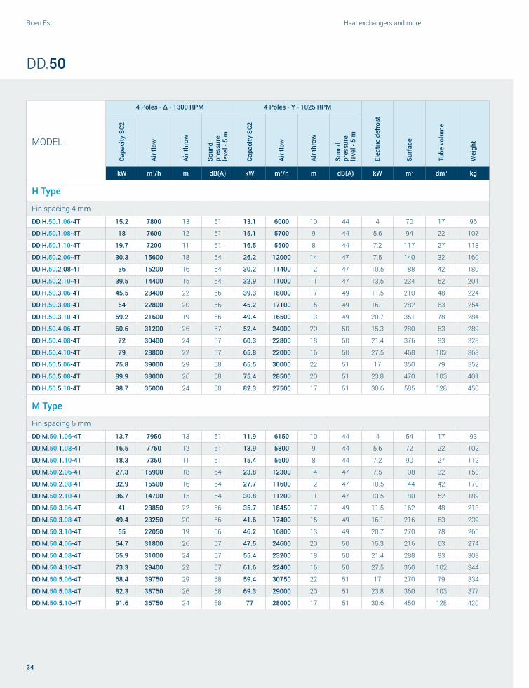
DD.50
Code Motor Diam. Ø [mm] Supply lineΔ Y
Speed [RPM] Power [W] Current [A] dB(A) 5 m Speed [RPM] Power [W] Current [A] dB(A) 5 m
- 4T 4 poles 500 400/3/50 1300 770 1.70 51 1025 490 0.84 44
- 6T 6 poles 500 400/3/50 870 280 0.62 42 610 140 0.31 37
MODELFan motors
N°
Dimensions ConnectionsØ
drainA B C D E1 E2 IN OUT
mm
DD.x.50.1.xx 1 1310 1560 500 1660 870 / 16 28 2x1”
DD.x.50.2.xx 2 2210 1560 500 1660 1770 / 22 35 2x1”
DD.x.50.3.xx 3 3110 1560 500 1660 2670 / 28 42 2x1”-¼
DD.x.50.4.xx 4 4010 1560 500 1660 1800 1770 35 54 2x1”-½
DD.x.50.5.xx 5 4910 1560 500 1660 1800 2670 35 54 2x1”-½
Roen Est Heat exchangers and more
34
MODEL
4 Poles - Δ - 1300 RPM 4 Poles - Y - 1025 RPM
Elec
tric
def
rost
Surf
ace
Tube
vol
ume
Wei
ght
Capa
city
SC2
Air fl
ow
Air t
hrow
Soun
d pr
essu
re
leve
l - 5
m
Capa
city
SC2
Air fl
ow
Air t
hrow
Soun
d pr
essu
re
leve
l - 5
m
kW m3/h m dB(A) kW m3/h m dB(A) kW m2 dm3 kg
H Type
Fin spacing 4 mm
DD.H.50.1.06-4T 15.2 7800 13 51 13.1 6000 10 44 4 70 17 96
DD.H.50.1.08-4T 18 7600 12 51 15.1 5700 9 44 5.6 94 22 107
DD.H.50.1.10-4T 19.7 7200 11 51 16.5 5500 8 44 7.2 117 27 118
DD.H.50.2.06-4T 30.3 15600 18 54 26.2 12000 14 47 7.5 140 32 160
DD.H.50.2.08-4T 36 15200 16 54 30.2 11400 12 47 10.5 188 42 180
DD.H.50.2.10-4T 39.5 14400 15 54 32.9 11000 11 47 13.5 234 52 201
DD.H.50.3.06-4T 45.5 23400 22 56 39.3 18000 17 49 11.5 210 48 224
DD.H.50.3.08-4T 54 22800 20 56 45.2 17100 15 49 16.1 282 63 254
DD.H.50.3.10-4T 59.2 21600 19 56 49.4 16500 13 49 20.7 351 78 284
DD.H.50.4.06-4T 60.6 31200 26 57 52.4 24000 20 50 15.3 280 63 289
DD.H.50.4.08-4T 72 30400 24 57 60.3 22800 18 50 21.4 376 83 328
DD.H.50.4.10-4T 79 28800 22 57 65.8 22000 16 50 27.5 468 102 368
DD.H.50.5.06-4T 75.8 39000 29 58 65.5 30000 22 51 17 350 79 352
DD.H.50.5.08-4T 89.9 38000 26 58 75.4 28500 20 51 23.8 470 103 401
DD.H.50.5.10-4T 98.7 36000 24 58 82.3 27500 17 51 30.6 585 128 450
M Type
Fin spacing 6 mm
DD.M.50.1.06-4T 13.7 7950 13 51 11.9 6150 10 44 4 54 17 93
DD.M.50.1.08-4T 16.5 7750 12 51 13.9 5800 9 44 5.6 72 22 102
DD.M.50.1.10-4T 18.3 7350 11 51 15.4 5600 8 44 7.2 90 27 112
DD.M.50.2.06-4T 27.3 15900 18 54 23.8 12300 14 47 7.5 108 32 153
DD.M.50.2.08-4T 32.9 15500 16 54 27.7 11600 12 47 10.5 144 42 170
DD.M.50.2.10-4T 36.7 14700 15 54 30.8 11200 11 47 13.5 180 52 189
DD.M.50.3.06-4T 41 23850 22 56 35.7 18450 17 49 11.5 162 48 213
DD.M.50.3.08-4T 49.4 23250 20 56 41.6 17400 15 49 16.1 216 63 239
DD.M.50.3.10-4T 55 22050 19 56 46.2 16800 13 49 20.7 270 78 266
DD.M.50.4.06-4T 54.7 31800 26 57 47.5 24600 20 50 15.3 216 63 274
DD.M.50.4.08-4T 65.9 31000 24 57 55.4 23200 18 50 21.4 288 83 308
DD.M.50.4.10-4T 73.3 29400 22 57 61.6 22400 16 50 27.5 360 102 344
DD.M.50.5.06-4T 68.4 39750 29 58 59.4 30750 22 51 17 270 79 334
DD.M.50.5.08-4T 82.3 38750 26 58 69.3 29000 20 51 23.8 360 103 377
DD.M.50.5.10-4T 91.6 36750 24 58 77 28000 17 51 30.6 450 128 420
DD.50
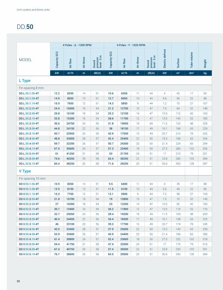
35
Unit coolers and brine units
MODEL
4 Poles - Δ - 1300 RPM 4 Poles - Y - 1025 RPM
Elec
tric
def
rost
Surf
ace
Tube
vol
ume
Wei
ght
Capa
city
SC2
Air fl
ow
Air t
hrow
Soun
d pr
essu
re
leve
l - 5
m
Capa
city
SC2
Air fl
ow
Air t
hrow
Soun
d pr
essu
re
leve
l - 5
m
kW m3/h m dB(A) kW m3/h m dB(A) kW m2 dm3 kg
L Type
Fin spacing 8 mm
DD.L.50.1.06-4T 12.2 8250 14 51 10.6 6350 11 44 4 42 17 90
DD.L.50.1.08-4T 14.9 8050 13 51 12.7 6050 10 44 5.6 56 22 98
DD.L.50.1.10-4T 16.9 7650 12 51 14.3 5850 9 44 7.2 70 27 107
DD.L.50.2.06-4T 24.4 16500 19 54 21.2 12700 15 47 7.5 84 32 148
DD.L.50.2.08-4T 29.8 16100 18 54 25.3 12100 14 47 10.5 112 42 163
DD.L.50.2.10-4T 33.8 15300 16 54 28.6 11700 12 47 13.5 140 52 180
DD.L.50.3.06-4T 36.6 24750 24 56 31.8 19050 19 49 11.5 126 48 205
DD.L.50.3.08-4T 44.8 24150 22 56 38 18150 17 49 16.1 168 63 229
DD.L.50.3.10-4T 50.7 22950 20 56 42.9 17550 15 49 20.7 210 78 252
DD.L.50.4.06-4T 48.8 33000 28 57 42.4 25400 22 50 15.3 168 63 264
DD.L.50.4.08-4T 59.7 32200 26 57 50.7 24200 20 50 21.4 224 83 294
DD.L.50.4.10-4T 67.5 30600 24 57 57.3 23400 18 50 27.5 280 102 326
DD.L.50.5.06-4T 61 41250 31 58 53 31750 24 51 17 210 79 321
DD.L.50.5.08-4T 74.6 40250 29 58 63.4 30250 22 51 23.8 280 103 369
DD.L.50.5.10-4T 84.4 38250 26 58 71.6 29250 20 51 30.6 350 128 397
V Type
Fin spacing 10 mm
DD.V.50.1.06-4T 10.9 8350 14 51 9.5 6400 11 44 4 35 17 89
DD.V.50.1.08-4T 13.5 8150 13 51 11.5 6100 10 44 5.6 46 22 96
DD.V.50.1.10-4T 15.3 7700 12 51 13.1 5900 9 44 7.2 58 27 105
DD.V.50.2.06-4T 21.8 16700 19 54 19 12800 15 47 7.5 70 32 145
DD.V.50.2.08-4T 27 16300 18 54 23 12200 14 47 10.5 92 42 160
DD.V.50.2.10-4T 30.7 15400 16 54 26.2 11800 12 47 13.5 116 52 176
DD.V.50.3.06-4T 32.7 25050 24 56 28.4 19200 19 49 11.5 105 48 200
DD.V.50.3.08-4T 40.4 24450 22 56 34.4 18300 17 49 16.1 138 63 225
DD.V.50.3.10-4T 46 23100 20 56 39.3 17700 15 49 20.7 174 78 245
DD.V.50.4.06-4T 43.5 33400 28 57 37.9 25600 22 50 15.3 140 63 259
DD.V.50.4.08-4T 53.9 32600 26 57 45.9 24400 20 50 21.4 184 83 286
DD.V.50.4.10-4T 61.4 30800 24 57 52.4 23600 18 50 27.5 232 102 318
DD.V.50.5.06-4T 54.4 41750 31 58 47.4 32000 24 51 17 175 79 315
DD.V.50.5.08-4T 67.4 40750 29 58 57.4 30500 22 51 23.8 230 103 351
DD.V.50.5.10-4T 76.7 38500 26 58 65.5 29500 20 51 30.6 290 128 384
DD.50

Roen Est Heat exchangers and more
36
MODEL
4 Poles - Δ - 1300 RPM 4 Poles - Y - 1025 RPM
Elec
tric
def
rost
Surf
ace
Tube
vol
ume
Wei
ght
Capa
city
SC2
Air fl
ow
Air t
hrow
Soun
d pr
essu
re
leve
l - 5
m
Capa
city
SC2
Air fl
ow
Air t
hrow
Soun
d pr
essu
re
leve
l - 5
m
kW m3/h m dB(A) kW m3/h m dB(A) kW m2 dm3 kg
I Type
Fin spacing 12 mm
DD.I.50.1.06-4T 10.2 8400 14 51 8.9 6450 11 44 4 30 17 88
DD.I.50.1.08-4T 12.7 8200 13 51 10.8 6150 10 44 5.6 40 22 95
DD.I.50.1.10-4T 14.5 7750 12 51 12.4 5900 9 44 7.2 50 27 104
DD.I.50.2.06-4T 20.4 16800 19 54 17.7 12900 15 47 7.5 60 32 144
DD.I.50.2.08-4T 25.4 16400 18 54 21.7 12300 14 47 10.5 80 42 158
DD.I.50.2.10-4T 29.1 15500 16 54 24.7 11800 12 47 13.5 100 52 173
DD.I.50.3.06-4T 30.6 25200 24 56 26.6 19350 19 49 11.5 90 48 196
DD.I.50.3.08-4T 38.1 24600 22 56 32.5 18450 17 49 16.1 120 63 220
DD.I.50.3.10-4T 43.6 23250 20 56 37.1 17700 15 49 20.7 150 78 240
DD.I.50.4.06-4T 40.8 33600 28 57 35.5 25800 22 50 15.3 120 63 255
DD.I.50.4.08-4T 50.8 32800 26 57 43.3 24600 20 50 21.4 160 83 281
DD.I.50.4.10-4T 58.1 31000 24 57 49.4 23600 18 50 27.5 200 102 312
DD.I.50.5.06-4T 51 42000 31 58 44.4 32250 24 51 17 150 79 311
DD.I.50.5.08-4T 63.5 41000 29 58 54.1 30750 22 51 23.8 200 103 342
DD.I.50.5.10-4T 72.7 38750 26 58 61.8 29700 20 51 30.6 250 128 372
DD.50

37
Unit coolers and brine units
MODEL
6 Poles - Δ - 870 RPM 6 Poles - Y - 610 RPM
Elec
tric
def
rost
Surf
ace
Tube
vol
ume
Wei
ght
Capa
city
SC2
Air fl
ow
Air t
hrow
Soun
d pr
essu
re
leve
l - 5
m
Capa
city
SC2
Air fl
ow
Air t
hrow
Soun
d pr
essu
re
leve
l - 5
m
kW m3/h m dB(A) kW m3/h m dB(A) kW m2 dm3 kg
H Type
Fin spacing 4 mm
DD.H.50.1.06-6T 12.1 5300 9 42 9.9 3800 6 37 4 70 17 96
DD.H.50.1.08-6T 14 5100 8 42 11.1 3600 6 37 5.6 94 22 107
DD.H.50.1.10-6T 15 4800 8 42 11.6 3400 6 37 7.2 117 27 118
DD.H.50.2.06-6T 24.2 10600 12 45 19.7 7600 8 40 7.5 140 32 160
DD.H.50.2.08-6T 28.1 10200 11 45 22.1 7200 8 40 10.5 188 42 180
DD.H.50.2.10-6T 30 9600 11 45 23.2 6800 8 40 13.5 234 52 201
DD.H.50.3.06-6T 36.3 15900 15 47 29.6 11400 10 42 11.5 210 48 224
DD.H.50.3.08-6T 42.1 15300 13 47 33.2 10800 10 42 16.1 282 63 254
DD.H.50.3.10-6T 44.9 14400 13 47 34.8 10200 10 42 20.7 351 78 284
DD.H.50.4.06-6T 48.4 21200 18 48 39.5 15200 12 43 15.3 280 63 289
DD.H.50.4.08-6T 56.1 20400 16 48 44.2 14400 12 43 21.4 376 83 328
DD.H.50.4.10-6T 59.9 19200 16 48 46.5 13600 12 43 27.5 468 102 368
DD.H.50.5.06-6T 60.5 26500 20 50 49.4 19000 13 44 17 350 79 352
DD.H.50.5.08-6T 70.2 25500 17 50 55.3 18000 13 44 23.8 470 103 401
DD.H.50.5.10-6T 74.9 24000 17 50 58.1 17000 13 44 30.6 585 128 450
M Type
Fin spacing 6 mm
DD.M.50.1.06-6T 11 5400 9 42 9 3850 6 37 4 54 17 93
DD.M.50.1.08-6T 12.9 5200 8 42 10.3 3650 6 37 5.6 72 22 102
DD.M.50.1.10-6T 14.1 4900 8 42 11 3450 6 37 7.2 90 27 112
DD.M.50.2.06-6T 22 10800 12 45 18 7700 8 40 7.5 108 32 153
DD.M.50.2.08-6T 25.9 10400 11 45 20.6 7300 8 40 10.5 144 42 170
DD.M.50.2.10-6T 28.1 9800 11 45 22 6900 8 40 13.5 180 52 189
DD.M.50.3.06-6T 33.1 16200 15 47 27.1 11550 10 42 11.5 162 48 213
DD.M.50.3.08-6T 38.8 15600 13 47 30.8 10950 10 42 16.1 216 63 239
DD.M.50.3.10-6T 42.2 14700 13 47 33 10350 10 42 20.7 270 78 266
DD.M.50.4.06-6T 44.1 21600 18 48 36.1 15400 12 43 15.3 216 63 274
DD.M.50.4.08-6T 51.8 20800 16 48 41.1 14600 12 43 21.4 288 83 308
DD.M.50.4.10-6T 56.3 19600 16 48 44 13800 12 43 27.5 360 102 344
DD.M.50.5.06-6T 55.1 27000 20 50 45.1 19250 13 44 17 270 79 334
DD.M.50.5.08-6T 64.7 26000 17 50 51.4 18250 13 44 23.8 360 103 377
DD.M.50.5.10-6T 70.3 24500 17 50 54.9 17250 13 44 30.6 450 128 420
DD.50

Roen Est Heat exchangers and more
38
DD.50
MODEL
6 Poles - Δ - 870 RPM 6 Poles - Y - 610 RPM
Elec
tric
def
rost
Surf
ace
Tube
vol
ume
Wei
ght
Capa
city
SC2
Air fl
ow
Air t
hrow
Soun
d pr
essu
re
leve
l - 5
m
Capa
city
SC2
Air fl
ow
Air t
hrow
Soun
d pr
essu
re
leve
l - 5
m
kW m3/h m dB(A) kW m3/h m dB(A) kW m2 dm3 kg
L Type
Fin spacing 8 mm
DD.L.50.1.06-6T 9.9 5600 10 42 8.2 4050 7 37 4 42 17 90
DD.L.50.1.08-6T 11.8 5400 9 42 9.5 3800 7 37 5.6 56 22 98
DD.L.50.1.10-6T 13.1 5100 9 42 10.4 3600 7 37 7.2 70 27 107
DD.L.50.2.06-6T 19.8 11200 14 45 16.5 8100 9 40 7.5 84 32 148
DD.L.50.2.08-6T 23.7 10800 12 45 19 7600 9 40 10.5 112 42 163
DD.L.50.2.10-6T 26.2 10200 12 45 20.8 7200 9 40 13.5 140 52 180
DD.L.50.3.06-6T 29.7 16800 17 47 24.7 12150 12 42 11.5 126 48 205
DD.L.50.3.08-6T 35.5 16200 15 47 28.6 11400 12 42 16.1 168 63 229
DD.L.50.3.10-6T 39.3 15300 15 47 31.2 10800 12 42 20.7 210 78 252
DD.L.50.4.06-6T 39.6 22400 20 48 32.9 16200 14 43 15.3 168 63 264
DD.L.50.4.08-6T 47.4 21600 18 48 38.1 15200 14 43 21.4 224 83 294
DD.L.50.4.10-6T 52.5 20400 18 48 41.6 14400 14 43 27.5 280 102 326
DD.L.50.5.06-6T 49.5 28000 22 50 41.2 20250 15 44 17 210 79 321
DD.L.50.5.08-6T 59.2 27000 20 50 47.6 19000 15 44 23.8 280 103 369
DD.L.50.5.10-6T 65.6 25500 20 50 52 18000 15 44 30.6 350 128 397
V Type
Fin spacing 10 mm
DD.V.50.1.06-6T 8.9 5700 10 42 7.4 4100 7 37 4 35 17 89
DD.V.50.1.08-6T 10.7 5450 9 42 8.7 3850 7 37 5.6 46 22 96
DD.V.50.1.10-6T 12 5150 9 42 9.7 3650 7 37 7.2 58 27 105
DD.V.50.2.06-6T 17.8 11400 14 45 14.8 8200 9 40 7.5 70 32 145
DD.V.50.2.08-6T 21.5 10900 12 45 17.4 7700 9 40 10.5 92 42 160
DD.V.50.2.10-6T 24.1 10300 12 45 19.3 7300 9 40 13.5 116 52 176
DD.V.50.3.06-6T 26.7 17100 17 47 22.3 12300 12 42 11.5 105 48 200
DD.V.50.3.08-6T 32.2 16350 15 47 26.2 11550 12 42 16.1 138 63 225
DD.V.50.3.10-6T 36.1 15450 15 47 29 10950 12 42 20.7 174 78 245
DD.V.50.4.06-6T 35.6 22800 20 48 29.7 16400 14 43 15.3 140 63 259
DD.V.50.4.08-6T 43 21800 18 48 34.9 15400 14 43 21.4 184 83 286
DD.V.50.4.10-6T 48.2 20600 18 48 38.6 14600 14 43 27.5 232 102 318
DD.V.50.5.06-6T 44.5 28500 22 50 37.1 20500 15 44 17 175 79 315
DD.V.50.5.08-6T 53.7 27250 20 50 43.6 19250 15 44 23.8 230 103 351
DD.V.50.5.10-6T 60.2 25750 20 50 48.3 18250 15 44 30.6 290 128 384

39
Unit coolers and brine units
DD.50
MODEL
6 Poles - Δ - 870 RPM 6 Poles - Y - 610 RPM
Elec
tric
def
rost
Surf
ace
Tube
vol
ume
Wei
ght
Capa
city
SC2
Air fl
ow
Air t
hrow
Soun
d pr
essu
re
leve
l - 5
m
Capa
city
SC2
Air fl
ow
Air t
hrow
Soun
d pr
essu
re
leve
l - 5
m
kW m3/h m dB(A) kW m3/h m dB(A) kW m2 dm3 kg
I Type
Fin spacing 12 mm
DD.I.50.1.06-6T 8.3 5750 10 42 7 4150 7 37 4 30 17 88
DD.I.50.1.08-6T 10.1 5500 9 42 8.3 3900 7 37 5.6 40 22 95
DD.I.50.1.10-6T 11.4 5200 9 42 9.2 3700 7 37 7.2 50 27 104
DD.I.50.2.06-6T 16.7 11500 14 45 13.9 8300 9 40 7.5 60 32 144
DD.I.50.2.08-6T 20.3 11000 12 45 16.5 7800 9 40 10.5 80 42 158
DD.I.50.2.10-6T 22.9 10400 12 45 18.4 7400 9 40 13.5 100 52 173
DD.I.50.3.06-6T 25 17250 17 47 20.9 12450 12 42 11.5 90 48 196
DD.I.50.3.08-6T 30.4 16500 15 47 24.8 11700 12 42 16.1 120 63 220
DD.I.50.3.10-6T 34.3 15600 15 47 27.7 11100 12 42 20.7 150 78 240
DD.I.50.4.06-6T 33.4 23000 20 48 27.8 16600 14 43 15.3 120 63 255
DD.I.50.4.08-6T 40.6 22000 18 48 33 15600 14 43 21.4 160 83 281
DD.I.50.4.10-6T 45.8 20800 18 48 36.9 14800 14 43 27.5 200 102 312
DD.I.50.5.06-6T 41.7 28750 22 50 34.8 20750 15 44 17 150 79 311
DD.I.50.5.08-6T 50.7 27500 20 50 41.3 19500 15 44 23.8 200 103 342
DD.I.50.5.10-6T 57.2 26000 20 50 46.1 18500 15 44 30.6 250 128 372

Roen Est Heat exchangers and more
40
CUBIC UNIT COOLERS250 / 300 / 350 / 450 / 500 / 630 CC, KC and IC Series
IT
ØØ Diametri motore disponibili: 250 mm, 300 mm, 350 mm, 450 mm, 500 mm e 630 mmØØ Numero motori disponibile:
¬ diametro motore 250 mm, 300 mm, 350 mm e 450 mm: da 1 a 5 motori ¬ diametro motore 500 mm: da 1 a 4 motori ¬ diametro motore 630 mm: da 2 a 4 motori
ØØ Passi alette disponibili: 4 mm, 6 mm, 8 mm, 10 mm e 12 mmØØ Tensione motori:
¬ 230 V / 1 / 50 Hz per diametro 300 mm, 350 mm ¬ 400 V / 3 / 50 Hz per diametro 450 mm, 500 mm e 630 mm
ØØ Grado di protezione motori: ¬ diametro 300 mm e 350 mm - IP44 ¬ diametro 450 mm, 500 mm, 630 mm - IP54
EN
ØØ Available fan motor diameters: 250 mm, 300 mm, 350 mm, 450 mm, 500 mm and 630 mmØØ Available number of fan motors:
¬ fan motor diameter 250 mm, 300 mm, 350 mm and 450 mm: from 1 to 5 motors ¬ fan motor diameter 500 mm: from 1 to 4 motors ¬ fan motor diameter 630 mm: from 2 to 4 motors
ØØ Available fin spacing: 4 mm, 6 mm, 8 mm, 10 mm and 12 mmØØ Fan motor voltage:
¬ 230 V / 1 / 50 Hz for diameter 300 mm, 350 mm ¬ 400 V / 3 / 50 Hz for diameter 450 mm, 500 mm and 630 mm
ØØ Fan motor protection class: ¬ Diameter 300 mm and 350 mm - IP44 ¬ Diameter 450 mm, 500 mm, 630 mm - IP54
DE
ØØ Verfügbare Motordurchmesser: 250 mm, 300 mm, 350 mm, 450 mm, 500 mm und 630 mmØØ Verfügbare Motorenanzahl:
¬ Motordurchmesser 250 mm, 300 mm, 350 mm und 450 mm: von 1 bis 5 Motoren ¬ Motordurchmesser 500 mm: von 1 bis 4 Motoren ¬ Motordurchmesser 630 mm: von 2 bis 4 Motoren
ØØ Abstand der Lamellenabstand: 4 mm, 6 mm, 8 mm, 10 mm und 12 mmØØ Motorspannung:
¬ 230 V / 1 / 50 Hz für Durchmesser 300 mm, 350 mm ¬ 400 V / 3 / 50 Hz für Durchmesser 450 mm, 500 mm und 630 mm
ØØ Schutzart der Motoren: ¬ Durchmesser 300 mm und 350 mm - IP44 ¬ Durchmesser 450 mm, 500 mm, 630 mm - IP54

41
Unit coolers and brine units
ES
ØØ Diámetros motores disponibles: 250 mm, 300 mm, 350 mm, 450 mm, 500 mm y 630 mmØØ Número motores disponible:
¬ diámetro motor 250 mm, 300 mm, 350 mm y 450 mm: de 1 a 5 motores ¬ diámetro motor 500 mm: de 1 a 4 motores ¬ diámetro motor 630 mm: de 2 a 4 motores
ØØ Pasos de aleta disponibles: 4 mm, 6 mm, 8 mm, 10 mm y 12 mmØØ Tensión Motores:
¬ 230 V / 1 / 50 Hz para diámetro 300 mm, 350 mm ¬ 400 V / 3 / 50 Hz para diámetro 450 mm, 500 mm y 630 mm
ØØ Grado de protección motores: ¬ diámetro 300 mm Y 350 mm - IP44 ¬ diámetro 450 mm, 500 mm, 630 mm - IP54
FR
ØØ Diamètres moteurs disponibles : 250 mm, 300 mm, 350 mm, 450 mm, 500 mm et 630 mmØØ Nombre de moteurs disponible :
¬ diamètre moteur 250 mm, 300 mm, 350 mm et 450 mm: de 1 à 5 moteurs ¬ diamètre moteur 500 mm: de 1 à 4 moteurs ¬ diamètre moteur 630 mm: de 2 à 4 moteurs
ØØ Pas ailettes disponibles : 4 mm, 6 mm, 8 mm, 10 mm et 12 mmØØ Tension moteurs :
¬ 230 V / 1 / 50 Hz pour diamètre 300 mm, 350 mm ¬ 400 V / 3 / 50 Hz pour diamètre 450 mm, 500 mm et 630 mm
ØØ Indice de protection moteurs : ¬ diamètre 300 mm et 350 mm - IP44 ¬ diamètre 450 mm, 500 mm, 630 mm - IP54
RU
ØØ Диаметр двигателей: 250 мм, 300 мм, 350 мм, 450 мм, 500 мм и 630 ммØØ Количество двигателей:
¬ диаметр двигателя 250 мм, 300 мм, 350 мм и 450 мм: от 1 до 5 двигателей ¬ диаметр двигателя 500 мм: от 1 до 4 двигателей ¬ диаметр двигателя 630 мм: от 2 до 4 двигателей
ØØ Шаг ребер: 4 мм, 6 мм, 8 мм, 10 мм и 12 ммØØ Напряжение двигателей:
¬ 230 В / 1 / 50 Гц для диаметра 300 мм, 350 мм ¬ 400 В / 3 / 50 Гц для диаметра 450 мм, 500 мм и 630 мм
ØØ Степень защиты двигателей: ¬ Диаметр 300 мм и 350 мм - IP44 ¬ Диаметр 450 мм, 500 мм, 630 мм – IP54
Aeroevaporatori cubiciKubische Luftverdampfer
Évaporateurs ventilés cubiquesAeroevaporadores cúbicos
Кубические воздухоохладители

E F
I
INOUT
A
B C D
H
Ă
C'
= =
Roen Est Heat exchangers and more
42
MODELFan motors
N°
Dimensions ConnectionsØ
drainA B C C’ D E F H I IN OUT
mm
CC.x.26.1.xx 1 700 130 425 / 130 400 324 363 356 12 12 1”
CC.x.26.2.xx 2 1100 130 825 / 130 400 324 363 356 12 12 1”
CC.x.26.3.xx 3 1500 130 1225 / 130 400 324 363 356 16 22 1”
CC.x.26.4.xx 4 1900 130 1625 / 130 400 324 363 356 16 28 1”¼
CC.x.26.5.xx 5 2700 130 2025 900 130 400 324 363 356 16 28 1”¼
Code Motor Diam. Ø [mm] Supply line Fan Speed [RPM] Power [W] Current [A] dB(A) 5 meter
CC.x.26.x.xx-4M 4 poles 254 230/1/50 1300 60 0.42 44
CC.26
TUBES
Ø7,94
OLD
NEW
Reduced tube diameter

43
Unit coolers and brine units
MODELCa
paci
ty S
C2
Capa
city
SC4
Air fl
ow
Air t
hrow
Surf
ace
Tube
vol
ume
Elec
tric
def
rost
Fan
mot
ors
Ø 2
54
Soun
d pr
essu
re
leve
l - 5
m
Pow
er
cons
umpt
ion
Curr
ent
cons
umpt
ion
Wei
ght
kW kW m3/h m m2 dm3 kW N° dB(A) W A kg
H Type
Fin spacing 4 mm
CC.H.26.1.04-4M 1,24 - 700 6 4,9 0,8 0,7 1 44 60 0,42 12
CC.H.26.1.06-4M 1,47 - 567 5 7,5 1,3 0,7 1 44 60 0,42 14
CC.H.26.2.04-4M 2,49 - 1401 6 9,9 1,6 1,4 2 47 120 0,84 21
CC.H.26.2.06-4M 2,94 - 1133 5 14,9 2,6 1,4 2 47 120 0,84 23
CC.H.26.3.04-4M 3,73 - 2101 6 14,8 2,4 2,2 3 49 180 1,26 29
CC.H.26.3.06-4M 4,41 - 1700 5 22,4 3,9 2,2 3 49 180 1,26 33
CC.H.26.4.04-4M 4,97 - 2802 6 19,7 3,2 2,9 4 50 240 1,68 40
CC.H.26.4.06-4M 5,88 - 2266 5 29,8 5,2 2,9 4 50 240 1,68 44
CC.H.26.5.04-4M 6,22 - 3502 6 24,7 4,0 3,6 5 51 300 2,1 51
CC.H.26.5.06-4M 7,35 - 2833 5 37,3 6,5 3,6 5 51 300 2,1 55
M Type
Fin spacing 6 mm
CC.M.26.1.04-4M 1,13 0,68 773 7 3,5 0,8 0,7 1 44 60 0,42 11
CC.M.26.1.06-4M 1,36 0,79 649 6 5,3 1,3 0,7 1 44 60 0,42 13
CC.M.26.2.04-4M 2,26 1,36 1545 7 6,9 1,6 1,4 2 47 120 0,84 19
CC.M.26.2.06-4M 2,71 1,58 1298 6 10,5 2,6 1,4 2 47 120 0,84 21
CC.M.26.3.04-4M 3,39 2,03 2318 7 10,4 2,4 2,2 3 49 180 1,26 26
CC.M.26.3.06-4M 4,07 2,37 1947 6 15,8 3,9 2,2 3 49 180 1,26 30
CC.M.26.4.04-4M 4,52 2,71 3090 7 13,9 3,2 2,9 4 50 240 1,68 36
CC.M.26.4.06-4M 5,42 3,16 2596 6 21,0 5,2 2,9 4 50 240 1,68 40
CC.M.26.5.04-4M 5,65 3,39 3863 7 17,3 4,0 3,6 5 51 300 2,1 46
CC.M.26.5.06-4M 6,78 3,96 3245 6 26,3 6,5 3,6 5 51 300 2,1 51
CC.26

E F
I
INOUT
120
60
40
55
A
B C D
H
Ă
C'
= =
Roen Est Heat exchangers and more
44
KC.31
Code Motor Diam. Ø [mm] Supply line Fan Speed [RPM] Power [W] Current [A] dB(A) 5 meter
KC.x.31.x.xx-4M 4 poles 300 230/1/50 1330 74 0.34 46
MODELFan motors
N°
Dimensions ConnectionsØ
drainA B C C’ D E F H I IN OUT
mm
KC.x.31.1.xx 1 750 130 470 / 130 400 380 410 415 12 16 1”
KC.x.31.2.xx 2 1200 130 920 / 130 400 380 410 415 12 16 1”
KC.x.31.3.xx 3 1650 130 1370 / 130 400 380 410 415 16 22 1”
KC.x.31.4.xx 4 2100 130 1820 / 130 400 380 410 415 16 22 1”
KC.x.31.5.xx 5 2550 130 2270 900 130 400 380 410 415 22 28 1”¼
OLD
NEW
Reduced tube diameter

45
Unit coolers and brine units
KC.31
MODELCa
paci
ty S
C2
Capa
city
SC4
Air fl
ow
Air t
hrow
Surf
ace
Tube
vol
ume
Elec
tric
def
rost
Fan
mot
ors
Ø 3
00
Soun
d pr
essu
re
leve
l - 5
m
Pow
er
cons
umpt
ion
Curr
ent
cons
umpt
ion
Wei
ght
kW kW m3/h m m2 dm3 kW N° dB(A) W A kg
H Type
Fin spacing 4 mm | Tubes Ø7,94 mm
KC.H.31.1.04-4M 2,1 - 1313 10 7,5 1,2 0,8 1 46 74 0,34 19
KC.H.31.1.06-4M 2,7 - 1208 9 11,2 1,8 1,1 1 46 74 0,34 22
KC.H.31.2.04-4M 4,2 - 2625 10 15,0 2,4 1,6 2 49 74 0,34 32
KC.H.31.2.06-4M 5,4 - 2415 9 22,4 3,6 1,0 2 49 148 0,68 36
KC.H.31.3.04-4M 6,4 - 3938 10 22,4 3,6 2,4 3 51 148 0,68 44
KC.H.31.3.06-4M 8,1 - 3623 9 33,7 5,4 3,2 3 51 148 0,68 51
KC.H.31.4.04-4M 8,5 - 5250 10 29,9 4,8 3,2 4 52 296 1,02 58
KC.H.31.4.06-4M 10,9 - 4830 9 44,9 7,2 4,3 4 52 296 1,02 66
KC.H.31.5.04-4M 10,6 - 6563 10 37,4 6,0 1,0 5 53 370 1,36 71
KC.H.31.5.06-4M 13,6 - 6038 9 56,1 9,0 5,4 5 53 370 1,36 81
M Type
Fin spacing 6 mm | Tubes Ø7,94 mm
KC.M.31.1.04-4M 1,9 1,2 1418 10 5,2 1,2 0,8 1 46 74 0,34 18
KC.M.31.1.06-4M 2,4 1,4 1260 9 7,8 1,8 1,1 1 46 74 0,34 21
KC.M.31.2.04-4M 3,8 2,4 2835 10 10,3 2,4 1,6 2 49 74 0,34 31
KC.M.31.2.06-4M 4,7 2,8 2520 9 15,6 3,6 1,0 2 49 148 0,68 35
KC.M.31.3.04-4M 5,7 3,5 4253 10 15,5 3,6 2,4 3 51 148 0,68 43
KC.M.31.3.06-4M 7,1 4,2 3780 9 23,4 5,4 3,2 3 51 148 0,68 50
KC.M.31.4.04-4M 7,6 4,7 5670 10 20,7 4,8 3,2 4 52 296 1,02 56
KC.M.31.4.06-4M 9,4 5,7 5040 9 31,2 7,2 4,3 4 52 296 1,02 64
KC.M.31.5.04-4M 9,4 5,9 7088 10 25,9 6,0 1,0 5 53 370 1,36 69
KC.M.31.5.06-4M 11,8 7,1 6300 9 39,1 9,0 5,4 5 53 370 1,36 79
L Type
Fin spacing 8 mm | Tubes Ø9,52 mm 35x35
KC.L.31.1.03-4M 1,24 0,79 1648 12 4,43 1,00 0,90 1 46 74 0,34 21
KC.L.31.1.05-4M 1,81 1,24 1442 11 7,42 1,60 1,20 1 46 74 0,34 24
KC.L.31.2.03-4M 2,49 1,58 3296 12 8,86 2,00 2,40 2 49 74 0,34 35
KC.L.31.2.05-4M 3,62 2,49 2884 11 14,83 3,20 3,20 2 49 148 0,68 39
KC.L.31.3.03-4M 3,73 2,37 4944 12 13,29 3,00 3,00 3 51 148 0,68 50
KC.L.31.3.05-4M 5,42 3,73 4326 11 22,25 4,80 4,00 3 51 148 0,68 57
KC.L.31.4.03-4M 4,97 3,16 6592 12 17,72 4,00 4,50 4 52 296 1,02 64
KC.L.31.4.05-4M 7,23 4,97 5768 11 29,66 6,40 6,00 4 52 296 1,02 72
KC.L.31.5.03-4M 6,22 3,96 8240 12 22,15 5,00 5,40 5 53 370 1,36 79
KC.L.31.5.05-4M 9,04 6,22 7210 11 37,08 8,00 7,20 5 53 370 1,36 89

Roen Est Heat exchangers and more
46
KC.31
MODEL
Capa
city
SC2
Capa
city
SC4
Air fl
ow
Air t
hrow
Surf
ace
Tube
vol
ume
Elec
tric
def
rost
Fan
mot
ors
Ø 3
00
Soun
d pr
essu
re
leve
l - 5
m
Pow
er
cons
umpt
ion
Curr
ent
cons
umpt
ion
Wei
ght
kW kW m3/h m m2 dm3 kW N° dB(A) W A kg
V Type
Fin spacing 10 mm | Tubes Ø12 mm
KC.V.31.1.03-4M 1,18 0,83 1700 13 3,61 1,55 0,90 1 46 74 0,34 21
KC.V.31.1.05-4M 1,77 1,18 1494 12 6,08 2,48 1,20 1 46 74 0,34 24
KC.V.31.2.03-4M 2,36 1,65 3399 13 7,21 3,10 2,40 2 49 74 0,34 35
KC.V.31.2.05-4M 3,54 2,36 2987 12 12,15 4,96 3,20 2 49 148 0,68 39
KC.V.31.3.03-4M 3,54 2,48 5099 13 10,82 4,65 3,00 3 51 148 0,68 50
KC.V.31.3.05-4M 5,31 3,54 4481 12 18,23 7,44 4,00 3 51 148 0,68 57
KC.V.31.4.03-4M 4,72 3,30 6798 13 14,42 6,20 4,50 4 52 296 1,02 64
KC.V.31.4.05-4M 7,08 4,72 5974 12 24,31 9,22 6,00 4 52 296 1,02 72
KC.V.31.5.03-4M 5,90 4,13 8498 13 18,03 7,75 5,40 5 53 370 1,36 79
KC.V.31.5.05-4M 8,85 5,90 7468 12 30,39 12,40 7,20 5 53 370 1,36 89
I Type
Fin spacing 12 mm | Tubes Ø12 mm
KC.I.31.1.03-4M 1,06 0,71 1751 13 3,09 1,55 0,90 1 46 74 0,34 19
KC.I.31.1.05-4M 1,65 1,06 1545 12 5,15 2,48 1,20 1 46 74 0,34 22
KC.I.31.2.03-4M 2,12 1,42 3502 13 6,18 3,10 2,40 2 49 74 0,34 32
KC.I.31.2.05-4M 3,30 2,12 3090 12 10,30 4,96 3,20 2 49 148 0,68 36
KC.I.31.3.03-4M 3,19 2,12 5253 13 9,27 4,65 3,00 3 51 148 0,68 44
KC.I.31.3.05-4M 4,96 3,19 4635 12 15,45 7,44 4,00 3 51 148 0,68 51
KC.I.31.4.03-4M 4,25 2,83 7004 13 12,36 6,20 4,50 4 52 296 1,02 58
KC.I.31.4.05-4M 6,61 4,25 6180 12 20,60 9,22 6,00 4 52 296 1,02 66
KC.I.31.5.03-4M 5,31 3,54 8755 13 15,45 7,75 5,40 5 53 370 1,36 71
KC.I.31.5.05-4M 8,26 5,31 7725 12 25,75 12,40 7,20 5 53 370 1,36 81

47
Unit coolers and brine units
E F
I
INOUT
120
60
40
55
A
B C D
H
Ă
C'
= =
Code Motor Diam. Ø [mm] Supply line Fan Speed [RPM] Power [W] Current [A] dB(A) 5 meter
KC.x.35.x.xx-4M 4 poles 350 230/1/50 1410 175 0.80 50
MODELFan motors
N°
Dimensions ConnectionsØ
drainA B C C’ D E F H I IN OUT
mm
KC.x.35.1.xx 1 900 130 620 / 130 450 500 520 570 12 22 1”
KC.x.35.2.xx 2 1500 130 1220 / 130 450 500 520 570 12 22 1”
KC.x.35.3.xx 3 2100 130 1820 / 130 450 500 520 570 16 28 1”
KC.x.35.4.xx 4 2700 130 2420 1000 130 450 500 520 570 16 28 1”¼
KC.x.35.5.xx 5 3300 130 3020 1000 130 450 500 520 570 16 28 1”¼
KC.35
OLD
NEW
Reduced tube diameter
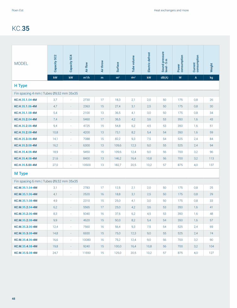
Roen Est Heat exchangers and more
48
KC.35
MODEL
Capa
city
SC2
Capa
city
SC4
Air fl
ow
Air t
hrow
Surf
ace
Tube
vol
ume
Elec
tric
def
rost
Soun
d pr
essu
re
leve
l - 5
m
Pow
er
cons
umpt
ion
Curr
ent
cons
umpt
ion
Wei
ght
kW kW m3/h m m2 dm3 kW dB(A) W A kg
H Type
Fin spacing 4 mm | Tubes Ø9,52 mm 35x35
KC.H.35.1.04-4M 3,7 - 2730 17 18,3 2,1 2,0 50 175 0,8 26
KC.H.35.1.06-4M 4,7 - 2363 15 27,4 3,1 2,5 50 175 0,8 30
KC.H.35.1.08-4M 5,4 - 2100 13 36,5 4,1 3,0 50 175 0,8 34
KC.H.35.2.04-4M 7,4 - 5460 17 36,5 4,2 3,6 53 350 1,6 43
KC.H.35.2.06-4M 9,4 - 4725 15 54,8 6,2 4,5 53 350 1,6 51
KC.H.35.2.08-4M 10,8 - 4200 13 73,1 8,2 5,4 54 350 1,6 59
KC.H.35.3.06-4M 14,1 - 7088 15 82,2 9,3 7,5 54 525 2,4 84
KC.H.35.3.08-4M 16,2 - 6300 13 109,6 12,3 9,0 55 525 2,4 94
KC.H.35.4.06-4M 18,9 - 9450 15 109,6 12,4 9,0 56 700 3,2 96
KC.H.35.4.08-4M 21,6 - 8400 13 146,2 16,4 10,8 56 700 3,2 113
KC.H.35.5.08-4M 27,0 - 10500 13 182,7 20,5 13,2 57 875 4,0 137
M Type
Fin spacing 6 mm | Tubes Ø9,52 mm 35x35
KC.M.35.1.04-4M 3,1 - 2783 17 12,5 2,1 2,0 50 175 0,8 25
KC.M.35.1.06-4M 4,1 - 2520 16 18,8 3,1 2,5 50 175 0,8 29
KC.M.35.1.08-4M 4,9 - 2310 15 25,0 4,1 3,0 50 175 0,8 33
KC.M.35.2.04-4M 6,2 - 5565 17 25,0 4,2 3,6 53 350 1,6 41
KC.M.35.2.06-4M 8,3 - 5040 16 37,6 6,2 4,5 53 350 1,6 48
KC.M.35.2.08-4M 9,9 - 4620 15 50,0 8,2 5,4 54 350 1,6 57
KC.M.35.3.06-4M 12,4 - 7560 16 56,4 9,3 7,5 54 525 2,4 69
KC.M.35.3.08-4M 14,8 - 6930 15 75,0 12,3 9,0 55 525 2,4 74
KC.M.35.4.06-4M 16,6 - 10080 16 75,2 12,4 9,0 56 700 3,2 90
KC.M.35.4.08-4M 19,8 - 9240 15 100,0 16,4 10,8 56 700 3,2 104
KC.M.35.5.08-4M 24,7 - 11550 15 125,0 20,5 13,2 57 875 4,0 127

49
Unit coolers and brine units
MODELCa
paci
ty S
C2
Capa
city
SC4
Air fl
ow
Air t
hrow
Surf
ace
Tube
vol
ume
Elec
tric
def
rost
Soun
d pr
essu
re
leve
l - 5
m
Pow
er
cons
umpt
ion
Curr
ent
cons
umpt
ion
Wei
ght
kW kW m3/h m m2 dm3 kW dB(A) W A kg
L Type
Fin spacing 8 mm | Tubes Ø9,52 mm 35x35KC.L.35.1.04-4M 2,8 1,9 2835 18 9,7 2,1 2,0 50 175 0,8 24
KC.L.35.1.06-4M 3,8 2,5 2625 16 14,4 3,1 2,5 50 175 0,8 27
KC.L.35.1.08-4M 4,7 3,0 2415 15 19,2 4,1 3,0 50 175 0,8 32
KC.L.35.2.04-4M 5,5 3,8 5670 18 19,3 4,2 3,6 53 350 1,6 39
KC.L.35.2.06-4M 7,7 5,0 5250 16 28,8 6,2 4,5 53 350 1,6 45
KC.L.35.2.08-4M 9,4 6,0 4830 15 38,4 8,2 5,4 54 350 1,6 54
KC.L.35.3.06-4M 11,5 7,6 7875 16 43,2 9,3 7,5 54 525 2,4 64
KC.L.35.3.08-4M 14,0 9,0 7245 15 57,6 12,3 9,0 55 525 2,4 70
KC.L.35.4.06-4M 15,4 10,1 10500 16 57,5 12,4 9,0 56 700 3,2 83
KC.L.35.4.08-4M 18,7 12,0 9660 15 76,9 16,4 10,8 56 700 3,2 95
KC.L.35.5.08-4M 23,4 15,0 12075 15 96,1 20,5 13,2 57 875 4,0 116
V Type
Fin spacing 10 mm | Tubes Ø12 mmKC.V.35.1.04-4M 2.9 1.7 2850 18 9.0 3.5 2.0 50 145 0.7 24
KC.V.35.1.06-4M 3.8 2.2 2550 17 13.0 5.0 3 50 145 0.7 28
KC.V.35.2.04-4M 5.8 3.4 5700 18 18.0 7.0 3.6 53 290 1.4 39
KC.V.35.2.06-4M 7.6 4.4 5100 17 26 10.0 4.5 53 290 1.4 45
KC.V.35.3.04-4M 8.7 5.1 8550 18 27 10.5 6.0 55 435 2.1 59
KC.V.35.3.06-4M 11.4 6.6 7650 17 39 15.0 7.5 55 435 2.1 64
KC.V.35.4.06-4M 15.2 8.8 10200 17 52 20.0 9.0 56 580 2.8 77
KC.V.35.4.08-4M 18.2 10.4 9600 16 68 26.0 11 56 580 2.8 90
KC.V.35.5.06-4M 19.0 11.0 12750 17 65 25.0 11.0 57 725 3.5 98
KC.V.35.5.08-4M 22.8 13.0 12000 16 85 33.0 13.2 57 725 3.5 110
I Type
Fin spacing 12 mm | Tubes Ø12 mmKC.I.35.1.04-4M 2.6 1.6 2850 19 7.0 3.5 2.0 50 145 0.7 23
KC.I.35.1.06-4M 3.6 2.1 2600 18 11.0 5.0 3 50 145 0.7 27
KC.I.35.2.04-4M 5.2 3.2 5700 19 14.0 7.0 3.6 53 290 1.4 37
KC.I.35.2.06-4M 7.2 4.2 5200 18 22.0 10.0 4.5 53 290 1.4 42
KC.I.35.3.04-4M 7.8 4.8 8550 19 21 10.5 6.0 55.0 435 2.1 55
KC.I.35.3.06-4M 10.8 6.3 7800 18 33 15.0 7.5 55 435 2.1 60
KC.I.35.4.06-4M 14.4 8.4 10400 18 44 20.0 9.0 56 580 2.8 75
KC.I.35.4.08-4M 17.2 9.8 9800 17 56 26.0 11 56 580 2.8 86
KC.I.35.5.06-4M 18.0 10.5 13000 18 55 25.0 11.0 57 725 3.5 94
KC.I.35.5.08-4M 21.5 12.5 12250 17 70 33.0 13.2 57 725 3.5 109
KC.35

E F
I
INOUT
120
60
40
55
A
B C D
H
Ă
C'
= =
Roen Est Heat exchangers and more
50
KC.45
MODELFan motors
N°
Dimensions ConnectionsØ
drainA B C C’ D E F H I IN OUT
mm
KC.x.45.1.xx 1 1150 155 830 / 155 600 550 640 660 16 22 1”
KC.x.45.2.xx 2 1950 155 1630 / 155 600 550 640 660 16 28 1” ¼
KC.x.45.3.xx 3 2750 155 2430 / 155 600 550 640 660 22 35 1” ½
KC.x.45.4.xx 4 3550 155 3230 1600 155 600 550 640 660 28 42 1” ½
Code Motor Diam. Ø [mm] Supply line
Δ Y
Speed [RPM] Power [W] Current [A] dB (A) 5 m Speed [RPM] Power [W] Current [A] dB (A) 5 m
KC.x.45.x.xx-4T 4 poles 450 400/3/50 1400 590 0.9 50 1180 305 0.55 44
OLD
NEW
Reduced tube diameter

51
Unit coolers and brine units
KC.45
MODEL
4 Poles - Δ - 1400 RPM 4 Poles - Y - 1180 RPM
Surf
ace
Tube
vol
ume
Elec
tric
def
rost
Wat
er d
efro
st
Wei
ght
Capa
city
SC2
Capa
city
SC4
Air fl
ow
Air t
hrow
Soun
d pr
essu
re
leve
l - 5
m
Capa
city
SC2
Capa
city
SC4
Air fl
ow
Air t
hrow
Soun
d pr
essu
re
leve
l - 5
m
kW kW m3/h m dBA 5m kW kW m3/h m dBA 5m m2 dm3 kW l/h kg
H Type
Fin spacing 4 mm | Tubes Ø9,52 mm 35x35
KC.H.45.1.06-4T 8,0 - 4935 24 49 7,1 - 3780 18 43 44,7 4,8 3,6 2700 61
KC.H.45.1.08-4T 9,1 - 4358 22 49 7,9 - 3308 16 43 59,5 6,4 4,8 3400 69
KC.H.45.2.06-4T 16,0 - 9870 24 52 14,2 - 7560 18 46 89,3 9,6 7,2 5400 107
KC.H.45.2.08-4T 18,2 - 8715 22 52 15,8 - 6615 16 46 119 12,8 9,6 6800 122
KC.H.45.3.06-4T 24,0 - 14805 24 54 21,3 - 11340 18 48 134 14,4 10,8 8100 148
KC.H.45.3.08-4T 27,3 - 13073 22 54 23,6 - 9923 16 48 178,5 19,2 14,4 10200 170
KC.H.45.4.06-4T 32,0 - 19740 24 55 28,4 - 15120 18 49 178,6 19,2 14,4 10800 191
KC.H.45.4.08-4T 36,5 - 17430 22 55 31,5 - 13230 16 49 238 25,6 19,2 13600 221
M Type
Fin spacing 6 mm | Tubes Ø9,52 mm 35x35
KC.M.45.1.06-4T 7,3 - 5355 26 49 6,4 - 4043 19 43 30,6 4,8 3,6 2700 58
KC.M.45.1.08-4T 8,6 - 4725 24 49 7,4 - 3570 17 43 40,7 6,4 4,8 3400 65
KC.M.45.2.06-4T 14,6 - 10710 26 52 12,8 - 8085 19 46 61,2 9,6 7,2 5400 100
KC.M.45.2.08-4T 17,1 - 9450 24 52 14,9 - 7140 17 46 81,4 12,8 9,6 6800 113
KC.M.45.3.06-4T 21,9 - 16065 26 54 19,2 - 12128 19 48 91,7 14,4 10,8 8100 139
KC.M.45.3.08-4T 25,7 - 14175 24 54 22,3 - 10710 17 48 122,1 19,2 14,4 10200 158
KC.M.45.4.06-4T 29,3 - 21420 26 55 25,7 - 16170 19 49 122,3 19,2 14,4 10800 179
KC.M.45.4.08-4T 34,2 - 18900 24 55 29,7 - 14280 17 49 162,8 25,6 19,2 13600 204

Roen Est Heat exchangers and more
52
KC.45
MODEL
4 Poles - Δ - 1400 RPM 4 Poles - Y - 1180 RPM
Surf
ace
Tube
vol
ume
Elec
tric
def
rost
Wat
er d
efro
st
Wei
ght
Capa
city
SC2
Capa
city
SC4
Air fl
ow
Air t
hrow
Soun
d pr
essu
re
leve
l - 5
m
Capa
city
SC2
Capa
city
SC4
Air fl
ow
Air t
hrow
Soun
d pr
essu
re
leve
l - 5
m
kW kW m3/h m dBA 5m kW kW m3/h m dBA 5m m2 dm3 kW l/h kg
L Type
Fin spacing 8 mm | Tubes Ø9,52 mm 35x35KC.L.45.1.06-4T 6,5 3,9 5565 26 49 5,9 3,6 4358 19 43 23,5 4,8 3,6 2700 55
KC.L.45.1.08-4T 7,9 4,7 5040 24 49 7,0 4,2 3885 17 43 31,4 6,4 4,8 3400 61
KC.L.45.2.06-4T 13,1 7,9 11130 26 52 11,7 7,2 8715 19 46 47,1 9,6 7,2 5400 94
KC.L.45.2.08-4T 15,8 9,5 10080 24 52 14,0 8,3 7770 17 46 62,7 12,8 9,6 6800 105
KC.L.45.3.06-4T 19,6 11,8 16695 26 54 17,6 10,8 13073 19 48 70,6 14,4 10,8 8100 129
KC.L.45.3.08-4T 23,6 14,2 15120 24 54 20,9 12,5 11655 17 48 94,1 19,2 14,4 10200 145
KC.L.45.4.06-4T 26,1 15,8 22260 26 55 23,4 14,4 17430 19 49 94,2 19,2 14,4 10800 166
KC.L.45.4.08-4T 31,5 18,9 20160 24 55 27,9 16,7 15540 17 49 125,4 25,6 19,2 13600 187
V Type
Fin spacing 10 mm | Tubes Ø12 mmKC.V.45.1.06-4T 6,1 3,7 5670 27 49 5,4 3,4 4463 20 43 20,4 7,4 3,6 2700 52
KC.V.45.1.08-4T 7,5 4,5 5250 25 49 6,5 3,9 4043 18 43 25,7 9,9 4,8 3400 57
KC.V.45.2.06-4T 12,2 7,4 11340 27 52 10,8 6,8 8925 20 46 40,7 14,9 7,2 5400 88
KC.V.45.2.08-4T 15,1 9,0 10500 25 52 13,1 7,9 8085 18 46 51,5 19,8 9,6 6800 98
KC.V.45.3.06-4T 18,2 11,1 17010 27 54 16,2 10,1 13388 20 48 61,1 22,3 10,8 8100 119
KC.V.45.3.08-4T 22,6 13,5 15750 25 54 19,6 11,8 12128 18 48 77,2 29,8 14,4 10200 133
KC.V.45.4.06-4T 24,3 14,9 22680 27 55 21,6 13,5 17850 20 49 81,4 29,8 14,4 10800 154
KC.V.45.4.08-4T 30,2 18,0 21000 25 55 26,1 15,8 16170 18 49 103 39,7 19,2 13600 161
I Type
Fin spacing 12 mm | Tubes Ø12 mmKC.I.45.1.06-4T 5,6 3,5 5880 28 49 5,0 3,2 4568 21 43 16,5 7,4 3,6 2700 49
KC.I.45.1.08-4T 7,0 4,3 5460 26 49 6,2 3,8 4200 19 43 21,9 9,9 4,8 3400 53
KC.I.45.2.06-4T 11,3 7,0 11760 28 52 9,9 6,3 9135 21 46 33,0 14,9 7,2 5400 83
KC.I.45.2.08-4T 14,0 8,6 10920 26 52 12,4 7,7 8400 19 46 43,8 19,8 9,6 6800 91
KC.I.45.3.06-4T 16,9 10,5 17640 28 54 14,9 9,5 13703 21 48 49,5 22,3 10,8 8100 110
KC.I.45.3.08-4T 20,9 12,8 16380 26 54 18,6 11,5 12600 19 48 65,7 29,8 14,4 10200 122
KC.I.45.4.06-4T 22,5 14,0 23520 28 55 19,8 12,6 18270 21 49 66,0 29,8 14,4 10800 142
KC.I.45.4.08-4T 27,9 17,1 21840 26 55 24,8 15,3 16800 19 49 87,6 39,7 19,2 13600 135

AH
B C D
= =
76
40
Ø
C'
I
E F
53
Unit coolers and brine units
IC.50/63
IC.x.50.1.xx 1 1250 155 930 / 155 800 690 810 800 16 28 1” ¼
IC.x.50.2.xx 2 2150 155 1830 / 155 800 690 810 800 22 35 1” ½
IC.x.50.3.xx 3 3150 205 2730 900+900 205 800 690 810 800 28 42 1” ½
IC.x.50.4.xx 4 4050 205 3630 900+1800 205 800 690 810 800 35 54 2”
IC.x.63.2.xx 2 2650 205 2230 / 205 1000 810 1250 920 35 54 2”
IC.x.63.3.xx 3 3750 205 3330 1100+1100 205 1000 810 1250 920 2x28 2x42 2”
IC.x.63.4.xx 4 4850 205 4430 1100+2200 205 1000 810 1250 920 2x35 2x54 2”
MODELFan motors
N°
Dimensions ConnectionsØ
drainA B C C’ D E F H I IN OUT
mm
Code Motor Diam. Ø [mm] Supply line
Δ Y
Speed [RPM] Power [W] Current [A] dB (A) 5 m Speed [RPM] Power [W] Current [A] dB (A) 5 m
IC.x.50.x.xx-4T 4 poles 500 400/3/50 1340 780 1.35 51 1000 550 0.94 44
IC.x.63.x.xx-4T 4 poles 630 400/3/50 1310 2600 4.8 63 1000 1600 2.7 57
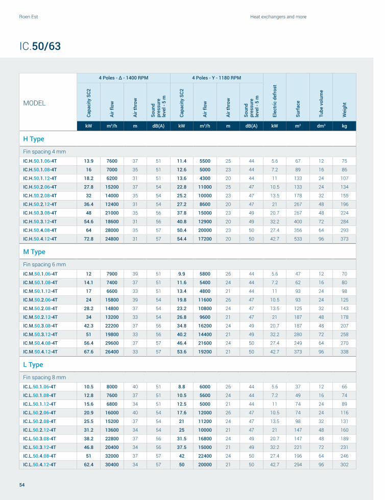
Roen Est Heat exchangers and more
54
IC.50/63
MODEL
4 Poles - Δ - 1400 RPM 4 Poles - Y - 1180 RPM
Elec
tric
def
rost
Surf
ace
Tube
vol
ume
Wei
ght
Capa
city
SC2
Air fl
ow
Air t
hrow
Soun
d pr
essu
re
leve
l - 5
m
Capa
city
SC2
Air fl
ow
Air t
hrow
Soun
d pr
essu
re
leve
l - 5
m
kW m3/h m dB(A) kW m3/h m dB(A) kW m2 dm3 kg
H Type
Fin spacing 4 mm
IC.H.50.1.06-4T 13.9 7600 37 51 11.4 5500 25 44 5.6 67 12 75
IC.H.50.1.08-4T 16 7000 35 51 12.6 5000 23 44 7.2 89 16 86
IC.H.50.1.12-4T 18.2 6200 31 51 13.6 4300 20 44 11 133 24 107
IC.H.50.2.06-4T 27.8 15200 37 54 22.8 11000 25 47 10.5 133 24 134
IC.H.50.2.08-4T 32 14000 35 54 25.2 10000 23 47 13.5 178 32 155
IC.H.50.2.12-4T 36.4 12400 31 54 27.2 8600 20 47 21 267 48 196
IC.H.50.3.08-4T 48 21000 35 56 37.8 15000 23 49 20.7 267 48 224
IC.H.50.3.12-4T 54.6 18600 31 56 40.8 12900 20 49 32.2 400 72 284
IC.H.50.4.08-4T 64 28000 35 57 50.4 20000 23 50 27.4 356 64 293
IC.H.50.4.12-4T 72.8 24800 31 57 54.4 17200 20 50 42.7 533 96 373
M Type
Fin spacing 6 mm
IC.M.50.1.06-4T 12 7900 39 51 9.9 5800 26 44 5.6 47 12 70
IC.M.50.1.08-4T 14.1 7400 37 51 11.6 5400 24 44 7.2 62 16 80
IC.M.50.1.12-4T 17 6600 33 51 13.4 4800 21 44 11 93 24 98
IC.M.50.2.06-4T 24 15800 39 54 19.8 11600 26 47 10.5 93 24 125
IC.M.50.2.08-4T 28.2 14800 37 54 23.2 10800 24 47 13.5 125 32 143
IC.M.50.2.12-4T 34 13200 33 54 26.8 9600 21 47 21 187 48 178
IC.M.50.3.08-4T 42.3 22200 37 56 34.8 16200 24 49 20.7 187 48 207
IC.M.50.3.12-4T 51 19800 33 56 40.2 14400 21 49 32.2 280 72 258
IC.M.50.4.08-4T 56.4 29600 37 57 46.4 21600 24 50 27.4 249 64 270
IC.M.50.4.12-4T 67.6 26400 33 57 53.6 19200 21 50 42.7 373 96 338
L Type
Fin spacing 8 mm
IC.L.50.1.06-4T 10.5 8000 40 51 8.8 6000 26 44 5.6 37 12 66
IC.L.50.1.08-4T 12.8 7600 37 51 10.5 5600 24 44 7.2 49 16 74
IC.L.50.1.12-4T 15.6 6800 34 51 12.5 5000 21 44 11 74 24 89
IC.L.50.2.06-4T 20.9 16000 40 54 17.6 12000 26 47 10.5 74 24 116
IC.L.50.2.08-4T 25.5 15200 37 54 21 11200 24 47 13.5 98 32 131
IC.L.50.2.12-4T 31.2 13600 34 54 25 10000 21 47 21 147 48 160
IC.L.50.3.08-4T 38.2 22800 37 56 31.5 16800 24 49 20.7 147 48 189
IC.L.50.3.12-4T 46.8 20400 34 56 37.5 15000 21 49 32.2 221 72 231
IC.L.50.4.08-4T 51 32000 37 57 42 22400 24 50 27.4 196 64 246
IC.L.50.4.12-4T 62.4 30400 34 57 50 20000 21 50 42.7 294 96 302

55
Unit coolers and brine units
IC.50/63
MODEL
4 Poles - Δ - 1400 RPM 4 Poles - Y - 1180 RPM
Elec
tric
def
rost
Surf
ace
Tube
vol
ume
Wei
ght
Capa
city
SC2
Air fl
ow
Air t
hrow
Soun
d pr
essu
re
leve
l - 5
m
Capa
city
SC2
Air fl
ow
Air t
hrow
Soun
d pr
essu
re
leve
l - 5
m
kW m3/h m dB(A) kW m3/h m dB(A) kW m2 dm3 kg
V Type
Fin spacing 10 mm
IC.V.50.1.06-4T 9.2 8160 41 51 7.8 6050 27 44 5.6 26 12 62
IC.V.50.1.08-4T 11.6 7780 38 51 9.4 5650 25 44 7.2 41 16 68
IC.V.50.1.12-4T 14.5 6900 35 51 11.5 4900 22 44 11 62 24 81
IC.V.50.2.06-4T 18.4 16320 41 54 15.6 12100 27 47 10.5 52 24 108
IC.V.50.2.08-4T 23.1 15560 38 54 18.8 11300 25 47 13.5 83 32 120
IC.V.50.2.12-4T 28.9 13800 35 54 23 9800 22 47 21 124 48 143
IC.V.50.3.08-4T 34.7 23340 38 56 28.2 16950 25 49 20.7 124 48 172
IC.V.50.3.12-4T 43.4 20700 35 56 34.5 14700 22 49 32.2 186 72 206
IC.V.50.4.08-4T 46.3 31120 38 57 37.6 22600 25 50 27.4 166 64 223
IC.V.50.4.12-4T 57.8 27600 35 57 46 19600 22 50 42.7 248 96 267
I Type
Fin spacing 12 mm
IC.I.50.1.06-4T 8.6 8210 42 51 7.4 6100 27 44 5.6 22 12 59
IC.I.50.1.08-4T 10.9 7830 38 51 8.9 5700 25 44 7.2 36 16 63
IC.I.50.1.12-4T 13.8 6950 35 51 10.9 4950 22 44 11 54 24 72
IC.I.50.2.06-4T 17.1 16420 42 54 14.8 12200 27 47 10.5 54 24 100
IC.I.50.2.08-4T 21.8 15660 38 54 17.8 11400 25 47 13.5 73 32 109
IC.I.50.2.12-4T 27.6 13900 35 54 21.8 9900 22 47 21 109 48 127
IC.I.50.3.08-4T 32.7 23490 38 56 26.7 17100 25 49 20.7 109 48 156
IC.I.50.3.12-4T 41.3 20850 35 56 32.7 14850 22 49 32.2 163 72 180
IC.I.50.4.08-4T 43.6 31320 38 57 35.6 22800 25 50 27.4 145 64 200
IC.I.50.4.12-4T 55.1 27800 35 57 43.6 19800 22 50 42.7 218 96 235

Roen Est Heat exchangers and more
56
IC.63
MODEL
4 Poles - Δ - 1310 RPM 4 Poles - Y - 1000 RPM
Elec
tric
def
rost
Surf
ace
Tube
vol
ume
Wei
ght
Capa
city
SC2
Air fl
ow
Air t
hrow
Soun
d pr
essu
re
leve
l - 5
m
Capa
city
SC2
Air fl
ow
Air t
hrow
Soun
d pr
essu
re
leve
l - 5
m
kW m3/h m dB(A) kW m3/h m dB(A) kW m2 dm3 kg
H Type
Fin spacing 4 mm
IC.H.63.2.08-4T 71.2 32600 55 66 58.8 23600 43 60 32.4 350 65 310
IC.H.63.2.10-4T 78.5 30800 52 66 63.4 22400 40 60 37.8 437 80 352
IC.H.63.2.12-4T 82.4 29400 50 66 66.2 21200 38 60 48.6 525 97 392
IC.H.63.3.08-4T 106.8 48900 55 68 88.2 35400 43 62 45 525 98 453
IC.H.63.3.10-4T 117.7 46200 52 68 95.1 33600 40 62 52.5 655 120 514
IC.H.63.3.12-4T 123.6 44100 50 68 99.3 31800 38 62 67.5 787 145 572
IC.H.63.4.08-4T 142.4 65200 55 69 117.6 47200 43 63 61.2 700 130 597
IC.H.63.4.10-4T 157 61600 52 69 126.8 44800 40 63 71.4 874 160 682
IC.H.63.4.12-4T 164.8 58800 50 69 132.4 42400 38 63 91.8 1050 194 755
M Type
Fin spacing 6 mm
IC.M.63.2.08-4T 62.2 34200 58 66 52.7 25200 45 60 32.4 247 65 288
IC.M.63.2.10-4T 70.3 32600 55 66 58.3 23600 42 60 37.8 309 80 325
IC.M.63.2.12-4T 76.9 31200 53 66 62.3 22400 40 60 48.6 371 97 360
IC.M.63.3.08-4T 93.3 51300 58 68 79.1 37800 45 62 45 371 98 420
IC.M.63.3.10-4T 105.4 48900 55 68 87.5 35400 42 62 52.5 463 120 473
IC.M.63.3.12-4T 115.3 46800 53 68 93.4 33600 40 62 67.5 578 145 524
IC.M.63.4.08-4T 124.4 68400 58 69 105.4 50400 45 63 61.2 494 130 553
IC.M.63.4.10-4T 140.6 65200 55 69 116.6 47200 42 63 71.4 618 160 623
IC.M.63.4.12-4T 153.8 62400 53 69 124.6 44800 40 63 91.8 742 194 691
L Type
Fin spacing 8 mm
IC.L.63.2.08-4T 55.8 35000 59 66 47.2 25500 45 60 32.4 196 65 262
IC.L.63.2.10-4T 60.5 33200 56 66 53.5 24400 42 60 37.8 245 80 294
IC.L.63.2.12-4T 64.2 31900 54 66 58.4 23400 40 60 48.6 294 97 326
IC.L.63.3.08-4T 83.8 52500 59 68 70.8 38250 45 62 45 294 98 381
IC.L.63.3.10-4T 90.8 49800 56 68 80.3 36600 42 62 52.5 367 120 426
IC.L.63.3.12-4T 104 47900 54 68 87.6 35100 40 62 67.5 441 145 473
IC.L.63.4.08-4T 111.7 70000 59 69 94.4 51000 45 63 61.2 392 130 501
IC.L.63.4.10-4T 131 66400 56 69 107 48800 42 63 71.4 490 160 560
IC.L.63.4.12-4T 138.7 63800 54 69 116.8 46800 40 63 91.8 588 194 623
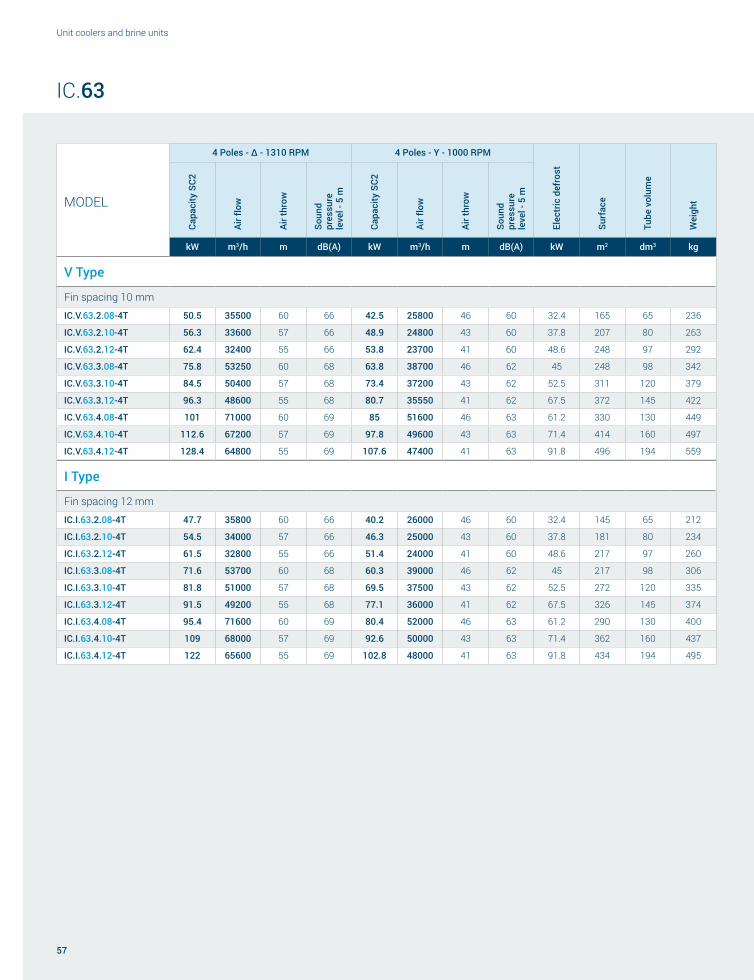
57
Unit coolers and brine units
IC.63
MODEL
4 Poles - Δ - 1310 RPM 4 Poles - Y - 1000 RPM
Elec
tric
def
rost
Surf
ace
Tube
vol
ume
Wei
ght
Capa
city
SC2
Air fl
ow
Air t
hrow
Soun
d pr
essu
re
leve
l - 5
m
Capa
city
SC2
Air fl
ow
Air t
hrow
Soun
d pr
essu
re
leve
l - 5
m
kW m3/h m dB(A) kW m3/h m dB(A) kW m2 dm3 kg
V Type
Fin spacing 10 mm
IC.V.63.2.08-4T 50.5 35500 60 66 42.5 25800 46 60 32.4 165 65 236
IC.V.63.2.10-4T 56.3 33600 57 66 48.9 24800 43 60 37.8 207 80 263
IC.V.63.2.12-4T 62.4 32400 55 66 53.8 23700 41 60 48.6 248 97 292
IC.V.63.3.08-4T 75.8 53250 60 68 63.8 38700 46 62 45 248 98 342
IC.V.63.3.10-4T 84.5 50400 57 68 73.4 37200 43 62 52.5 311 120 379
IC.V.63.3.12-4T 96.3 48600 55 68 80.7 35550 41 62 67.5 372 145 422
IC.V.63.4.08-4T 101 71000 60 69 85 51600 46 63 61.2 330 130 449
IC.V.63.4.10-4T 112.6 67200 57 69 97.8 49600 43 63 71.4 414 160 497
IC.V.63.4.12-4T 128.4 64800 55 69 107.6 47400 41 63 91.8 496 194 559
I Type
Fin spacing 12 mm
IC.I.63.2.08-4T 47.7 35800 60 66 40.2 26000 46 60 32.4 145 65 212
IC.I.63.2.10-4T 54.5 34000 57 66 46.3 25000 43 60 37.8 181 80 234
IC.I.63.2.12-4T 61.5 32800 55 66 51.4 24000 41 60 48.6 217 97 260
IC.I.63.3.08-4T 71.6 53700 60 68 60.3 39000 46 62 45 217 98 306
IC.I.63.3.10-4T 81.8 51000 57 68 69.5 37500 43 62 52.5 272 120 335
IC.I.63.3.12-4T 91.5 49200 55 68 77.1 36000 41 62 67.5 326 145 374
IC.I.63.4.08-4T 95.4 71600 60 69 80.4 52000 46 63 61.2 290 130 400
IC.I.63.4.10-4T 109 68000 57 69 92.6 50000 43 63 71.4 362 160 437
IC.I.63.4.12-4T 122 65600 55 69 102.8 48000 41 63 91.8 434 194 495

Roen Est Heat exchangers and more
58

59
Unit coolers and brine units

Roen Est Heat exchangers and more
60
FRUIT COOLERS350 / 450 / 500 FC Series
IT
ØØ Diametri motore disponibili: 350 mm, 450 mm e 500 mmØØ Numero motori disponibile:
¬ diametro motore 350 mm: da 3 a 5 motori ¬ diametro motore 450 mm: da 2 a 5 motori ¬ diametro motore 500 mm: da 3 a 5 motori
ØØ Passi alette disponibili: 6 mm, 7 mm, 8 mmØØ Tensione motori:
¬ 230 V / 1 / 50 Hz per diametro 350 mm ¬ 400 V / 3 / 50 Hz per diametro 450 mm e 500 mm
ØØ Grado di protezione motori: ¬ diametro 350 mm - IP44 ¬ diametro 450 mm, 500 mm - IP54
EN
ØØ Available fan motor diameters: 350 mm, 450 mm and 500 mmØØ Available number of fan motors:
¬ fan motor diameter 350 mm: from 3 to 5 motors ¬ fan motor diameter 450 mm: from 2 to 5 motors ¬ fan motor diameter 500 mm: from 3 to 5 motors
ØØ Available fin spacing: 6 mm, 7 mm and 8 mmØØ Fan motor voltage:
¬ 230 V / 1 / 50 Hz for diameter 350 mm ¬ 400 V / 3 / 50 Hz for diameter 450 mm and 500 mm
ØØ Fan motor protection class: ¬ diameter 350 mm - IP44 ¬ diameter 450 mm, 500 mm - IP54
DE
ØØ Verfügbare Motordurchmesser: 350 mm, 450 mm und 500 mmØØ Verfügbare Motorenanzahl:
¬ Motordurchmesser 350 mm: von 3 bis 5 Motoren ¬ Motordurchmesser 450 mm: von 2 bis 5 Motoren ¬ Motordurchmesser 500 mm: von 3 bis 5 Motoren
ØØ Abstand der Lamellenabstand: 6 mm, 7 mm und 8 mmØØ Motorspannung:
¬ 230 V / 1 / 50 Hz für Durchmesser 350 mm ¬ 400 V / 3 / 50 Hz für Durchmesser 450 mm und 500 mm
ØØ Schutzart der Motoren: ¬ Durchmesser 350 mm - IP44 ¬ Durchmesser 450 mm, 500 mm - IP54

61
Unit coolers and brine units
ES
ØØ Diámetros motores disponibles: 350 mm, 450 mm y 500 mmØØ Número motores disponible:
¬ diámetro motor 350 mm: de 3 a 5 motores ¬ diámetro motor 450 mm: de 2 a 5 motores ¬ diámetro motor 500 mm: de 3 a 5 motores
ØØ Pasos de aleta disponibles: 6 mm, 7 mm y 8 mmØØ Tensión motores:
¬ 230 V / 1 / 50 Hz para diámetro 350 mm ¬ 400 V / 3 / 50 Hz para diámetro 450 mm y 500 mm
ØØ Grado de protección motores: ¬ diámetro 350 mm - IP44 ¬ diámetro 450 mm, 500 mm - IP54
FR
ØØ Diamètres moteurs disponibles : 350 mm, 450 mm et 500 mmØØ Nombre de moteurs disponible :
¬ diamètre moteur 350 mm: de 3 à 5 moteurs ¬ diamètre moteur 450 mm: de 2 à 5 moteurs ¬ diamètre moteur 500 mm: de 3 à 5 moteurs
ØØ Pas ailettes disponibles : 6 mm, 7 mm et 8 mmØØ Tension moteurs :
¬ 230 V / 1 / 50 Hz pour diamètre 350 mm ¬ 400 V / 3 / 50 Hz pour diamètre 450 mm et 500 mm
ØØ Indice de protection moteurs : ¬ diamètre 350 mm - IP44 ¬ diamètre 450 mm, 500 mm - IP54
RU
ØØ Диаметр двигателей: 350 мм, 450 мм и 500 ммØØ Количество двигателей:
¬ диаметр двигателя 350 мм: от 3 до 5 двигателей ¬ диаметр двигателя 450 мм: от 2 до 5 двигателей ¬ диаметр двигателя 500 мм: от 3 до 5 двигателей
ØØ Шаг ребер: 6 мм, 7 мм и 8 ммØØ Напряжение двигателей:
¬ 230 В / 1 / 50 Гц для диаметра 350 мм ¬ 400 В / 3 / 50 Гц для диаметра 450 мм и 500 мм
ØØ Степень защиты двигателей: ¬ Диаметр 350 мм - IP44 ¬ Диаметр 450 мм, 500 мм – IP54
Fruit coolers Obstkühler
Évaporateurs pour fruits et légumesFruit coolers
Охладители для фруктов
BLOWING FANS, VERSION
ON REQUEST
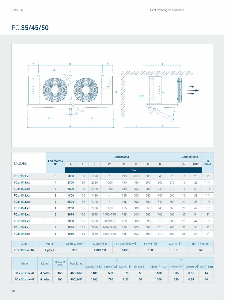
A
B C D
E F
I
Ø
C'
INOUT
= =H
Roen Est Heat exchangers and more
62
FC.35/45/50
MODELFan motors
N°
Dimensions ConnectionsØ
drainA B C C’ D E F H I IN OUT
mm
FC.x.35.3.xx 3 1800 130 1520 / 130 450 500 540 570 16 28 1”
FC.x.35.4.xx 4 2300 130 2020 1000 130 450 500 540 570 16 28 1” ¼
FC.x.35.5.xx 5 2800 130 2520 1000 130 450 500 540 570 16 28 1” ¼
FC.x.45.2.xx 2 1800 155 1480 / 155 600 550 740 660 16 28 1” ¼
FC.x.45.3.xx 3 2525 155 2205 / 155 600 550 740 660 22 35 1” ½
FC.x.45.4.xx 4 3250 155 2930 1450 155 600 550 740 660 28 42 1” ½
FC.x.45.5.xx 5 3975 155 3655 1450+725 155 600 550 740 660 35 54 2”
FC.x.50.3.xx 3 3050 155 2730 900+900 155 800 690 810 800 28 42 1” ½
FC.x.50.4.xx 4 3950 155 3630 900+1800 155 800 690 810 800 35 54 2”
FC.x.50.5.xx 5 4850 155 4530 1800+900 155 800 690 810 800 35 54 2”
Code Motor Diam. Ø [mm] Supply line
Δ Y
Speed [RPM] Power [W] Current [A] dB (A) 5 m Speed [RPM] Power [W] Current [A] dB (A) 5 m
FC.x.45.x.xx-4T 4 poles 450 400/3/50 1400 590 0.9 50 1180 305 0.55 44
FC.x.50.x.xx-4T 4 poles 500 400/3/50 1340 780 1.35 51 1000 550 0.94 44
Code Motor Diam. Ø [mm] Supply line Fan Speed [RPM] Power [W] Current [A] dB(A) 5 meter
FC.x.35.x.xx-4M 4 poles 350 230/1/50 1450 180 0.7 50

63
Unit coolers and brine units
FC.35/45/50
MODELCa
paci
ty S
C2
Air fl
ow
Air t
hrow
Surf
ace
Tube
vol
ume
Elec
tric
def
rost
Fan
mot
ors
Fan
spee
d
Soun
d pr
essu
re
leve
l - 5
m
Pow
er
cons
umpt
ion
Curr
ent
cons
umpt
ion
Wei
ght
kW m3/h m m2 dm3 kW N° RPM dB(A) W A kg
M Type
Fin spacing 6 mm
FC.M.35.3.08-4M 9.9 6510 15 67 9 4.5 3 1450 55 540 2.1 67
FC.M.35.4.08-4M 13.4 8680 15 89 12 6 4 1450 56 720 2.8 88
FC.M.35.5.08-4M 16.7 10850 15 112 15 7.6 5 1450 57 900 3.5 107
FC.M.45.2.08-4T 14.5 10200 25 92 12 6.6 2 1400 53 1180 1.8 101
FC.M.45.3.08-4T 20.9 14400 25 134 18 9.6 3 1400 55 1770 2.7 140
FC.M.45.4.08-4T 28.3 19200 25 178 24 12.6 4 1400 56 2360 3.6 180
FC.M.45.5.08-4T 35.4 24000 25 222 30 15.6 5 1400 57 2950 4.5 221
FC.M.50.3.10-4T 36.1 21600 35 224 30 16.1 3 1340 56 2340 4.1 235
FC.M.50.4.10-4T 50.2 31200 35 298 40 21.4 4 1340 57 3120 5.4 310
FC.M.50.5.10-4T 63.4 39800 35 373 50 23.8 5 1340 58 3900 6.8 385
N Type
Fin spacing 7 mm
FC.N.35.3.08-4M 9.2 6590 15 59 9 4.5 3 1450 55 540 2.1 64
FC.N.35.4.08-4M 12.2 8780 15 78 12 6 4 1450 56 720 2.8 85
FC.N.35.5.08-4M 15.5 11000 15 97 15 7.6 5 1450 57 900 3.5 100
FC.N.45.2.08-4T 13.5 10500 25 78 12 6.6 2 1400 53 1180 1.8 97
FC.N.45.3.08-4T 19.7 14700 25 116 18 9.6 3 1400 55 1770 2.7 132
FC.N.45.4.08-4T 26.3 19500 25 151 24 12.6 4 1400 56 2360 3.6 172
FC.N.45.5.08-4T 32.8 24300 25 188 30 15.6 5 1400 57 2950 4.5 210
FC.N.50.3.10-4T 33.8 21800 35 195 30 16.1 3 1340 56 2340 4.1 195
FC.N.50.4.10-4T 46.6 31500 35 260 40 21.4 4 1340 57 3120 5.4 268
FC.N.50.5.10-4T 59 40300 35 325 50 23.8 5 1340 58 3900 6.8 330
L Type
Fin spacing 8 mm
FC.L.35.3.08-4M 8.8 6660 15 53 9 4.5 3 1450 55 540 2.1 61
FC.L.35.4.08-4M 11.8 8880 15 70 12 6 4 1450 56 720 2.8 79
FC.L.35.5.08-4M 14.7 11100 15 88 15 7.6 5 1450 57 900 3.5 96
FC.L.45.2.08-4T 13 10800 26 71 12 6.6 2 1400 53 1180 1.8 93
FC.L.45.3.08-4T 18.8 14900 26 105 18 9.6 3 1400 55 1770 2.7 127
FC.L.45.4.08-4T 25.1 19800 26 142 24 12.6 4 1400 56 2360 3.6 163
FC.L.45.5.08-4T 31.6 24700 26 177 30 15.6 5 1400 57 2950 4.5 200
FC.L.50.3.10-4T 32.4 22000 36 178 30 16.1 3 1340 56 2340 4.1 148
FC.L.50.4.10-4T 44.9 31800 36 230 40 21.4 4 1340 57 3120 5.4 210
FC.L.50.5.10-4T 56.9 40800 36 289 50 23.8 5 1340 58 3900 6.8 278
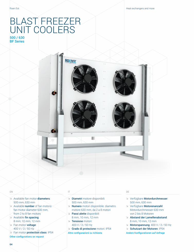
Roen Est Heat exchangers and more
64
BLAST FREEZER UNIT COOLERS500 / 630 BF Series
IT
ØØ Diametri motore disponibili: 500 mm, 630 mmØØ Numero motori disponibile: diametro
motore 630 mm, da 2 a 8 motoriØØ Passi alette disponibili:
8 mm, 10 mm, 12 mmØØ Tensione motori:
400 V / 3 / 50 HzØØ Grado di protezione motori: IP54
Altre configurazioni su richiesta
EN
ØØ Available fan motor diameters: 500 mm, 630 mmØØ Available number of fan motors:
fan motor diameter 630 mm, from 2 to 8 fan motorsØØ Available fin spacing:
8 mm, 10 mm, 12 mmØØ Fan motor voltage:
400 V / 3 / 50 HzØØ Fan motor protection class: IP54
Other configurations on request
DE
ØØ Verfügbare Motordurchmesser: 500 mm, 630 mmØØ Verfügbare Motorenanzahl:
Motordurchmesser 630 mm von 2 bis 8 MotorenØØ Abstand der Lamellenabstand:
8 mm, 10 mm, 12 mmØØ Motorspannung: 400 V / 3 / 50 Hz ØØ Schutzart der Motoren: IP54
Andere Konfigurationen auf Anfrage

65
Unit coolers and brine units
ES
ØØ Diámetros motores disponibles: 500 mm, 630 mmØØ Número motores disponible:
diámetro motor 630 mm, de 2 a 8 motoresØØ Pasos de aleta disponibles:
8 mm, 10 mm, 12 mmØØ Tensión motores: 400 V / 3 / 50 HzØØ Grado de protección motores: IP54
Otras configuraciones a petición
FR
ØØ Diamètres moteurs disponibles : 500 mm, 630 mmØØ Nombre de moteurs disponible :
diamètre moteur 630 mm, de 2 à 8 moteursØØ Pas ailettes disponibles :
8 mm, 10 mm, 12 mmØØ Tension moteurs : 400 V / 3 / 50 HzØØ Indice de protection moteurs : IP54
Autres configurations sur demande
RU
ØØ Диаметр двигателей: 500 мм, 630 ммØØ Количество двигателей:
диаметр двигателя 630 мм, от 2 до 8 двигателейØØ Шаг ребер: 8 мм, 10 мм, 12 ммØØ Напряжение двигателей:
400 В / 3 / 50 ГцØØ Степень защиты двигателей: IP54
Другие конфигурации по запросу
Blast freezer unit coolersSchockfrosteinheit
Blast freezer unit coolersBlast freezer unit coolers
Воздухоохладители шоковой заморозки

i
Ă
F
H
IN
H'
D DC
A
E
Roen Est Heat exchangers and more
66
BF.50/63
MODELFan motors
N°
Dimensions ConnectionsØ
drainA B C C’ D E F H I IN OUT
mm
BF.50
BF.x.50.2.xx 2 1365 210 930 / 210 800 780 1550 800 35 54 2”
BF.x.50.4.xx 4 2265 210 1830 900 210 800 780 1550 800 2x28 2x42 2”
BF.x.50.6.xx 6 3165 210 2730 900+900 210 800 780 1550 800 2x35 2x54 2"
BF.x.50.8.xx 8 4065 210 3630 900+1800 210 800 780 1550 800 2x35 2x54 3”
BF.63
BF.x.63.2.xx 2 1550 205 1130 / 205 1000 890 2170 920 35 54 2”
BF.x.63.4.xx 4 2650 205 2230 1100 205 1000 890 2170 920 2x28 2x42 2”
BF.x.63.6.xx 6 3750 205 3330 1100+1100 205 1000 890 2170 920 2x35 2x54 3"
BF.x.63.8.xx 8 4850 205 4430 1100+2200 205 1000 890 2170 920 2x35 2x54 3”
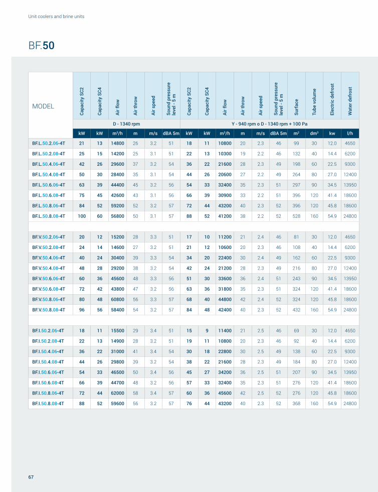
67
Unit coolers and brine units
BF.50
MODEL
Capa
city
SC2
Capa
city
SC4
Air fl
ow
Air t
hrow
Air s
peed
Soun
d pr
essu
re
leve
l - 5
m
Capa
city
SC2
Capa
city
SC4
Air fl
ow
Air t
hrow
Air s
peed
Soun
d pr
essu
re
leve
l - 5
m
Surf
ace
Tube
vol
ume
Elec
tric
def
rost
Wat
er d
efro
st
D - 1340 rpm Y - 940 rpm o D - 1340 rpm + 100 Pa
kW kW m3/h m m/s dBA 5m kW kW m3/h m m/s dBA 5m m2 dm3 kw l/h
BF.L.50.2.06-4T 21 13 14800 26 3.2 51 18 11 10800 20 2.3 46 99 30 12.0 4650
BF.L.50.2.08-4T 25 15 14200 25 3.1 51 22 13 10300 19 2.2 46 132 40 14.4 6200
BF.L.50.4.06-4T 42 26 29600 37 3.2 54 36 22 21600 28 2.3 49 198 60 22.5 9300
BF.L.50.4.08-4T 50 30 28400 35 3.1 54 44 26 20600 27 2.2 49 264 80 27.0 12400
BF.L.50.6.06-4T 63 39 44400 45 3.2 56 54 33 32400 35 2.3 51 297 90 34.5 13950
BF.L.50.6.08-4T 75 45 42600 43 3.1 56 66 39 30900 33 2.2 51 396 120 41.4 18600
BF.L.50.8.06-4T 84 52 59200 52 3.2 57 72 44 43200 40 2.3 52 396 120 45.8 18600
BF.L.50.8.08-4T 100 60 56800 50 3.1 57 88 52 41200 38 2.2 52 528 160 54.9 24800
BF.V.50.2.06-4T 20 12 15200 28 3.3 51 17 10 11200 21 2.4 46 81 30 12.0 4650
BF.V.50.2.08-4T 24 14 14600 27 3.2 51 21 12 10600 20 2.3 46 108 40 14.4 6200
BF.V.50.4.06-4T 40 24 30400 39 3.3 54 34 20 22400 30 2.4 49 162 60 22.5 9300
BF.V.50.4.08-4T 48 28 29200 38 3.2 54 42 24 21200 28 2.3 49 216 80 27.0 12400
BF.V.50.6.06-4T 60 36 45600 48 3.3 56 51 30 33600 36 2.4 51 243 90 34.5 13950
BF.V.50.6.08-4T 72 42 43800 47 3.2 56 63 36 31800 35 2.3 51 324 120 41.4 18600
BF.V.50.8.06-4T 80 48 60800 56 3.3 57 68 40 44800 42 2.4 52 324 120 45.8 18600
BF.V.50.8.08-4T 96 56 58400 54 3.2 57 84 48 42400 40 2.3 52 432 160 54.9 24800
BF.I.50.2.06-4T 18 11 15500 29 3.4 51 15 9 11400 21 2.5 46 69 30 12.0 4650
BF.I.50.2.08-4T 22 13 14900 28 3.2 51 19 11 10800 20 2.3 46 92 40 14.4 6200
BF.I.50.4.06-4T 36 22 31000 41 3.4 54 30 18 22800 30 2.5 49 138 60 22.5 9300
BF.I.50.4.08-4T 44 26 29800 39 3.2 54 38 22 21600 28 2.3 49 184 80 27.0 12400
BF.I.50.6.06-4T 54 33 46500 50 3.4 56 45 27 34200 36 2.5 51 207 90 34.5 13950
BF.I.50.6.08-4T 66 39 44700 48 3.2 56 57 33 32400 35 2.3 51 276 120 41.4 18600
BF.I.50.8.06-4T 72 44 62000 58 3.4 57 60 36 45600 42 2.5 52 276 120 45.8 18600
BF.I.50.8.08-4T 88 52 59600 56 3.2 57 76 44 43200 40 2.3 52 368 160 54.9 24800
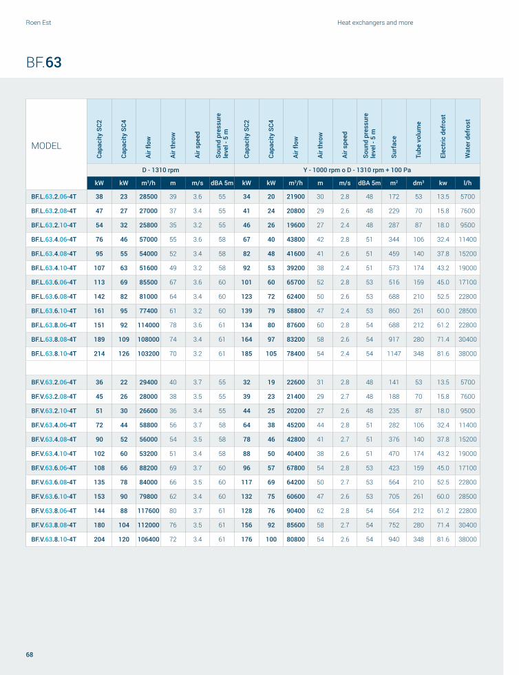
Roen Est Heat exchangers and more
68
BF.63
MODEL
Capa
city
SC2
Capa
city
SC4
Air fl
ow
Air t
hrow
Air s
peed
Soun
d pr
essu
re
leve
l - 5
m
Capa
city
SC2
Capa
city
SC4
Air fl
ow
Air t
hrow
Air s
peed
Soun
d pr
essu
re
leve
l - 5
m
Surf
ace
Tube
vol
ume
Elec
tric
def
rost
Wat
er d
efro
st
D - 1310 rpm Y - 1000 rpm o D - 1310 rpm + 100 Pa
kW kW m3/h m m/s dBA 5m kW kW m3/h m m/s dBA 5m m2 dm3 kw l/h
BF.L.63.2.06-4T 38 23 28500 39 3.6 55 34 20 21900 30 2.8 48 172 53 13.5 5700
BF.L.63.2.08-4T 47 27 27000 37 3.4 55 41 24 20800 29 2.6 48 229 70 15.8 7600
BF.L.63.2.10-4T 54 32 25800 35 3.2 55 46 26 19600 27 2.4 48 287 87 18.0 9500
BF.L.63.4.06-4T 76 46 57000 55 3.6 58 67 40 43800 42 2.8 51 344 106 32.4 11400
BF.L.63.4.08-4T 95 55 54000 52 3.4 58 82 48 41600 41 2.6 51 459 140 37.8 15200
BF.L.63.4.10-4T 107 63 51600 49 3.2 58 92 53 39200 38 2.4 51 573 174 43.2 19000
BF.L.63.6.06-4T 113 69 85500 67 3.6 60 101 60 65700 52 2.8 53 516 159 45.0 17100
BF.L.63.6.08-4T 142 82 81000 64 3.4 60 123 72 62400 50 2.6 53 688 210 52.5 22800
BF.L.63.6.10-4T 161 95 77400 61 3.2 60 139 79 58800 47 2.4 53 860 261 60.0 28500
BF.L.63.8.06-4T 151 92 114000 78 3.6 61 134 80 87600 60 2.8 54 688 212 61.2 22800
BF.L.63.8.08-4T 189 109 108000 74 3.4 61 164 97 83200 58 2.6 54 917 280 71.4 30400
BF.L.63.8.10-4T 214 126 103200 70 3.2 61 185 105 78400 54 2.4 54 1147 348 81.6 38000
BF.V.63.2.06-4T 36 22 29400 40 3.7 55 32 19 22600 31 2.8 48 141 53 13.5 5700
BF.V.63.2.08-4T 45 26 28000 38 3.5 55 39 23 21400 29 2.7 48 188 70 15.8 7600
BF.V.63.2.10-4T 51 30 26600 36 3.4 55 44 25 20200 27 2.6 48 235 87 18.0 9500
BF.V.63.4.06-4T 72 44 58800 56 3.7 58 64 38 45200 44 2.8 51 282 106 32.4 11400
BF.V.63.4.08-4T 90 52 56000 54 3.5 58 78 46 42800 41 2.7 51 376 140 37.8 15200
BF.V.63.4.10-4T 102 60 53200 51 3.4 58 88 50 40400 38 2.6 51 470 174 43.2 19000
BF.V.63.6.06-4T 108 66 88200 69 3.7 60 96 57 67800 54 2.8 53 423 159 45.0 17100
BF.V.63.6.08-4T 135 78 84000 66 3.5 60 117 69 64200 50 2.7 53 564 210 52.5 22800
BF.V.63.6.10-4T 153 90 79800 62 3.4 60 132 75 60600 47 2.6 53 705 261 60.0 28500
BF.V.63.8.06-4T 144 88 117600 80 3.7 61 128 76 90400 62 2.8 54 564 212 61.2 22800
BF.V.63.8.08-4T 180 104 112000 76 3.5 61 156 92 85600 58 2.7 54 752 280 71.4 30400
BF.V.63.8.10-4T 204 120 106400 72 3.4 61 176 100 80800 54 2.6 54 940 348 81.6 38000

69
Unit coolers and brine units
BF.63
MODEL
Capa
city
SC2
Capa
city
SC4
Air fl
ow
Air t
hrow
Air s
peed
Soun
d pr
essu
re
leve
l - 5
m
Capa
city
SC2
Capa
city
SC4
Air fl
ow
Air t
hrow
Air s
peed
Soun
d pr
essu
re
leve
l - 5
m
Surf
ace
Tube
vol
ume
Elec
tric
def
rost
Wat
er d
efro
st
D - 1310 rpm Y - 1000 rpm o D - 1310 rpm + 100 Pa
kW kW m3/h m m/s dBA 5m kW kW m3/h m m/s dBA 5m m2 dm3 kw l/h
BF.I.63.2.06-4T 33 20 30000 41 3.8 55 29 17 23100 32 2.9 48 120 53 13.5 5700
BF.I.63.2.08-4T 41 24 28600 39 3.6 55 35 21 21900 30 2.8 48 160 70 15.8 7600
BF.I.63.2.10-4T 46 27 27200 37 3.4 55 40 23 20600 28 2.6 48 200 87 18.0 9500
BF.I.63.4.06-4T 66 40 60000 58 3.8 58 58 35 46200 45 2.9 51 240 106 32.4 11400
BF.I.63.4.08-4T 82 47 57200 55 3.6 58 71 42 43800 42 2.8 51 320 140 37.8 15200
BF.I.63.4.10-4T 93 55 54400 52 3.4 58 80 46 41200 39 2.6 51 400 174 43.2 19000
BF.I.63.6.06-4T 98 60 90000 71 3.8 60 87 52 69300 55 2.9 53 360 159 45.0 17100
BF.I.63.6.08-4T 123 71 85800 67 3.6 60 106 63 65700 52 2.8 53 479 210 52.5 22800
BF.I.63.6.10-4T 139 82 81600 64 3.4 60 120 68 61800 48 2.6 53 599 261 60.0 28500
BF.I.63.8.06-4T 131 80 120000 82 3.8 61 116 69 92400 64 2.9 54 479 212 61.2 22800
BF.I.63.8.08-4T 164 95 114400 78 3.6 61 142 84 87600 60 2.8 54 639 280 71.4 30400
BF.I.63.8.10-4T 186 109 108800 74 3.4 61 160 91 82400 56 2.6 54 799 348 81.6 38000

Roen Est Heat exchangers and more
70
CENTRIFUGAL UNIT COOLERSUC Series
IT
TIPOLOGIAAerorefrigeranti con ventilatori centrifughiQuesti modelli possono considerarsi delle unità di trattamento aria da installare all’interno dei locali da condizionare o refrigerare.
Utilizzano ventilatori centrifughi che, alle portate d’aria indicate, forniscono la pressione statica necessaria per le canalizzazioni normalmente applicate. Inoltre possono essere dotati di doppia batteria per freddo + caldo per raffreddamento, riscaldamento e controllo dell’umidità.
Oltre all’utilizzo in celle frigorifere, sono comunemente applicati in abbinamento a canalizzazioni aria per condizionare locali di logistiche, sale lavorazioni, grandi ambienti e aree dedicate alla stagionatura.
DE
TYPLuftverdampfer mit RadialgebläseBei diesen Modellen handelt es sich um Lüftungsanlagen, die in den zu konditionierenden oder zu kühlenden Räumen installiert werden.
Es werden Radialgebläse eingesetzt, die innerhalb der eingestellten Luftströmung für den für übliche Leitungen benötigten statischen Druck sorgen. Zudem können sie mit einem Doppelwärmetauscher zum Kühlen, Heizen und zur Feuchtigkeitskontrolle ausgestattet werden.
Neben Kühlhäusern werden sie üblicherweise zusammen mit Luftleitungen für die Konditionierung von Logistikräumen, Fertigungshallen, großen Räumen und Reifelagern eingesetzt.
EN
TYPECentrifugal fan air coolersThese models are air handling units to be installed within premises to be air conditioned or refrigerated.
They are equipped with centrifugal fan motors that, at specific air flow rates, provide the static pressure required by the common ducts in use. They can also be equipped with a double cold + heat coil for cooling, heating, and humidity control.
In addition to use in cold storage rooms, these units are commonly used in combination with air ducts to air condition logistics facilities, processing rooms, large premises, and curing rooms.
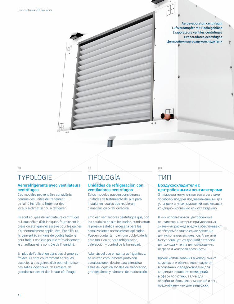
71
Unit coolers and brine units
Aeroevaporatori centrifughiLuftverdampfer mit RadialgebläseÉvaporateurs ventilés centrifuges
Evaporadores centrífugos Центробежные воздухоохладители
FR
TYPOLOGIEAéroréfrigérants avec ventilateurs centrifugesCes modèles peuvent être considérés comme des unités de traitement de l’air à installer à l’intérieur des locaux à climatiser ou à réfrigérer.
Ils sont équipés de ventilateurs centrifuges qui, aux débits d’air indiqués, fournissent la pression statique nécessaire pour les gaines d’air normalement appliquées. Par ailleurs, ils peuvent être munis de double batterie pour froid + chaleur, pour le refroidissement, le chauffage et le contrôle de l’humidité.
En plus de l’utilisation dans des chambres froides, ils sont couramment appliqués associés à des gaines d’air pour climatiser des salles logistiques, des ateliers, de grands espaces et des locaux d’affinage.
ES
TIPOLOGÍAUnidades de refrigeración con ventiladores centrífugosEstos modelos pueden considerarse unidades de tratamiento del aire para instalar en locales que requieran climatización o refrigeración.
Emplean ventiladores centrífugos que, con los caudales de aire indicados, suministran la presión estática necesaria para las canalizaciones normalmente aplicadas. Pueden contar también con doble batería para frío + calor, para refrigeración, calefacción y control de la humedad.
Además del uso en cámaras frigoríficas, se utilizan comúnmente junto con canalizaciones de aire para climatizar salas de logística, locales de elaboración, grandes áreas y cámaras de maduración.
RU
ТИПВоздухоохладители с центробежными вентиляторамиЭти модели могут считаться агрегатами обработки воздуха, предназначенными для установки внутри помещений, подлежащих кондиционированию или охлаждению.
В них используются центробежные вентиляторы, которые при указанных значениях расхода воздуха обеспечивают необходимое статическое давление для используемых каналов. Агрегаты могут оснащаться двойной батареей для холода + тепла для охлаждения, нагрева и контроля влажности.
Кроме использования в холодильных камерах они обычно используются в сочетании с воздуховодами для кондиционирования помещений в сфере логистики, залов для обработки, больших помещений и зон, предназначенных для выдержки.

A B C
Roen Est Heat exchangers and more
72
UC.25/26/28/35/38/45/56/63
MODEL
Dimensions
A F H
mm
UC.x.25.1.xx 1315 1206 875
UC.x.26.1.xx 1440 1206 945
UC.x.28.1.xx 1615 1206 945
UC.x.35.1.xx 1715 1206 1085
UC.x.38.1.xx 2165 1250 1085
UC.x.45.1.xx 2165 1300 1295
UC.x.45.1.xx 2515 1550 1295
UC.x.50.1.xx 2515 1550 1505
UC.x.56.1.xx 2915 1690 1505
UC.x.63.1.xx 2915 1690 1715
MODEL
Dimensions
A F H
mm
UC.x.25.2.xx 1915 1206 875
UC.x.26.2.xx 2165 1206 945
UC.x.28.2.xx 2515 1206 945
UC.x.35.2.xx 2715 1206 1085
UC.x.38.2.xx 3615 1250 1085
UC.x.45.2.xx 3615 1300 1295
UC.x.45.2.xx 4315 1550 1295
UC.x.50.2.xx 4315 1550 1505
UC.x.56.2.xx 5115 1690 1505
UC.x.63.2.xx 5115 1690 1715

73
Unit coolers and brine units
UC.25/26/28/35/38/45/56/63
MODELCa
paci
ty S
C1
ΔTi
=10°
K
Air fl
ow
Stat
ic p
ress
ure
Dyn
amic
pre
ssur
e
Air t
hrow
Surf
ace
Tube
vol
ume
Volta
ge fa
ns
Fans
pow
er
Curr
ent
cons
umpt
ion
Soun
d pr
essu
re
leve
l - 5
m
Elec
tric
def
rost
kW m3/h Pa Pa m m2 dm3 V kW A dB(A) kW
Single fan
H Type Fin spacing 4 mmUC.H.25.1.08 10.3 2500 200 80 20 57 9.5 230/1 1.2 5.0 50 3.0
UC.H.26.1.08 14.9 3750 210 40 21 76 12.8 230/1 1.1 5.0 51 3.6
UC.H.28.1.08 19.7 5000 250 80 29 94 15.9 400/3 2.1 3.7 60 4.8
UC.H.35.1.08 28.2 7500 200 60 33 126 21.2 400/3 3.0 5.2 58 6.8
UC.H.38.1.08 39.1 10000 230 140 46 182 30.8 400/3 4.4 6.0 61 10.1
UC.H.45.1.08 49.8 13000 230 110 50 228 38.4 400/3 3.5 6.5 62 10.1
UC.H.46.1.08 61.5 16000 230 130 58 283 47.7 400/3 4.8 8.3 61 13.5
UC.H.50.1.08 75.8 20000 250 130 64 340 57.3 400/3 6.4 11.2 62 18.0
UC.H.56.1.08 94.6 25000 300 120 70 415 70.0 400/3 8.6 16.2 63 21.6
UC.H.63.1.08 112.5 30000 260 120 76 484 81.7 400/3 8.6 16.2 60 21.6
M TypeFin spacing 6 mmUC.M.25.1.08 9.2 2500 210 80 20 39 9.5 230/1 1.2 5.0 50 3.0
UC.M.26.1.08 13.3 3750 220 40 21 52 12.8 230/1 1.1 5.0 51 3.6
UC.M.28.1.08 17.6 5000 260 80 29 65 15.9 400/3 2.1 3.7 60 4.8
UC.M.35.1.08 25.1 7500 210 60 33 87 21.2 400/3 3.0 5.2 58 6.8
UC.M.38.1.08 34.8 10000 240 140 46 126 30.8 400/3 4.4 6.0 61 10.1
UC.M.45.1.08 44.3 13000 240 110 50 157 38.4 400/3 3.5 6.5 62 10.1
UC.M.46.1.08 54.8 16000 240 130 58 195 47.7 400/3 4.8 8.3 61 13.5
UC.M.50.1.08 67.5 20000 260 130 64 235 57.3 400/3 6.4 11.2 62 18.0
UC.M.56.1.08 84.2 25000 310 120 70 286 70.0 400/3 8.6 16.2 63 21.6
UC.M.63.1.08 100.1 30000 270 120 76 334 81.7 400/3 8.6 16.2 60 21.6
L TypeFin spacing 8 mmUC.L.25.1.08 8.1 2500 220 80 20 30 9.5 230/1 1.2 5.0 50 3.0
UC.L.26.1.08 11.8 3750 230 40 21 40 12.8 230/1 1.1 5.0 51 3.6
UC.L.28.1.08 15.6 5000 270 80 29 50 15.9 400/3 2.1 3.7 60 4.8
UC.L.35.1.08 22.3 7500 220 60 33 67 21.2 400/3 3.0 5.2 58 6.8
UC.L.38.1.08 30.9 10000 250 140 46 96 30.8 400/3 4.4 6.0 61 10.1
UC.L.45.1.08 39.3 13000 250 110 50 121 38.4 400/3 3.5 6.5 62 10.1
UC.L.46.1.08 48.6 16000 250 130 58 150 47.7 400/3 4.8 8.3 61 13.5
UC.L.50.1.08 59.9 20000 270 130 64 180 57.3 400/3 6.4 11.2 62 18.0
UC.L.56.1.08 74.7 25000 320 120 70 220 70.0 400/3 8.6 16.2 63 21.6
UC.L.63.1.08 88.8 30000 280 120 76 257 81.7 400/3 8.6 16.2 60 21.6

Roen Est Heat exchangers and more
74
UC
MODEL
Capa
city
SC1
Δ
Ti=1
0°K
Air fl
ow
Stat
ic p
ress
ure
Dyn
amic
pre
ssur
e
Air t
hrow
Surf
ace
Tube
vol
ume
Volta
ge fa
ns
Fans
pow
er
Curr
ent
cons
umpt
ion
Soun
d pr
essu
re
leve
l - 5
m
Elec
tric
def
rost
kW m3/h Pa Pa m m2 dm3 V kW A dB(A) kW
Double fans
H Type
Fin spacing 4 mm
UC.H.25.2.08 20.6 5000 200 80 20 114 19.0 230/1 2.3 10.0 53 5.4
UC.H.26.2.08 29.8 7500 210 40 21 152 25.6 230/1 2.2 10.0 54 6.8
UC.H.28.2.08 39.5 10000 250 80 29 188 31.8 400/3 4.2 7.4 63 9.0
UC.H.35.2.08 56.5 15000 200 60 33 252 42.4 400/3 6.0 10.4 61 15.5
UC.H.38.2.08 78.1 20000 230 140 46 364 61.6 400/3 8.8 12.0 64 18.9
UC.H.45.2.08 99.5 26000 230 110 50 456 76.8 400/3 7.0 13.0 65 18.9
UC.H.46.2.08 123.1 32000 230 130 58 566 95.4 400/3 9.6 16.6 64 27.5
UC.H.50.2.08 151.6 40000 250 130 64 680 114.6 400/3 12.8 22.4 65 36.6
UC.H.56.2.08 189.2 50000 300 120 70 830 140.0 400/3 17.2 32.4 66 40.8
UC.H.63.2.08 224.9 60000 260 120 76 968 163.4 400/3 17.2 32.4 63 40.8
M Type
Fin spacing 6 mm
UC.M.25.2.08 18.3 5000 210 80 20 79 19.0 230/1 2.3 10.0 53 5.4
UC.M.26.2.08 26.5 7500 220 40 21 105 25.6 230/1 2.2 10.0 54 6.8
UC.M.28.2.08 35.1 10000 260 80 29 130 31.8 400/3 4.2 7.4 63 9.0
UC.M.35.2.08 50.3 15000 210 60 33 174 42.4 400/3 6.0 10.4 61 15.5
UC.M.38.2.08 69.5 20000 240 140 46 251 61.6 400/3 8.8 12.0 64 18.9
UC.M.45.2.08 88.6 26000 240 110 50 315 76.8 400/3 7.0 13.0 65 18.9
UC.M.46.2.08 109.5 32000 240 130 58 391 95.4 400/3 9.6 16.6 64 27.5
UC.M.50.2.08 134.9 40000 260 130 64 469 114.6 400/3 12.8 22.4 65 36.6
UC.M.56.2.08 168.4 50000 310 120 70 573 140.0 400/3 17.2 32.4 66 40.8
UC.M.63.2.08 200.2 60000 270 120 76 668 163.4 400/3 17.2 32.4 63 40.8
UC.25/26/28/35/38/45/56/63

75
Unit coolers and brine units
MODELCa
paci
ty S
C1
ΔTi
=10°
K
Air fl
ow
Stat
ic p
ress
ure
Dyn
amic
pre
ssur
e
Air t
hrow
Surf
ace
Tube
vol
ume
Volta
ge fa
ns
Fans
pow
er
Curr
ent
cons
umpt
ion
Soun
d pr
essu
re
leve
l - 5
m
Elec
tric
def
rost
kW m3/h Pa Pa m m2 dm3 V kW A dB(A) kW
Double fans
L Type
Fin spacing 8 mm
UC.L.25.2.08 16.3 5000 220 80 20 60 19.0 230/1 2.3 10.0 53 5.4
UC.L.26.2.08 23.6 7500 230 40 21 81 25.6 230/1 2.2 10.0 54 6.8
UC.L.28.2.08 31.2 10000 270 80 29 100 31.8 400/3 4.2 7.4 63 9.0
UC.L.35.2.08 44.6 15000 220 60 33 134 42.4 400/3 6.0 10.4 61 15.5
UC.L.38.2.08 61.7 20000 250 140 46 193 61.6 400/3 8.8 12.0 64 18.9
UC.L.45.2.08 78.6 26000 250 110 50 242 76.8 400/3 7.0 13.0 65 18.9
UC.L.46.2.08 97.2 32000 250 130 58 300 95.4 400/3 9.6 16.6 64 27.5
UC.L.50.2.08 119.8 40000 270 130 64 360 114.6 400/3 12.8 22.4 65 36.6
UC.L.56.2.08 149.5 50000 320 120 70 440 140.0 400/3 17.2 32.4 66 40.8
UC.L.63.2.08 177.7 60000 280 120 76 513 163.4 400/3 17.2 32.4 63 40.8
UC.25/26/28/35/38/45/56/63

Roen Est Heat exchangers and more
76
BRINE UNIT COOLERS
Aeroevaporatori Brine Brine-Luftverdampfer Évaporateurs ventilés Brine Aeroevaporadores Brine Рассольные воздухоохладители
IT
Roen Est dispone di una vasta gamma di aeroevaporatori commerciali e industriali, standard e speciali, adatti a tutte le applicazioni di refrigerazione industriale.
ES
Roen Est dispone de una vasta gama de aeroevaporadores comerciales e industriales, estándar y especiales, que se adaptan a todas las aplicaciones de refrigeración industrial.
EN
Roen Est offers a wide range of commercial and industrial, standard and special unit coolers suitable for all types of industrial cooling applications.
FR
Roen Est dispose d’une vaste gamme d’évaporateurs ventilés commerciaux et industriels, standard et spécialisés, adaptés à toutes les applications de réfrigération industrielle.
DE
Roen Est verfügt über ein reiches Sortiment an Standard- und Spezialluftverdampfern für Gewerbe und Industrie, die für alle industriellen Kühlanwendungen geeignet sind.
RU
Roen Est производит широкий ассортимент коммерческих и промышленных воздухоохладителей в стандартном и специальном исполнении, пригодных для всех систем промышленного охлаждения.
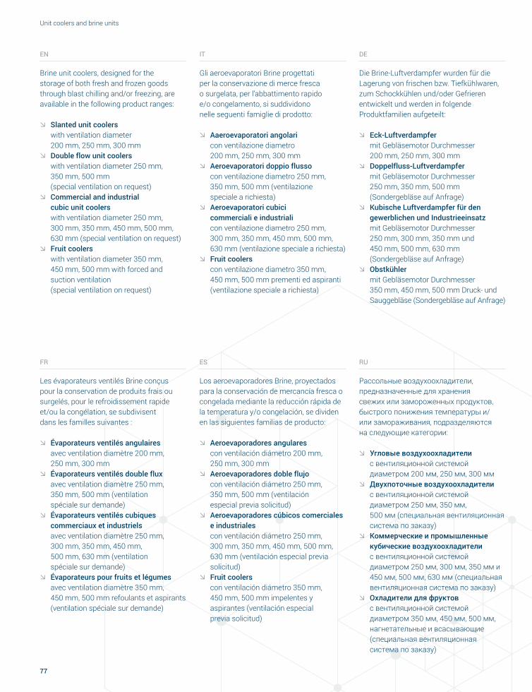
77
Unit coolers and brine units
EN
Brine unit coolers, designed for the storage of both fresh and frozen goods through blast chilling and/or freezing, are available in the following product ranges:
ØØ Slanted unit coolers with ventilation diameter 200 mm, 250 mm, 300 mmØØ Double flow unit coolers
with ventilation diameter 250 mm, 350 mm, 500 mm (special ventilation on request)ØØ Commercial and industrial
cubic unit coolers with ventilation diameter 250 mm, 300 mm, 350 mm, 450 mm, 500 mm, 630 mm (special ventilation on request)ØØ Fruit coolers
with ventilation diameter 350 mm, 450 mm, 500 mm with forced and suction ventilation (special ventilation on request)
FR
Les évaporateurs ventilés Brine conçus pour la conservation de produits frais ou surgelés, pour le refroidissement rapide et/ou la congélation, se subdivisent dans les familles suivantes :
ØØ Évaporateurs ventilés angulaires avec ventilation diamètre 200 mm, 250 mm, 300 mmØØ Évaporateurs ventilés double flux
avec ventilation diamètre 250 mm, 350 mm, 500 mm (ventilation spéciale sur demande)ØØ Évaporateurs ventilés cubiques
commerciaux et industriels avec ventilation diamètre 250 mm, 300 mm, 350 mm, 450 mm, 500 mm, 630 mm (ventilation spéciale sur demande)ØØ Évaporateurs pour fruits et légumes
avec ventilation diamètre 350 mm, 450 mm, 500 mm refoulants et aspirants (ventilation spéciale sur demande)
IT
Gli aeroevaporatori Brine progettati per la conservazione di merce fresca o surgelata, per l’abbattimento rapido e/o congelamento, si suddividono nelle seguenti famiglie di prodotto:
ØØ Aaeroevaporatori angolari con ventilazione diametro 200 mm, 250 mm, 300 mmØØ Aeroevaporatori doppio flusso
con ventilazione diametro 250 mm, 350 mm, 500 mm (ventilazione speciale a richiesta)ØØ Aeroevaporatori cubici
commerciali e industriali con ventilazione diametro 250 mm, 300 mm, 350 mm, 450 mm, 500 mm, 630 mm (ventilazione speciale a richiesta)ØØ Fruit coolers
con ventilazione diametro 350 mm, 450 mm, 500 mm prementi ed aspiranti (ventilazione speciale a richiesta)
ES
Los aeroevaporadores Brine, proyectados para la conservación de mercancía fresca o congelada mediante la reducción rápida de la temperatura y/o congelación, se dividen en las siguientes familias de producto:
ØØ Aeroevaporadores angulares con ventilación diámetro 200 mm, 250 mm, 300 mmØØ Aeroevaporadores doble flujo
con ventilación diámetro 250 mm, 350 mm, 500 mm (ventilación especial previa solicitud)ØØ Aeroevaporadores cúbicos comerciales
e industriales con ventilación diámetro 250 mm, 300 mm, 350 mm, 450 mm, 500 mm, 630 mm (ventilación especial previa solicitud)ØØ Fruit coolers
con ventilación diámetro 350 mm, 450 mm, 500 mm impelentes y aspirantes (ventilación especial previa solicitud)
DE
Die Brine-Luftverdampfer wurden für die Lagerung von frischen bzw. Tiefkühlwaren, zum Schockkühlen und/oder Gefrieren entwickelt und werden in folgende Produktfamilien aufgeteilt:
ØØ Eck-Luftverdampfer mit Gebläsemotor Durchmesser 200 mm, 250 mm, 300 mmØØ Doppelfluss-Luftverdampfer
mit Gebläsemotor Durchmesser 250 mm, 350 mm, 500 mm (Sondergebläse auf Anfrage)ØØ Kubische Luftverdampfer für den
gewerblichen und Industrieeinsatz mit Gebläsemotor Durchmesser 250 mm, 300 mm, 350 mm und 450 mm, 500 mm, 630 mm (Sondergebläse auf Anfrage)ØØ Obstkühler
mit Gebläsemotor Durchmesser 350 mm, 450 mm, 500 mm Druck- und Sauggebläse (Sondergebläse auf Anfrage)
RU
Рассольные воздухоохладители, предназначенные для хранения свежих или замороженных продуктов, быстрого понижения температуры и/или замораживания, подразделяются на следующие категории:
ØØ Угловые воздухоохладители с вентиляционной системой диаметром 200 мм, 250 мм, 300 ммØØ Двухпоточные воздухоохладители
с вентиляционной системой диаметром 250 мм, 350 мм, 500 мм (специальная вентиляционная система по заказу)ØØ Коммерческие и промышленные
кубические воздухоохладители с вентиляционной системой диаметром 250 мм, 300 мм, 350 мм и 450 мм, 500 мм, 630 мм (специальная вентиляционная система по заказу)ØØ Охладители для фруктов
с вентиляционной системой диаметром 350 мм, 450 мм, 500 мм, нагнетательные и всасывающие (специальная вентиляционная система по заказу)
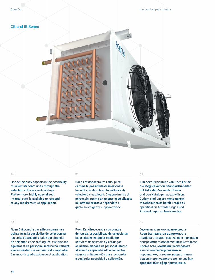
Roen Est Heat exchangers and more
78
IT
Roen Est annovera tra i suoi punti cardine la possibilità di selezionare le unità standard tramite software di selezione e cataloghi. Dispone inoltre di personale interno altamente specializzato nel settore pronto a rispondere a qualsiasi esigenza e applicazione.
ES
Roen Est ofrece, entre sus puntos de fuerza, la posibilidad de seleccionar las unidades estándar mediante software de selección y catálogos, asimismo dispone de personal interno altamente especializado en el sector, siempre a disposición para responder a cualquier necesidad y aplicación.
EN
One of their key aspects is the possibility to select standard units through the selection software and catalogs. Furthermore, highly specialized internal staff is available to respond to any requirement or application.
FR
Roen Est compte par ailleurs parmi ses points forts la possibilité de sélectionner les unités standard à l’aide d’un logiciel de sélection et de catalogues, elle dispose également de personnel interne hautement spécialisé dans le secteur prêt à répondre à n’importe quelle exigence et application.
DE
Einer der Pluspunkte von Roen Est ist die Möglichkeit die Standardeinheiten mit Hilfe der Auswahlsoftware und den Katalogen auszuwählen. Zudem sind unsere kompetenten Mitarbeiter stets bereit Fragen zu spezifischen Anforderungen und Anwendungen zu beantworten.
RU
Одним из главных преимуществ Roen Est является возможность подбора стандартных узлов с помощью программного обеспечения и каталогов. Кроме того, компания располагает высококвалифицированным персоналом, готовым предоставить решения для удовлетворения любых требований и сфер применения.
CB and IB Series

0 10 20 30 40 50 60 70
1.2 kW 15.6 kW
79
Unit coolers and brine units
CB.25
0 10 20 30 40 50 60 70
2.3 kW 26 kWCB.35
0 20 40 60 80 100 120 140 160 180 200
51 kW 180.3 kWIB.63
0
10.7 kW 81.8 kW
10 20 30 40 50 60 70 80 90
IB.50
0 10 20 30 40 50 60 70
5.1 kW 55.5 kWIB.45
KW DIAGRAM

Roen Est Heat exchangers and more
80
EN
ØØ The heat exchange coil is designed with geometries suited to different applications and temperatures, with a 9.52 mm (3/8’’) or 12 mm tube.
ØØ Fin spacing ranges between 3 mm and 12 mm, but differentiated fin spacings can be requested as well.
ØØ These options offer interesting technical solutions to customers, as well as an excellent €/kW ratio on all models.
ØØ In this regard, the Company can develop adequate circuit designs to guarantee medium-high outputs with the 12 mm tube as well, which would reduce the coil’s water/glycol charge enabling a broad range of applications at both high and low temperatures.
ØØ The quick selection software allows selecting the “recommended” fin spacing based on the desired cold room temperature, or to request specific fin spacings by entering values manually. The software also makes it possible to select compatible fluids such as water, glycol, ethylene glycol, and propylene glycol in different percentage concentrations, and – with the assistance of an internal technician – to request the thermodynamic sizing of units and verify the compatibility of all existing fluids on the market.
The fan coil is pressure tested at 18 bar, and each unit is inspected and monitored throughout the entire production process as per ISO 9001 standards.
IT
ØØ La batteria di scambio termico è realizzata con geometrie adatte alle varie applicazioni e temperature, con tubo da 9,52 mm (3/8’’), 12 mm.
ØØ I passi alette disponibili vanno da 3 mm a 12 mm con la possibilità di eseguire anche passi alette differenziati.
ØØ Queste possibilità permettono al mercato di ottenere interessanti soluzioni tecniche ed un rapporto €/kW altamente ottimizzato sui vari modelli.
ØØ A tal proposito si fa presente che l’azienda è in grado di sviluppare circuitazioni adeguate per garantire potenze medio-alte anche con il tubo da 12 mm, riducendo così le cariche di acqua/glicole sulla batteria permettendo un ampio range di applicazioni sia alle alte che alle basse temperature.
ØØ Il software di selezione rapido permette la scelta del passo alette “raccomandato” a seconda della temperatura cella desiderata, ovvero permette anche la scelta di specifici passi alette intervenendo manualmente. Il software permette inoltre la scelta dei fluidi compatibili come l’acqua, il glicole etilenico ed il glicole propilenico per diverse percentuali di concentrazione, nonché tramite i tecnici interni la possibilità di avere dimensionamenti termodinamici delle unità e verifica di compatibilità con tutti i fluidi disponibili sul mercato. Verifica di compatibilità con tutti i fluidi disponibili sul mercato.
La batteria viene collaudata in pressione a 18 bar ed ogni unità viene controllata e monitorata durante tutto il processo produttivo secondo le norme ISO 9001.
DE
ØØ Wärmetauschbatterien mit für die jeweiligen Anwendungen und Temperaturen geeigneten Geometrien, Rohrdurchmesser 9,52 mm (3/8''), 12 mm.
ØØ Lamellenabstand von 3 mm bis 12 mm, es können auch differenzierte Lamellenabstände verwirklicht werden.
ØØ Diese Möglichkeiten bieten dem Markt interessante technische Lösungen und ein optimales €/KW-Verhältnis für verschiedene Modelle.
ØØ Diesbezüglich wird darauf hingewiesen, dass die Firma in der Lage ist passende Rohrkreisläufe zu entwickeln, die auch bei Verwendung von 12 mm-Rohren mittelhohe Leistungen gewährleisten und somit die für den Wärmetauscher nötige Wasser-/Glykolmenge verringern und eine große Zahl von Anwendungsmöglichkeiten bei hohen und niedrigen Temperaturen ermöglichen. Die Auswahl-Software ermöglicht die Wahl des, je nach gewünschter Kühlraumtemperatur „empfohlenen“ Lamellenabstands bzw. ermöglicht auch die manuelle Wahl spezifischer Lamellenabstände.
ØØ Die Software ermöglicht zudem die Wahl der kompatiblen Kühlflüssigkeiten, wie Wasser, Ethylenglykol und Propylenglykol in verschiedener Konzentrierung sowie, mit Hilfe betriebsinterner Techniker, die Möglichkeit der thermodynamischen Dimensionierung der Einheiten und die Kompatibilitätsprüfung mit allen marktüblichen Kühlflüssigkeiten.
Der Wärmetauscher wird bei einem Druck von 18 Bar abgenommen. Jede Einheit wird während der gesamten Fertigungsphase nach ISO 9001 kontrolliert und überwacht.

81
Unit coolers and brine units
FR
ØØ La batterie d’échange thermique est réalisée avec des géométries adaptées aux différentes applications et températures, avec tube de 9,52 mm (3/8’’), 12 mm.
ØØ Les pas d’ailettes disponibles sont de 3 mm à 12 mm avec possibilité d’exécution avec des pas d’ailettes différents.
ØØ Ces possibilités permettent au marché d’obtenir des solutions techniques intéressantes et un rapport €/kW fortement optimisé sur les différents modèles.
ØØ À ce sujet, soulignons que l’Entreprise est en mesure de développer des circuits adéquats pour garantir des puissances moyennes-hautes même avec le tube de 12 mm, en réduisant ainsi les charges d’eau/glycol sur la batterie, en permettant une large plage d’applications aux hautes températures comme aux basses températures.
ØØ Le logiciel de sélection rapide permet de choisir le pas d’ailettes « recommandé » suivant la température désirée pour la chambre frigorifique, ou permet également de choisir des pas d’ailettes spécifiques en intervenant manuellement. Le logiciel permet également de choisir des fluides compatibles comme l’eau, l’éthylène glycol et le propylène glycol avec différents pourcentages de concentration, et par l’intermédiaire des techniciens internes, la possibilité d’avoir des dimensionnements thermodynamiques des unités et la vérification de la compatibilité avec tous les fluides disponibles sur le marché.
Le batterie est testée sous pression à 18 bars et chaque unité est contrôlée et suivie durant tout le processus de production conformément aux normes ISO 9001.
ES
ØØ La batería de intercambio térmico está realizada con geometrías aptas a diferentes aplicaciones y temperaturas, con tubo de 9,52 mm (3/8’’), 12 mm.
ØØ Los pasos de las aletas disponibles son de 3 mm a 12 mm con la posibilidad de realizar pasos de aletas diferenciados.
ØØ Estas posibilidades permiten obtener interesantes soluciones técnicas y una relación €/kW de gran optimización en los diferentes modelos.
ØØ A tal propósito se hace presente que la Empresa está en grado de desarrollar circuitos específicos para garantizar potencias medio-altas, incluso con tubos de 12 mm, reduciendo así las cargas de agua/glicol en la batería, lo que permite conseguir un amplio rango de aplicaciones, tanto a altas como a bajas temperaturas.
ØØ El software de selección rápida permite elegir el paso de las aletas “recomendado” dependiendo de la temperatura de cámara deseada, es decir, permite llevar a cabo la elección de determinados pasos de aletas mediante intervención manual. El software permite seleccionar los fluidos compatibles como el agua, el glicol etilénico y el glicol propilénico en diferentes porcentajes de concentración, así como nuestros técnicos pueden realizar las seleciones termodinámicas de las unidades y averiguar la compatibilidad con todos los fluidos disponibles en el mercado.
La batería se prueba a una presión de 18 bar y cada una de las unidades es sometida a control y monitorización durante todo el proceso productivo, de acuerdo con las normas ISO 9001.
RU
ØØ Теплообменная батарея имеет геометрии, подходящие для различных систем и температур, с трубой 9,52 мм (3/8’’), 12 мм.
ØØ Шаг ребер может составлять от 3 мм до 12 мм. Имеется возможность реализации дифференцированных шагов ребер.
ØØ Эти особенности позволяют создавать интересные технические решения и получать оптимизированное соотношение цены/мощности для различных моделей.
ØØ Следует отметить, что компания может разрабатывать соответствующие внутренние контуры для обеспечения средне-высокой мощности также с трубой 12 мм, сокращая таким образом содержание воды/гликоля в батарее и гарантируя широкий диапазон применения как при высоких, так и при низких температурах.
ØØ Программное обеспечение позволяет подбирать “рекомендованный” шаг ребер с учетом требуемой температуры холодильной камеры, а также особые шаги ребер в ручном режиме. С помощью программного обеспечения можно подбирать также совместимые жидкости, такие как вода, этиленгликоль и пропиленгликоль, для различных процентных концентраций.Технический персонал компании может оказать содействие в определении термодинамических размеров агрегатов и проверке совместимости со всеми жидкостями, имеющимися на рынке.
Батарея подвергается испытанию под давлением 18 бар, и каждое изделие проверяется и контролируется на протяжении всего процесса производства в соответствии с нормами ISO 9001.
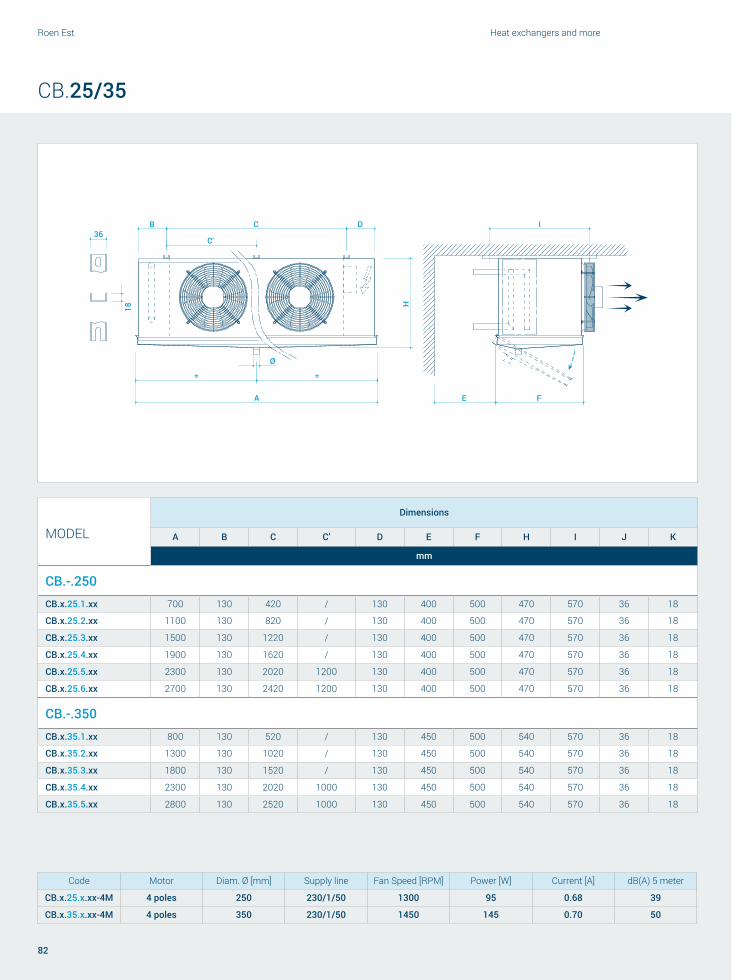
A
B C D
HE F
I
= =
18
36
Ø
C'
Roen Est Heat exchangers and more
82
CB.25/35
MODEL
Dimensions
A B C C’ D E F H I J K
mm
CB.-.250CB.x.25.1.xx 700 130 420 / 130 400 500 470 570 36 18
CB.x.25.2.xx 1100 130 820 / 130 400 500 470 570 36 18
CB.x.25.3.xx 1500 130 1220 / 130 400 500 470 570 36 18
CB.x.25.4.xx 1900 130 1620 / 130 400 500 470 570 36 18
CB.x.25.5.xx 2300 130 2020 1200 130 400 500 470 570 36 18
CB.x.25.6.xx 2700 130 2420 1200 130 400 500 470 570 36 18
CB.-.350CB.x.35.1.xx 800 130 520 / 130 450 500 540 570 36 18
CB.x.35.2.xx 1300 130 1020 / 130 450 500 540 570 36 18
CB.x.35.3.xx 1800 130 1520 / 130 450 500 540 570 36 18
CB.x.35.4.xx 2300 130 2020 1000 130 450 500 540 570 36 18
CB.x.35.5.xx 2800 130 2520 1000 130 450 500 540 570 36 18
Code Motor Diam. Ø [mm] Supply line Fan Speed [RPM] Power [W] Current [A] dB(A) 5 meter
CB.x.25.x.xx-4M 4 poles 250 230/1/50 1300 95 0.68 39
CB.x.35.x.xx-4M 4 poles 350 230/1/50 1450 145 0.70 50
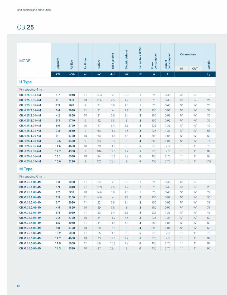
83
Unit coolers and brine units
CB.25
MODELCa
paci
ty
Air fl
ow
Air t
hrow
Surf
ace
Tube
vol
ume
Elec
tric
def
rost
Fan
mot
ors
Ø 2
50
Pow
er
cons
umpt
ion
Curr
ent
cons
umpt
ion Connections
Wei
ght
IN OUT
kW m3/h m m2 dm3 kW N° W A kg
H Type
Fin spacing 4 mm
CB.H.25.1.04-4M 1.7 1040 11 10.4 2 0.9 1 75 0.46 ½” ½” 19
CB.H.25.1.06-4M 2.1 930 10 15.6 2.5 1.2 1 75 0.46 ½” ½” 21
CB.H.25.1.08-4M 2.3 870 9 21 3.9 1.5 1 75 0.46 ¾” ¾” 23
CB.H.25.2.04-4M 3.4 2080 11 21 4 1.8 2 150 0.92 ¾” ¾” 32
CB.H.25.2.06-4M 4.2 1860 10 31 5.9 2.4 2 150 0.92 ¾” ¾” 35
CB.H.25.2.08-4M 5.3 1740 9 42 7.8 3 2 150 0.92 ¾” ¾” 39
CB.H.25.3.06-4M 6.6 2790 10 47 8.4 3.6 3 225 1.38 ¾” ¾” 49
CB.H.25.3.08-4M 7.8 2610 9 63 11.7 4.5 3 225 1.38 ¾” ¾” 56
CB.H.25.4.06-4M 9.1 3720 10 63 11.8 4.8 4 300 1.84 ¾” ¾” 62
CB.H.25.4.08-4M 10.5 3480 9 83 15.6 6 4 300 1.84 ¾” ¾” 71
CB.H.25.5.06-4M 11.6 4650 10 78 14.3 5.8 5 375 2.3 1” 1” 75
CB.H.25.5.08-4M 12.7 4350 9 104 19.5 7.2 5 375 2.3 1” 1” 89
CB.H.25.6.06-4M 13.1 5580 10 94 16.8 7.2 6 450 2.76 1” 1” 90
CB.H.25.6.08-4M 15.6 5220 9 125 23.4 9 6 450 2.76 1” 1” 103
M Type
Fin spacing 6 mm
CB.M.25.1.04-4M 1.3 1080 11 7.3 2 0.9 1 75 0.46 ½” ½” 18
CB.M.25.1.06-4M 1.9 1010 11 10.9 2.5 1.2 1 75 0.46 ½” ½” 20
CB.M.25.1.08-4M 2.2 980 10 14.6 3.9 1.5 1 75 0.46 ¾” ¾” 22
CB.M.25.2.04-4M 2.9 2160 11 14.6 4 1.8 2 150 0.92 ¾” ¾” 30
CB.M.25.2.06-4M 3.7 2020 11 22 5.9 2.4 2 150 0.92 ¾” ¾” 33
CB.M.25.2.08-4M 4.5 1860 10 29 7.8 3 2 150 0.92 ¾” ¾” 37
CB.M.25.3.06-4M 6.4 3030 11 33 8.4 3.6 3 225 1.38 ¾” ¾” 46
CB.M.25.3.08-4M 7.2 2790 10 44 11.7 4.5 3 225 1.38 ¾” ¾” 52
CB.M.25.4.06-4M 8.5 4040 11 44 11.8 4.8 4 300 1.84 ¾” ¾” 58
CB.M.25.4.08-4M 9.8 3720 10 58 15.6 6 4 300 1.84 ¾” ¾” 66
CB.M.25.5.06-4M 10.2 5050 11 55 14.3 5.8 5 375 2.3 1” 1” 70
CB.M.25.5.08-4M 11.7 4650 10 73 19.5 7.2 5 375 2.3 1” 1” 82
CB.M.25.6.06-4M 11.9 6060 11 66 16.8 7.2 6 450 2.76 1” 1” 84
CB.M.25.6.08-4M 14.3 5580 10 87 23.4 9 6 450 2.76 1” 1” 96

Roen Est Heat exchangers and more
84
MODEL
Capa
city
Air fl
ow
Air t
hrow
Surf
ace
Tube
vol
ume
Elec
tric
def
rost
Fan
mot
ors
Ø 2
50
Pow
er
cons
umpt
ion
Curr
ent
cons
umpt
ion Connections
Wei
ght
IN OUT
kW m3/h m m2 dm3 kW N° W A kg
L Type
Fin spacing 8 mm
CB.L.25.1.04-4M 1.2 1120 12 5.7 2 0.9 1 75 0.46 ½” ½” 17
CB.L.25.1.06-4M 1.8 1020 11 8.6 2.5 1.2 1 75 0.46 ½” ½” 19
CB.L.25.1.08-4M 2.1 930 10 11.5 3.9 1.5 1 75 0.46 ¾” ¾” 21
CB.L.25.2.04-4M 2.5 2240 12 11.5 4 1.8 2 150 0.92 ¾” ¾” 28
CB.L.25.2.06-4M 3.5 2040 11 17.2 5.9 2.4 2 150 0.92 ¾” ¾” 31
CB.L.25.2.08-4M 3.8 1960 10 23 7.8 3 2 150 0.92 ¾” ¾” 34
CB.L.25.3.06-4M 5.4 3060 11 26 8.4 3.6 3 225 1.38 ¾” ¾” 43
CB.L.25.3.08-4M 6.3 2940 10 34 11.7 4.5 3 225 1.38 ¾” ¾” 48
CB.L.25.4.06-4M 7.2 4080 11 34 11.8 4.8 4 300 1.84 ¾” ¾” 54
CB.L.25.4.08-4M 8.7 3920 10 46 15.6 6 4 300 1.84 ¾” ¾” 60
CB.L.25.5.06-4M 9 5100 11 43 14.3 5.8 5 375 2.3 1” 1” 65
CB.L.25.5.08-4M 10.5 4900 10 57 19.5 7.2 5 375 2.3 1” 1” 75
CB.L.25.6.06-4M 10.7 6120 11 52 16.8 7.2 6 450 2.76 1” 1” 78
CB.L.25.6.08-4M 12.7 5880 10 69 23.4 9 6 450 2.76 1” 1” 88
CB.25

85
Unit coolers and brine units
MODELCa
paci
ty
Air fl
ow
Air t
hrow
Surf
ace
Tube
vol
ume
Elec
tric
def
rost
Fan
mot
ors
Ø 3
50
Pow
er
cons
umpt
ion
Curr
ent
cons
umpt
ion Connections
Wei
ght
IN OUT
kW m3/h m m2 dm3 kW N° W A kg
H Type
Fin spacing 4 mm
CB.H.35.1.04-4M 3.2 2450 17 15.9 2.9 1.2 1 180 0.7 ¾” ¾” 26
CB.H.35.1.06-4M 4 2210 15 24 4.3 2 1 180 0.7 ¾” ¾” 30
CB.H.35.1.08-4M 4.6 2000 14 32 5.8 2.4 1 180 0.7 ¾” ¾” 34
CB.H.35.2.04-4M 7 4900 17 32 5.8 2.2 2 360 1.4 ¾” ¾” 43
CB.H.35.2.06-4M 9.3 4420 15 48 8.7 3.8 2 360 1.4 ¾” ¾” 51
CB.H.35.2.08-4M 10.6 4000 14 64 11.6 4.5 2 360 1.4 ¾” ¾” 59
CB.H.35.3.06-4M 13.9 6630 15 72 13 5.6 3 540 2.1 1” 1” 74
CB.H.35.3.08-4M 15.3 6000 14 96 17.4 6.7 3 540 2.1 1” 1” 86
CB.H.35.4.06-4M 18 8840 15 96 17.4 7.5 4 720 2.8 1” 1” 96
CB.H.35.4.08-4M 21.1 8000 14 128 23.2 9 4 720 2.8 1” ¼ 1” ¼ 113
CB.H.35.5.06-4M 22 11050 15 120 22 9.5 5 900 3.5 1” ¼ 1” ¼ 118
CB.H.35.5.08-4M 26.9 10000 14 159 29 11.4 5 900 3.5 1” ¼ 1” ¼ 137
M Type
Fin spacing 6 mm
CB.M.35.1.04-4M 2.7 2580 18 11.2 2.9 1.2 1 180 0.7 ¾” ¾” 25
CB.M.35.1.06-4M 3.7 2320 16 16.8 4.3 2 1 180 0.7 ¾” ¾” 29
CB.M.35.1.08-4M 4.4 2170 15 22 5.8 2.4 1 180 0.7 ¾” ¾” 32
CB.M.35.2.04-4M 5.4 5160 18 22 5.8 2.2 2 360 1.4 ¾” ¾” 41
CB.M.35.2.06-4M 7.5 4640 16 33 8.7 3.8 2 360 1.4 ¾” ¾” 48
CB.M.35.2.08-4M 9 4340 15 45 11.6 4.5 2 360 1.4 ¾” ¾” 55
CB.M.35.3.06-4M 11.2 6960 16 50 13 5.6 3 540 2.1 1” 1” 69
CB.M.35.3.08-4M 14 6510 15 67 17.4 6.7 3 540 2.1 1” 1” 79
CB.M.35.4.06-4M 15 9280 16 67 17.4 7.5 4 720 2.8 1” 1” 89
CB.M.35.4.08-4M 19 8680 15 89 23.2 9 4 720 2.8 1” ¼ 1” ¼ 104
CB.M.35.5.06-4M 19.8 11600 16 84 22 9.5 5 900 3.5 1” ¼ 1” ¼ 110
CB.M.35.5.08-4M 23 10850 15 112 29 11.4 5 900 3.5 1” ¼ 1” ¼ 127
CB.35

Roen Est Heat exchangers and more
86
MODEL
Capa
city
Air fl
ow
Air t
hrow
Surf
ace
Tube
vol
ume
Elec
tric
def
rost
Fan
mot
ors
Ø 3
50
Pow
er
cons
umpt
ion
Curr
ent
cons
umpt
ion Connections
Wei
ght
IN OUT
kW m3/h m m2 dm3 kW N° W A kg
L Type
Fin spacing 8 mm
CB.L.35.1.04-4M 2.3 2630 18 8.8 2.9 1.2 1 180 0.7 ¾” ¾” 24
CB.L.35.1.06-4M 3.2 2430 17 13.2 4.3 2 1 180 0.7 ¾” ¾” 27
CB.L.35.1.08-4M 3.8 2220 15 17.8 5.8 2.4 1 180 0.7 ¾” ¾” 30
CB.L.35.2.04-4M 4.8 5260 18 17.5 5.8 2.2 2 360 1.4 ¾” ¾” 39
CB.L.35.2.06-4M 6.7 4860 17 26 8.7 3.8 2 360 1.4 ¾” ¾” 45
CB.L.35.2.08-4M 8 4440 15 35 11.6 4.5 2 360 1.4 ¾” ¾” 51
CB.L.35.3.06-4M 10.5 7290 17 39 13 5.6 3 540 2.1 1” 1” 64
CB.L.35.3.08-4M 12 6660 15 53 17.4 6.7 3 540 2.1 1” 1” 73
CB.L.35.4.06-4M 13.7 9720 17 53 17.4 7.5 4 720 2.8 1” 1” 83
CB.L.35.4.08-4M 16.2 8880 15 70 23.2 9 4 720 2.8 1” ¼ 1” ¼ 95
CB.L.35.5.06-4M 16.9 12150 17 66 22 9.5 5 900 3.5 1” ¼ 1” ¼ 102
CB.L.35.5.08-4M 20.5 11100 15 88 29 11.4 5 900 3.5 1” ¼ 1” ¼ 116
CB.35

A
H
B C D
= =
76
40
Ø
C'
I
E F
87
Unit coolers and brine units
IB.45/50/63
MODEL
Dimensions
A B C C’ D E F H I J K Ø
mm
IB.-.45IB.x.45.1.xx 1075 155 755 / 155 600 550 740 660 76 40 2”
IB.x.45.2.xx 1800 155 1480 / 155 600 550 740 660 76 40 2”
IB.x.45.3.xx 2525 155 2205 1450 155 600 550 740 660 76 40 2”
IB.x.45.4.xx 3250 155 2930 1450 155 600 550 740 660 76 40 2”
IB.x.45.5.xx 3975 155 3655 1450 155 600 550 740 660 76 40 2”
IB.-.50IB.x.50.1.xx 1250 155 930 / 155 800 690 810 800 76 40 2”
IB.x.50.2.xx 2150 155 1830 / 155 800 690 810 800 76 40 2”
IB.x.50.3.xx 3050 155 2730 1800 155 800 690 810 800 76 40 3”
IB.x.50.4.xx 3950 155 3630 1800 155 800 690 810 800 76 40 3”
IB.-.63IB.x.63.2.xx 2550 155 2230 / 155 1000 810 1250 920 76 40 3”
IB.x.63.3.xx 3650 155 3330 2200 155 1000 810 1250 920 76 40 3”
IB.x.63.4.xx 4750 155 4430 2200 155 1000 810 1250 920 76 40 3”
Code Motor Diam. Ø [mm] Supply line
Δ Y
Speed [RPM] Power [W] Current [A] dB (A) 5 m Speed [RPM] Power [W] Current [A] dB (A) 5 m
IB.x.45.x.xx-4T 4 poles 450 400/3/50 1400 590 0.9 50 1180 305 0.55 44
IB.x.50.x.xx-4T 4 poles 500 400/3/50 1340 780 1.35 51 1000 550 0.94 44
IB.x.63.x.xx-4T 4 poles 630 400/3/50 1310 2600 4.8 63 1000 1600 2.7 57

Roen Est Heat exchangers and more
88
IB.45
MODEL
Capa
city
Air fl
ow
Air t
hrow
Surf
ace
Tube
vol
ume
Elec
tric
def
rost
Fan
mot
ors
Ø 4
50
Pow
er
cons
umpt
ion
Curr
ent
cons
umpt
ion Connections
Wei
ght
IN OUT
kW m3/h m m2 dm3 kW N° W A kg
H Type
Fin spacing 4 mm
IB.H.45.1.04-4T 7.6 5400 28 32 5.9 2.7 1 590 0.9 ¾” ¾” 54
IB.H.45.1.06-4T 9 5000 26 48 8.8 3.8 1 590 0.9 ¾” ¾” 61
IB.H.45.1.08-4T 10.9 4600 24 63 12 4.9 1 590 0.9 1” 1” 69
IB.H.45.2.04-4T 13.8 10800 28 63 11.8 5.5 2 1180 1.8 1” 1” 90
IB.H.45.2.06-4T 19.3 9900 26 95 17.6 87.7 2 1180 1.8 1” 1” 107
IB.H.45.2.08-4T 22.9 9200 24 126 24 9.9 2 1180 1.8 1” ¼ 1” ¼ 122
IB.H.45.3.06-4T 28.4 14900 26 143 26 11.2 3 1770 2.7 1” ¼ 1” ¼ 148
IB.H.45.3.08-4T 33.8 13800 24 189 36 14.4 3 1770 2.7 1” ½ 1” ½ 170
IB.H.45.4.06-4T 39.9 19800 26 190 36 14.7 4 2360 3.6 1” ½ 1” ½ 191
IB.H.45.4.08-4T 45.7 18400 24 252 48 18.9 4 2360 3.6 1” ½ 1” ½ 221
IB.H.45.5.08-4T 55.5 23000 24 351 60 23.4 5 2950 4.5 2” 2” 272
M Type
Fin spacing 6 mm
IB.M.45.1.04-4T 5.9 5600 29 22 5.9 2.7 1 590 0.9 ¾” ¾” 52
IB.M.45.1.06-4T 8.3 5200 27 34 8.8 3.8 1 590 0.9 ¾” ¾” 58
IB.M.45.1.08-4T 9.9 4800 25 45 12 4.9 1 590 0.9 1” 1” 65
IB.M.45.2.04-4T 11.7 11100 29 44 11.8 5.5 2 1180 1.8 1” 1” 86
IB.M.45.2.06-4T 16.5 10300 27 67 17.6 87.7 2 1180 1.8 1” 1” 100
IB.M.45.2.08-4T 19.8 9600 25 89 24 9.9 2 1180 1.8 1” ¼ 1” ¼ 113
IB.M.45.3.06-4T 24.8 15500 27 101 26 11.2 3 1770 2.7 1” ¼ 1” ¼ 139
IB.M.45.3.08-4T 29.7 14400 25 134 36 14.4 3 1770 2.7 1” ½ 1” ½ 158
IB.M.45.4.06-4T 32.9 20600 27 134 36 14.7 4 2360 3.6 1” ½ 1” ½ 179
IB.M.45.4.08-4T 39.6 19200 25 178 48 18.9 4 2360 3.6 1” ½ 1” ½ 204
IB.M.45.5.08-4T 49.5 24000 25 222 60 23.4 5 2950 4.5 2” 2” 251

89
Unit coolers and brine units
IB.45
MODELCa
paci
ty
Air fl
ow
Air t
hrow
Surf
ace
Tube
vol
ume
Elec
tric
def
rost
Fan
mot
ors
Ø 4
50
Pow
er
cons
umpt
ion
Curr
ent
cons
umpt
ion Connections
Wei
ght
IN OUT
kW m3/h m m2 dm3 kW N° W A kg
L Type
Fin spacing 8 mm
IB.L.45.1.04-4T 5.1 5700 30 18 5.9 2.7 1 590 0.9 ¾” ¾” 50
IB.L.45.1.06-4T 6.9 5300 28 27 8.8 3.8 1 590 0.9 ¾” ¾” 55
IB.L.45.1.08-4T 8.5 5000 26 36 12 4.9 1 590 0.9 1” 1” 61
IB.L.45.2.04-4T 10.7 11400 30 35 11.8 5.5 2 1180 1.8 1” 1” 82
IB.L.45.2.06-4T 14.7 10500 28 53 17.6 87.7 2 1180 1.8 1” 1” 94
IB.L.45.2.08-4T 17.9 9900 26 71 24 9.9 2 1180 1.8 1” ¼ 1” ¼ 105
IB.L.45.3.06-4T 21.7 15800 28 80 26 11.2 3 1770 2.7 1” ¼ 1” ¼ 129
IB.L.45.3.08-4T 26.5 14900 26 107 36 14.4 3 1770 2.7 1” ½ 1” ½ 145
IB.L.45.4.06-4T 28.5 21000 28 107 36 14.7 4 2360 3.6 1” ½ 1” ½ 166
IB.L.45.4.08-4T 36.3 19800 26 142 48 18.9 4 2360 3.6 1” ½ 1” ½ 187
IB.L.45.5.08-4T 44.2 24700 26 177 60 23.4 5 2950 4.5 2” 2” 230

Roen Est Heat exchangers and more
90
IB.50
MODEL
Capa
city
Air fl
ow
Air t
hrow
Surf
ace
Tube
vol
ume
Elec
tric
def
rost
Fan
mot
ors
Ø 5
00
Pow
er
cons
umpt
ion
Curr
ent
cons
umpt
ion Connections
Wei
ght
IN OUT
kW m3/h m m2 dm3 kW N° W A kg
H Type
Fin spacing 4 mm
IB.H.50.1.06-4T 13.3 7600 37 67 12 5.6 1 780 1.4 1” 1” 75
IB.H.50.1.08-4T 16.6 7000 35 89 16 7.2 1 780 1.4 1” 1” 86
IB.H.50.1.12-4T 20 6200 31 133 24 11 1 780 1.4 1” ¼ 1” ¼ 107
IB.H.50.2.06-4T 28.1 15200 37 133 24 10.5 2 1560 2.8 1” ¼ 1” ¼ 134
IB.H.50.2.08-4T 33.1 14000 35 178 32 13.5 2 1560 2.8 1” ¼ 1” ¼ 155
IB.H.50.2.12-4T 40.9 12400 31 267 48 21 2 1560 2.8 1” ½ 1” ½ 196
IB.H.50.3.08-4T 48.5 21000 35 267 48 20.7 3 2340 4.2 1” ½ 1” ½ 224
IB.H.50.3.12-4T 60.2 18600 31 400 72 32.2 3 2340 4.2 2” 2” 284
IB.H.50.4.08-4T 67.5 28000 35 356 64 27.4 4 3120 5.6 2” 2” 293
IB.H.50.4.12-4T 81.8 24800 31 533 96 42.7 4 3120 5.6 2” ½ 2” ½ 373
M Type
Fin spacing 6 mm
IB.M.50.1.06-4T 11.7 7900 39 47 12 5.6 1 780 1.4 1” 1” 70
IB.M.50.1.08-4T 14.7 7400 37 62 16 7.2 1 780 1.4 1” 1” 80
IB.M.50.1.12-4T 17.6 6600 33 93 24 11 1 780 1.4 1” ¼ 1” ¼ 98
IB.M.50.2.06-4T 23.4 15800 39 93 24 10.5 2 1560 2.8 1” ¼ 1” ¼ 125
IB.M.50.2.08-4T 28.4 14800 37 125 32 13.5 2 1560 2.8 1” ¼ 1” ¼ 143
IB.M.50.2.12-4T 36 13200 33 187 48 21 2 1560 2.8 1” ½ 1” ½ 178
IB.M.50.3.08-4T 43.2 22200 37 187 48 20.7 3 2340 4.2 1” ½ 1” ½ 207
IB.M.50.3.12-4T 54.5 19800 33 280 72 32.2 3 2340 4.2 2” 2” 258
IB.M.50.4.08-4T 58.9 29600 37 249 64 27.4 4 3120 5.6 2” 2” 270
IB.M.50.4.12-4T 72.1 26400 33 373 96 42.7 4 3120 5.6 2” ½ 2” ½ 338

91
Unit coolers and brine units
IB.50
MODELCa
paci
ty
Air fl
ow
Air t
hrow
Surf
ace
Tube
vol
ume
Elec
tric
def
rost
Fan
mot
ors
Ø 5
00
Pow
er
cons
umpt
ion
Curr
ent
cons
umpt
ion Connections
Wei
ght
IN OUT
kW m3/h m m2 dm3 kW N° W A kg
L Type
Fin spacing 8 mm
IB.L.50.1.06-4T 10.7 8000 40 37 12 5.6 1 780 1.4 1” 1” 66
IB.L.50.1.08-4T 12.1 7200 37 49 16 7.2 1 780 1.4 1” 1” 74
IB.L.50.1.12-4T 16.3 6800 34 74 24 11 1 780 1.4 1” ¼ 1” ¼ 89
IB.L.50.2.06-4T 21.4 16000 40 74 24 10.5 2 1560 2.8 1” ¼ 1” ¼ 116
IB.L.50.2.08-4T 26.1 15200 37 98 32 13.5 2 1560 2.8 1” ¼ 1” ¼ 131
IB.L.50.2.12-4T 31.8 13600 34 147 48 21 2 1560 2.8 1” ½ 1” ½ 160
IB.L.50.3.08-4T 39.6 22800 37 147 48 20.7 3 2340 4.2 1” ½ 1” ½ 189
IB.L.50.3.12-4T 50.4 20400 34 221 72 32.2 3 2340 4.2 2” 2” 231
IB.L.50.4.08-4T 54.8 32000 37 196 64 27.4 4 3120 5.6 2” 2” 246
IB.L.50.4.12-4T 69.2 30400 34 294 96 42.7 4 3120 5.6 2” ½ 2” ½ 302

Roen Est Heat exchangers and more
92
IB.63
MODEL
Capa
city
Air fl
ow
Air t
hrow
Surf
ace
Tube
vol
ume
Elec
tric
def
rost
Fan
mot
ors
Ø 6
30
Pow
er
cons
umpt
ion
Curr
ent
cons
umpt
ion Connections
Wei
ght
IN OUT
kW m3/h m m2 dm3 kW N° W A kg
H Type
Fin spacing 4 mm
IB.H.63.2.08-4T 73.9 32600 55 350 65 32.4 2 4400 8.6 2” 2” 310
IB.H.63.2.10-4T 81.1 30800 52 437 80 37.8 2 4400 8.6 2” 2” 352
IB.H.63.2.12-4T 89.5 29400 50 525 97 48.6 2 4400 8.6 2” ½ 2” ½ 392
IB.H.63.3.08-4T 106.8 48900 55 525 98 45 3 6600 12.9 2” ½ 2” ½ 453
IB.H.63.3.10-4T 126.5 46200 52 655 120 52.5 3 6600 12.9 2” ½ 2” ½ 514
IB.H.63.3.12-4T 133.8 44100 50 787 145 67.5 3 6600 12.9 3” 3” 572
IB.H.63.4.08-4T 147.9 65200 55 700 130 61.2 4 8800 17.2 2” ½ 2” ½ 597
IB.H.63.4.10-4T 167.7 61600 52 874 160 71.4 4 8800 17.2 3” 3” 682
IB.H.63.4.12-4T 180.3 58800 50 1050 194 91.8 4 8800 17.2 3” 3” 755
M Type
Fin spacing 6 mm
IB.M.63.2.08-4T 60.8 34200 58 247 65 32.4 2 4400 8.6 2” 2” 288
IB.M.63.2.10-4T 68.4 32600 55 309 80 37.8 2 4400 8.6 2” 2” 325
IB.M.63.2.12-4T 80.5 31200 53 371 97 48.6 2 4400 8.6 2” ½ 2” ½ 360
IB.M.63.3.08-4T 96.9 51300 58 371 98 45 3 6600 12.9 2” ½ 2” ½ 420
IB.M.63.3.10-4T 109.7 48900 55 463 120 52.5 3 6600 12.9 2” ½ 2” ½ 473
IB.M.63.3.12-4T 116.3 46800 53 578 145 67.5 3 6600 12.9 3” 3” 524
IB.M.63.4.08-4T 121.6 68400 58 494 130 61.2 4 8800 17.2 2” ½ 2” ½ 553
IB.M.63.4.10-4T 142.9 65200 55 618 160 71.4 4 8800 17.2 3” 3” 623
IB.M.63.4.12-4T 157.4 62400 53 742 194 91.8 4 8800 17.2 3” 3” 691

93
Unit coolers and brine units
IB.63
MODELCa
paci
ty
Air fl
ow
Air t
hrow
Surf
ace
Tube
vol
ume
Elec
tric
def
rost
Fan
mot
ors
Ø 6
30
Pow
er
cons
umpt
ion
Curr
ent
cons
umpt
ion Connections
Wei
ght
IN OUT
kW m3/h m m2 dm3 kW N° W A kg
L Type
Fin spacing 8 mm
IB.L.63.2.08-4T 51 35000 59 196 65 32.4 2 4400 8.6 2” 2” 262
IB.L.63.2.10-4T 65 33200 56 245 80 37.8 2 4400 8.6 2” 2” 294
IB.L.63.2.12-4T 70.5 31900 54 294 97 48.6 2 4400 8.6 2” ½ 2” ½ 326
IB.L.63.3.08-4T 85.5 52500 59 294 98 45 3 6600 12.9 2” ½ 2” ½ 381
IB.L.63.3.10-4T 92.6 49800 56 367 120 52.5 3 6600 12.9 2” ½ 2” ½ 426
IB.L.63.3.12-4T 108.3 47900 54 441 145 67.5 3 6600 12.9 3” 3” 473
IB.L.63.4.08-4T 114.5 70000 59 392 130 61.2 4 8800 17.2 2” ½ 2” ½ 501
IB.L.63.4.10-4T 130.1 66400 56 490 160 71.4 4 8800 17.2 3” 3” 560
IB.L.63.4.12-4T 141.7 63800 54 588 194 91.8 4 8800 17.2 3” 3” 623

3
6
2
4
5
7
1
Roen Est Heat exchangers and more
94
ACCESSORIESIncreased electric defrost (+25%)
¬ Sbrinamento elettrico potenziato (+25%) ¬ Verbesserte elektrische Abtauung (+25%) ¬ Dégivrage électrique renforcé (+25 %) ¬ Desescarche eléctrico potenciado (+25%) ¬ Улучшенное электрическое оттаивание (+25%)
Prepainted fins
¬ Предварительно окрашенные ребра ¬ Aletas prepintadas ¬ Ailettes prélaquées ¬ Vorlackierte Lamellen ¬ Alette preverniciate
AISI 304 - 316L frames
Grids electric defrost
Units with reheat
Surface treatments
Water defrost
¬ Trattamenti superficiali ¬ Verschiedenen Schutzbeschichtungen ¬ Traitements de surface ¬ Tratamientos superficiales ¬ Поверхностные покрытияx
¬ Unità con post riscaldamento ¬ Einheit mit Nacherhitzer ¬ Unité avec post-chauffage ¬ Unidad con post calentamiento ¬ Агрегаты с постнагревом
¬ Sbrinamento ad acqua ¬ Wasserabtauung ¬ Dégivrage à l’eau ¬ Desescarche con agua ¬ Оттаивание водой
¬ Электрическое оттаивание решеток ¬ Desescarche eléctrico rejillas ¬ Dégivrage électrique grilles ¬ Elektrische Abtauung der Gitter ¬ Sbrinamento elettrico griglie
¬ Рама AISI 304 - 316L ¬ Bastidores en AISI 304 - 316L ¬ Cadre en acier AISI 304 - 316L ¬ Gestell: AISI 304 - 316L ¬ Telaio in AISI 304 - 316L

13
10
12
11
8
9
95
Unit coolers and brine units
AISI 304 - 316 tubes
¬ Трубы AISI 304 - 316 ¬ Tubos AISI 304 - 316 ¬ Tubes en acier AISI 304 - 316 ¬ Rohre: AISI 304 - 316 ¬ Tubi AISI 304 - 316
Hot glycol defrost
Insulated tray
Motor wiring
Hot gas defrost
EC / ATEX motors
¬ Motori EC / Motori ATEX ¬ EC-Motoren / ATEX-Motoren ¬ Moteurs EC / Moteurs ATEX ¬ Motores EC / Motores ATEX ¬ Двигатели EC / Двигатели ATEX
Accessori Zubehör Accessoires Accesorios Аксессуары
¬ Cablaggio motori ¬ Motorverdrahtung ¬ Câblage moteurs ¬ Cableado motores ¬ Кабельная проводка двигателей
¬ Sbrinamento hot gas ¬ Heißgasabtauung ¬ Dégivrage par gaz chaud ¬ Desescarche hot gas ¬ Оттаивание горячим газом
¬ Изолированный поддон ¬ Bandeja aislada ¬ Bac isolé ¬ Isolierte Wanne ¬ Vaschetta isolata
¬ Оттаивание горячим гликолем ¬ Desescarche con glicol caliente ¬ Dégivrage au glycol chaud ¬ Abtausystem mit Warmglykol ¬ Sbrinamento con glicole caldo

Roen Est Heat exchangers and more
96
97
Unit coolers and brine units

Roen Est Heat exchangers and more
98
EN
ØØ View and print in PDF formatØØ Save your selectionsØØ Broad range of configuration optionsØØ High reliability
ES
ØØ Visualización e impresión en formato PDFØØ Memorización de las
propias seleccionesØØ Amplias configuraciones posiblesØØ Gran fiabilidad
RU
ØØ Отображение и печать в формате PDFØØ Сохранение собственного выбораØØ Большое разнообразие конфигурацийØØ Высокая надежность
IT
ØØ Visualizzazione e stampa in formato PDFØØ Memorizzazione delle proprie selezioniØØ Ampie configurazioni possibiliØØ Grande affidabilità
DE
ØØ Darstellung und Ausdruck im PDF-FormatØØ Einspeicherung der vorgenommenen
AuswahlØØ Zahlreiche KonfigurationsmöglichkeitenØØ Hohe Zuverlässigkeit
FR
ØØ Affichage et impression au format PDFØØ Mémorisation des sélections
personnellesØØ Nombreuses configurations possiblesØØ Grande fiabilité
SOFTWARE: REVENT

99
Unit coolers and brine units
EN
Calculations made quick and easyOur REvent selection program makes it simple to select unit coolers, remote condensers, brine coolers, and dry coolers. It also offers the possibility to calculate the cold room.
The selection software can be downloaded from our website, and activated via password supplied on request by our technical/commercial office.
FR
L’instrument le plus facile et le plus rapide pour le calculAvec notre programme de sélection REvent vous pouvez sélectionner facilement les évaporateurs ventilés, les condenseurs à distance, les refroidisseurs de saumure et les aéroréfrigérants secs. Le logiciel offre également la possibilité de calculer la chambre frigorifique.
Il peut être téléchargé à partir de notre site internet et pourra être activé avec mot de passe fourni sur demande par notre service technique/commercial.
IT
Lo strumento più facile e veloce per il calcoloCon il nostro programma di selezione REvent potete facilmente selezionare aeroevaporatori, condensatori remoti, brine coolers e dry coolers. Il software offre anche la possibilità di calcolare la cella frigorifera.
Esso è scaricabile dal nostro sito internet e potrà essere attivato con password fornita a richiesta dal nostro ufficio tecnico/commerciale.
ES
El instrumento más fácil y rápido para el cálculoCon nuestro programa de selección REvent podrá seleccionar fácilmente aeroevaporadores, condensadores remotos, brine coolers y dry coolers. Asimismo, el software ofrece la posibilidad de calcular la celda frigorífera.
Dicho programa puede ser descargado desde nuestro sitio Internet con activación mediante contraseña, previa solicitud, facilitada por nuestro departamento técnico/comercial.
DE
Das einfachste und schnellste BerechnungtoolMit unserer Auswahlsoftware REvent können Sie in einfachster Weise Luftverdampfer, externe Verflüssiger, Kühlereinheiten und Trockenkühler auswählen. Die Software ermöglicht auch die Berechnung des Kühlraums.
Die Software kann von unserer Web-Site heruntergeladen werden und mit dem auf Anfrage von unserer technischen/Verkaufsabteilung zur Verfügung gestellten Passwort aktiviert werden.
RU
Самый простой и быстрый инструмент для расчетовС помощью нашей программы выбора REvent можно без труда выбирать воздухоохладители, дистанционные конденсаторы, рассольные воздухоохладители и сухие градирни. Программное обеспечение предоставляет также возможность расчета параметров холодильной камеры.
Его можно скачать с веб-сайта компании и активировать с помощью пароля, предоставляемого по запросу нашим техническим/коммерческим отделом.

Roen Est Heat exchangers and more
100
SELECTION PROCEDURE
N. Defrost 24h
K3
Room temperature (°C)
0 -15 -25
6 0.93 0.83 0.79
4 0.86 0.79 0.78
3 0.77 0.74 0.77
(*) Qn = Nominal capacity and Qst = Standard dry capacity
Standard capacity conditions
Inlet air temperature °C
Evaporating temperature °C
RH %Wet conditions
factor (*)
SC 1 10 0 85 1.35
SC 2 0 -8 95 1.15
SC 3 -18 -25 95 1.05
SC 4 -25 -31 95 1.01
Tab.1 Standard conditions according European Standard EN328
Δ T (K)
K1
Room temperature (°C)
-25 -20 -15 -10 -5 0 2 5 10 15
10 0.98 1.10 1.20 1.21 1.26 1.32 1.33 1.36 1.41 1.46
9 0.92 1.00 1.03 1.07 1.11 1.16 1.27 1.20 1.23 1.28
8 0.87 0.87 0.89 0.93 0.97 1.00 1.01 1.03 1.07 1.10
7 0.73 0.75 0.77 0.80 0.83 0.86 0.87 0.88 0.89 0.90
6 0.62 0.63 0.64 0.67 0.69 0.70 0.71 0.72
5 0.50 0.51 0.52 0.54 0.55 0.57 0.57
Tab. 2 Correction factor of nominal capacity (refrigerant R404A) for different room temperatures and Δ t
K2
Room temperature (°C)
-25 -20 -15 -10 -5 0 2 5 10 15
R507/R404A 1 1 1 1 1 1 1 1 1 1
R22 0.95 0.95 0.95 0.95 0.95 0.95 0.95 0.95 0.95 0.95
R134a 0.86 0.88 0.89 0.91 0.92 0.92 0.93 0.93
Tab. 3 Correction factor for refrigerant
Tab. 4 Brine correction factor
Workingconditionswith frost
Q = Qn x K1 x K2 x K3
UNIT COOLERS
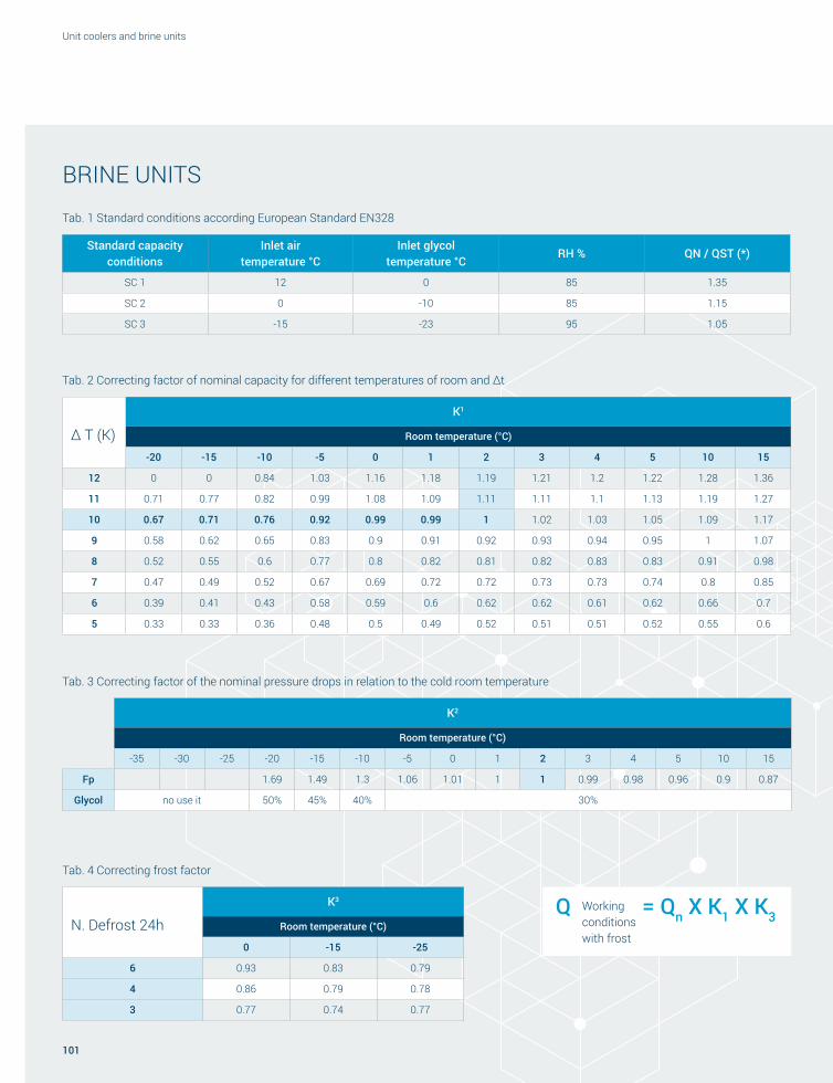
101
Unit coolers and brine units
N. Defrost 24h
K3
Room temperature (°C)
0 -15 -25
6 0.93 0.83 0.79
4 0.86 0.79 0.78
3 0.77 0.74 0.77
Standard capacity conditions
Inlet air temperature °C
Inlet glycol temperature °C
RH % QN / QST (*)
SC 1 12 0 85 1.35
SC 2 0 -10 85 1.15
SC 3 -15 -23 95 1.05
Tab. 1 Standard conditions according European Standard EN328
Δ T (K)
K1
Room temperature (°C)
-20 -15 -10 -5 0 1 2 3 4 5 10 15
12 0 0 0.84 1.03 1.16 1.18 1.19 1.21 1.2 1.22 1.28 1.36
11 0.71 0.77 0.82 0.99 1.08 1.09 1.11 1.11 1.1 1.13 1.19 1.27
10 0.67 0.71 0.76 0.92 0.99 0.99 1 1.02 1.03 1.05 1.09 1.17
9 0.58 0.62 0.65 0.83 0.9 0.91 0.92 0.93 0.94 0.95 1 1.07
8 0.52 0.55 0.6 0.77 0.8 0.82 0.81 0.82 0.83 0.83 0.91 0.98
7 0.47 0.49 0.52 0.67 0.69 0.72 0.72 0.73 0.73 0.74 0.8 0.85
6 0.39 0.41 0.43 0.58 0.59 0.6 0.62 0.62 0.61 0.62 0.66 0.7
5 0.33 0.33 0.36 0.48 0.5 0.49 0.52 0.51 0.51 0.52 0.55 0.6
Tab. 2 Correcting factor of nominal capacity for different temperatures of room and Δt
K2
Room temperature (°C)
-35 -30 -25 -20 -15 -10 -5 0 1 2 3 4 5 10 15
Fp 1.69 1.49 1.3 1.06 1.01 1 1 0.99 0.98 0.96 0.9 0.87
Glycol no use it 50% 45% 40% 30%
Tab. 3 Correcting factor of the nominal pressure drops in relation to the cold room temperature
Tab. 4 Correcting frost factor
Workingconditionswith frost
Q = Qn X K1 X K3
BRINE UNITS

Roen Est Heat exchangers and more
102
IDENTIFICATION CODE
CCL35
Type Tipo Typ Type Tipo Тип
K Commercial cubic
Cubici commerciali
Kubische luftverdampfer für den gewerbebereich
Cubiques commerciaux
Cúbicos comerciales
Кубические коммерческие
C Commercial cubic
Cubici commerciali
Kubische luftverdampfer für den gewerbebereich
Cubiques commerciaux
Cúbicos comerciales
Кубические коммерческие
I Industrial cubic
Cubici industriali
Kubische luftverdampfer für den industriebereich
Cubiques industriels
Cúbicos industriales
Кубические промышленные
D Double flow Doppio flusso Doppelfluss-verdampfer Double flux Doble flujo Двухпоточные
S Slanted Angolari Eckverdampfer Angulaires Angulares Угловые
F Fruit cooler Fruit cooler Obstkühler Fruit cooler Fruit cooler Охладители для фруктов
BF Blast freezer Blast freezer Blast freezer Blast freezer Blast freezer Blast freezer
UC Centrifugal unit coolers
Aeroevaporatori centrifughi
Luftverdampfer mit Radialgebläse
Évaporateurs ventilés centrifuges
Evaporadores centrífugos
Центробежные воздухоохладители
Fan motor diameter
Diametro ventilatori Gebläsedurchmesser
Diamètre ventilateurs
Diámetro ventiladores
Диаметр вентиляторов
20 Ø 200
25 Ø 250
30 Ø 300 / Ø 315
35 Ø 350
45 Ø 450
50 Ø 500
63 Ø 630
Refrigerant Refrigerante Kühlmittel Réfrigérant Refrigerantes Хладагента
C/D Cooler (Evaporator)
Cooler (Evaporatore)
Cooler (Luftverdampfer)
Cooler (Évaporateur)
Cooler (Evaporador)
Охладитель (Испаритель)
B Brine (Water – Glycol)
Brine (Acqua – Glicol)
Brine (Wasser – Glykol)
Brine (Eau – Glycol)
Brine (Agua – Glicol)
Рассольный охладитель (Вода – Гликоль)
Fin spacing
Passo alette Lamellenabstand Pas
ailettesPaso aletas PШаг ребер
3,0
mm
Type S Tipo S Typ S Type S Tipo S Тип S
4,0-4,5 Type H Tipo H Typ H Type H Tipo H Тип H
6,0 Type M Tipo M Typ M Type M Tipo M Тип M
7,0 Type N Tipo N Typ N Type N Tipo N Тип N
8,0 Type L Tipo L Typ L Type L Tipo L Тип L
10,0 Type V Tipo V Typ V Type V Tipo V Тип V
12,0 Type I Tipo I Typ I Type I Tipo I Тип I
6,0-12,0 Type D Tipo D Typ D Type D Tipo D Тип D

103
Unit coolers and brine units
4084ME
Number of rows
Numero Ranghi
Anzahl Kreisläufe
Nombre de rangées
Número Rangos
Количество рядов
04 4 Rows 4 Ranghi 4 Kreisläufe 4 Rangées 4 Rangos 4 Ряды
06 6 Rows 6 Ranghi 6 Kreisläufe 6 Rangées 6 Rangos 6 Ряды
08 8 Rows 8 Ranghi 8 Kreisläufe 8 Rangées 8 Rangos 8 Ряды
10 10 Rows 10 Ranghi 10 Kreisläufe 10 Rangées 10 Rangos 10 Ряды
12 12 Rows 12 Ranghi 12 Kreisläufe 12 Rangées 12 Rangos 12 Ряды
Number of fan motors
1 = 1 2 = 2 3 = 3 ecc.
Numero ventilatori
Anzahl Gebläse
Nombre de ventilateurs
Número ventiladores
Количество вентиляторов
E Electric defrost Sbrinamento elettrico Elektrische Abtauung Dégivrage électrique Desescarche eléctrico Электрическое оттаивание
N No defrost Nessuno sbrinamento Keine Abtauung Sans dégivrage Cero desescarche Без оттаивания
W Water defrost Sbrinamento ad acqua Wasserabtauung Dégivrage à l’eau Desescarche por agua Оттаивание водой
H Hot gas defrost Sbrinamento a gas caldo Heißgasabtauung Dégivrage par
gaz chaudDesescarche por
gas calienteОттаивание
горячим газом
Fan motor power supply
Alimentazione ventilatori
Stromversorgung Gebläse
Alimentation ventilateurs
Alimentación ventiladores
Питание вентиляторов
4 4 Poles 4 Poli 4 Polung 4 Pôles 4 Polos 4 Полюсы
6 6 Poles 6 Poli 6 Polung 6 Pôles 6 Polos 6 Полюсы
M Single-phase Monofase Einphasen Monophasé Monofase Однофазный
T Three-phase Trifase Dreiphasen Triphasé Trifase Трехфазный
The capacities which are indicated in the tables of the varies product ranges are calculated in wet conditions.Le capacità indicate nelle tabelle di rese per le varie gamme sono calcolate in condizioni umide. Die in den Leistungstabellen der verschiedenen Baureihen angegebenen Leistungswerte wurden in feuchter Umgebung berechnet. Les capacités indiquées dans les tableaux de rendements pour les différentes gammes sont calculées en conditions humides. Las capacidades indicadas en las tablas de rendimiento de las diferentes gamas se han calculado en condiciones de humedad. Значения производительности, указанные в таблицах эффективности для различных серий, рассчитаны во влажных условиях.
Codice di identificazione Id-Code Code d’identification Código de identificación Идентификационный код

Roen Est Heat exchangers and more
104
Graphic design: Gruppo PragmaCopywriting: Francesca GattiPrint: Tecno Copy Buri
Last update: February 2018


3
UN
IT C
OO
LERS
AN
D BR
INE
UN
ITS
REV.
01/
2018
Roen Est S.p.A.Via dell’Industria, 434077 Ronchi dei LegionariGorizia — Italy
T. +39 0481 474140F. +39 0481 [email protected]
www.roenest.com