Embed Size (px)
Citation preview

3. ARMATURE VOLTAGE AND GOVERING EQUATIONS
1). Armature Voltage(电枢中的感应电势)The induced voltage in a conductor is
)(1lvBe xx Then the induced voltage across armature terminal is
)2(2
1
2
1
2
1
aN
x
aN
x
aN
xa BlvlvBeE
Let Bp express average flux density under one pole.
0)3()(
1dxxBBp
)4(2
2
1p
aN
x Ba
NB

From Eqs. (2) and (4),
)5(pa Ba
NlvE
Let )6(60
pnv
)7(lA
Bp
Substituting Eqs. (6) and (7) into Eqs. (5) and simplifying,
)8(nCE ea
a
pNCe 60
where --- constant
nCE ea
Question : If saturation appears in magnetic field, will Ea become larger or smaller?
Note: Ea exists both in generator and in motor.
In generator, Ea produces armature current. It is called generated emf or positive voltage.
In motor, supply voltage U produces armature current and Ea opposes current to flow into armature winding. In this case it is called back emf or negative voltage.
2). Governing Equations of steady-state operation
Generator :
Example: Separately excited generator
• Governing equation of armature circuit
saaa URIEU 2where aR --- resistant of armature winding
VU s 22 --- voltage drop caused by brush contact resistant
• Features : (1). UEa (2). Ia is produced by Ea and has the same direction as Ea.
Ea is positive voltage.(3). Torque T is called negative torque because it oppose n.
• The total equations are
II
IRU
IRU
URIEU
a
L
fff
saaa 2
MotorExample: Separately excited motor
• Features : (1). UEa (2). Ia is produced by U and has the opposite direction from Ea.
Ea is negative voltage.
(3). Torque T is called positive torque because it produces n.
• Governing equation of armature circuit
saaa URIEU 2• Total equations
II
IRU
URIEU
a
fff
saaa 2
Summary
Before writing governing equations, please draw schematic diagram according to excitation modes and then give correct reference direction in terms of operation modes.
Example: Shunt generator and shunt motor

4. POWER FLOW AND EFFICIENCY
1). Losses
• Copper loss: armature circuit loss
field circuit loss
brush loss
aaa RIp 2)( 22
sasfff RIpRIp
asb IUp 2
• Core Loss fep 3.12 fB
• Mechanical loss --- against windage and friction
mp
• Additional loss (stray loss)
--- cannot be computed accurately
2)%1~5.0( Pp
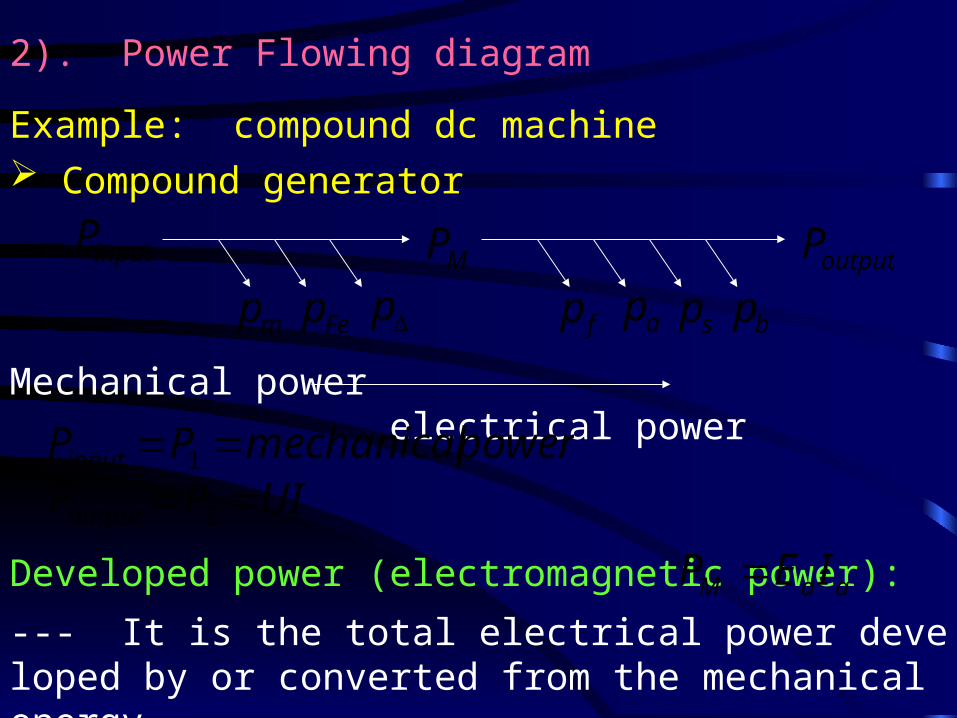
2). Power Flowing diagram
Example: compound dc machine Compound generator
inputP
mp Fep pMP
fp ap sp bpoutputP
Mechanical power electrical power
Developed power (electromagnetic power): aaM IEP --- It is the total electrical power developed by or converted from the mechanical energy.
powermechanicalPPinput 1
UIPPoutput 2
bsafM
bsafM
FemM
ppppPpPP
PppppP
pppPP
12
2
1
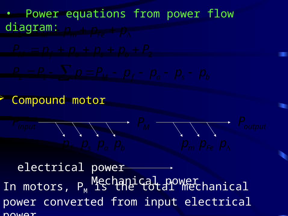
• Power equations from power flow diagram:
Compound motor
inputP
mp Fep pMP
fp ap bp
outputP
sp
electrical power Mechanical power
In motors, PM is the total mechanical power converted from input electrical power.

(3). Efficiency
%1001
2 P
P
5. DEVELOPED TORQUE (ELECTROMAGNETIC TORQUE)
The electromagnetic force acting on a conductor is
cxx liBF where ic is the current of conductor.
The force on the total conductors under each pole is
p
N
cxp liBF1

The force on all conductors of armature winding is
)1(1
pN
cxp liBppFF
The developed torque produced by armature winding is
)2(2
DFT
where D is the outer diameter of rotor.
Let
)4(
)3(
1p
pN
x
ac
Bp
NB
a
Ii
)6(
)5(
p
D
lBp
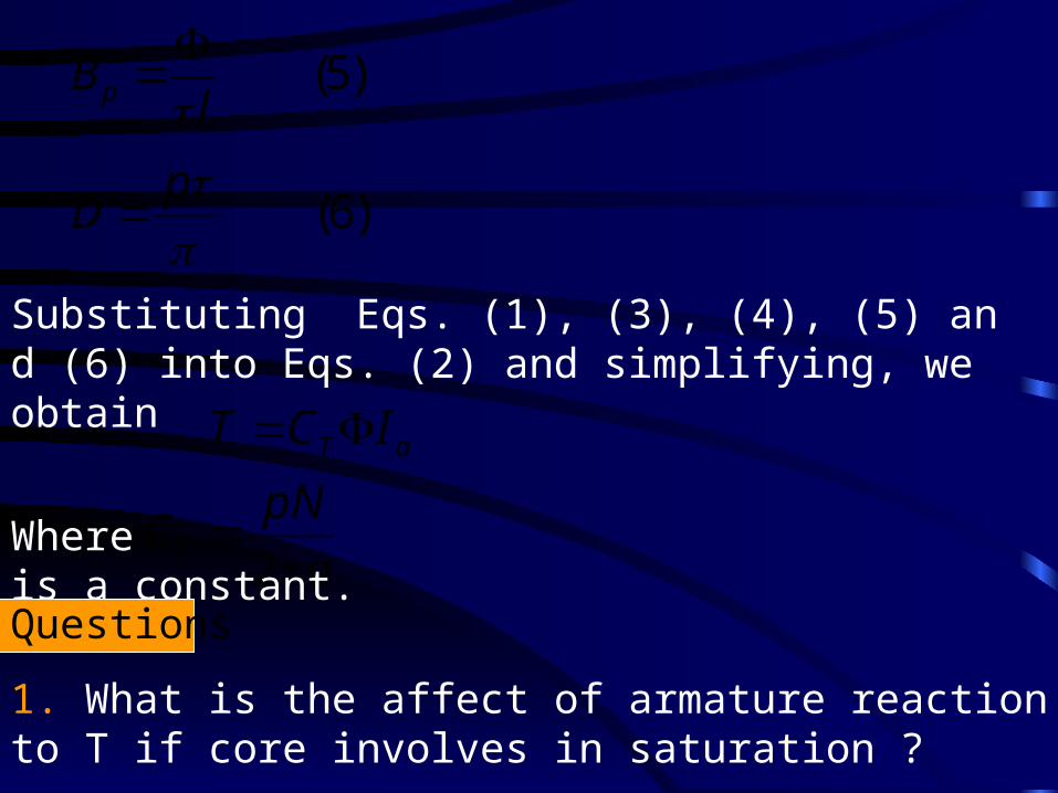
Substituting Eqs. (1), (3), (4), (5) and (6) into Eqs. (2) and simplifying, we obtain
aT ICT
a
pNCT 2
Where is a constant.
Questions
1. What is the affect of armature reaction to T if core involves in saturation ?
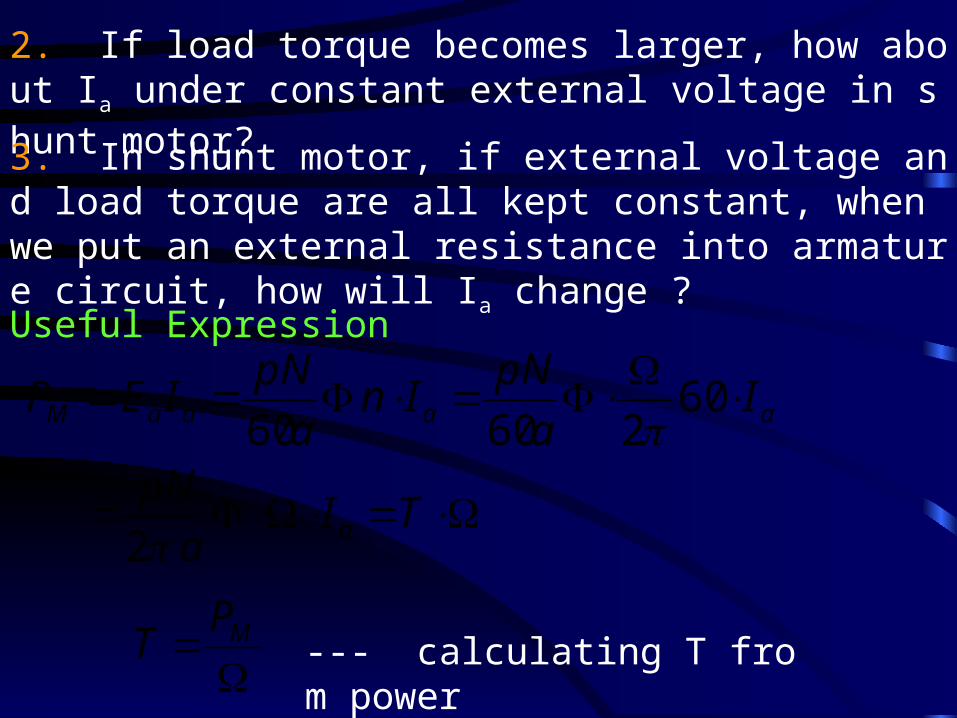
2. If load torque becomes larger, how about Ia under constant external voltage in shunt motor?
3. In shunt motor, if external voltage and load torque are all kept constant, when we put an external resistance into armature circuit, how will Ia change ?
Useful Expression
TIa
pN
Ia
pNIn
a
pNIEP
a
aaaaM
2
6026060
MPT --- calculating T from power
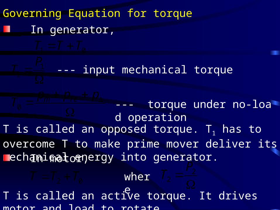
Governing Equation for torque
In generator,
01 TTT
pppT Fem
0 --- torque under no-load operation
1
1
PT --- input mechanical torque
T is called an opposed torque. T1 has to overcome T to make prime mover deliver its mechanical energy into generator.
In motor,
02 TTT
22
PTwhere
T is called an active torque. It drives motor and load to rotate.