Embed Size (px)
Citation preview
AIRORFT C IRCUL.RS
iTIO1LAD,IS3RY COITTE FOR ARONTJTICS
No. 133
THE HANRIOT H 431 :ILITY AIRPLANE (FRENCH)
A Generri Purpose Biplane
3 aw
'ashinton January, 1931
https://ntrs.nasa.gov/search.jsp?R=19930090355 2018-07-15T05:26:16+00:00Z
NATIONAL ADVISORY COviMITTEE FOR AERONAUTICS
AIRCRAFT CIRCULAR NO. 133
THE HANRIOT H 431 ILIARY AIRPLANE . (FREN-CH)*
A General Purpose Biplane
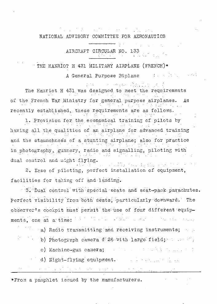
The Hanriot H 431 was designed. to meet the requirements
of the French War Ministry for general purpose airplanes. As
recently established,, these requirements are as follows.
1. Provision for, the economical training of pilots by
haying all the qualities of an airplane for advanced training
and the staunchness of a stunting airplane; also for practice
in photography, nnery, radio and signalling, piloting with
dual control and night 1ying. .
2. Ease of piloting, perfect installation of equipment,
facilities for taking off and '1ding.
3. Dual cortrol iri sp ecal seats and seat-pack-.parachutes.
Perfect 'vi'sibi1it 'from The
observe-,,2 8 cockpit must perni the'•üse of four different equip-
meit, one at a time: ' . •.. ...... .. .' ' . ..
a) Radio' trarsmitting 'and r'écivi'ng instruments;
b) Photogrsh caerä •f• 26With• large..' fiei;'
c) Machine-gun camera; ............' '. ':. .......' d) 11igh't-f'lying equipmënt. '' '•.. ... '..'.
*From a pamphlet issued by the manufacturers.
2 N.A.C.A. Aircraft Circular No. 133
4. Permanent armament:
a) An O.P.L. bomb sight;
b) A Lewis twin machine gun on ring mount T.O.7 with
300 cartridges:
c) An S.T.A. sight support;
d) Apparatus for signalling with rockets.
5. Radius of action of 450 km (280 miles) in still air.
The airplane carries fuel for 2.5 hours flight at full power.
The fuel tank can be emptied quickly, but is not protected.
Due to its good flight qualities, and in particular to its
easy controllability and maneuverability, it can be used as a
training plane for preparing less experienced pilots for opera-.
ting military airplanes (Figs. 1, & 3).
Description
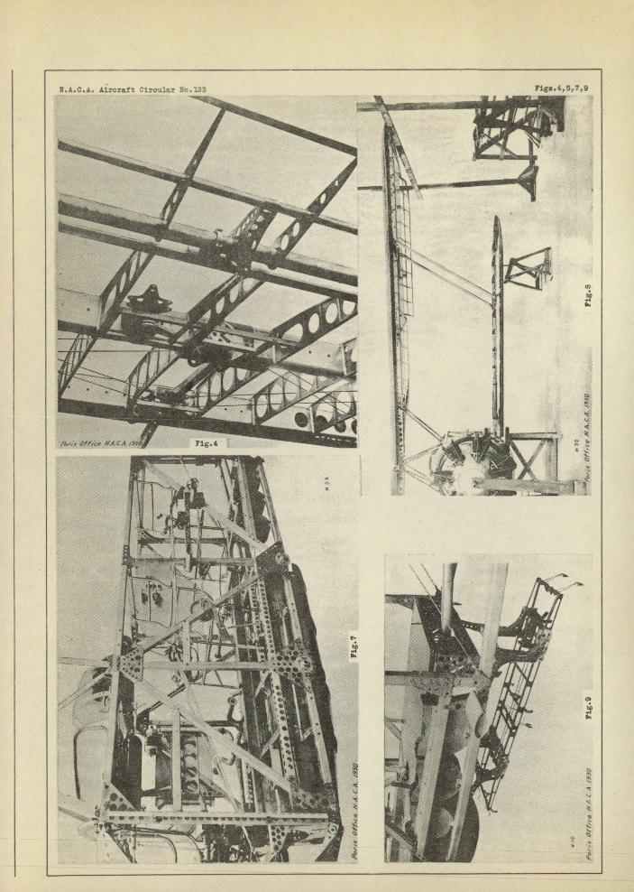
L_•Wings. The wings have a positive stagger, duralu.min
struts, and brace wires of high-resistance steel. The wing
structure is composed of duralumin spars and compression mem-.
bers with steel brace wires. The ribs are wood. The ailerons
are controlled by cables running over ball-bearing pulleys
(Figs. 4 05). The wing structure was approved by the French
Government February 4, 1928.
2. Fuselage.- The fuselage structure is rectangular and
composed of four tubular longerons of duralumin, with cross-
pieces and uprights of the same material. It is sheathed-
N.A.C.A. Aircraft Circulr No.133 3
throughout it entire length with dutalumin plates which can be
quickly removed, thus facilitating theupkeep of the airplane
andthe instllat±on of the various equipments (Figs. 6, 7, 8
&9)
• 3. Lending gear, This is fcmed by two lateral V stru.ts.
The sandow shock absorbers can be readily exchanged (Fig. 10).
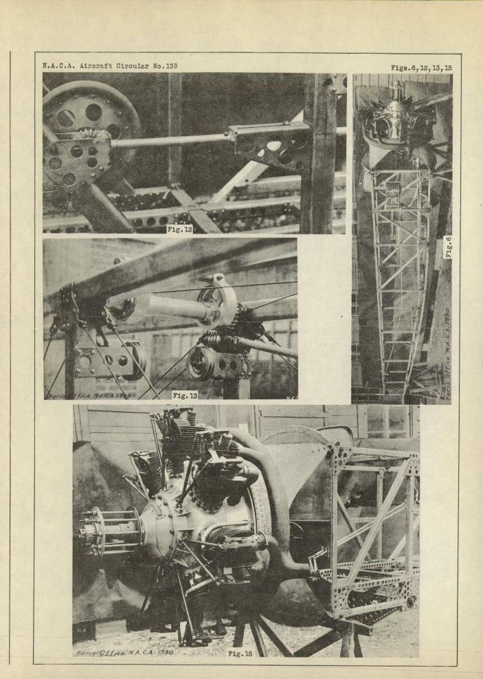
4. Tail surfaces.- The tail surfaces are constructed of
duralumin with fabric covering. Each empennage consists of a
fixed and a movable component (Fig. 11); The stabilizer is
adjustable during flight (Figs. 12, 13 & 141 while the fin can
be adjusted on the ground.
5. Controls;- The elevator control is perfectly rigid,
being mounted on ball bearings with a ball-and-socket joint.
The rudder and aileron tables are perfectly flexible and run
over large grooved ball-bearing pulleys.
6. Poweral_ant.- The H 431 io eqiii p sed with a 240 hp
Lorraine air-cooled engine. Other engines of similar char-
acteristics can bc used. The engine mount is sheet duralumin
and is attached to the front end of the fuselge by four ball-
and-docket jints (Figs. 1-4 ,16 & 17). A fire extinguisher
and a starter axe provided.
7. Tanks.- The dura1umii fuel tanks are placed in the
bottom of the fuselage an can be dropped at the will of the
pilot. The fuel is supplied by pump. The copper oil tank is
placed over the engine.
4 T.A.C.A. Aircraft Circular No. 133
Principal Charact e r i st i cs of the H 431
The H 431 has exceptional flight characteristics, due to
the form o.f its wing structure. It is a remarkable glider.
Due to the shape of the wing profile, the large gap and stag-
ger it has an aerodynamic efficiency of the first order. This
assures great facility in taking off and landing and excellent
behavior of the airplane. when flying at low speed. The stagger
of the wings, the cutaway's in the wings and the relatively high
cabana afford a remarkable visibility upward, forward and down-
ward.
The 240 lip Lorraine engine, which has demonstrated its
reliability on commercial lines, has made possible a very com—
pact airplane. The pilot and observer can communicate orally
with each other. Its extreme compactness, together with its
perfect balance and the efficacy of its controls, explains its
remarkable aptitude for stunt flying. It. can make the most
difficult and dangerous evolutions with impunity. Its safety
has been demonstrated by severe static tests. Lastly, its
equipment amply satisfies all exigencies.
The H 431 is equipped with dual control. The spacious
observer's cockpit enables the simultaneous installation of
radio, photographic and night—flying equipment. The supports
for all the instruments are mounted permanently on the air-
plane and all.four installations can be used during the same
flight.
N.A..C..A. Aircraft Ciicular No. '133 5
In short, the H 431 provides economically, in time of
peace, for the training of pilots and Observers, while, in
time 0±' war, its excellent equipment enables it to perform
all sorts of observation work of secondary importance.
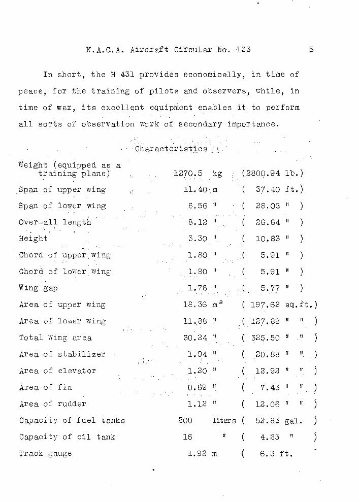
Characteristics :.'•
Weight (equipped as a training plane) , 1270.5 kg (2800.94 lb.)
Span of upper wing 11.40 m ( 37.40 ft.)
Span of lower wing 8.56 " ( 28.08 " )
Over-all length 8.12 ( 26 64 )
Height 330 U ( 10.83 )
Chord of upper wing 1.8011 .( 5.91 it)
Chord of lower wing 1.80 ( 5.91 )
Wing g ap , 1.76 " ,. .( 5•77 )
Area of upper wing 18.36 m2(
197.62 sq.t.)
Area of lower wing , 11.88 ( 127.88 U)
Total wing area ' 30.24•1 ( 325.50 )
Area of stabilizer ' 1.94 ." (. 20.88 . )
Area of elevator 1.20 " ( 12.92 5
Area of fin 0.69 ( 7.43
Area of rudder 1.12 " ( 12.06
Capacity of fuel tanks 200 liters ( 52.83 gal. 5
Capacity of oil tank 16 " ( 4.23 " 3
Track gauge 1.92 rn ( 6.3 ft. -
6 N.A.C.A. Aircraft Oicu1ai' No. 133
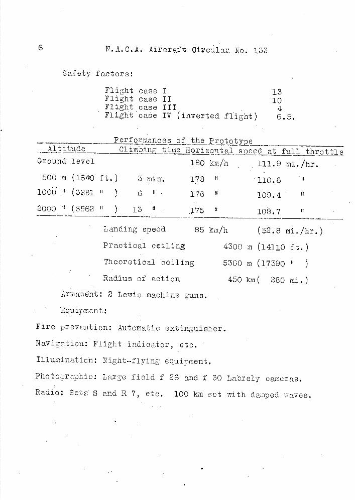
Safety factors:
Flight case I 13 Flight case II 10 Flight case III 4 Flight case IV (inverted flight) 6.5.
erfoices of the Prototy-pe Altitude Climbing_ time _Hizon 4 alp&ed at full throttle
Ground level 180 km/h 111.9 mi./hr.
soo m (1640 ft.) 3 min. 178 110.6
1000 (3281 ' ) 6 176 109.4
2000 11 (6562 It ) 13 " 75 108.7
Landing speed
Practical ceiling
Theoretical ceiling
Radius of action
85 ke/h (52.8 mi./hr.
4300 in (141 10 ft.)
5300 m (17390 U )
450 In( 280 mi.)
Armeajent: 2 Lewis machine guns.
Equipment:
Fire prevention: Automatic extinguisher.
Navigation: Flight indicator, etc.
Illumination: Night—fl y ing equipment.
Photoraphic: Large field f 26 and f 30 Labrely cameras.
Radio: Sets S and -R 7, etc. 100 km set with deaaped waves.
N.A.G.A Aircraft Circular No. 133
7
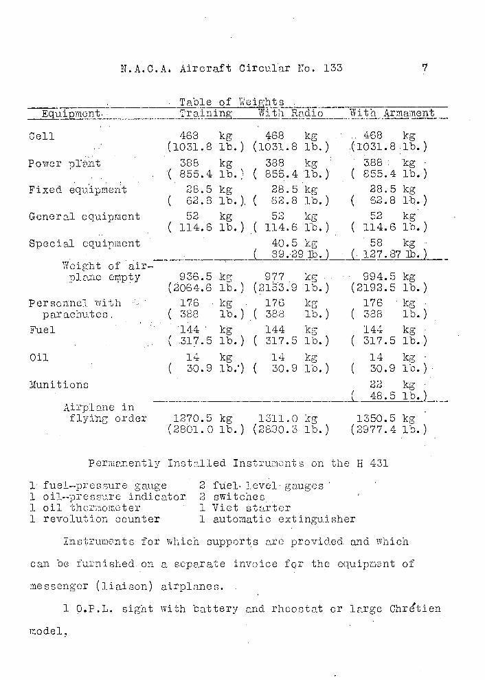
Table of Equipnt Traiing With Radio With Armament
468 kg (1031.8 lb.)
388 kg .( 855.4 lb.)
28.5 kg ( 62.8 lb.)
52 kg ( 114.6 lb.)
468 kg (1031.8.1b.)
388: kg ( 855.4 lb.)
28.5 kg ( 62.8 lb.)
52 kg ( 114.6 lb.)
58 kg (127.87Th.)
936.5 kg (2064.6 lb.)
1 7 6 kg ( 388 lb.)
144 kg ( .317.5 lb.)
TA 1
30.9 lb;)
468kg (1031.8 lb.)
388 kg ( 855.4 lb.)
28.5 kg ( 82.8 lb.)
52 kg ( 114.6 lb.)
40.5 kg C '99.239 1b.
977 • kg.. (2l3.9 lb.)
176 kg ( 388 lb.)
144 kg ( 317.5 lb.)
14 kg ( 30.9 lb.)
994.5 kg (2192.5 lb.)
176 kg ( 388 lb.)
144 kg ( 317.5 lb.)
14 kg 30.9 lb.)
22 kg 1'J_
Cell
Power prbnt
Fixed equipment
General equipment
Special equipment
Weight ofair-
')lane empty
Personnel with parachutes
Fuel
Oil
Munitions
Airplane in flying order 1270.5 kg 1311.0 kg 1350.5 kg
(2801.0 lb.) (2890.3 lb.) (2977.4 lb.)
Permanently Installed Instruncnts on the H 11,131
1 fuel-pressure gauge 1 oil-pressure indicator. 1 oil therioineter 1 revolution counter
2 fuel-level gauges 2 switches I Viet starter 1 automatic extinguisher
Instruments for which supports arc proviced and which
can be furnished, on a separate invoice for the equipment of
messenger (liaison) airplanes.
1 O.P.L. sight with battery and rheostat or large Chrtien
model,
8 N.A.C.A. Aircraft Circular No. 133.
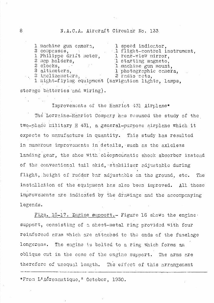
1 machine gun camera, 1 speed indicator, 2 compasses, .1 flight-control instrument, 1 Philippe drift meter, 1 rear-view mirror, 2 map holders, 1 starting magneto, 2 clocks, : 1 machine gun mount, 2 altimeters, 1 photographic camera, 2 i,nclinometrs 2 radio sets, 1 night-flying. equipment (navigation lights, lamps,
storage batteries and wiring).
Improvements of the lianriot 431 Airplane*
TO Lorraine.-Hanriot Company has resumed the study of the
two-plade military H 431, a general-purpose airplane which it
expects to manufacture in quantity. This study has resulted
in numerous improvements in details, such as the axieless
landing gear, the shoe witho1opncümatic shock absorber instead
of the conventional tail skid, stabilizer adjustable during
flight, height of rudder bar adjustable on the ground, etc; The
installation of the equiimiient has also been improved. All these
improvements are indicated by the drawings and the accompanying
legends.
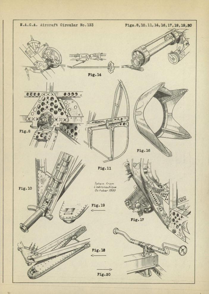
Fgs. 16-17. Eine support -,.- Figure 16 shows the engine
support, consisting of a sheet-metal ring provided with four
reinforced arms which arc attached to the ends of the fuselage
longerons. The engine is bolted to a ring which forms an
oblique cut in the cone of the engine support. The arms are
therefore of unequal length. The effect of this arrangement
*From L 1 Aronautique , lt October, 1930.
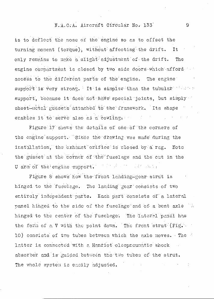
N.A.C:A. Aircraft Cfrduiar No, 133
is to deflect the nose of the 'engine so as to offset the
turning moment (torue)', wit ut affectinthe drift. It
only remains to mke a siight adjutntOf the drift. The
engine coriptmOnt is closed by two side doors .which:afford
accës to thá diffeent parts of the engine. The engine
suport is very strong. It is sinipler than the tubular ...
supot, bebause itdoeriohe specialjoints, but simply
sheetmcta1gu6sCtsattac1hCd to tnefreL1ewok. Its shape
enables it to serve also a a eowl-ing
Figure 17 shows the details of one o*f 'the corners of
the engine sUppoTt. Since the d:rawing was made during the
installation; the 0±htust orfic0 is' closed by: a•• rag. Note
the 1±sset: at th 1corner of :tho: fusele ge and the but in the
U arm o`f the engine -sup 'port . .•' .. . ' . .; . .
Figure a showO how the froht landiigceär strut is
hinged to the fuselage The landing ear consists of two
entirely ' indpedent parts. Each part consists 01 : a lateral
panel hinged to the side of the fuse1agethd bf• :t bent axle
hinged: to the center of the fuselagc The :Iatcrl 5bnbl has
Cr the forii of a V with the point down. The front strut (Fi.
10) consists of two tubes between which the axle roves. The
latter is. connected with a Haniot oloopneutid shock
absorber and is guided betwbn the to tubes of the strut.
The whold syste:1 is eacily adjusted.
10 N.A.C.A. Aircraft Circular No. 133
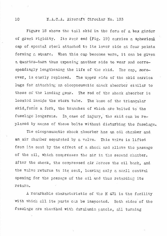
Figure 18 shows the tail skid in the form of a box girder
of great rigidity. Its rear end (Fig. 19) carries a spherical
cap of. special steel attached to its lower side at four points
forming a square. When this cap becofres worn, it can be given
a quarter-turn thus exposing another side to wear and corr'e-
spodingly lengthening the life of the skid. The cap, more-
over, is easily replaced. The upper side of the skid carries
lugs for attaching an oleo pneumatic shock absorber similar to
those of the landing gear. The rod of the shock absorber is
located, inside the stern tube. The base of the triangular
skid,forms a fork, the branches of which are bolted to the
fuselage longeroris. in case of injury, the skid can be re-
placed by means of these bolts without disturbing the fuselage.
The oleopneumatic shock absorber has an oil chamber and
an air chamber separated by a valve. This valve is lifted
from its seat by the effect of a shock and allows the passage
of the oil, which compresses the air in the second. chamber.
After the shook, the compressed air forces the oil back, and
the valve returns to its seat, leaving only a small central
opening for the passage of the oil and thus retarding its
return.
A remarkable characteristic of the H 431 is the facility
with which all, its p arts can be inspected. Both sides of the
fuselage are sieat.aed with duralumin panels, all turning
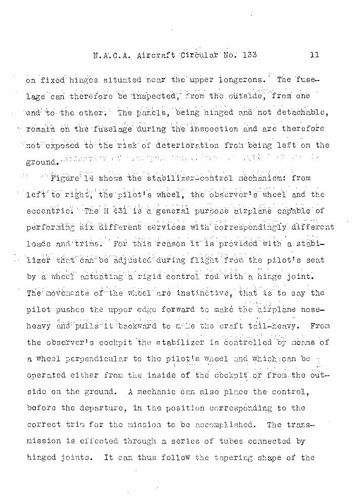
N.A.C.A. Aircraft 'Cirãüla To; 133 11
on fiedhingcs situated near the' u*pper longerons. The fuse-
• lagO c an thrforo bO 'inspected', - rorn th oüts'ide from one
end to : thè other Tho anOl, being hi an not detaôhable,
remain on the fuselage during he ihspedtion and are therefore
t• .: the risk of detriOation fro:ibeing left on the
ground.,*''-0
Fgure 14Iovis the tabi1izer- con trd1 mOchanlsm: from
• .L t : to ri11tthe-pilot" g. iheel, the obsod±VèrI s wheel and the
eccenticVThe H 43is a general purosëairplane capab1eof
perfor si affient services wti correspondingly diffeicnt
loads an d , tTirs. For tnis reason it is provided with a stabi-
1ize tt:ba1be adjüsted during f1iht froii the pilotts seat
by awhcciactuatinah rigid control rod witha hinge joint.
The moënontsofthe Whbel are instinctiv, that is' to say the
pilot pushes the upp er edge forward to make the aip1ane nose-
heavy dpu1e it backward to m:ke the craft tail-heavy. From
the observcrs coo' pit the stabilizer is cotro1leci.; deans of
a wheel perpendicular to the pi1.otS: '1hee1 and whioh;can be
oneratod cit er fib the inside of the cockt r ±roii the out-
side on the ground. A mechanic can also place the control,
before the dctarture, in the position corresponding to the
correct trim for the mission to be accomplished. The trans-
mission is effected through a series of tubes connected by
hinged joints. It can thus follow the tapering shape of the
12 N.A.C.A. Aircraft Circular No. 133
fuselage and dispense with special devices while retaining great
ease of operation. It actuates an endless screw which controls
a pinion integral with two eccentrics, the latter being hinged
to the front spar of the stabilizer which they move up or down.
There is no play, so that the effect is immediate and, because
of the rigidity, the stabilizer acquires no vibration.
Each-'rudder bar of the dual control (Fig. 20) consists of
a double crank, whose axis carries a pinion which is controlled
by an endless screw. The latter terminates in a key, by
turning which the pilot can elevate or depress the cranks at
will and thus adjust them to the length' of his legs.
The framework of both the stabilizer and elevator (Fig. 11)
consists of U—section ribs mounted on rectangular and round
tubes, thus affording great strength and lightness. The hinges
have ball bearings.
Figure 3 shows the annular cowling of the Mi .zar It type
of the Lorraine—Hanriot H 431.
Translation by Dwight M. Miner, National Advisory Committee for Aeronautics.
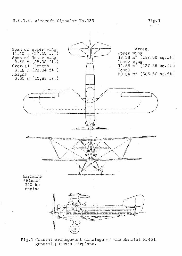
N.A.C.A. Aircraft Circular No.133
Fig. i
Span of upper wing Areas: 11.40 m (37.40 ft.) RZ ' Upper wine Span of lower wing 18.30 rn 2 (197.62 sq.ft. 8.56 in (28.08 ft.) / Lower win
Over-all leflgth 11.88 in 2 127.88 sq.ft.) 8.12 in (26.64 ft.) I Total
Height 4- 30.24 in 2 (325.50 sq.ft... 3.30 in (10.83 ft.)
1H _____
I'
4. cLJi1
tljvlizartf 240 hp engine
\ - - r---:.
Ic
c,)
Fig.l General arrangement drawings of tie :-ianriot H.431 general purpose airplane.
Figs. 2,.3 N.A.C.A. Aircraft Circulaz No.133
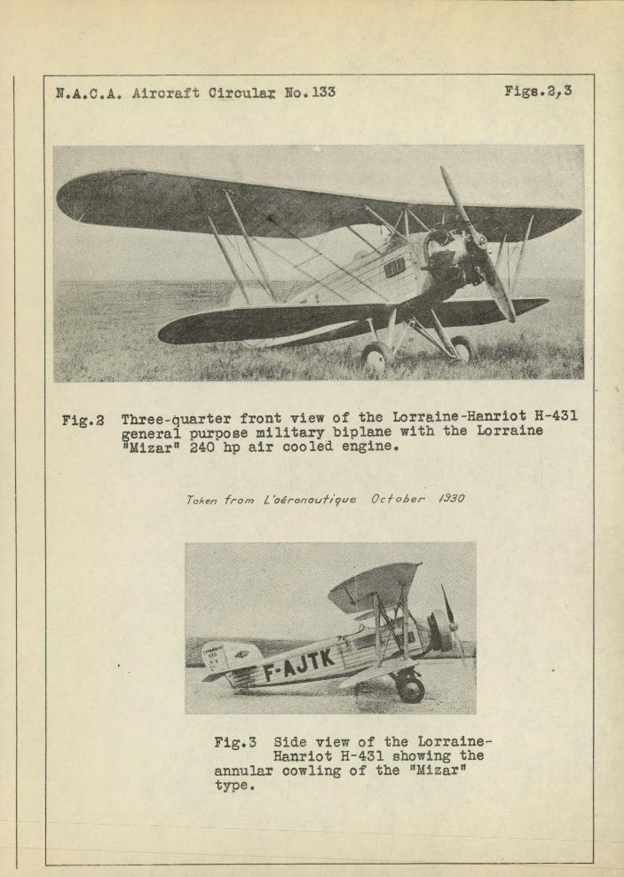
Fig.2 Three-quarter front view of the Lorraine-Hanriot H-431 general purpose military biplane with the Lorraine "Mizar 0 240 hp air cooled engine.
Ta.4er7 Iron? L'céronautque Oc/ohei- 1330
Fig.3 Side view of the Lorraine-Hanriot H-431 showing the
annular cowling of the "Mizar" type.
'"/ (2ft,( NA.C.A /,930 Fig. 15
-:
- L
H :
LVi4 .r