Embed Size (px)
Citation preview

© The Aerospace Corporation 2013
3-Axis Attitude Determination and Control of the AeroCube-4 CubeSats
Darren Rowen Rick Dolphus The Aerospace Corporation
Vehicle Systems Division 10 August 2013

2 [email protected] Control Analysis Department
Topics
• AeroCube History and Overview • Hardware • Attitude Determination and Control • Flight Software • Photos
4 [email protected] Control Analysis Department
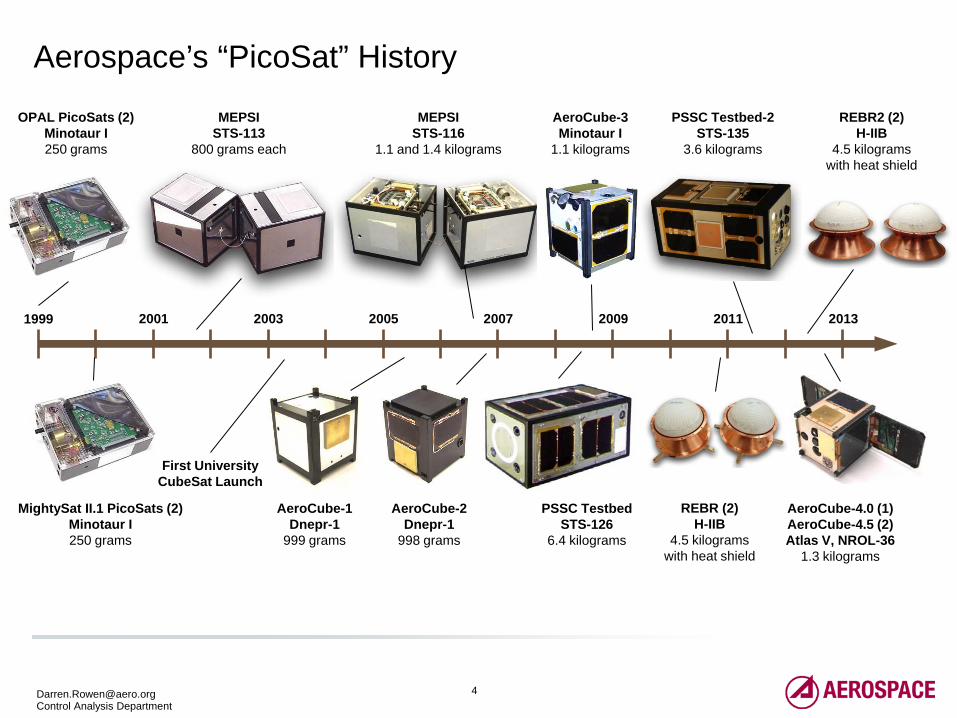
Aerospace’s “PicoSat” History
1999 2001 2003 2005 2007 2009 2011 2013
OPAL PicoSats (2) Minotaur I 250 grams
MEPSI STS-113
800 grams each
MEPSI STS-116
1.1 and 1.4 kilograms
AeroCube-3 Minotaur I
1.1 kilograms
PSSC Testbed-2 STS-135
3.6 kilograms
MightySat II.1 PicoSats (2) Minotaur I 250 grams
AeroCube-1 Dnepr-1
999 grams
AeroCube-2 Dnepr-1
998 grams
PSSC Testbed STS-126
6.4 kilograms
AeroCube-4.0 (1) AeroCube-4.5 (2) Atlas V, NROL-36
1.3 kilograms
First University CubeSat Launch
REBR2 (2) H-IIB
4.5 kilograms with heat shield
REBR (2) H-IIB
4.5 kilograms with heat shield
5 [email protected] Control Analysis Department
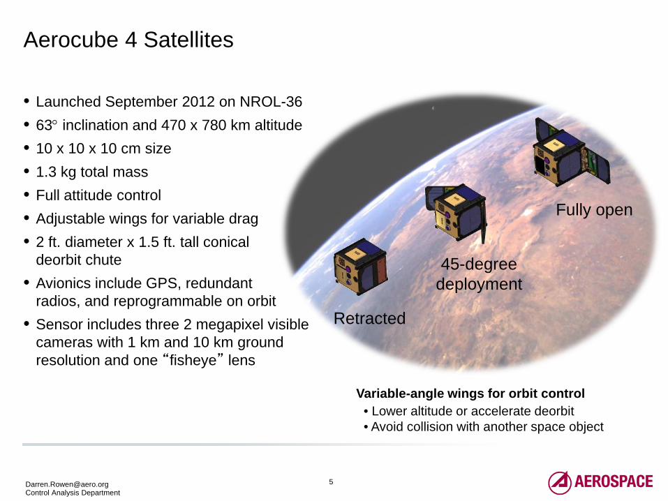
Aerocube 4 Satellites
Variable-angle wings for orbit control • Lower altitude or accelerate deorbit • Avoid collision with another space object
Retracted
45-degree deployment
Fully open
• Launched September 2012 on NROL-36 • 63° inclination and 470 x 780 km altitude • 10 x 10 x 10 cm size • 1.3 kg total mass • Full attitude control • Adjustable wings for variable drag • 2 ft. diameter x 1.5 ft. tall conical
deorbit chute • Avionics include GPS, redundant
radios, and reprogrammable on orbit • Sensor includes three 2 megapixel visible
cameras with 1 km and 10 km ground resolution and one “fisheye” lens
7 [email protected] Control Analysis Department
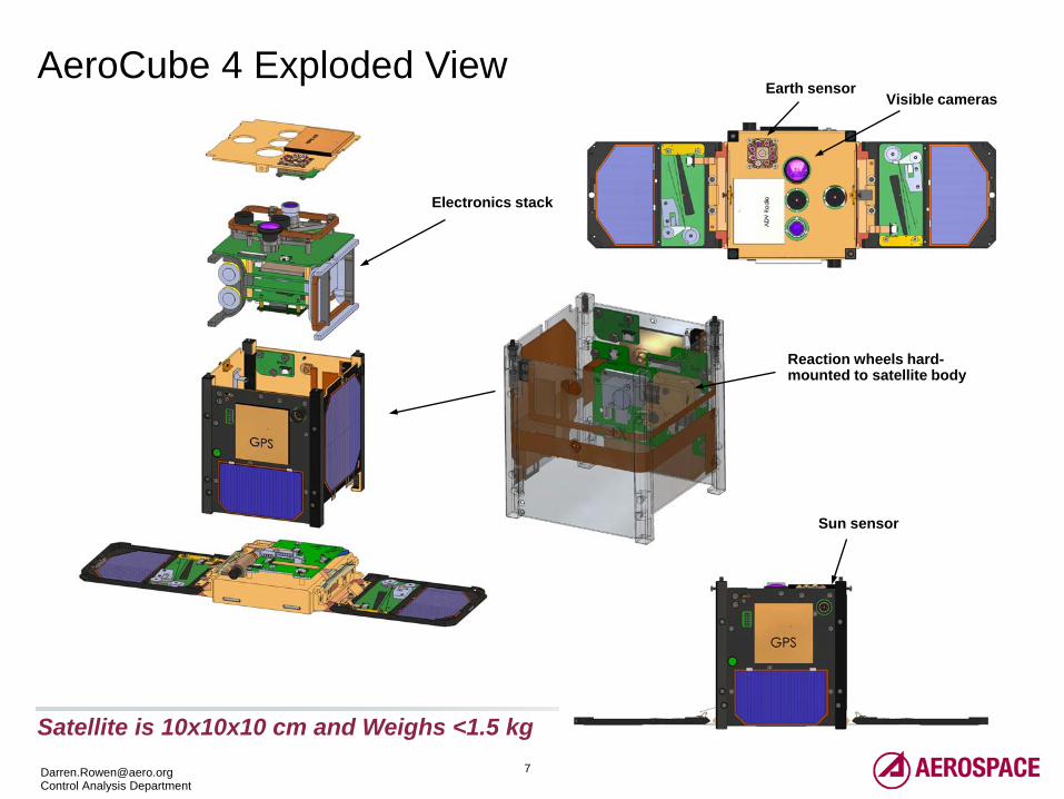
AeroCube 4 Exploded View
Satellite is 10x10x10 cm and Weighs <1.5 kg
Reaction wheels hard-mounted to satellite body
Sun sensor
Visible cameras Earth sensor
Electronics stack
8 [email protected] Control Analysis Department
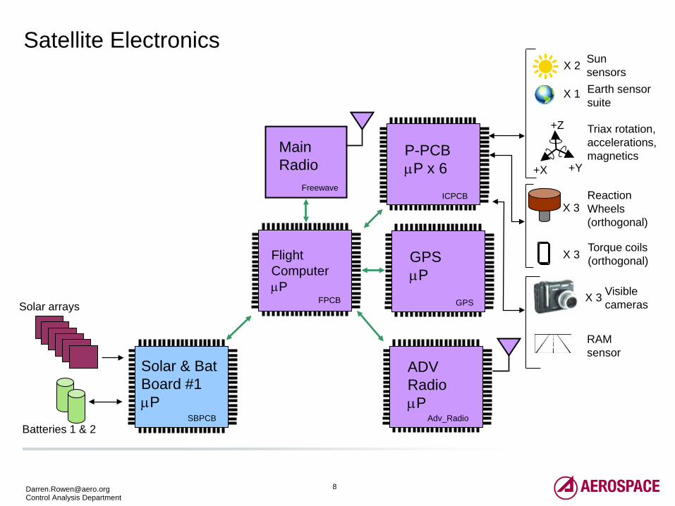
Satellite Electronics
Flight Computer µP
P-PCB µP x 6
SBPCB
ICPCB
Main Radio
Batteries 1 & 2
+Z
+Y +X
Triax rotation, accelerations, magnetics
FPCB
Freewave Reaction Wheels (orthogonal)
X 3
X 3 Visible cameras
Torque coils (orthogonal) X 3
X 2
X 1
Sun sensors Earth sensor suite
Solar & Bat Board #1 µP
GPS µP
GPS
ADV Radio µP
Adv_Radio
RAM sensor
Solar arrays
9 [email protected] Control Analysis Department
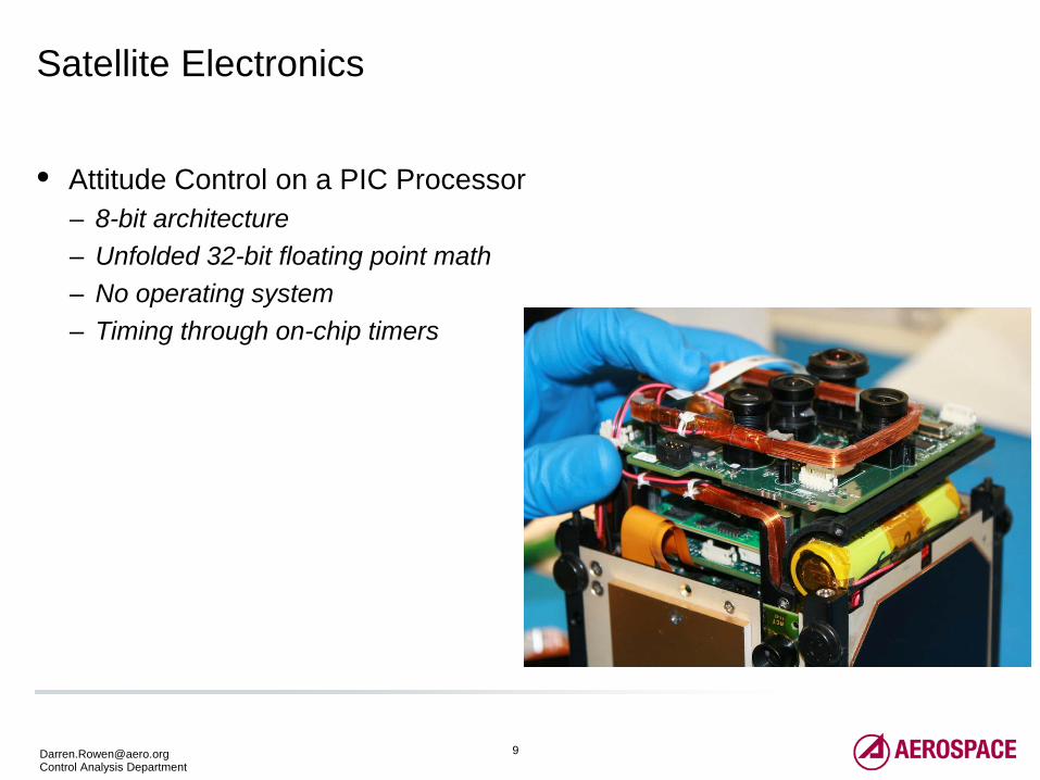
Satellite Electronics
• Attitude Control on a PIC Processor – 8-bit architecture – Unfolded 32-bit floating point math – No operating system – Timing through on-chip timers
11 [email protected] Control Analysis Department
Attitude Determination (1 of 2)
• Attitude sensors • Sun sensor • Earth sensor • Magnetometer
• Require 2 of 3 attitude sensors to get full 3-axis attitude (gyroless design) • Sun sensor alignment and calibration is based on ground
measurements/testing • Earth sensor alignment and calibration is fine-tuned on-orbit • Magnetometer biases recalculated on-orbit at beginning of each mission (using
attitude from Sun sensor and Earth sensor while nadir pointing) • Nadir pointing
• Use Sun & Earth • Off-nadir (including inertial pointing)
• Use Sun & Magnetometer (Earth sensor less accurate or unavailable off-nadir)
12 [email protected] Control Analysis Department
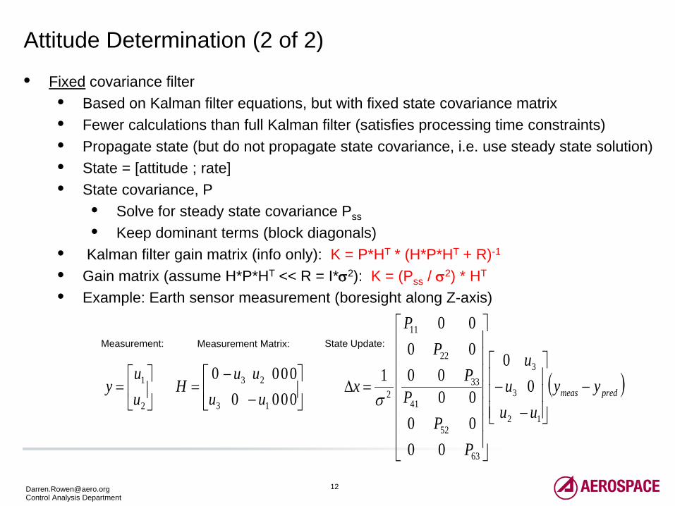
Attitude Determination (2 of 2)
• Fixed covariance filter • Based on Kalman filter equations, but with fixed state covariance matrix • Fewer calculations than full Kalman filter (satisfies processing time constraints) • Propagate state (but do not propagate state covariance, i.e. use steady state solution) • State = [attitude ; rate] • State covariance, P
• Solve for steady state covariance Pss
• Keep dominant terms (block diagonals) • Kalman filter gain matrix (info only): K = P*HT * (H*P*HT + R)-1
• Gain matrix (assume H*P*HT << R = I*σ2): K = (Pss / σ2) * HT
• Example: Earth sensor measurement (boresight along Z-axis)
( )predmeas yyu
u
uu
PP
PP
PP
x −
−−
=∆
1
3
2
3
63
52
41
33
22
11
2 00
000000
000000
1σ
−
−=
00
00
00
00
1
23
3 uuu
uH
=
2
1
uu
y
Measurement Matrix: Measurement: State Update:
13 [email protected] Control Analysis Department
Attitude Control
• 3-axis attitude control • PI control law • Actuators: Reaction wheels (speeds up to 100 KRPM)
• Momentum control • Momentum builds due to spacecraft dipole and atmospheric drag • Dump wheel momentum by applying coil torque = M x B • Earth magnetic field B
• B in ECI-frame is calculated using polynomial fit generated on ground and uploaded to spacecraft
• Map B to Body-frame using estimated attitude • Actuators: Magnetic torque coils (magnetic moment M)
15 [email protected] Control Analysis Department
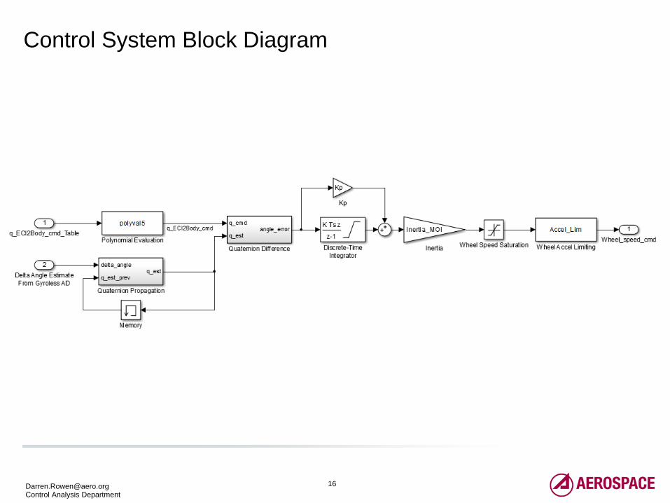
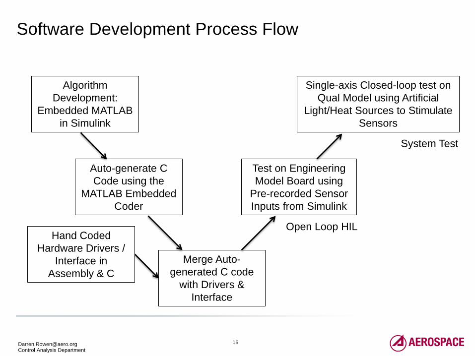
Software Development Process Flow
Algorithm Development:
Embedded MATLAB in Simulink
Auto-generate C Code using the
MATLAB Embedded Coder
Hand Coded Hardware Drivers /
Interface in Assembly & C
Merge Auto-generated C code
with Drivers & Interface
Test on Engineering Model Board using
Pre-recorded Sensor Inputs from Simulink
Single-axis Closed-loop test on Qual Model using Artificial
Light/Heat Sources to Stimulate Sensors
Open Loop HIL
System Test
17 [email protected] Control Analysis Department
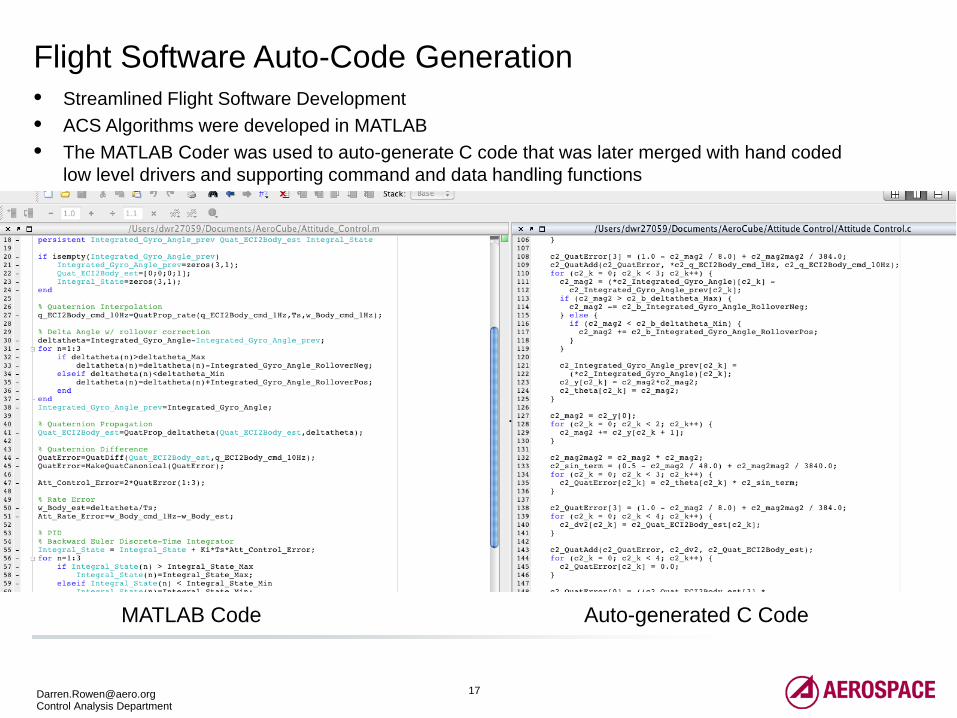
Flight Software Auto-Code Generation • Streamlined Flight Software Development • ACS Algorithms were developed in MATLAB • The MATLAB Coder was used to auto-generate C code that was later merged with hand coded
low level drivers and supporting command and data handling functions
Auto-generated C Code MATLAB Code
18 [email protected] Control Analysis Department
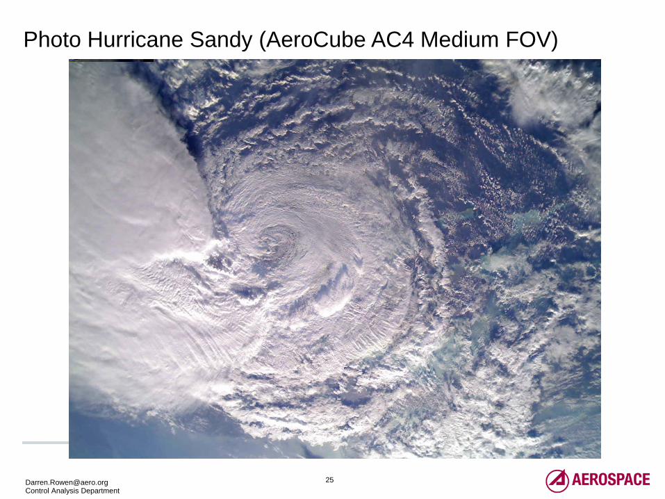
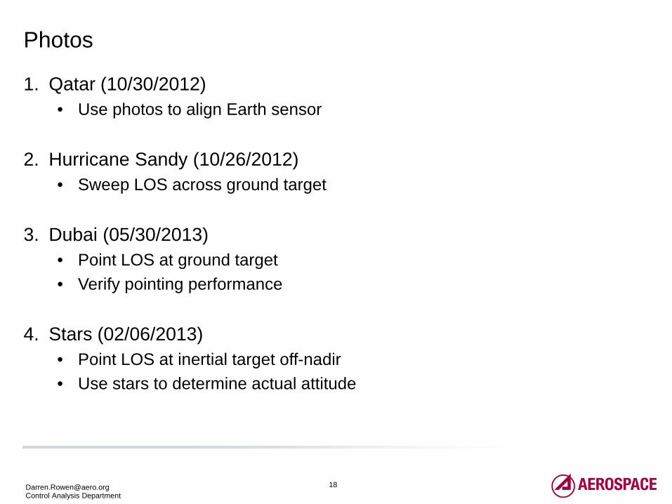
Photos
1. Qatar (10/30/2012) • Use photos to align Earth sensor
2. Hurricane Sandy (10/26/2012)
• Sweep LOS across ground target
3. Dubai (05/30/2013) • Point LOS at ground target • Verify pointing performance
4. Stars (02/06/2013)
• Point LOS at inertial target off-nadir • Use stars to determine actual attitude
19 [email protected] Control Analysis Department
Photo 1:
Qatar
(Using Photos to Align Earth Sensor)
20 [email protected] Control Analysis Department
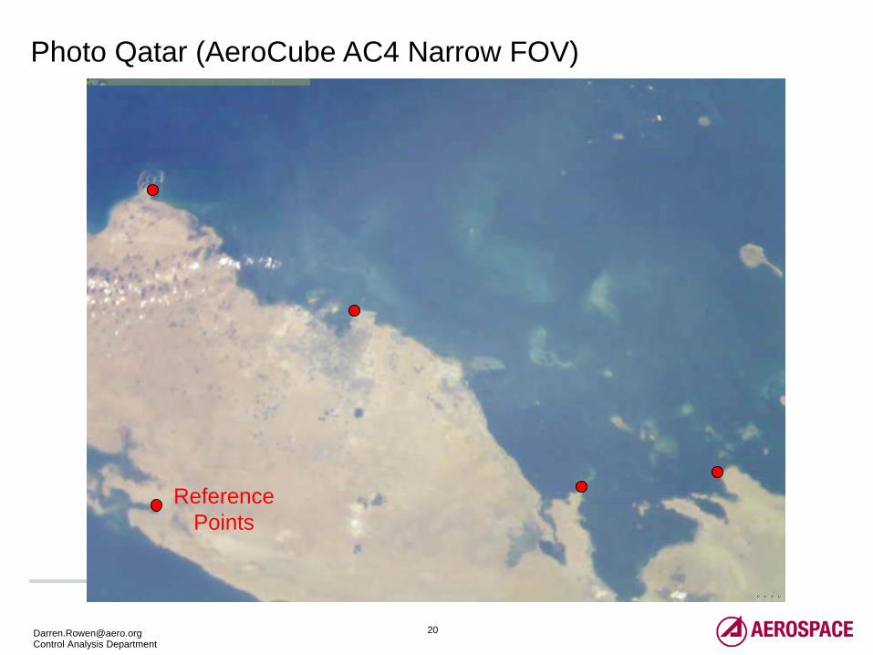
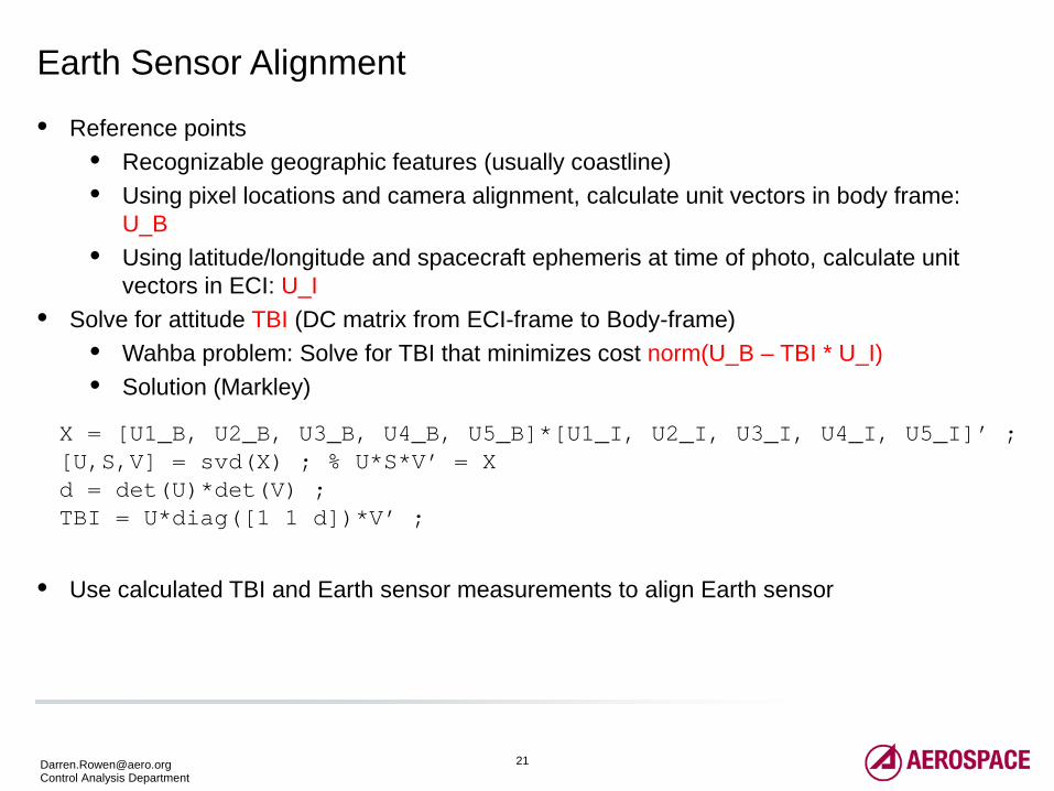
Photo Qatar (AeroCube AC4 Narrow FOV)
Reference Points
21 [email protected] Control Analysis Department
Earth Sensor Alignment
• Reference points • Recognizable geographic features (usually coastline) • Using pixel locations and camera alignment, calculate unit vectors in body frame:
U_B • Using latitude/longitude and spacecraft ephemeris at time of photo, calculate unit
vectors in ECI: U_I • Solve for attitude TBI (DC matrix from ECI-frame to Body-frame)
• Wahba problem: Solve for TBI that minimizes cost norm(U_B – TBI * U_I) • Solution (Markley)
• Use calculated TBI and Earth sensor measurements to align Earth sensor
X = [U1_B, U2_B, U3_B, U4_B, U5_B]*[U1_I, U2_I, U3_I, U4_I, U5_I]’ ; [U,S,V] = svd(X) ; % U*S*V’ = X d = det(U)*det(V) ; TBI = U*diag([1 1 d])*V’ ;
22 [email protected] Control Analysis Department
Photo 2:
Hurricane Sandy
(Sweep LOS Across GroundTarget)
23 [email protected] Control Analysis Department
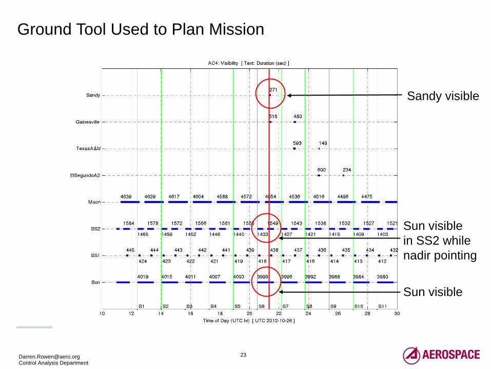
Ground Tool Used to Plan Mission
Sandy visible
Sun visible
Sun visible in SS2 while nadir pointing
24 [email protected] Control Analysis Department
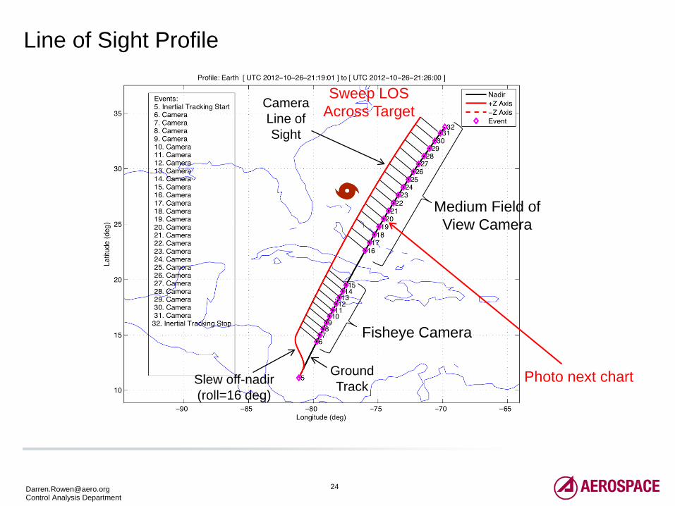
Line of Sight Profile
Medium Field of View Camera
Camera Line of Sight
Ground Track
Fisheye Camera
Slew off-nadir (roll=16 deg)
Sweep LOS Across Target
Photo next chart
26 [email protected] Control Analysis Department
Photo 3:
Dubai
(Point LOS at Ground Target, Verify Pointing Performance)
27 [email protected] Control Analysis Department
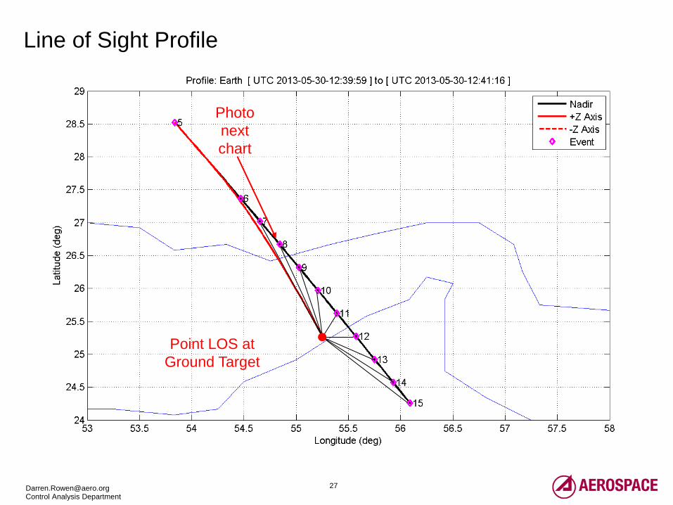
Line of Sight Profile
Point LOS at Ground Target
Photo next chart
28 [email protected] Control Analysis Department
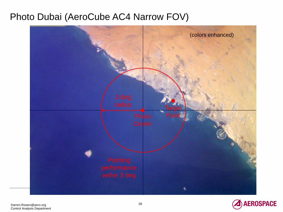
Photo Dubai (AeroCube AC4 Narrow FOV)
(colors enhanced)
3 deg radius
Pointing performance within 3 deg
Photo Center
Target Point
29 [email protected] Control Analysis Department
Photo 4:
Stars
(Point LOS at Inertial Target, Use Stars to Determine Actual Attitude)
30 [email protected] Control Analysis Department
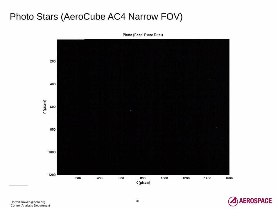
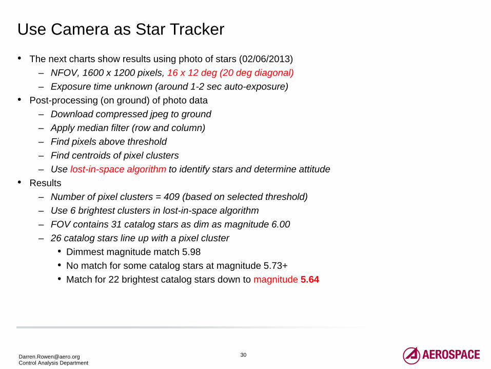
Use Camera as Star Tracker
• The next charts show results using photo of stars (02/06/2013) – NFOV, 1600 x 1200 pixels, 16 x 12 deg (20 deg diagonal) – Exposure time unknown (around 1-2 sec auto-exposure)
• Post-processing (on ground) of photo data – Download compressed jpeg to ground – Apply median filter (row and column) – Find pixels above threshold – Find centroids of pixel clusters – Use lost-in-space algorithm to identify stars and determine attitude
• Results – Number of pixel clusters = 409 (based on selected threshold) – Use 6 brightest clusters in lost-in-space algorithm – FOV contains 31 catalog stars as dim as magnitude 6.00 – 26 catalog stars line up with a pixel cluster
• Dimmest magnitude match 5.98 • No match for some catalog stars at magnitude 5.73+ • Match for 22 brightest catalog stars down to magnitude 5.64
32 [email protected] Control Analysis Department
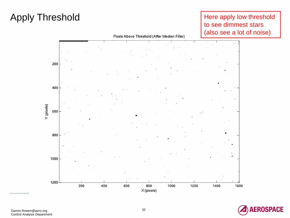
Apply Threshold Here apply low threshold to see dimmest stars (also see a lot of noise)
33 [email protected] Control Analysis Department
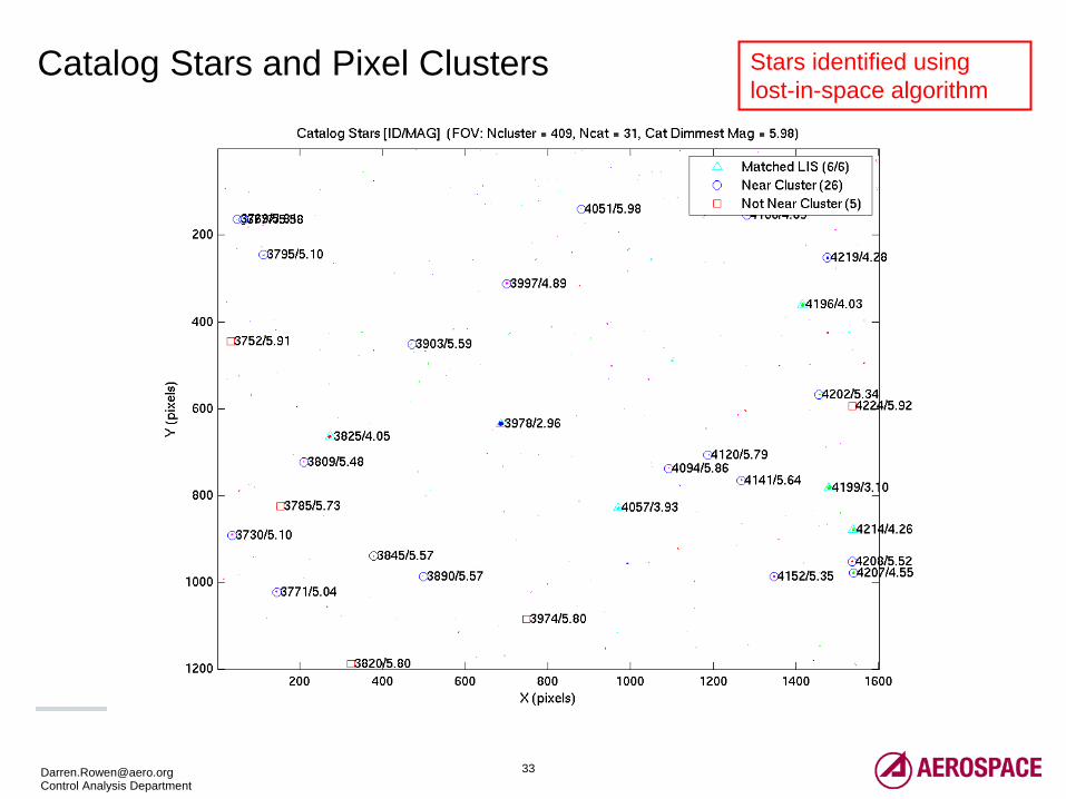
Catalog Stars and Pixel Clusters Stars identified using lost-in-space algorithm
34 [email protected] Control Analysis Department
Conclusions
• Successful 3-axis attitude determination and control – Nadir pointing – Sweep across off-nadir ground target – Track ground target – Inertial pointing
• COTS Camera Photos Very Valuable
– Sensor alignment / calibration – Pointing performance verification – Attitude determination (post-processing on ground)
All trademarks, service marks, and trade names are the property of their respective owners

© The Aerospace Corporation 2013
Thank you