Embed Size (px)
Citation preview
Chapter 3 1
3
Modules, Hierarchy Charts, and Documentation
Programming Logic and Design, Second Edition, Comprehensive
3

Chapter 3 2
3
Objectives
• After studying Chapter 3, you should be able to:
• Describe the advantages of modularization
• Modularize a program
• Understand how a module can call another module
• Explain how to declare variables
Chapter 3 3
3
Objectives
• After studying Chapter 3, you should be able to:
• Create hierarchy charts
• Understand documentation
• Create print charts
• Interpret file descriptions
• Understand the attributes of complete documentation
Chapter 3 4
3
Modules
• Large programs are never written as one huge series of steps.
• Programs are broken down into units called modules.
• Modules are also referred to as:
– subroutines
– functions
– procedures
– methods
Chapter 3 5
3
AdvantagesModularization Allows:
Multiple Programmers to Work on a Problem
1. Dissect large task into modules
2. divide the task among various people
•
Chapter 3 6
3Modularization Allows:
You to Reuse Your Work
• REUSE YOUR WORK
• You can find many real-world examples of reusability
Chapter 3 7
3Modularization :
• When you combine several programming tasks into modules, it may be easier for you to identify structures
Makes It Easier to Identify Structures
Chapter 3 8
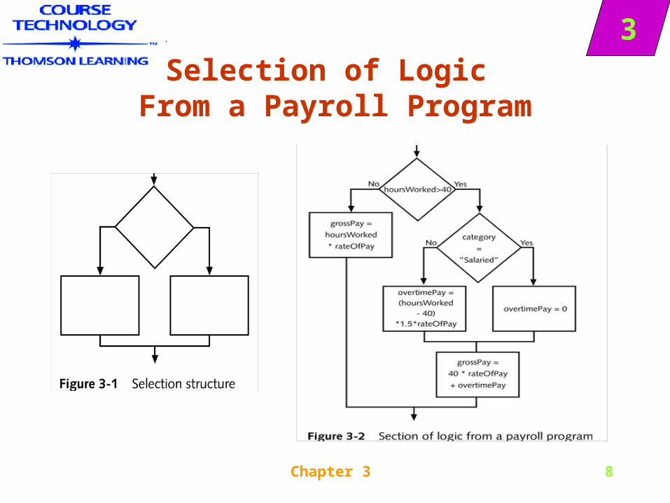
3Selection of Logic
From a Payroll Program
Chapter 3 9
3
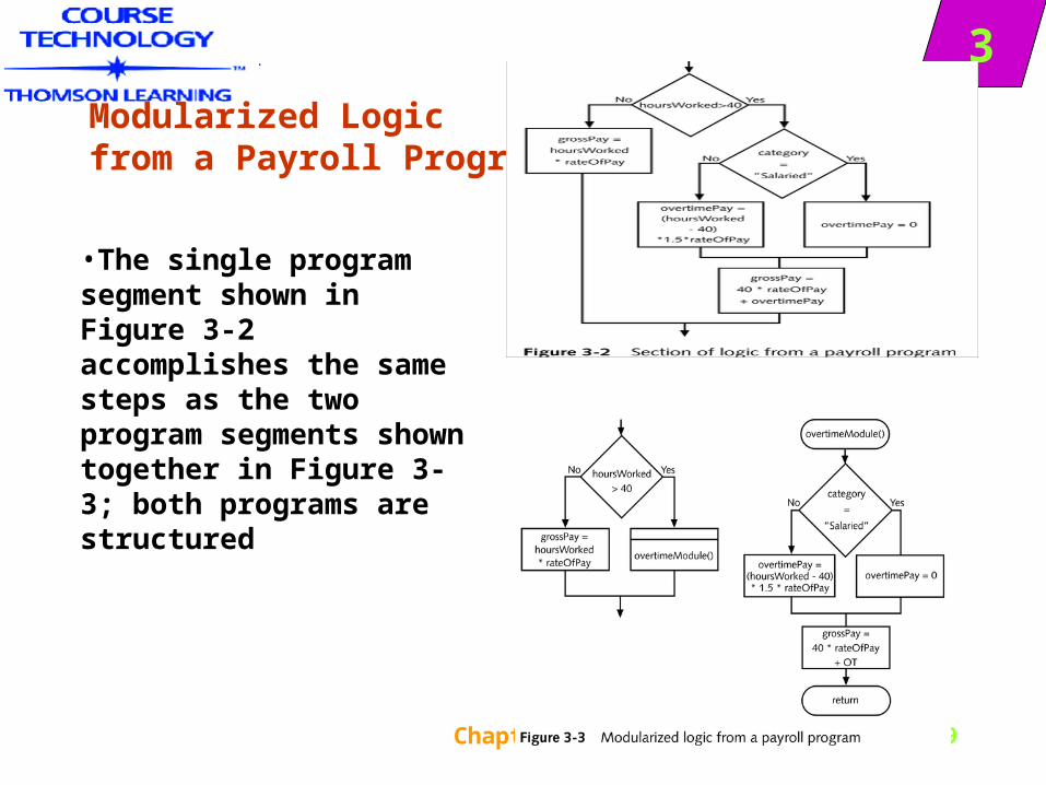
Modularized Logic from a Payroll Program
•The single program segment shown in Figure 3-2 accomplishes the same steps as the two program segments shown together in Figure 3-3; both programs are structured
Chapter 3 10
3
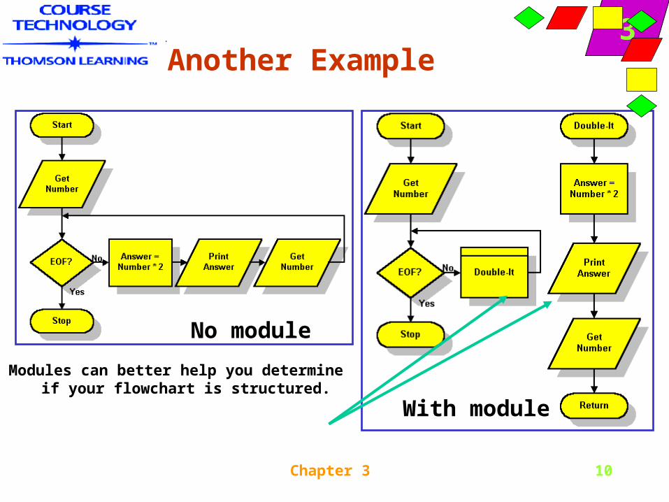
With module
Another Example
Modules can better help you determine if your flowchart is structured.
No module
Chapter 3 11
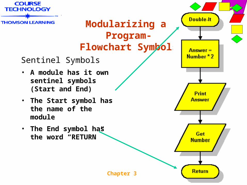
3Modularizing a
Program- Flowchart Symbols
Sentinel Symbols
• A module has it own sentinel symbols (Start and End)
• The Start symbol has the name of the module
• The End symbol has the word “RETURN”
Chapter 3 12
3Modularize a Program:
Naming the MODULE
• In this text, module names will follow the same two rules used for variable names:
– Module names must be one word
– Module names should have some meaning
– Additionally, in this text module names will be followed by a set of parentheses
Chapter 3 13
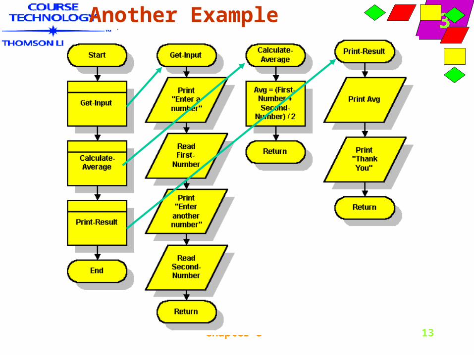
3Another Example
Chapter 3 14
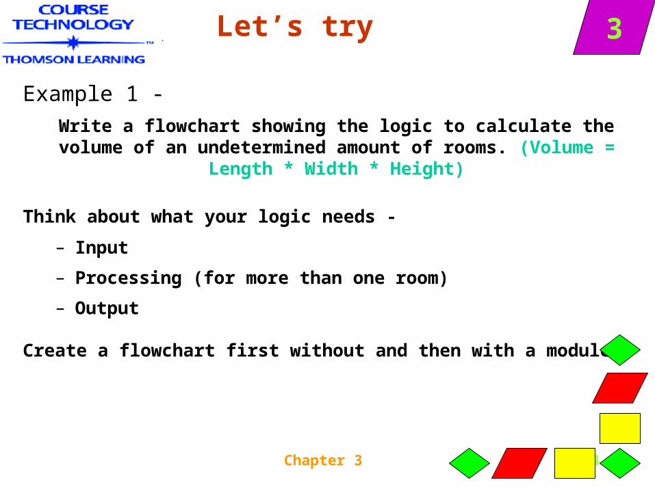
3Let’s try
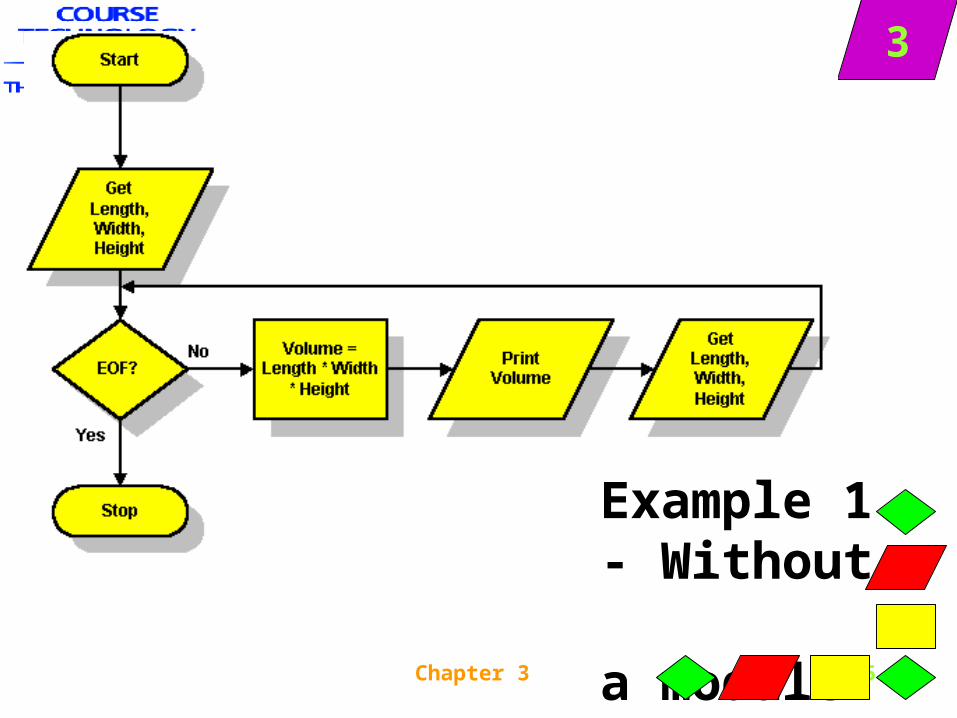
Example 1 -
Write a flowchart showing the logic to calculate the volume of an undetermined amount of rooms. (Volume = Length * Width *
Height)
Think about what your logic needs -
– Input
– Processing (for more than one room)
– Output
Create a flowchart first without and then with a module.
Chapter 3 15
3
Example 1 - Without a module
Chapter 3 16
3
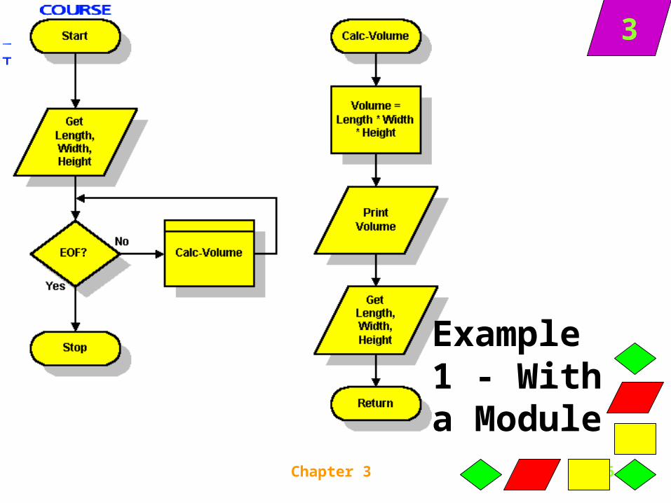
Example 1 - With a Module
Chapter 3 20
3
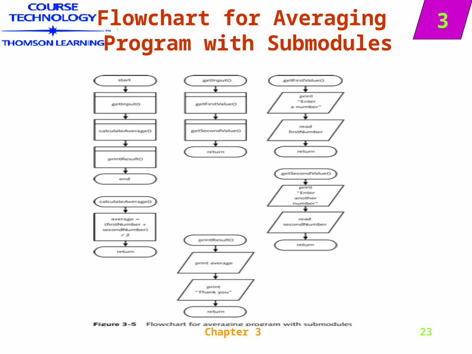
Modules Calling Other Modules
• A module can be called by both the main program or by another module
• Modules called by other modules are called submodules.
Chapter 3 22
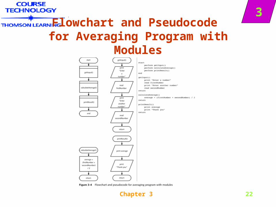
3Flowchart and Pseudocode
for Averaging Program with Modules
Chapter 3 23
3Flowchart for Averaging Program with Submodules
Chapter 3 24
3 Another Tool:
Creating Hierarchy Charts
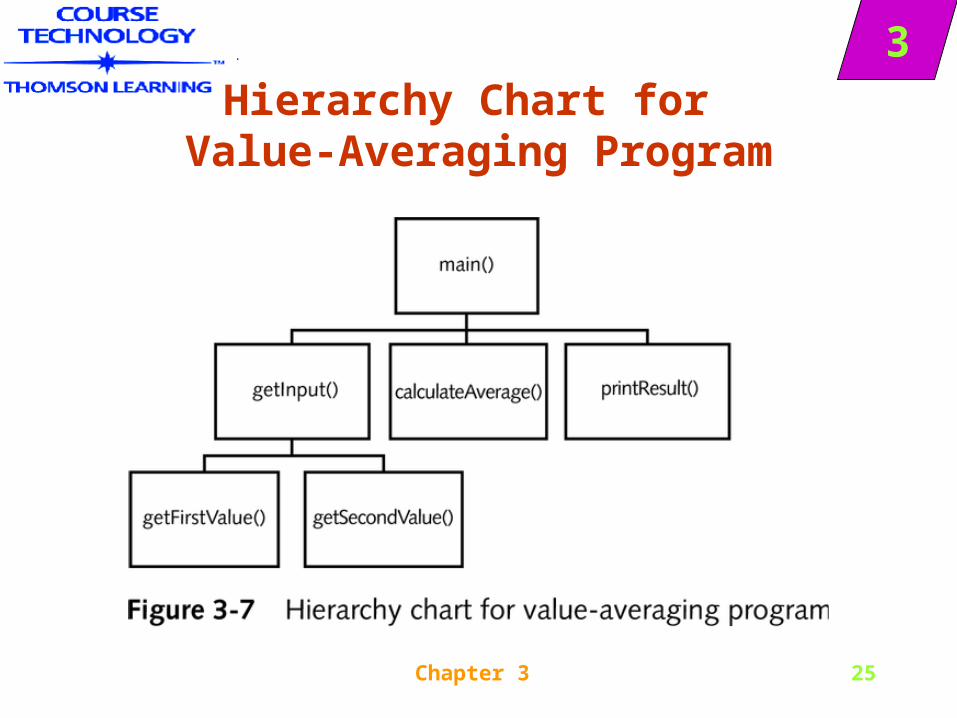
• You can use a hierarchy chart to illustrate modules’ relationships
• A hierarchy chart does not tell you what tasks are to be performed within a module; it does not tell you when or how a module executes
• The hierarchy chart for the last version of the value-averaging program looks like Figure 3-7
Chapter 3 25
3Hierarchy Chart for
Value-Averaging Program
Chapter 3 26
3
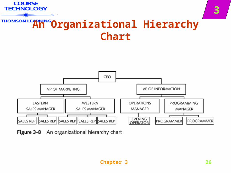
An Organizational Hierarchy Chart
Chapter 3 27
3
Declaring Variables
• Declaring a variable provides a name for a memory location
– where computer stores variable values
– notifies computer of data type
• Programming languages declare variables differently, but minimally you must
– give the variable a name
– give the variable a data type
Chapter 3 28
3
Declaring Variables
• An annotation symbol or annotation box is simply an attached box containing notes
• You can use an annotation symbol any time you have more to write than conveniently fits within a flowchart symbol
• Programmers sometimes create a data dictionary, which is a list of every variable name used in a program, along with its type, size, and description
• When a data dictionary is created, it becomes part of the program documentation
Chapter 3 29
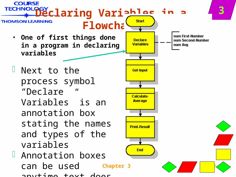
3Declaring Variables in a Flowchart
• One of first things done in a program in declaring variables
Next to the process symbol “Declare Variables” is an annotation box stating the names and types of the variables
Annotation boxes can be used anytime text does not fit in a symbol
Chapter 3 30
3
Declaring Variables
• Languages including COBOL, C++, C#, Java, and Pascal require declaration of variables with name and type
• Modern programming languages: variables are declared within each module that uses them. Such variables are known as local variables
• We will use global variables—variables that are given a type and name once- used in all modules of the program
Chapter 3 31
3
What is Documentation
• All supporting material that goes along with a program– User documentation
• Manuals
• Training material
– Program documentation
• used for planning or modifying programs
• internal and external program documentation
Chapter 3 32
3PROGRAM :
Input Documentation
• A file description describes the data contained in an input file
• File’s description as part of an organization’s information systems’ documentation;
Chapter 3 33
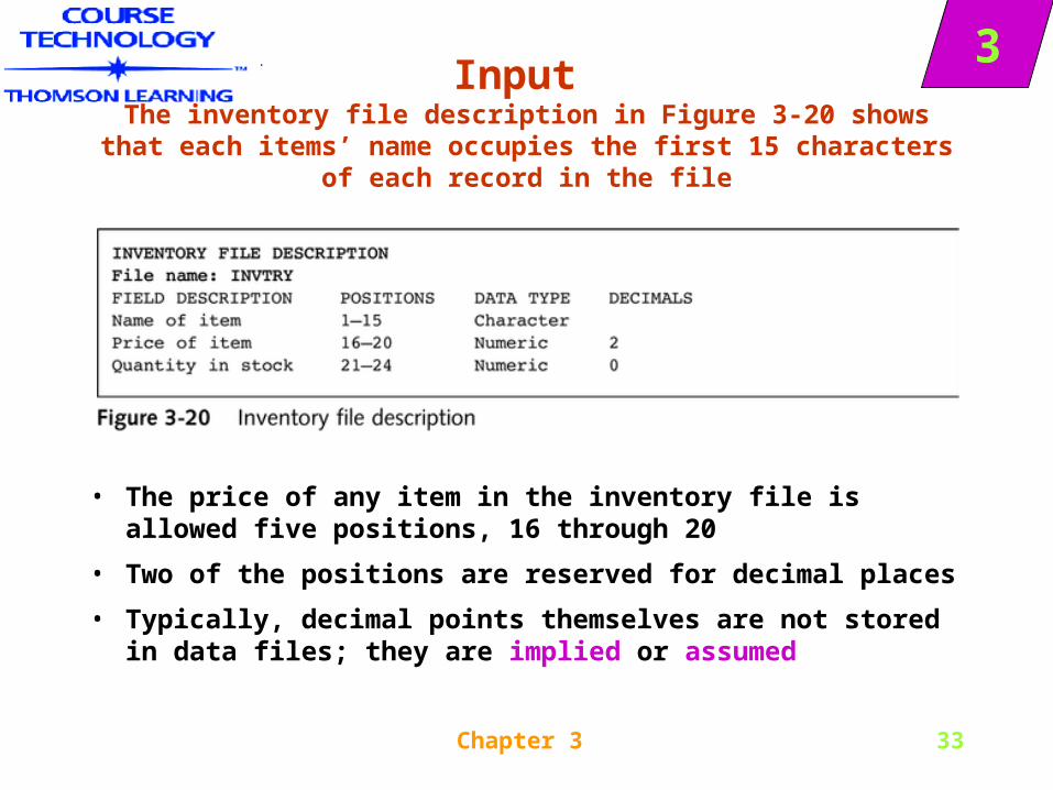
3Input
The inventory file description in Figure 3-20 shows that each items’ name occupies the first 15 characters of each record in the file
• The price of any item in the inventory file is allowed five positions, 16 through 20
• Two of the positions are reserved for decimal places
• Typically, decimal points themselves are not stored in data files; they are implied or assumed
Chapter 3 34
3
Input Documentation
• Numeric data are stored with leading zeros
• Programmers create one variable for each field in the input file
Chapter 3 35
3
Input Documentation
• Recall the data hierarchy relationship introduced in Chapter 1:
– Database
– File
– Record
– Field
– Character
Chapter 3 36
3
Input Documentation
• The programmer needs to know is:
– What is the name of the file?
– What data does it contain?
– How much room does the file and each of its fields take up?
– What type of data is each field—character or numeric?
Chapter 3 37
3
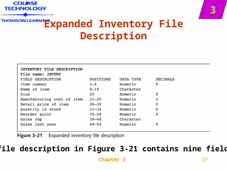
Expanded Inventory File Description
•The file description in Figure 3-21 contains nine fields
Chapter 3 38
3Internal Documentation
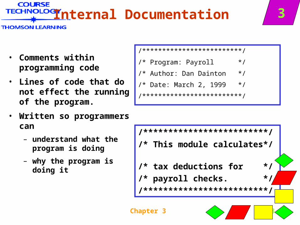
• Comments within programming code
• Lines of code that do not effect the running of the program.
• Written so programmers can
– understand what the program is doing
– why the program is doing it
/*************************/
/* Program: Payroll */
/* Author: Dan Dainton */
/* Date: March 2, 1999 */
/*************************/
/*************************/
/* This module calculates*/
/* tax deductions for */
/* payroll checks. */
/*************************/
Chapter 3 39
3External Documentation
• All supporting paperwork a programmer develops before writing a program.
• External documentation can describe
– Input
– Processing
– Output
• Output documentation is developed first. Why?
Chapter 3 40
3
Output Documentation
• Generally, the reason you would write a program in a business environment is because particular information is needed.
• Can the programmer decide what information is needed and how it’s designed? Can the user requesting the information?
Chapter 3 41
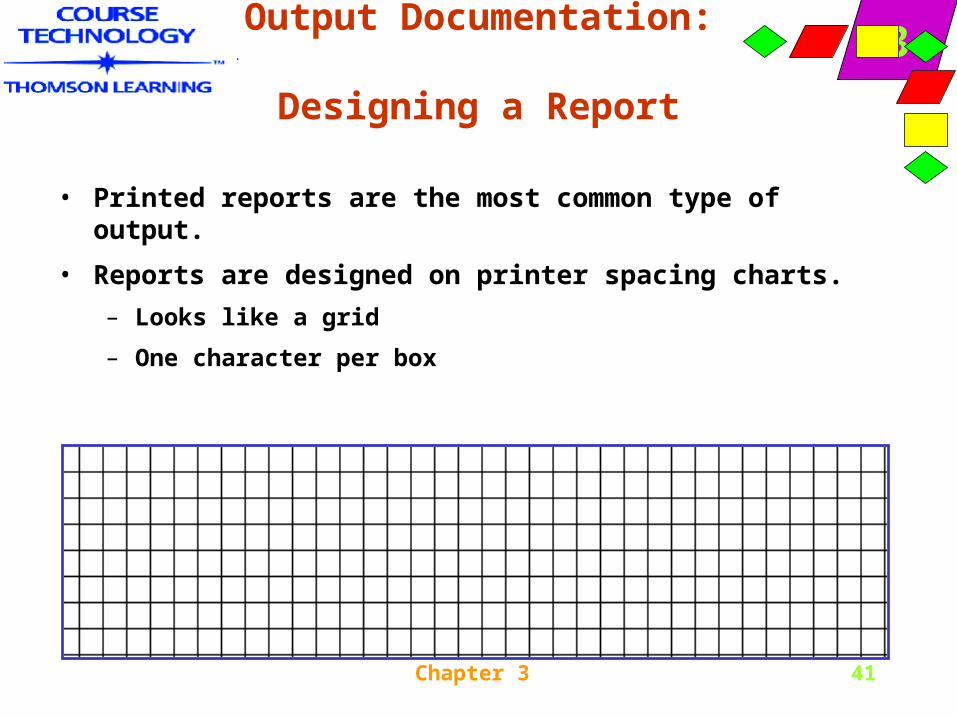
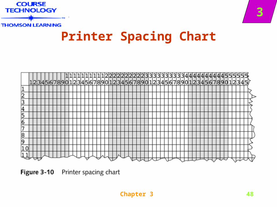
3Output Documentation:
Designing a Report
• Printed reports are the most common type of output.
• Reports are designed on printer spacing charts.
– Looks like a grid
– One character per box
Chapter 3 42
3
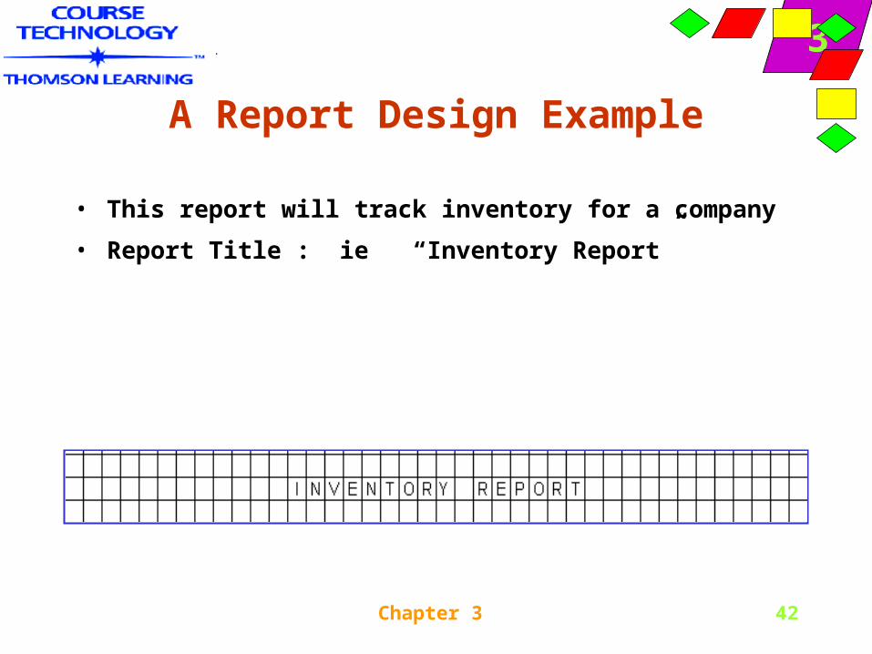
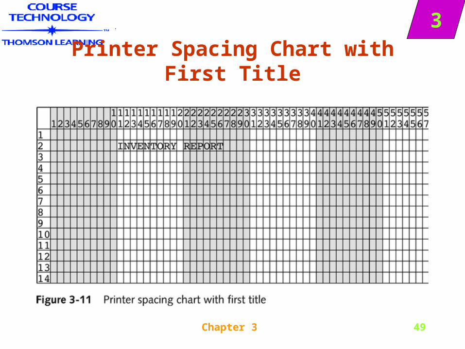
A Report Design Example
• This report will track inventory for a company
• Report Title : ie “Inventory Report”
Chapter 3 43
3
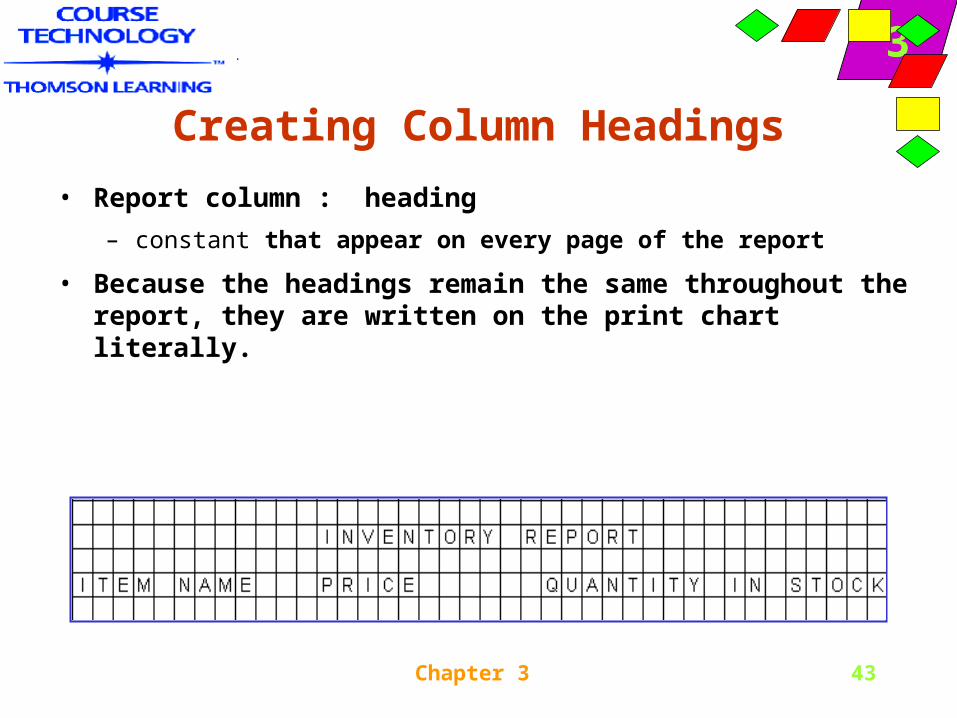
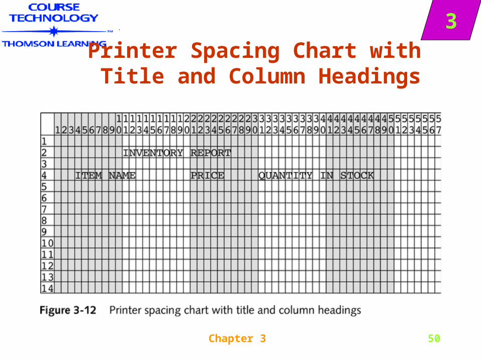
Creating Column Headings
• Report column : heading
– constant that appear on every page of the report
• Because the headings remain the same throughout the report, they are written on the print chart literally.
Chapter 3 44
3
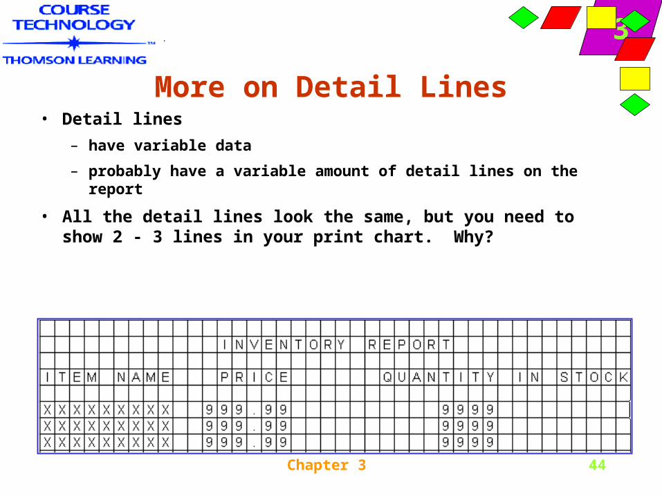
More on Detail Lines• Detail lines
– have variable data
– probably have a variable amount of detail lines on the report
• All the detail lines look the same, but you need to show 2 - 3 lines in your print chart. Why?
Chapter 3 45
3
Understanding Documentation
• Documentation refers to all of the supporting material that goes with a program
• Two broad categories of documentation are intended for the programmer and for the user
• People who use computer programs are called end users, or users for short
• When programmers begin to plan the logic of a computer program, they require instructions known as program documentation
Chapter 3 46
3
Understanding Documentation
• Program documentation falls into two categories: internal and external
• Internal program documentation consists of program comments, or nonexecuting statements that programmers place within their code to explain program statements in English
• External program documentation includes all the supporting paperwork that programmers develop before they write a program

Chapter 3 47
3
Output Documentation
• Output documentation is usually the first to be written
• The most common type of output is a printed report
• You can design a printed report on a printer spacing chart, which is also referred to as a print chart or a print layout
• The title and column headings will be constant on every page of the report so they are written on the print chart literally
Chapter 3 48
3
Printer Spacing Chart
Chapter 3 49
3
Printer Spacing Chart with First Title
Chapter 3 50
3Printer Spacing Chart with Title and Column Headings
Chapter 3 51
3
Output Documentation
• The exact spacing and use of upper- or lowercase make a difference
• Notice that the constants used within a report do not need to follow the same rules as variable names
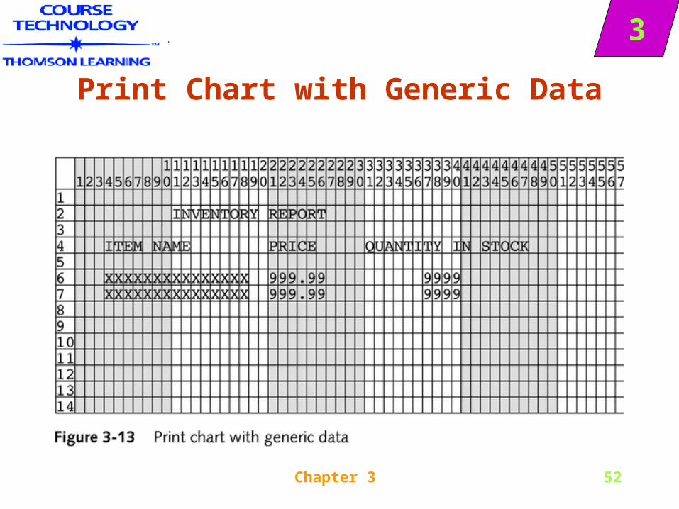
• A print layout typically shows how the variable data will appear on the report
• Each line with its Xs and 9s representing data is a detail line because it contains the data details
Chapter 3 52
3
Print Chart with Generic Data
Chapter 3 53
3
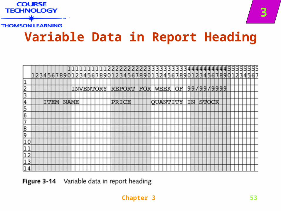
Variable Data in Report Heading

Chapter 3 54
3
Heading with Page Numbers
Chapter 3 55
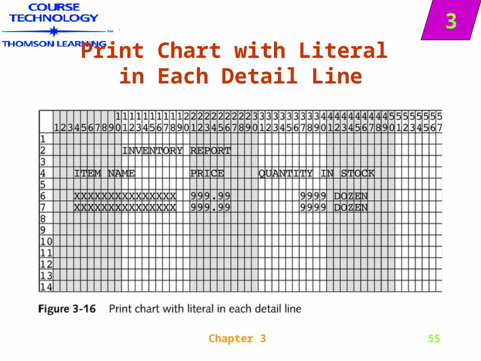
3Print Chart with Literal
in Each Detail Line
Chapter 3 56
3
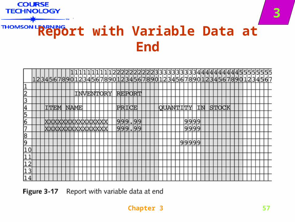
Output Documentation
• Detail lines typically appear many times per page, as opposed to heading lines, which usually appear only once per page
• Besides header lines and detail lines, reports often include special lines at the end of a report
• Even though lines at the end of a report don’t always contain numeric totals, they are usually referred to generically as total lines
Chapter 3 57
3
Report with Variable Data at End
Chapter 3 58
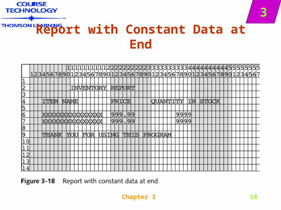
3
Report with Constant Data at End
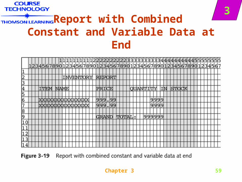
Chapter 3 59
3Report with Combined
Constant and Variable Data at End
Chapter 3 60
3
Completing the Documentation• Program Documentation
– Design outputPlan the logic of the program
– Code the program
– Test the program
• User documentation
– User documentation instructional materials that nontechnical people use
Chapter 3 61
3
Completing the Documentation
• The areas addressed in user documentation may include:
– Description of input for the program
– Who needs the output
– What output should look like
– How to interpret and react to any error message generated by the program
– How frequently the program needs to run
Chapter 3 62
3IN Summary-
Review Modules
• Programming using modules
• Module is given a name- that name is CALLED by the calling program
• A module can call other modules
Chapter 3 63
3
Summary- Variables
• To Declaring a Variable: providing a name for the memory location where the value is stored
• Identify the data type You can use a hierarchy chart to illustrate modules’ relationships
• Documentation refers to all of the supporting material that goes with a program
• Output documentation is usually written first
Chapter 3 64
3
Summary- Documentation
• File description: lists the data in a file ( description, size, and data type)
• Program documentation – file descriptions, printer spacing charts etc
• User Documentation manuals or other instructional materials that nontechnical people use as well as the operating instructions that computer operators and data-entry personnel may need