Embed Size (px)
Citation preview
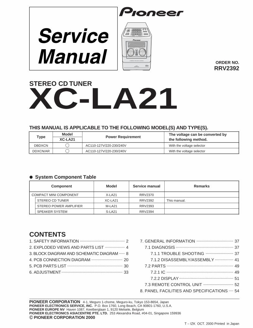
ORDER NO.
PIONEER CORPORATION 4-1, Meguro 1-chome, Meguro-ku, Tokyo 153-8654, JapanPIONEER ELECTRONICS SERVICE, INC. P.O. Box 1760, Long Beach, CA 90801-1760, U.S.A.PIONEER EUROPE NV Haven 1087, Keetberglaan 1, 9120 Melsele, BelgiumPIONEER ELECTRONICS ASIACENTRE PTE. LTD. 253 Alexandra Road, #04-01, Singapore 159936 PIONEER CORPORATION 2000c
XC-LA21RRV2392
T – IZK OCT. 2000 Printed in Japan
STEREO CD TUNER
1. SAFETY INFORMATION ....................................... 2
2. EXPLODED VIEWS AND PARTS LIST ................. 4
3. BLOCK DIAGRAM AND SCHEMATIC DIAGRAM ..... 8
4. PCB CONNECTION DIAGRAM ........................... 20
5. PCB PARTS LIST ................................................ 30
6. ADJUSTMENT..................................................... 33
CONTENTS7. GENERAL INFORMATION ................................ 37
7.1 DIAGNOSIS .................................................. 37
7.1.1 TROUBLE SHOOTING ........................ 37
7.1.2 DISASSEMBLY/ASSEMBLY ................ 41
7.2 PARTS .......................................................... 49
7.2.1 IC .......................................................... 49
7.2.2 DISPLAY............................................... 51
7.3 REMOTE CONTROL UNIT .......................... 52
8. PANEL FACILITIES AND SPECIFICATIONS .... 54
THIS MANUAL IS APPLICABLE TO THE FOLLOWING MODEL(S) AND TYPE(S).
Component Model Service manual Remarks
COMPACT MINI COMPONENT X-LA21 RRV2370
STEREO CD TUNER XC-LA21 RRV2392 This manual.
STEREO POWER AMPLIFIER M-LA21 RRV2393
SPEAKER SYSTEM S-LA21 RRV2394
¶ System Component Table
LA21
3 COMPACT DISC MULTI CHANGER
STEREO CD TUNER
TypeModel
Power RequirementThe voltage can be converted by
XC-LA21 the following method.
DBDXCN AC110-127V/220-230/240V With the voltage selector
DDXCN/AR AC110-127V/220-230/240V With the voltage selector
XC-LA21
2
Additional Laser Caution
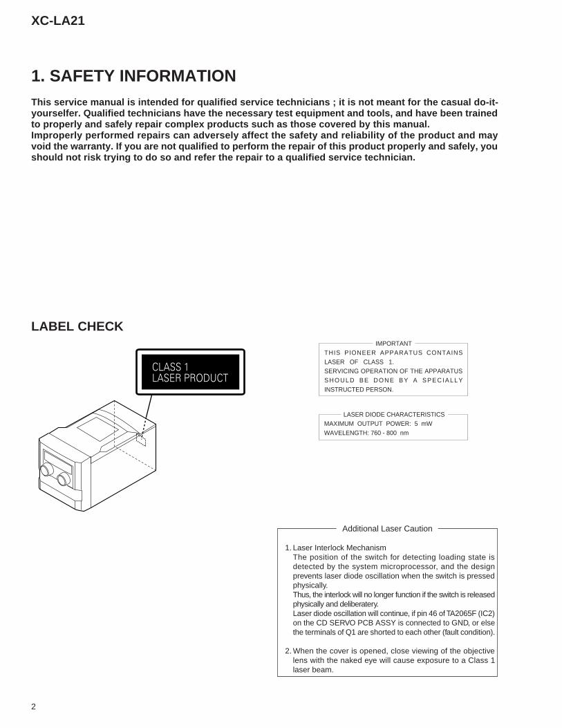
1. Laser Interlock MechanismThe position of the switch for detecting loading state isdetected by the system microprocessor, and the designprevents laser diode oscillation when the switch is pressedphysically.Thus, the interlock will no longer function if the switch is releasedphysically and deliberatery.Laser diode oscillation will continue, if pin 46 of TA2065F (IC2)on the CD SERVO PCB ASSY is connected to GND, or elsethe terminals of Q1 are shorted to each other (fault condition).
2. When the cover is opened, close viewing of the objectivelens with the naked eye will cause exposure to a Class 1laser beam.
LASER DIODE CHARACTERISTICSMAXIMUM OUTPUT POWER: 5 mWWAVELENGTH: 760 - 800 nm
IMPORTANTTHIS PIONEER APPARATUS CONTAINSLASER OF CLASS 1.SERVICING OPERATION OF THE APPARATUSSHOULD BE DONE BY A SPECIALLYINSTRUCTED PERSON.
LABEL CHECK
1. SAFETY INFORMATIONThis service manual is intended for qualified service technicians ; it is not meant for the casual do-it-yourselfer. Qualified technicians have the necessary test equipment and tools, and have been trainedto properly and safely repair complex products such as those covered by this manual.Improperly performed repairs can adversely affect the safety and reliability of the product and mayvoid the warranty. If you are not qualified to perform the repair of this product properly and safely, youshould not risk trying to do so and refer the repair to a qualified service technician.
3
XC-LA21
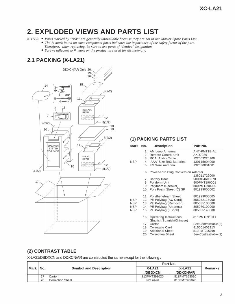
2.1 PACKING (X-LA21)
2. EXPLODED VIEWS AND PARTS LISTNOTES: • Parts marked by "NSP" are generally unavailable because they are not in our Master Spare Parts List.
• The mark found on some component parts indicates the importance of the safety factor of the part. Therefore, when replacing, be sure to use parts of identical designation.
• Screws adjacent to mark on the product are used for disassembly.
SYSTEMSPEAKER
REARXC-LA21
REARM-LA21
FRONT
FRONT
FRONT
FRONT
TOP SIDETOP SIDE
13
3
15
14
7
411
17
15
161920DDXCN/AR Only
9(2/2)
10
10
9(1/2)
8(2/2)
128(1/2)
1818
11
8(2/2)
12
128(1/2)
6
2
(1) PACKING PARTS LISTMark No. Description Part No.
1 AM Loop Antenna ANT-PMT1E-AL2 Remote Control Unit AXD72893 RCA Audio Cable 122003220100
NSP 4 ‘AAA’ Size R03 Batteries 1301150040005 FM Wire Antenna 132030001001
6 Power-cord Plug Conversion Adaptor138011722000
7 Battery Door 500RC46030708 Polyform Unit 800PMT1900019 Polyfoam (Speaker) 800PMT390000
10 Poly Foam Sheet (C) SP 801999000002
11 Polythenefoam Sheet 801999000005NSP 12 PE Polybag (AC Cord) 805032115000NSP 13 PE Polybag (Remocon) 805035105000NSP 14 PE Polybag (Antenna) 805070100000NSP 15 PE Polybag (I Book) 805085140000
16 Operating Instructions 811PMT391011(English/Spanish/Chinese)
17 Carton See Contrast table (2)18 Corrugate Card 81500140521319 Additional Sheet 810PMT39501020 Correction Sheet See Contrast table (2)
(2) CONTRAST TABLEX-LA21/DBDXCN and DDXCN/AR are constructed the same except for the following :
Part No.Mark No. Symbol and Description X-LA21 X-LA21 Remarks
/DBDXCN /DDXCN/AR17 Carton 813PMT393020 813PMT39301020 Correction Sheet Not used 810PMT395020
4
XC-LA21
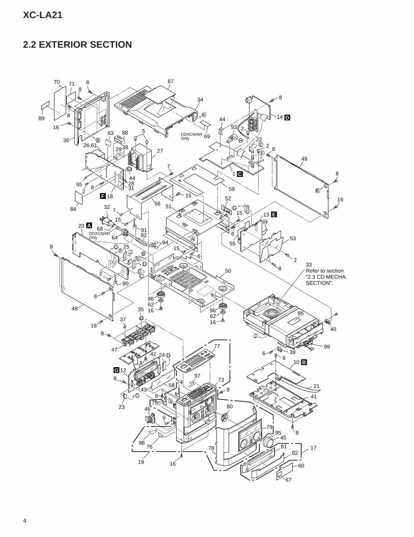
2.2 EXTERIOR SECTION
GF
EBJ
D
C
D
CA
H
G
E
F
K
K
H
A
B
J
8
34
8771
5
27
7
2
7
15
64
32
20
8
442831
8
56
15
51
59
1
82
2
8
14
49
8
16
53
2
8
13
6
15
50
62
15
6
2
8
16
48 35
37
8
47
12
858
77
98
75
74
46
76
19 16
9
73
80
45
79
8182
17
60
8
41
10
40
85
52
33Refer to section"2.3 CD MECHA.SECTION".
66 39
18
26,6129
8
8
16
36
70
89
69
65
84
4493
22
55
9192
94
99
21
67
95
97
2442
43
23
8
78
90
25
68
98
38
8863
F
A
GB
E
C
D
16
966216
96
DDXCN/AR Only
DDXCN/AR Only
5
XC-LA21
(1) EXTERIOR SECTION PARTS LISTMark No. Description Part No.
1 AUDIO Assy PMT1010002102 Screw BBZ30P060FMC3 • • • • • •4 • • • • • •5 Screw BBZ40P060FMC
6 Screw BPZ20P050FMC7 Screw BPZ26P080FMC8 Screw BPZ30P100FNI9 Screw CBZ30P060FMC
10 CD Assy CD--PMT1E
11 • • • • • •12 DISPLAY/CTL Assy PMT10100004113 RECT ASSY PMT1LA10006114 AUX Assy PMT1LA10009115 Screw KBZ30P040FMC
16 Screw KBZ30P060FNI17 CD DOOR Assy PMT3CDDR-DB18 TRANS Assy PMT1LA10007119 S-Assy PMT3 FP01 SUBPMT3CDFP20 STD. TUNER Assy TUN-PMT1E-DL
21 FFC Cable 16Pin L100 04016010010122 FFC Cable 16Pin L260 04016026010023 FFC Cable 17Pin L100 04017010010024 FFC Cable 24Pin L200 04024020013025 FFC Cable 30Pin L400 040300400100
26 STANDBY TRANSFORMER 1233D4828140 27 Power TF EI35 11-24V 1231D3513140 28 Micro Fuse 251001 124010010002 29 Fuse (500mA/250V) 124005020002
30 • • • • • •
31 Micro Fuse #25103.5 124035010000 32 AC Cord See Contrast table (2) 33 CD MECHA,CMCJ 153000117000
34 Top Panel 500PMT14800235 Direct Access Knob Lens 500PMT111000
36 Back Cover 500PMT18300037 Power Standby Lens 500PMT12900038 Fuse Insulation Cap 50062320000039 CD Base Adaptor R 503PMT12500040 CD Base Adaptor L 503PMT126000
41 Servo PCB Bracket 505PMT11400042 FL Bracket 505PMT13400043 LED Bracket 505PMT13500044 PCB Mounting Bracket 505PMT13600045 Volume Knob 510PMT328001
46 Clock Control Knob 510PMT10800247 Direct Access Knob Set 510PMT10902048 Side Panel-L 600PMT11700249 Side Panel-R 600PMT118002
NSP 50 Bottom Tray 600PMT121000
51 Transformer Bracket 605PMT12200052 FCC Cable HLD 605PMT14200053 Cable Holder 605PMT14300054 • • • • • •55 Heat Sink 613PMT131000
56 CD Shield Plate 650PMT13900057 • • • • • •58 Display Filter Plate 650PMT14700259 PC Sheet 650PMT14900060 Transport Stopper PL 650PMT197010
61 Shielding Plate 65027722500062 Rubber Foot 700PMT38400063 Capacitor Boot 700PMT15000064 Bushing 700PMT15600065 Cable/Plastic Tie 727000100000
66 • • • • • •NSP 67 Trans. Stopper Label 809PMT194021
68 AC Cord Label See Contrast table (2)69 Voltage Label See Contrast table (2)70 Warning Label See Contrast table (2)
71 Back Label See Contrast table (2)72 • • • • • •
NSP 73 Front Panel 500PMT101002NSP 74 GND. Copper Plate C 650PMT152000NSP 75 GND. Copper Plate D 650PMT153000
NSP 76 GND. Copper Plate E 650PMT155000NSP 77 Control Panel Plate 650PMT116020NSP 78 Front Cover 600PMT160010NSP 79 Display Lens 500PMT106020NSP 80 Illuminated Ring 509PMT105000
NSP 81 CD Door 500PMT102002NSP 82 CD Door Cover 600PMT120020
83 • • • • • •84 PCB Insulation Sheet 650PMT15700085 CD Caution Label See Contrast table (2)
86 • • • • • •87 Voltage Sel. Cover 500PMT11000288 Voltage Sel. Knob 510PMT112002
NSP 89 Serial Label 80900000900090 Tube AWG5 D4.72 L70 728000047L07
91 Tube AWG5 D4.72 L90 728000047L0992 Tube AWG1 D7.35 L120 728000073L1293 Tube AWG1 D7.35 L160 728000073L1694 Tube AWG1 D7.35 L15 728000073L1595 Volume Chrome Ring 509PMT330001
96 Foot Stand 509PMT329000NSP 97 GND. Copper Plate A 650PMT140000NSP 98 GND. Copper Plate B 650PMT141000
99 Ferrite Core 032219180000
Mark No. Description Part No.
(2) CONTRAST TABLEXC-LA21/DBDXCN and DDXCN/AR are constructed the same except for the following :
Part No.Mark No. Symbol and Description XC-LA21 XC-LA21 Remarks
/DBDXCN /DDXCN/AR32 AC Cord 134250220000 13422012001668 AC Cord Label Not used 809PMT39410069 Voltage Label Not used 809PMT39408070 Warning Label 809PMT396110 809PMT39401071 Back Label 809PMT396030 809PMT396050
85 CD Caution Label 809PMT194070 809PMT394090
6
XC-LA21
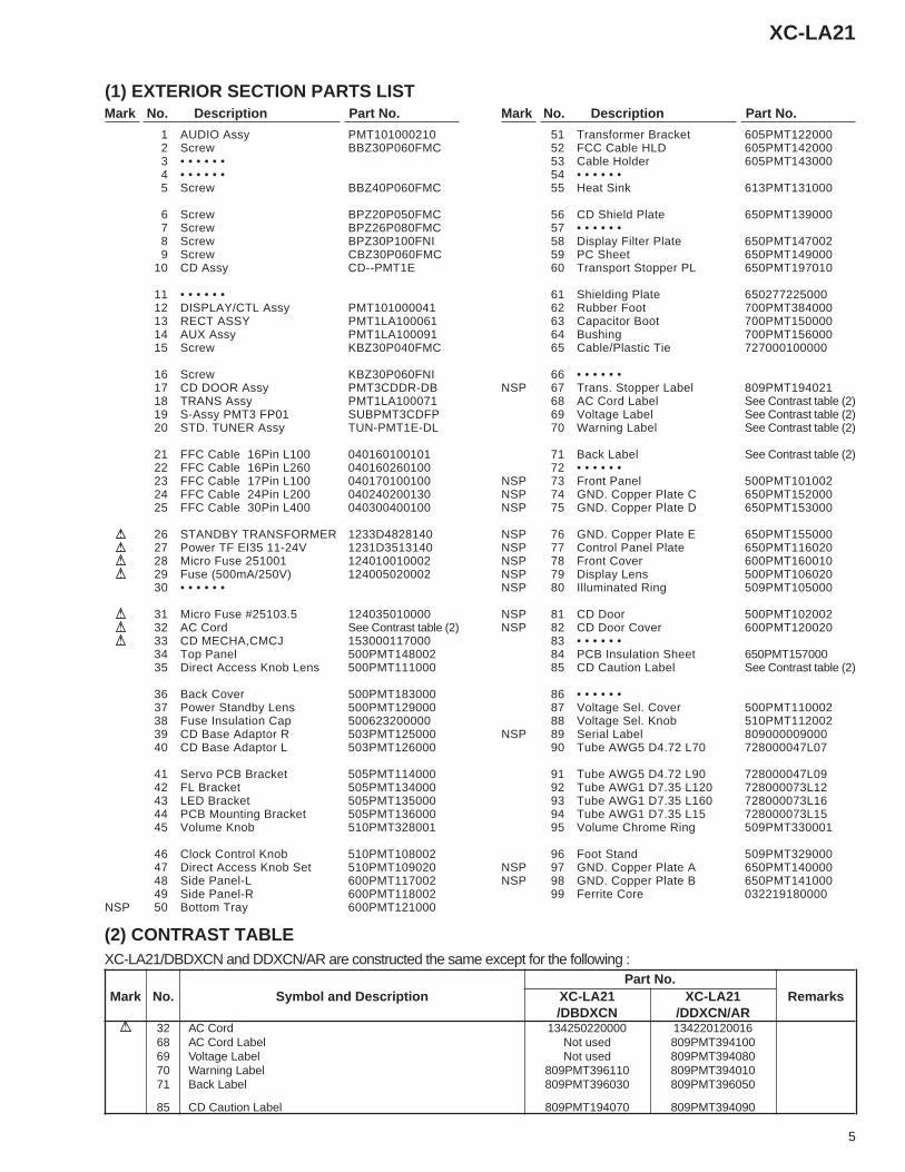
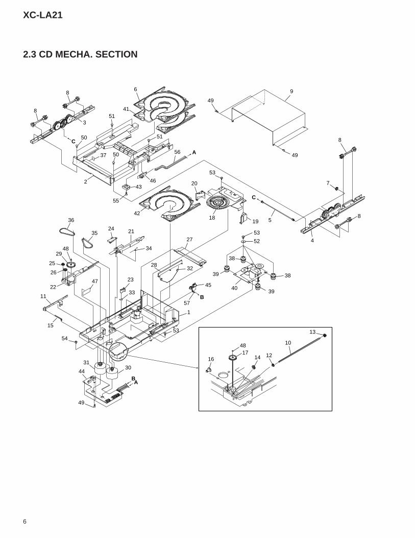
2.3 CD MECHA. SECTION
C
A
C
B
BA
8
8
351
6
41
51
565037
50
243
46
55
42
20
53
1819
49
9
49
8
7
58
453
52
38
3940
39
38
27
45
212435
36
4829
25
26
2247
11
15
54
23
33
32
57
28
1
53
3031
44
49
16
4817
14 12
10
13
34
7
XC-LA21
Mark No. Description Part No.
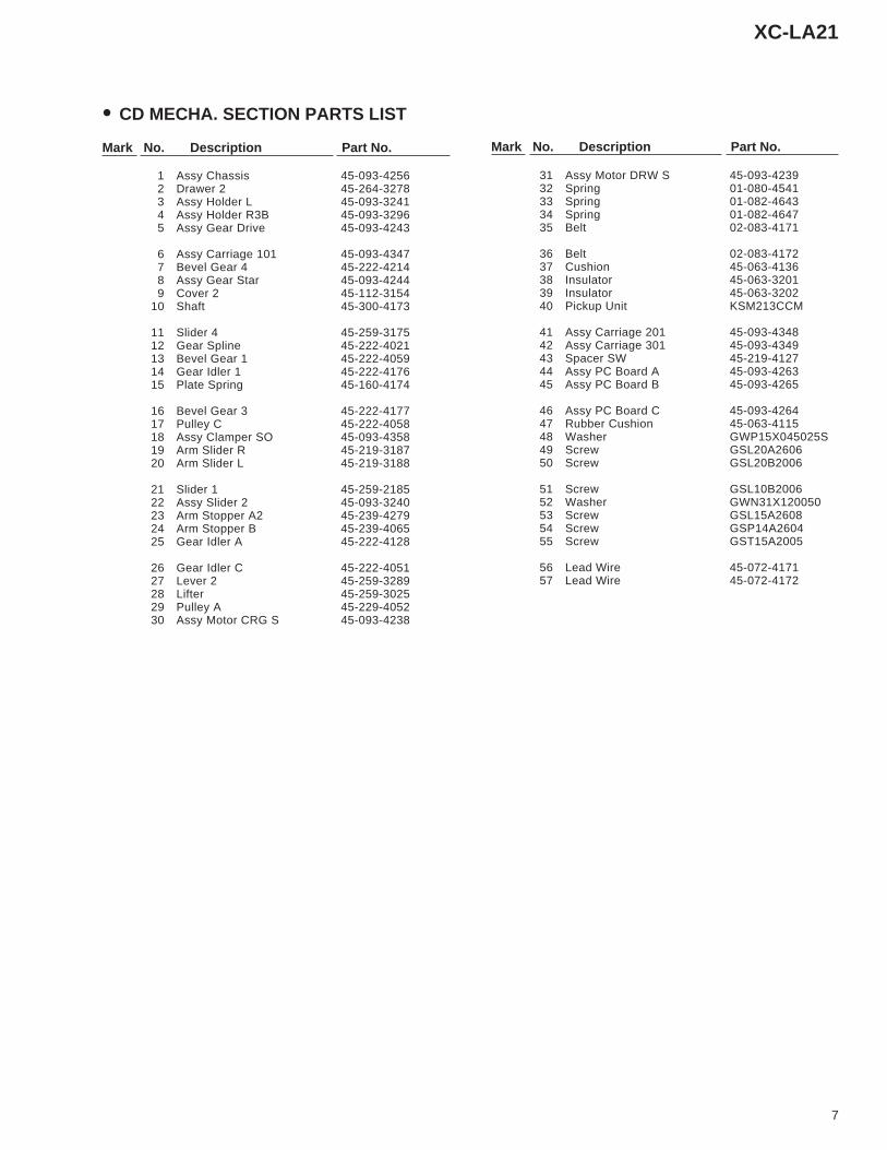
• CD MECHA. SECTION PARTS LIST
Mark No. Description Part No.
1 Assy Chassis 45-093-42562 Drawer 2 45-264-32783 Assy Holder L 45-093-32414 Assy Holder R3B 45-093-32965 Assy Gear Drive 45-093-4243
6 Assy Carriage 101 45-093-43477 Bevel Gear 4 45-222-42148 Assy Gear Star 45-093-42449 Cover 2 45-112-3154
10 Shaft 45-300-4173
11 Slider 4 45-259-317512 Gear Spline 45-222-402113 Bevel Gear 1 45-222-405914 Gear Idler 1 45-222-417615 Plate Spring 45-160-4174
16 Bevel Gear 3 45-222-417717 Pulley C 45-222-405818 Assy Clamper SO 45-093-435819 Arm Slider R 45-219-318720 Arm Slider L 45-219-3188
21 Slider 1 45-259-218522 Assy Slider 2 45-093-324023 Arm Stopper A2 45-239-427924 Arm Stopper B 45-239-406525 Gear Idler A 45-222-4128
26 Gear Idler C 45-222-405127 Lever 2 45-259-328928 Lifter 45-259-302529 Pulley A 45-229-405230 Assy Motor CRG S 45-093-4238
31 Assy Motor DRW S 45-093-423932 Spring 01-080-454133 Spring 01-082-464334 Spring 01-082-464735 Belt 02-083-4171
36 Belt 02-083-417237 Cushion 45-063-413638 Insulator 45-063-320139 Insulator 45-063-320240 Pickup Unit KSM213CCM
41 Assy Carriage 201 45-093-434842 Assy Carriage 301 45-093-434943 Spacer SW 45-219-412744 Assy PC Board A 45-093-426345 Assy PC Board B 45-093-4265
46 Assy PC Board C 45-093-426447 Rubber Cushion 45-063-411548 Washer GWP15X045025S49 Screw GSL20A260650 Screw GSL20B2006
51 Screw GSL10B200652 Washer GWN31X12005053 Screw GSL15A260854 Screw GSP14A260455 Screw GST15A2005
56 Lead Wire 45-072-417157 Lead Wire 45-072-4172
XC-LA21
8
A
B
C
D
1 2 3 4
1 2 3 4
10 10
27
28
29
30
CN3(16P)
CN4(6P)
CN101
CN102
CN6(30P)
CN8(30P)
CN401(24P)
CN205(24P)
CN404(17P)
CN207(17P)
CN5
CONTROL DATA
CN402
SpindleMotor
PICKUPASSY
CD MECHA.
(16P)
B CD ASSY
G DISPLAY/CTL ASSY
A STD. TUNER ASSY
4
CarriageMotor
DrawerMotor
AM
FM
ANTENNA
+
-
+
-
321
1
2CA
RR
+F
IN
RFO RFI
CD-L
+9V
CD-R
CA
RR
-
DR
AW
-
DR
AW
+
IC2TA2065FRF AMP.
IC1TC9284BFDECODER
IC401PDA068A
SYSTEM CONTROL IC
LCD401FL TUBE
IC4BA4558N
IC6TA7291SDRIVER
IC3TA2092NDRIVER
1LO 6RO 2
532
7 3
IC7TA7291SDRIVER
7 3
FE101
T101 T103
1 8
9 1 9 1
27
28
29
30
73-76
VOLJOG
KEY INPUT
M M
617
RIN
FIN
RIN
5V
12 12-24V
14 14
3V8
15 15
P8V
17 17
3V8
+9V
8-10 8-10
12-1512-15
FUNCTIONJOG
(FM)
(AM)
(FM)
(AM)
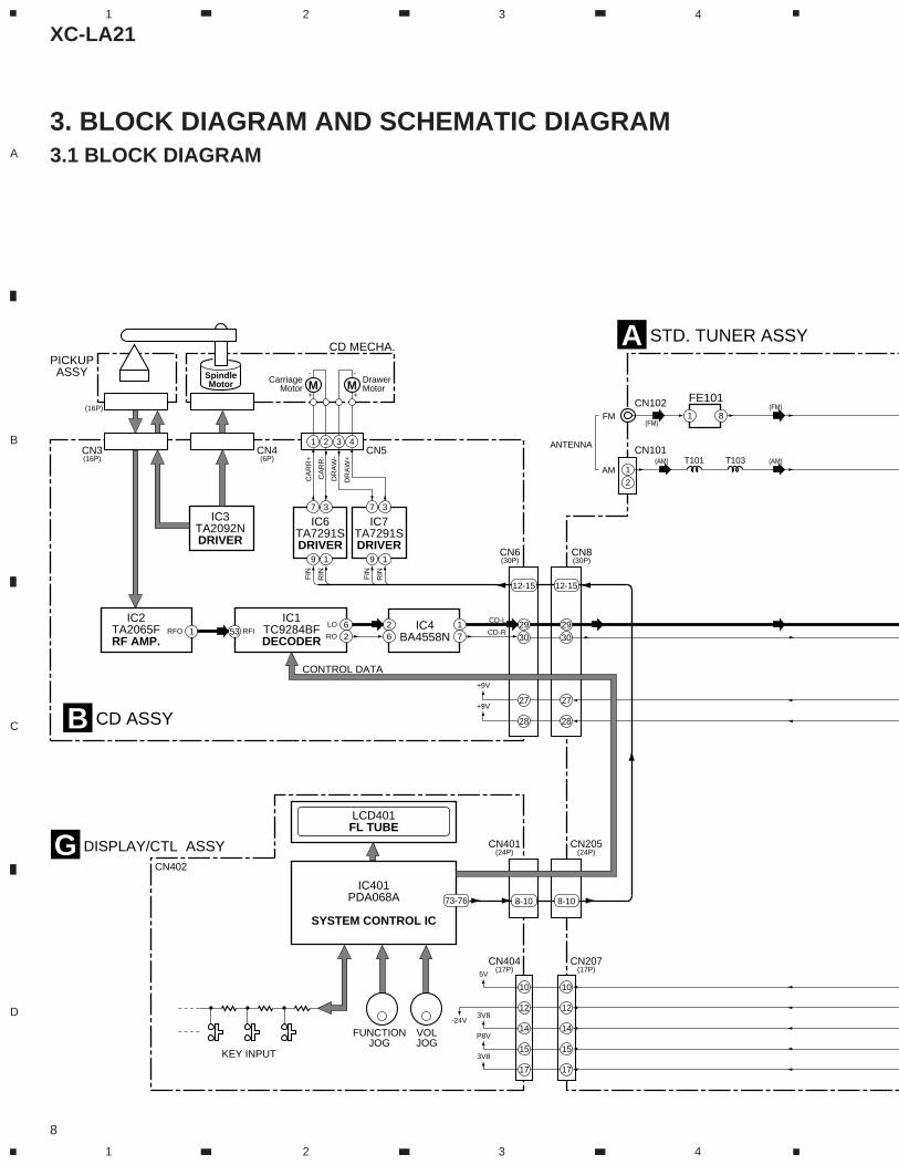
3. BLOCK DIAGRAM AND SCHEMATIC DIAGRAM3.1 BLOCK DIAGRAM
XC-LA21
9
A
B
C
D
5 6 7 8
5 6 7 8
31
7
9
12
13
10
7
9
12
13
10
CN206(16P)
CN202(16P)
J201(13P)
CN203(13P)
D AUX ASSY
CAUDIO ASSY
E RECT ASSY F TRANS ASSY
FM-IN TUNER-LTUNER-L
L-CD
R-CD
TUNER-R
TUNER-R
AM-RF
IC901BA4558NBUFFER
IC201BU4052BCSELECTOR
IC3025V REG.
TF302POWER
TRANSFORMER
TF303POWER
TRANSFORMER
D301-D304IC303
F306
AC IN
500mA/250V
IC305
IC307
IC202BH3854AFS
IC101LA1837NZ
1
27
17
16
11
13
11
13
CN13(3P)
CN208(3P)
1
3
1
3
9V
9V
1
CN11(14P)
CN301(14P)
+TUNER9V+TUNER9V
LIVE
NEUTRAL
+M9V
9V
+CD9V
+MCU9V
AC3.8V AC3.8V
AC3.8V
AC24V
MCUAC
AC3.8V
-24V
5V
5V
2
3
4
8
9
10
11
1
2
3
4
8
9
10
11
L
RAUXOUT
L
RAUXIN
5 7
3 1
31 24
L
RTo M-LA21
14
15 13
5
32
2 9
3 1
1
2
7
8
9
10
1
2
7
8
9
10
4
11
IC3019V REG.
CN302(12P)
SN302(12P)
3
3
9V
IC3046 6
9V4 2
CN204(3P)
Q908
Q909
CN208(3P)
31
: AUDIO SIGNAL ROUTE (TUNER)
: AUDIO SIGNAL ROUTE (RF/CD)(T)
: AUDIO SIGNAL ROUTE (AM)(AM)
: AUDIO SIGNAL ROUTE (FM)(FM)
: AUDIO SIGNAL ROUTE (AUX)(AU)
(AU)
(AU)(AU)(AU)
(AU
)
(T)
(AU)(AU)
(AU
)
(AU)
(AU
)
: AUDIO SIGNAL ROUTE (PHONES)(PH)
(T)
(T)(T)(FM)
(AM)
WH602(4P)
IC601STK411-230
POWER AMPLIFIER
RL601PLY-DPDT
L
R
SPEAKEROUT
18 14
22 15
1
(PH
)
CN22(8P)
SN602(8P)
IC504BA4558N
5 7
3 1
7
5
7
5
CN604(7P)
CN20(6P)
PHONESJK503
42
L-CH
R-CH
(PH)
L
R
From XC-LA21
3
5
M-LA21
4
LK501(4P)
1
4
XC-LA21
10
A
B
C
D
1 2 3 4
1 2 3 4
1 2 3 4 5 6 7 8 9 10 11 12 13 14 15 16
1 2 1 23 4 5 6 7 8 9 10 11 12 13 14 15 16
PICKUP ASSY
CN3
1 2 3 4 5 6 7 8 9 10 11 12 13 14 15 16 17
1 2 3 4 5 6 7 8 9 10 11 12 13 14 15 16 17
CN207
CN404
CN102
FM ANT1 2
CN101
AM ANT
CN6 CN8
1234
CN5CARRIAGEMOTOR
DRAWERMOTOR
CARR+
DGNDR-CHL-CH
EXTRA SWSP CLT
HOME SWCN2 SWCN1 SW
OP/CL SWFWD SWRVS SW
DMFDMRCMFCMR
CD POWERSLT
BUCKCCE
B3B2B1B0
MGAGDG
+9V+9V
CD-LCD-R
CARR-DRAW-DRAW+
123456
CN4DM+DM-FM+FM-SLT
GND
123456
CN2EXTRA SWHOME SWCOMCN2 SWCN1 SW
OP/CL SW7 FWD SW8
123456789101112131415161718192021222324252627282930
123456789
101112131415161718192021222324252627282930
CN401 CN205FWD SWRVS SW
OP/CL SWCN1 SWCN2 SW
HOM SWEXTRA SW
DMRDMFCMRCMF
CD-BUS0CD-BUS1CD-BUS2CD-BUS3CD-CCE
CD-BUCKCD POWERSYS-MUTE
CD-SW PUINCLOCK POWER
RDS-DATARDS-CLOCK
NC
CH
ANN
EL 0
TUN
ERC
HAN
NEL
1VO
L-D
ATA
VOL-
LATC
HVO
L-C
LOC
KPO
WER
CTR
LD
TS-P
LLC
LOC
K5V D
TS-P
LLPE
RIO
D-2
4VG
ND
3V8
P8V
DTS
-TD
ATA
3V8DTS-PLLSTEREO
242322212019181716151413121110987654321
242322212019181716151413121110987654321
RVS SW
M
M
CD ASSY(CD--PMT1E)CD
MECHA.
B
DISPLAY/CTLASSY(PMT101000041)
G
STD. TUNER ASSY(TUN-PMT1E-DL)
A
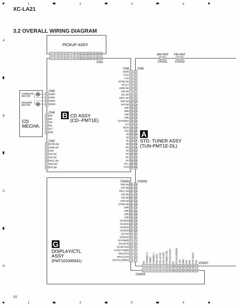
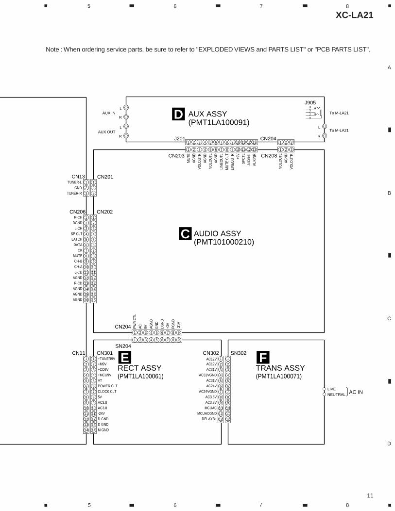
3.2 OVERALL WIRING DIAGRAM
XC-LA21
11
A
B
C
D
5 6 7 8
5 6 7 8
L
RAUX IN
L
RAUX OUT
123
123
CN13TUNER-L
GNDTUNER-R
1 2 3 4 5 6 7 8 9 10 11 12 13
1 2 3 4 5 6 7 8 9 10 11 12 13
CN203
J201
MU
TEAG
ND
VOLO
UTR
1 2 3
1 2 3
CN208
CN204
AGN
DVO
LOU
TR
VOLO
UTL
AGN
DVO
LOU
TLAG
ND
LIN
EOU
TLM
UTE
CLT
LIN
EOU
TR +9V
SPC
TLAU
XIN
LAU
XIN
R
1 2 3 4 5 6 7 8 9
1 2 3 4 5 6 7 8 9
CN204
SN204
PWR
CTL
AC 9V AGN
DG
ND
DG
ND
+3V
PGN
D-3
1V
CN206 CN202
CN201
R-CHDGND
L-CHSP CLTLATCH
DATACK
MUTECH-BCH-AL-CD
AGNDR-CD
AGNDAGNDAGND
12345678910111213141516
123456789
10111213141516
CN11 CN301
+M9V+TUNER9V
+CD9V+MCU9VVTPOWER CLTCLOCK CLT5VAC3.8AC3.8-24VD GNDD GNDM GND
1234567891011121314
123456789
1011121314
CN302 SN302
AC12VAC12V
AC31VAC31VGND
AC31VAC24V
AC24VGNDAC3.8VAC3.8VMCUAC
MCUACGNDRELAYB+
123456789101112
123456789
101112
LIVENEUTRAL AC IN
To M-LA21
To M-LA21
J905
AUX ASSY(PMT1LA100091)
AUDIO ASSY(PMT101000210)
RECT ASSY(PMT1LA100061)
C
D
ETRANS ASSY(PMT1LA100071)
F
L
R
Note : When ordering service parts, be sure to refer to "EXPLODED VIEWS and PARTS LIST" or "PCB PARTS LIST".
XC-LA21
12
A
B
C
D
1 2 3 4
1 2 3 4
CN
301
EC
N20
2C
CN
404
GC
N40
1G
CN6B
(AM)
(AM)
(AM)
(AM)
(FM)
(FM)
(FM)
(FM)
(FM
)
(AM
)
(AM)
(T)(T)
CN201C
010-849257-001A
008-314170-008A
008-685500-000A
037-
0035
34-1
00
019-000107-006A
012-007840-010A
012-006120-010A
042-104511-000A118-040102-002A
118-040102-002A
135-006116-160J
135-006232-300J
136-14PMT1-B00J
136-TOCB17-171J
136-FEBTVK-240J
136-03PMT1-B00J
007-200610-000A
009-607200-000A
003-020280-050
003-024010-050
003-020380-050
005-035100-000A
003-050010-050
A
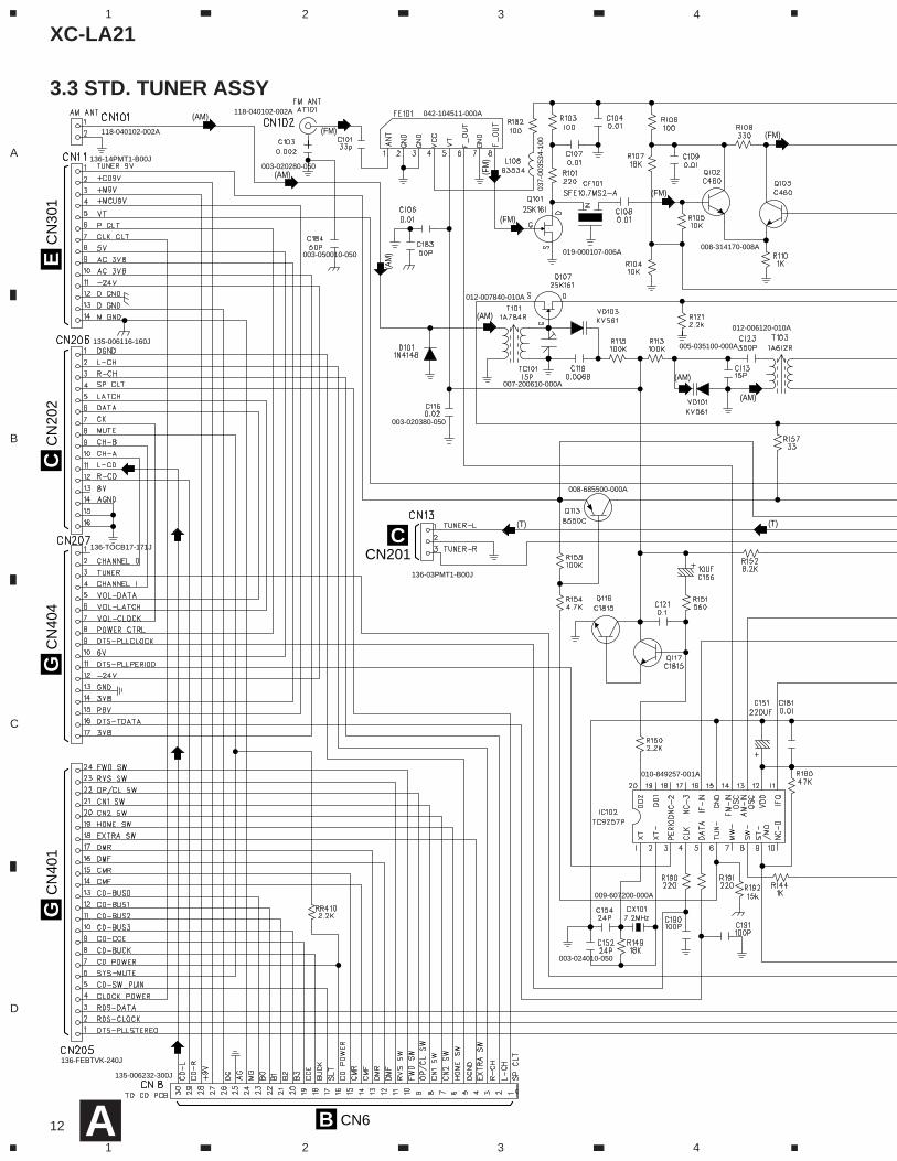
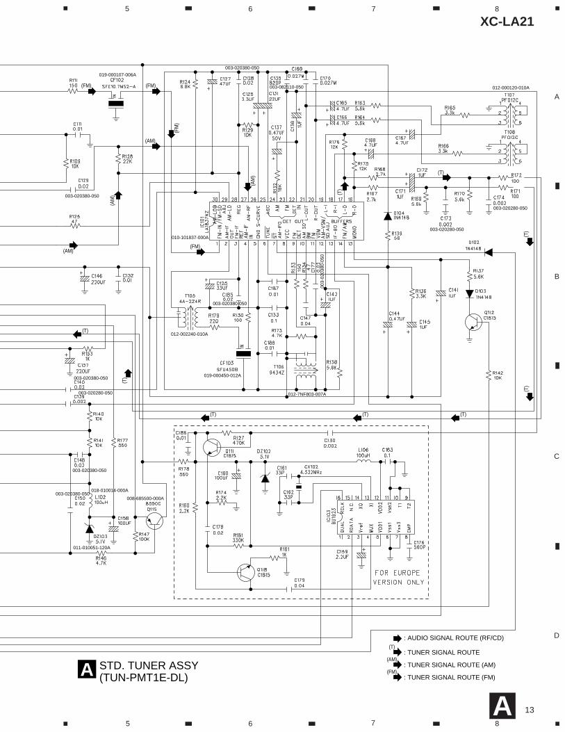
3.3 STD. TUNER ASSY
XC-LA21
13
A
B
C
D
5 6 7 8
5 6 7 8
STD. TUNER ASSY(TUN-PMT1E-DL)A
: AUDIO SIGNAL ROUTE (RF/CD)
: TUNER SIGNAL ROUTE(T)
: TUNER SIGNAL ROUTE (AM)(AM)
: TUNER SIGNAL ROUTE (FM)(FM)
(AM)
(AM
)
(AM
)
(AM)
(FM)
(FM)(FM)
(FM
)(T)
(T)
(T)
(T)
(T)(T)(T)
(T)
(T)
010-101837-000A
008-685500-000A
011-010051-120A
018-010014-000A
019-000107-006A
019-000450-012A
012-000120-010A
012-002240-010A
012-7NF803-007A
003-020280-050
003-020280-050
003-020280-050
003-020380-050
003-020380-050
003-020380-050
003-
0203
80-0
50
003-020380-050
003-020380-050
003-020380-050
003-082110-050
A
XC-LA21
14
A
B
C
D
1 2 3 4
1 2 3 4
CN
8A
CD
ME
CH
A.
Decorder
010-849284-000A
008-680500-000A
011-010056-120A
037-003534-100003-624052-050A
020-001693-000A
003-624052-050A
135-006232-301J
136-08PMT1-250J
B
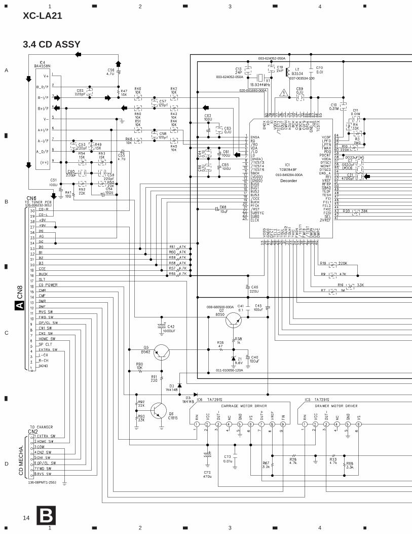
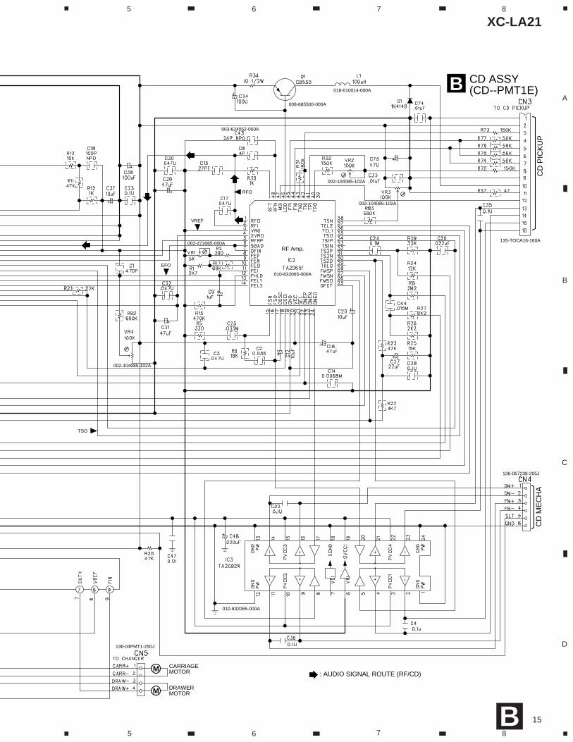
3.4 CD ASSY
XC-LA21
15
A
B
C
D
5 6 7 8
5 6 7 8
CD ASSY(CD--PMT1E)B
CD
PIC
KU
PC
D M
EC
HA
: AUDIO SIGNAL ROUTE (RF/CD)
VREF
EFO
RFO
TSO
M
M
CARRIAGEMOTOR
DRAWERMOTOR
RF Amp.
010-832065-000A
010-832065-000A
008-685500-000A
018-010014-000A
003-624052-050A
002-472065-000A
002-104085-102A
002-104085-102A
002-104085-102A
136-067238-205J
136-04PMT1-250J
135-TOCA16-160A
B
XC-LA21
16
A
B
C
D
1 2 3 4
1 2 3 4
010-400009-001A
008-685500-000A
011-010240-120A135-2001WS-140J
050-140060-200J
120-100470-000
136-03189D-200J
050-030160-200J
J903118-020202-000A
J904118-000244-000A
003-020380-050
008-801144-000A
008-801144-000A
008-801144-000A
CN206A
CN
11A
CN1C
CN904D
CN13A
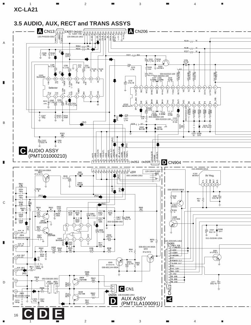
AUDIO ASSY(PMT101000210)
C
AUX ASSY (PMT1LA100091)D
(T)
(T)
(AU
)
(AU)
(AU)
(AU)
(AU)
(AU)(A
U)
(AU
)
(AU
)
(AU
)
(AU
)
(AU
)
(AU
)
(AU
)
(AU
)
(AU
)
9V Reg.
Selector
004-068350-100
004-068350-100
004-
0233
10-1
00
004-010310-100
004-010310-100
135-006116-160J135-PHS030-030J
C D E
3.5 AUDIO, AUX, RECT and TRANS ASSYS
XC-LA21
17
A
B
C
D
5 6 7 8
5 6 7 8
1235D6636140
124-035010-000A
124-010010-002A
124-010010-002A
124-010010-002A
011-024001-000A
025-230041-000A
025-230041-000A
019-500160-000A
003-010320-250A
003-010320-250A
124005020002
1233D4828140
008-685500-000A
011-020005-000A
011-024001-000A
011-024001-000A
011-024001-000A
011-010082-120A
136-09PMT1-C00J
050-120060-251J
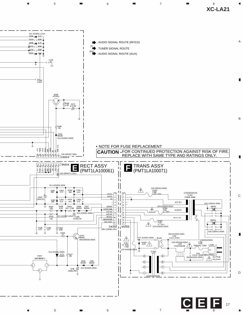
TRANS ASSY(PMT1LA100071)FRECT ASSY
(PMT1LA100061)E
LIVE
NEUTRAL
• NOTE FOR FUSE REPLACEMENTFOR CONTINUED PROTECTION AGAINST RISK OF FIRE.REPLACE WITH SAME TYPE AND RATINGS ONLY.
CAUTION -
: AUDIO SIGNAL ROUTE (RF/CD)
: TUNER SIGNAL ROUTE(T)
: AUDIO SIGNAL ROUTE (AUX)(AU)
011-010051-121A
011-024001-000A
135-005267-090J
E FC
XC-LA21
18
A
B
C
D
1 2 3 4
1 2 3 4
CN
205
AC
N20
7F
orD
OW
NLO
AD
A
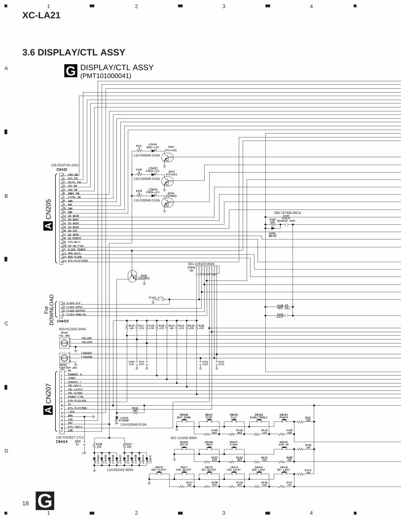
DISPLAY/CTL ASSY(PMT101000041)G
110-033045-013A
110-033045-013A
110-033045-013A
110-033040-013A
110-033162-003A
021-114165-000A
006-747300-05CA
001-229103-000A
003-H12203-204A
135-TOCB17-171J
135-FESTVK-240J
G
3.6 DISPLAY/CTL ASSY
XC-LA21
19
A
B
C
D
5 6 7 8
5 6 7 8
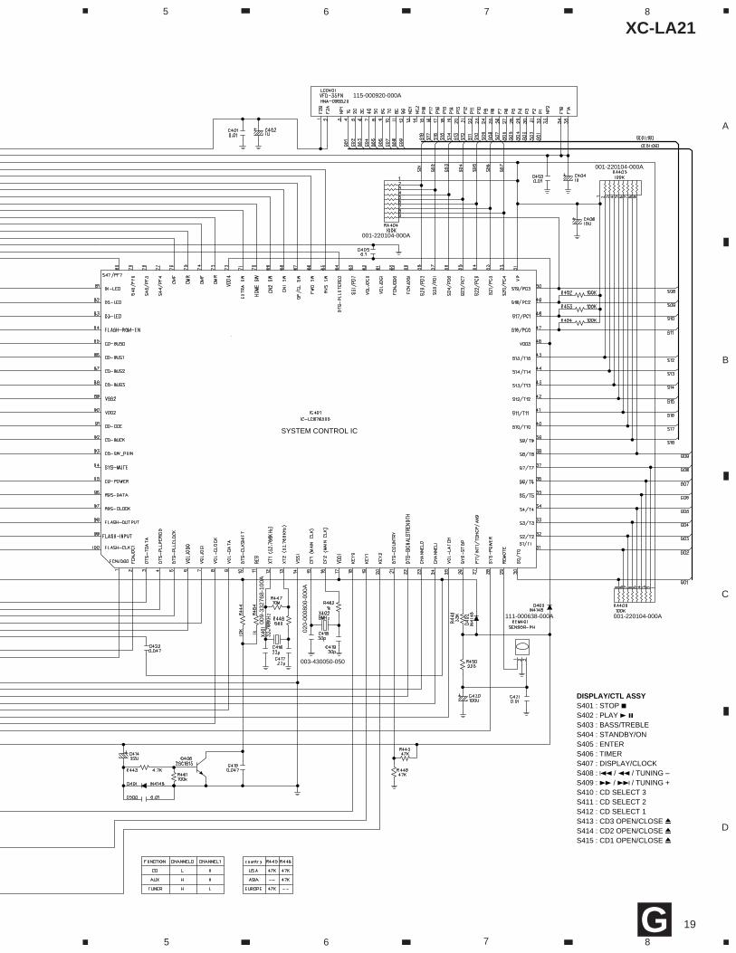
DISPLAY/CTL ASSYS401 : STOP 7S402 : PLAY 3 8S403 : BASS/TREBLES404 : STANDBY/ONS405 : ENTERS406 : TIMERS407 : DISPLAY/CLOCKS408 : 4 / 1 / TUNING –S409 : ¡ / ¢ / TUNING +S410 : CD SELECT 3S411 : CD SELECT 2S412 : CD SELECT 1S413 : CD3 OPEN/CLOSE 0S414 : CD2 OPEN/CLOSE 0S415 : CD1 OPEN/CLOSE 0
SYSTEM CONTROL IC
003-430050-050
001-220104-000A
001-220104-000A
001-220104-000A111-000638-000A
115-000920-000A
020-
0008
00-0
00A
009-
3327
68-1
00A
G
XC-LA21
20
A
B
C
D
1 2 3 4
1 2 3 4
W180
Q12
0
W12
8
R154
R192
W242
CN20
7
CN20
6
CN205
W24
1
W24
0W
235
W23
4
W23
3
W232
W23
0 CN11
W115
W14
1
W116
W11
8
W10
3
CN13
W10
2
W11
0
W11
1
W10
8
W10
5
W10
6
W10
7
R424
CN8
W123
W12
5
W12
4
W122
R155
Q113
W13
0
W121
W113
W12
9
W13
1
W12
7
W117
W12
6
W114
W10
9 W119
W120
W10
1
W10
4
RA40
2
R421
R413
R412 R411
R407
R408
R409
R410
D104
R142
C144
C167
Q112
T108
D103
R176
R175
C171C172
C142
R137
R139
R138
D102
R136
C141 C145
R170
R167
R168
R165
R166
R169
R157
R171
R172
C174C173
C146
C196
C170
T107
R147
Q115R178
DZ102
R161 R181
C178
Q118
R160
R199
C163
L106
C160 C179
C176
C159
C161
C162
CX102
IC103
UNRE
G+
MCU8V
M9V CD
9V
CD9V
M9V
DGND
MG
ND
MG
ND+5V
DGND
DGND
+5V
DGND
3V8
+5V DG
ND
AGND
AGND
AGND AGND
AGND
AGND
AGND
RED
RED
CONT
ACT
SIDE
CONTACT SIDE
15
10
5
1
20
15
10
5
1
1
30
25
20
15
10
5
15
10
5
1 1
10
5
1
15
10
5
1
16
15
1 NC
M GNDD GNDD GND-24VAC 3.8VAC 3.8V
5VC CLTP CLT
UNREG+
TU9V
MCU9VM9V
CD9V
5 LATCH4 SP CLT3 HLCH
1 HRCH2 D GND
6 DATA7 CK8 MUTE9 CH B
10 CH A11 CD L12 A GND13 CD R 16 LINE MUTE14 A GND
15 A GND
D GNDR CHL CH
EXTRASPCLT
HOMECN2 CN1O/C
FWDRVS DMFDMR CMF
CMRCD PWRSLTBUCK
CCEB3B2
B1B0 M GNDA GND
D GNDM 9V CD 9V
CD L
CD R
10 6V
13 GND
3 TUNER2 CH 0
4 CH 1
6 VOL-LATCH
8 POWER CTL15 P8V
5 VOL-DATA
7 VOL-CLOCK
9 DTS-CLOCK
11 DTS-PERIOD16 DTS-DATA
12 -24V
14 3.8V
17 3.8V
DTS-STEREORDS-CLOCKRDS-DATACLOCK-PWRCD-SW_PUNSYS-MUTECD-POWERCD-BUCKCD-CCECD-BUS3CD-BUS2CD-BUS1CD-BUS0CMFCMRDMFDMREXTRA SWHOME SWCN2 SWCN1 SWO/C SWRVS SWFWD SW
E
E
E
E
E
E
E
E
E
E
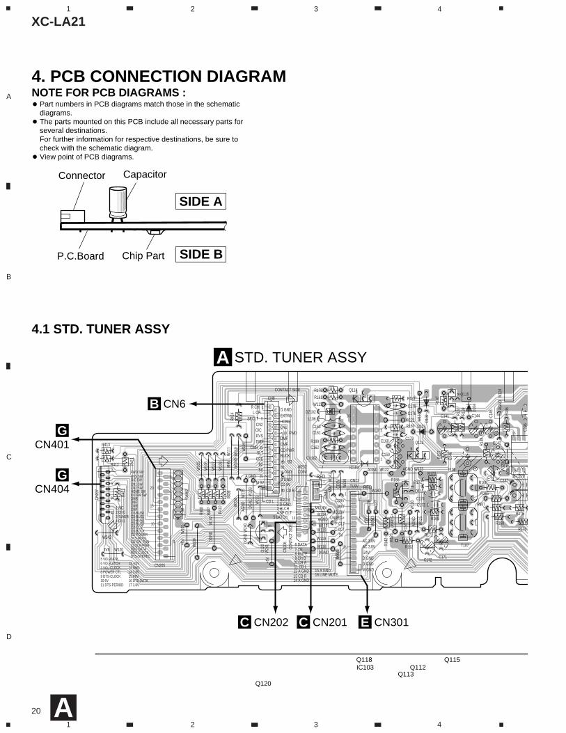
NOTE FOR PCB DIAGRAMS :4. PCB CONNECTION DIAGRAM
4.1 STD. TUNER ASSY
Part numbers in PCB diagrams match those in the schematicdiagrams.The parts mounted on this PCB include all necessary parts forseveral destinations.For further information for respective destinations, be sure tocheck with the schematic diagram.View point of PCB diagrams.
CapacitorConnector
P.C.Board Chip Part
SIDE A
SIDE B
Q120
Q112Q118
Q113
Q115IC103
CN6B
STD. TUNER ASSYA
CN404G
CN301ECN201CCN202C
CN401G
A
XC-LA21
21
A
B
C
D
5 6 7 8
5 6 7 8
C181
P105P104
P103
P102
C180 L107
R182
C182
C183
DZ10
3
P101
C184
W24
7
W246
W245
C188
C187
C186
W243
R180
W227
W226 CN10
2,
W12
4W
129 W
134
W13
2
W139
W140
W13
6
C190
C191
R191
R190
W13
3
R153C157
D104
W142
R134
W138
C168
R141
R140
C144
R121
R125
C167
D101
T106
C140
CF10
2
Q111
T105
IC101
R179
R176
R175
C177
C126
C125
C127
C131
C136
C137
C165
C166
P106
R124
R127
R174
C130
C142R138
C185
R136
C145
R129
R167
R168
R165
R166
R130
R173
R133
C132
R128
C128
R163 R1
64
C196
C133
C170
C169
R132
C197
C135
C129
C147
CF103
7 W143
Q10
5
W13
5
R146
5
R150 C139
R177
C158
L102
C148
C151 C1
50
R144
C152
C154
R149
CX101IC102
R104
R110
C106
C121
R151
C156
R152
Q11
7
Q11
6
C105
R109
C111
R108
R106
R107
C109
Q10
2
R105
C108
CF10
1
R102
R101
C107
C104
R103
Q10
1
C103
C102
C101
FE101
R115
C119
T101
Q107VD103
C120
TC10
1
R111
R113
VD101
C116
C113
C123
T103
CN10
1CN
102
AGND
AGND
AGND
+9V
+9V
AGND
+9V
WHITE
WHI
TE
TUNER BOARD
2015
1051
30252016
15 10
5
1
PMT1-01-01
E
E
E
E
E
E
E
EE
E
E
E
E
E
Q111IC101
Q116Q117Q101
Q102Q107
Q105IC102
A
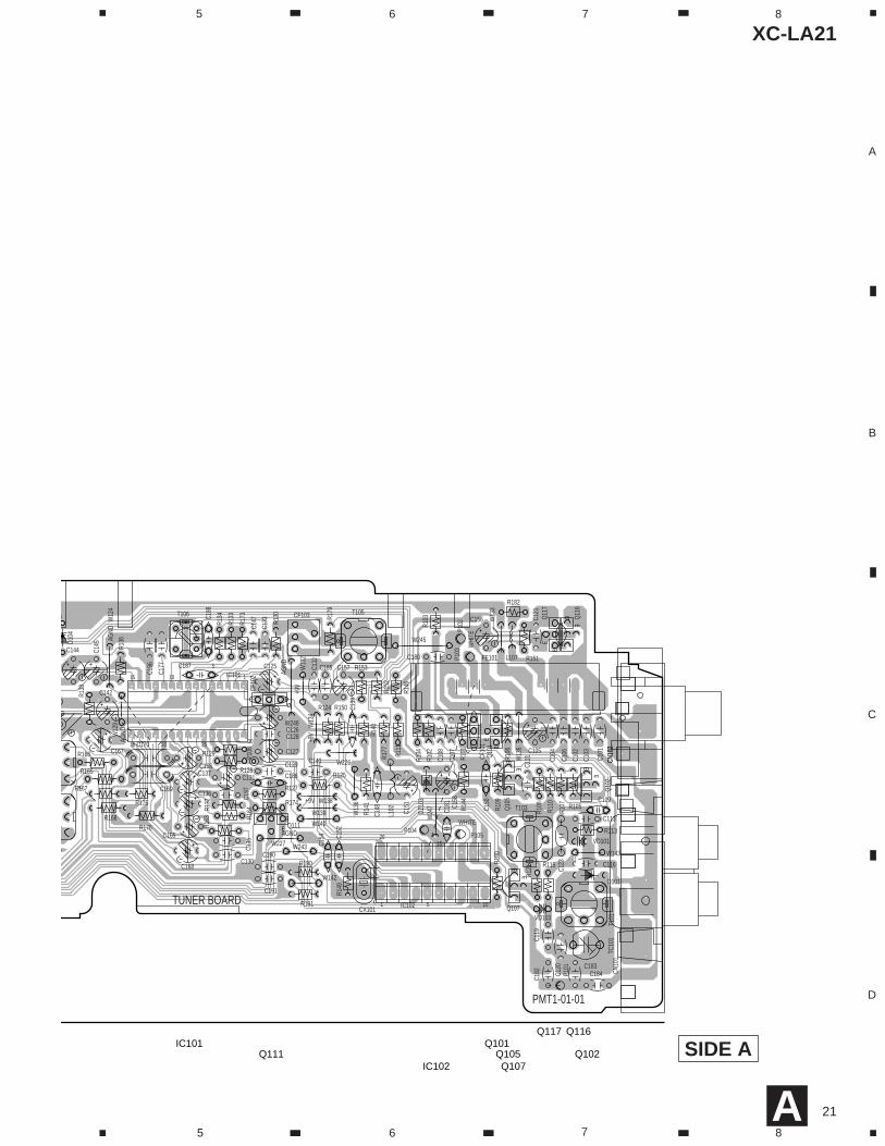
SIDE A
XC-LA21
22
A
B
C
D
1 2 3 4
1 2 3 4
GNDCD
TEO
TEB
FEB
FEO
GNDM
CD+9V
CD+9V
GNDCD
CD+9V
GNDCD
VREF
VREFCD+5V
CD+9V
CD+9VG
NDCD
GNDCD
CD+5V
CD+5V
CD+5V
GNDCD
GNDCD
GNDCD
GNDCD
GNDMCD+9V
GNDM
GNDCD
CD+5V
BLACK
RED
RED
RED
SERVO BOARD
15
10
5
1
5
1
20 15
105
1
5 10 15 2520 30
5
1
1
5 1
51
5
11
RFO
FEO
TSO
VREF
1G
NDSLTFM
-FM
+DM
-DM
+
CARR+CARR-DRAW-DRAW+
SPCLTL-CHR-CHDG
NDRVS
FWD
OP/CL CN1
CN2
COM
HOM
E
EXTRA
CDL+9VAGB0
B2CCESLT CDR+9V
DGDGB1B3BUCK
CMR CDPW
R
CMF
DMF
FWDCN1
DMR
RVSO
P/CLCN2HO
ME
SPCLTEXTRAL-CHDG
NDR-CH
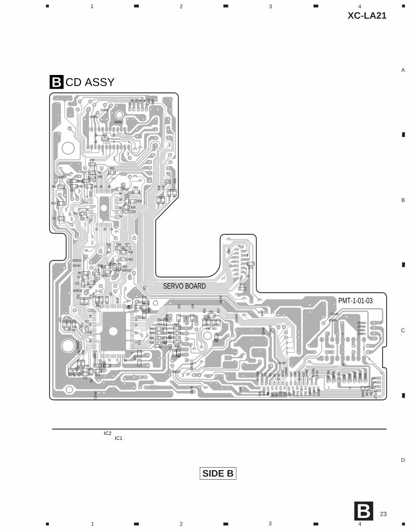
PMT-1-01-03
1
1
16
EE
EE
EE
E
E
C54
C75
W49
C56
W38
4
1
2
3
CN6
W36
W6
R72
R73
W37
CN3
VR3
W23
R39
R95
R94
W25
R36
D1
W42
CN1
W32
W33
W3
W26
W19
C4
C35
W8
C36C22
W39
W45
W44
W46
W48
W47
R61
R60
R35R56
R57
R58
R59
W43
W41
W40
W34
W30
W1
W2
W4
W5
W7
W21
C39
W14
W10W9
W12W
11
R34
W22
W28
W27
W24
R67
R28
R33
R68
C49
C50
R40
W35
R41
C41
R92
W15
W17
W16
W13
R2
R1
W18
W20
CN5
CN2
C73
C72C6
9
C30
C3
R9
IC6
IC5
K21
K20
K19
D3
D2
C40Z1R38Q
2
R93
Q6
C47
C42
R91
R90
Q5
Q1
IC4
L2
C34
C55
C51
C48
C38
C45
C16
C20
C27
C61
C62
C65
C68
VR2
VR1
VR4
L1
CN4
C31
C12
C9
IC3
X1
IC2
W29
IC6 IC4Q5 Q6IC5
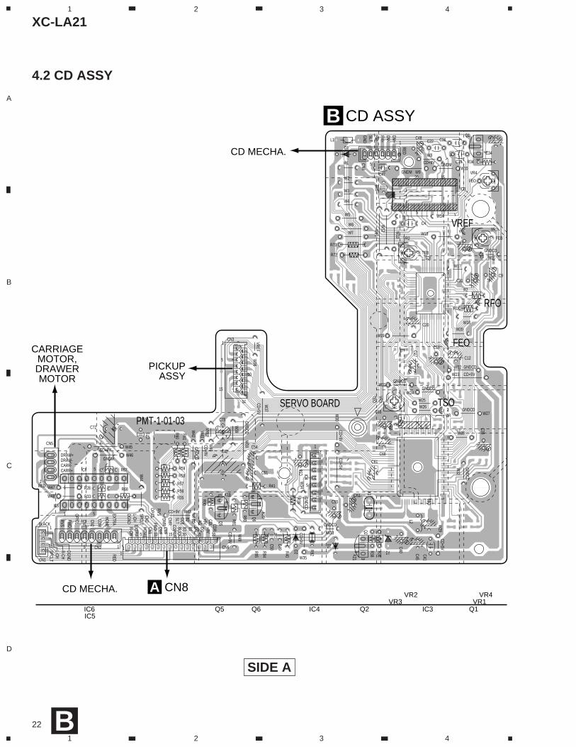
CARRIAGEMOTOR,DRAWERMOTOR
PICKUPASSY
CD MECHA.
CD MECHA.
CD ASSYB
CN8AIC3 Q1Q2
VR4VR1
VR2VR3
B
4.2 CD ASSY
SIDE A
XC-LA21
23
A
B
C
D
1 2 3 4
1 2 3 4
GND
CD
GNDM
CD+9V
CD+9V
GND
CD
CD+9
V
GNDCD
VREF
VREF
CD+5
V
CD+9
V
CD+9
VG
NDCD
GNDCD
CD+5V
CD+5
V
CD+5
V
GNDCD
GNDCD
GNDCD
GNDCD
GNDM
CD+9V
GNDM
CD+5V
GNDCD
SERVO BOARD
1
DGND
R-CHL-CH
SPCLT
CDR
+9V
DG DG B3B1 BUCK
CDPW
RCM
FDM
FFW
DCN
1HO
ME
EXTR
AR-
CHDG
NDL-
CHSP
CLT
CN2
OP/
CLRV
SDM
R
CMRSLT
CCE
B2B0AG+9V
CDL
5
10
15
GND
SLTFM-
FM+
DM-
DM+ 51
10 5 1
15 20
5
1
30
25
20
15
10 5
51
EXTR
A
HOM
E
COM
CN2
CN1
OP/
CL
FWD
RVS
5
5
1
1
1CARR+CARR-DRAW-DRAW+
80757065
6055
5045
40
3530
25
2015
105
38
2415
1
48 45 40
3530
25
20
1410
51
PMT-1-01-03
R96
R32
R75R77
R74
R76
R83
C26
C28
R30
R24
R31
R29
R27
R26
R25
C8
C43
C15
C1
R15
R82 C17C32
R17C24
C44
R23
R22
R16
R6
C25
C2
C14
R5
C29
C46
W31
R37
C59
R54
C60C57
C53
C52
R52
R53
R49
R48
R51R50
R46
R47
R55
C64
C66
C11
C23
C18
C19C10
R3
R10R13
R11
R66
R12R45R44
R43R42C6C7
C21
R8
R7R21
R20R19
C37
C58
C33
R4
IC1
C13
C71
C74
CD ASSYB
IC2IC1
B
SIDE B
XC-LA21
24
A
B
C
D
1 2 3 4
1 2 3 4
C246
C282
C281
R24
W22
8
W291
W29
0 W212
W214
W21
1
W213
W201
R206
D209
W28
8
R220
R202
R300
D257
D256
Q26
4
Q26
3
CN20
8
R229 CN204
R228
C278
Q26
2
C235
C237
D208
C236
D206
D205
D204
R290
P4
P3
P1 CN203
W20
7
R218
W216
W28
0
C229
R204
R203
R205
C209
C207
D202
D203
W209
W20
6
D201
CN201
W203
W252
W258
W259
W215
W26
8
C219
C218
C217
C234
R224
R223
R222
R221
C232
C231
C230
W20
4
R210
R215
R209
R208
C262
C270C2
15
W26
9
W26
7
R291
R292
R294
R293
Q25
8
Q25
9
Q26
1
Q26
0Q25
7
D252
C260
C225R2
83
R217
Q20
1
C212IC202
R216
C214
C216
C220
C221
C226
Q25
1
R219
C228
C224C223
C206
C210
C222
R226
R225
R227
C204
R211
C213
C227
C211
CN202
C203
C233IC201
R214
16
AGND
AGND
AGND
DGND
HPGND
DGND
GND
+9V
-31V
GND
BG
ND
AUDIO BOARD
1
15 10
511
15
10
51 1
5
1
AC
VIDE
O MUT
E
AGND
AGND
AGND
TUN-
L
TUN-
RAG
ND
AGND
-31VPGND+31V
DGND
GND
9V
PWRCTRL
CD-R
CD-L
CH-A
CH-B
MUT
ECKDA
TA
HPG
ND
LATC
HSP
-CLT
HPLC
H
HPRC
H
AGND
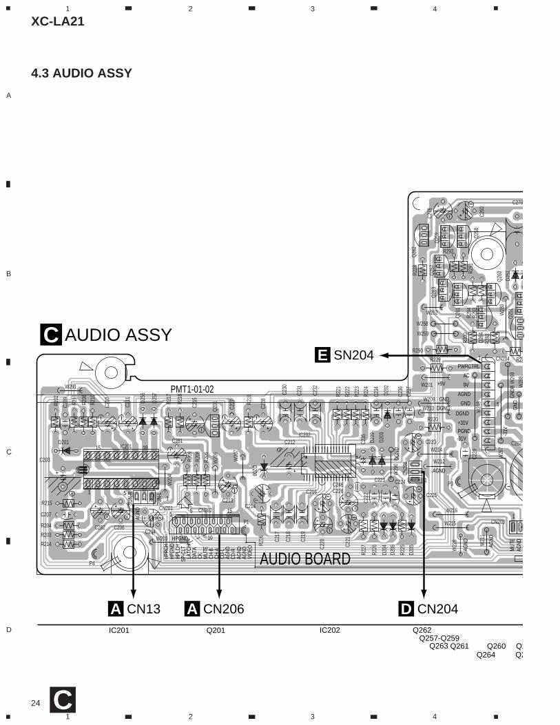
PMT1-01-02
AUDIO ASSYC
CN206A CN204D
SN204E
CN13AIC201 Q201
Q2Q2
Q264Q260Q261Q263
Q262IC202Q257-Q259
C
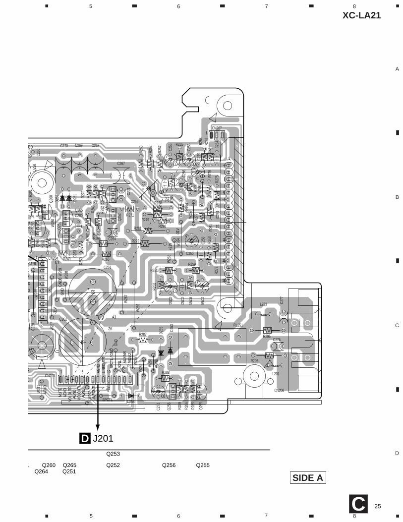
4.3 AUDIO ASSY
XC-LA21
25
A
B
C
D
5 6 7 8
5 6 7 8C
Q265C280
R249
R250
W29
2W21
1
W28
9
R277
W28
8
W28
7
W28
6
W28
5
W28
3
R300
Q26
4
Z6
R280
L201
R296
R295
C279
CN207
CN204
GND
SPCTL D254
R271
P2
CN203
W28
0
R251
R254
C229
W26
8
W26
3
R285
W23
5
C262
C261
C277
C276
C270 C268
L253
R267
W26
9
W26
7
W25
7
W26
4
R291
R294
R293
Q25
8
Q26
0
CN206
C263
D252
R282
R269
C271
C264R266
R270
C259
R263
C260
R264
C266
R276
R274
R275
C267
C269
R278
IC25
1
D251
R273
C265
R268
R260
C252
R253
R252
C257
R258
C256R2
56
C255
R257
R281
C254
R283
R286
R289
R288
C272
D255
R265
Q25
2
RL251
C258
R279
R287
Q25
1
Q25
3
R262
R261
C251
R255
C253
R259
R272
Q25
6D2
53
Q25
5
126
181
AGND
AGND
AGND
-31V
GND
BG
ND
-31V
+31V
1051
5
1
1
15
10
5
1
C
VIDE
O
MUT
E
A3
D
DV
D
D
V
RCTRL
AGND
AGND
AGND
AUXI
NL AUXI
NR
SPCT
L / G
ND+8
VLI
NEO
UTR
LINE
OUT
L
VOLO
UTL
VOLO
UTR
AGND
J201D
Q252 Q256 Q255Q251
Q253
Q265Q264
Q2601
SIDE A
XC-LA21
26
A
B
C
D
1 2 3 4
1 2 3 4
A4
A3
D309
Q305
Q303
Q301Q
302
W321
SN204
W303
W315
W314
R311
W305
W308
R310 R309
W310
W313
W316
W320
CN301
R301
ORN
D313
W319
W318
W317
W302D310 D307
W311
W312
D306
W309W304
W301
C302
YELSN302
CN302
C313
C308
C309
R302
R305
R303C307
D305
D308
R304
C301
C303
C304
C306C305
D301
D302
D304
D303
C310
C317
C318
R306R307
D312
IC302
IC301
AC 12V
AC 12V
AC 31V
AC 31V GND
AC 31VAC 24V
AC 24V GND
AC 3.8V
AC 3.8V
MCU AC
MCU AC GND
RELAY B+
AC 12V
AC 12V
AC 31V
AC 31V GND
AC 31V
AC 24V
AC 24V GND
AC 3.8V
AC 3.8V
MCU AC
MCU AC GND
RELAY B+
IC303
IC304
IC305
IC307
GRY
WHT
PUR
BLU
GRNYEL
ORNRED
BRN
RED
PRIMARDANGERPMT1LA
RECTIFIER BOARD
TRANSF
1 1
5 5
10 10
1212
14
10
5
1
5
15V
+MCU8V+M8V
A GND
+TUNER8V+CD8V
POWER GND
-31V
+31V
S GND
D GND
+8V
AC
M GND
D GNDD GND-24VAC 3.8VAC 3.8V
5VCLK CLT
P CLTVT
PMT1LA-01-06
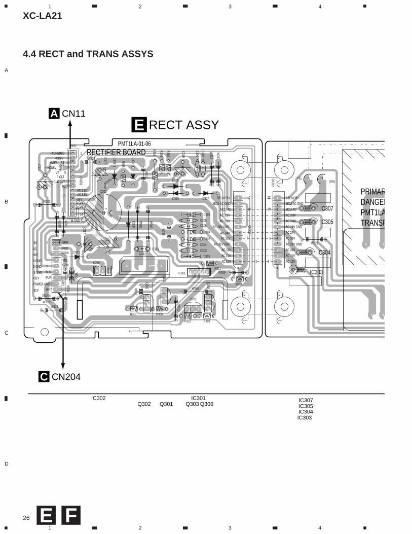
RECT ASSYE
CN204C
CN11A
IC302 IC301 IC307IC305IC304IC303
Q301Q302 Q303 Q306
E
4.4 RECT and TRANS ASSYS
F
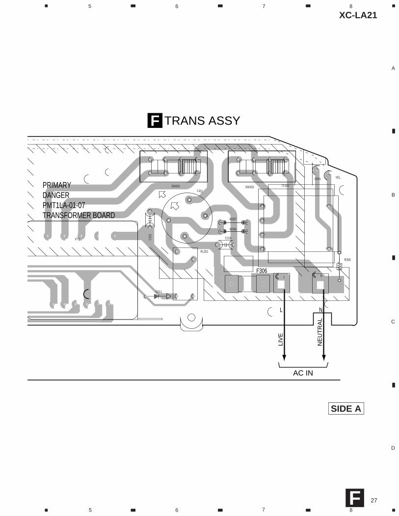
XC-LA21
27
A
B
C
D
5 6 7 8
5 6 7 8F
PT1
ORN. YEL.
NL
TF303
RL301
R308
C316C315
L301
W307
W306
D311
SW301 SW302
F306
PRIMARYDANGERPMT1LA-01-07TRANSFORMER BOARD
NL
TRANS ASSYF
AC IN
LIV
E
NE
UT
RA
L
SIDE A
XC-LA21
28
A
B
C
D
1 2 3 4
1 2 3 4
+9V
AGND
AGND
AGND
AGND
AGND
AGND
AUX BOARD
5
1
1
510
VIDE
O
MUT
E
AUXI
NR
AUXI
NLSP
CTL
+8V
LINE
OUT
LM
UTE
CLT
LINE
OUT
RAG
NDVO
LOUT
RAG
NDVO
LOUT
LAG
ND
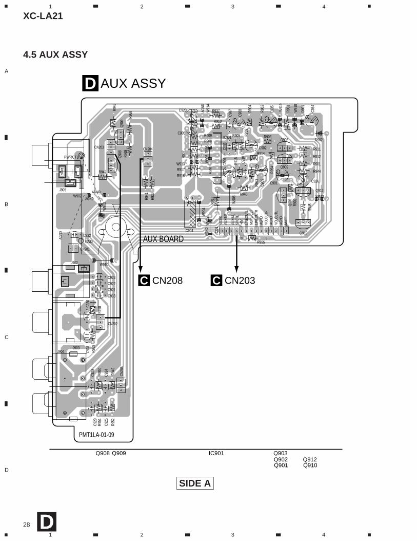
PMT1LA-01-09
CN20
5
CN204
J905
W91
9
PWRCTL
CN203
W91
8
R969
R968
D902
R962
C904
C935
C934
R961
D901
C933
C932
W91
5W
914
W913
C921
C922
C923
C931
C930
R959
R958
CN202
CN201
R955
Q912
R954
R953
C924
C925
W910
R952
R951
R950
R949
C920 R937
R901
R902
C901
J201
R945
Q910
Q90
9Q
908
R944
C926
R942
R943
R940
R939
R941
Q90
1
R912
Q902
R911
Q903
W902
GND
W912
W90
3 W90
6
J902
J903J904
W90
4W
905
R904
R914R9
35
C928
C905
C929
C909
C902
R907
R917
R908R909
C907
C903
C910
R915
R905
R916
R906
C908
R910
IC901 R903
R913
C906
AUX ASSYD
CN203CCN208C
Q909Q908 IC901 Q903Q912Q902Q910Q901
D
4.5 AUX ASSY
SIDE A
XC-LA21
29
A
B
C
D
1 2 3 4
1 2 3 4
D404
C421
C415
C500
R463
C419
W435
Q406
Q403
Q402
Q404
Q405
R462
C406
A
C501
R435
W409
CN404
C420
C407
W434
J433
CN15
SN15
C414
C408
R448
R447 G411
W428
C416
C417
R461
W432 R444
W420
C402
W426
R425W
403
LED412
W417
C401
C404
C497
C498
C499
C403
D403
W418
W404
R414
R418
R419
R135
R420
R442
R436
R431
R415
TP401
W416
W419
C409
W423
W424
W407
W406
W405
D401
R443
W425
R426
C418
X402X401
W427
R416
R417
R427
W410
D402
W429
R446
R445
R449
C410
C413
C412
W408
W422
R450
W415
W414
W413
W412
W411
CN402
R437
R438
R439
R440
R441
W421
R403
R402
R401
R460R434
R432
R433
R430
R429R428
RA403
R452
R453
R454
RA404
RA405RA406
C405
CN401
LCD401REM401
VR401VR402
LED408
LED411
LED409
LED410
LED404
LED407
LED405
LED406
LED403
LED402
LED401
SW405
SW406
SW407
S409S408
S401
S414
S415S412
S411
S402
S413S410S403
S404
IC401
PMT1
-01-
05
+5V
+5V
DGND
DGND
-24V
+5V-24V
DGND
AC3V8
P9V
AC3V8
+5V
+5V
+5V
CONT
ROL
BOAR
D
DISPLAY BOARD
1
1
105
1
510
1520
105
5
115
10
DIS CLTG
NDKEY 2KEY 1KEY 0+9V
D3 LEDD2 LEDD1 LED+5V
DIS CLTG
NDKEY 2KEY 1
KEY 0+9VD3 LED
D2 LEDD1 LED+5V
CLOCK
TIMER
ENTER
PLAY/PAUSE
STOP
UPDOWN
DISC3E
DISC2E
DISC1EDISC1
DISC2
DISC3
POWER
1 NC
1
BASS/TREBLEPMT1
-01-
05
PMT1-01-04
10 6V
13 GND
3 TUNER2 CHANNEL 0
4 CHANNEL 1
6 VOL-LATCH
8 POWER CTL
15 P9V
5 VOL-DATA
7 VOL-CLOCK
9 DTS-CLOCK
11 DTS-PERIOD
16 DTS-DATA
DTS-STEREORDS-CLOCKRDS-DATACLOCK_PWR
CD-POWERSYS-MUTECD-SW_PUN
CD-BUCKCD-CCECD-BUS3CD-BUS2CD-BUS1CD-BUS0CMF
CMRDMFDMREXTRA SWHOME SW
CN2 SWCN1 SWO/C SW
FWD SWRVS SW
12 -24V
14 3.8V
17 3.8V
E
E
EE
EE
EE
EE
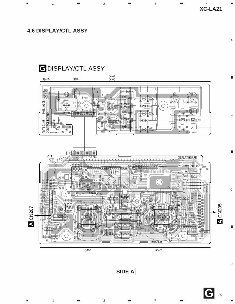
DISPLAY/CTL ASSYG
CN
205
A
CN
207
A
Q405 Q402Q403Q405
Q406 IC401
G
4.6 DISPLAY/CTL ASSY
SIDE A
30
XC-LA21
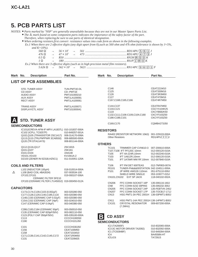
Mark No. Description Part No. Mark No. Description Part No.
B
Mark No. Description Part No. Mark No. Description Part No.
STD. TUNER ASSYSEMICONDUCTORS
IC101(ICREVA-AFM-IF-MPX LA1837L) 010-101837-000AIC102 (ICPLL TC9257P) 010-849257-001AQ102,Q105 (TRANSISTOR 2SC1417) 008-314170-008AQ113,Q115 (TRLPNPPWR 3CA8550) 008-685500-000AQ120 (TR DTA114YS) 008-801144-000A
Q112,Q116,Q117 2SC1815Q101,Q107 2SK161D101-D104 1N4148VD101,VD103 KV1561A-2DZ103 (ZENER IN-5231B,HZ5C1) 011-010051-120A
COILS AND FILTERSL102 (INDUCTOR 100µH) 018-010014-000A
L108 (BAD COIL #BA3534) 037-003534-100CF102,CF101 019-000107-006A
CERAMIC FILTER SFE10CF103 (CERAMIC FILTER LTU450G2) 019-000450-012A
CAPACITORSC173,C174,C139,C103 (0.002µF) 003-020280-050C177,C128,C129,C140,C185,C116 003-020380-050C148,C150 (CERAMIC CAP 0.02µF) 003-020380-050C154,C152 (CERAMIC CAP 24pF) 003-024010-050C147 (CERAMIC CAP 0.04µF) 003-040380-050
C288,C183,C184 (CERAMIC 50pF) 003-050010-050C135 (CERAMIC CAP 820pF/50V) 003-082110-050C123 (POLY CAP 350pF/50V) 005-035100-000AC113 CCCCH100D50C190 CCCCH101J50
C101 CCCCH330J50C156 CEAT100M50C158 CEAT101M10C171,C136,C141,C142,C145,C172 CEAT1R0M50C131 CEAT220M25
C146 CEAT221M10C125 CEAT330M16C126 CEAT3R3M50C127 CEAT470M16C167,C168,C165,C166 CEAT4R7M50
C144,C137 CEATR47M50C133,C121 CGCYX104K25C119 CKCYB682K50C132,C111,C106-C109,C104,C180 CKCYF103Z50C186-C188,C101 CKCYF103Z50
C169,C170 CQMBA273J50
RESISTORSRA402 (RESISTOR NETWORK 10kΩ) 001-229103-000AOther Resistors RD1/4PU J
OTHERSTC101 TRIMMER CAP CVN610-3 007-200610-000AT107,T108 IFT PF120C 10mm 012-000120-010AT105 IFT 4A-224R,10mm 012-002240-010AT103 IFT 1A612R,10mm 012-006120-010AT101 IFT 1A784R MW RF,10mm 012-007840-010A
T106 IFT FM DET 600TEAS 012-7NF803-007AFE101 TUNER-FN&&&00STATION 042-104511-000AP101 JP WIRE AWG26 110mm 051-675110-009J
SHIELD WIRE SINGLE 053-103077-015JCN101,CN102 EXT SP JACK 118-040102-002A
CN206 FFC CONN SOCKET 16P 135-006116-160JCN8 FFC CONN 6232 30PINS 135-006232-300JCN205 FFC CONN SOCKET 24P 135-FEBTVK-240JCN207 FFC CONN SOCKET 17P 135-TOCB17-171JCN13 HSG PMT1-3A PEC 2001H 136-03PMT1-B00J
CN11 HSG PMT1-14A PEC 2001H 136-14PMT1-B00JCX101 CRYSTAL RESONATOR 009-607200-000A
(7.2MHz)
CD ASSYSEMICONDUCTORS
IC2 (TA2065F) 010-832065-000AIC3 (IC MOTOR DRIVER TA2092) 010-832092-000AIC1 (TC9284BF) 010-849284-000AIC4 BA4558N-HTIC5,IC6 TA7291S
A
5. PCB PARTS LISTNOTES:•Parts marked by "NSP" are generally unavailable because they are not in our Master Spare Parts List.
•The mark found on some component parts indicates the importance of the safety factor of the part.Therefore, when replacing,be sure to use parts of identical designation.
•When ordering resistors,first convert resistance values into code form as shown in the following examples. Ex.1 When there are 2 effective digits (any digit apart from 0),such as 560 ohm and 47k ohm (tolerance is shown by J=5%, and K=10%).
560 Ω → 56 × 101 → 561 ........................................................ RD1/4PU 5 6 1 J47k Ω → 47 × 103 → 473 ........................................................ RD1/4PU 4 7 3 J0.5 Ω → R50 ..................................................................................... RN2H R 5 0 K1 Ω → 1R0 ..................................................................................... RS1P 1 R 0 K
Ex.2 When there are 3 effective digits (such as in high precision metal film resistors).5.62k Ω → 562 × 101 → 5621 ...................................................... RN1/4PC 5 6 2 1 F
LIST OF PCB ASSEMBLIES
STD. TUNER ASSY TUN-PMT1E-DLCD ASSY CD--PMT1EAUDIO ASSY PMT101000210AUX ASSY PMT1LA100091RECT ASSY PMT1LA100061
TRANS ASSY PMT1LA100071DISPLAY/CTL ASSY PMT101000041
31
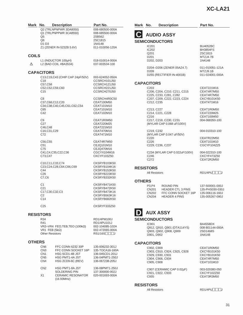
XC-LA21
Mark No. Description Part No. Mark No. Description Part No.Q2 (TRLNPNPWR 3DA8050) 008-680500-000AQ1 (TRLPNPPWR 3CA8550) 008-685500-000AQ5 2SB562Q6 2SC1815D1-D3 1N4148Z1 (ZENER IN-5232B 5.6V) 011-010056-120A
COILSL1 (INDUCTOR 100µH) 018-010014-000A
L2 (BAD COIL #BA3534) 037-003534-100
CAPACITORSC13,C19,C43 (CHIP CAP 24pF/50V) 003-624052-050AC18 CCSRCH101J50C57,C58 CCSRCH121J50C52,C52,C59,C60 CCSRCH221J50C15 CCSRCH270J50
C8 CCSRCH4R0C50C37,C68,C12,C20 CEAT100M50C34,C38,C40,C45,C61,C62,C54 CEAT101M10C65 CEAT101M10C42 CEAT102M10
C9 CEAT1R0M50C27 CEAT220M25C46,C48 CEAT221M10C16,C31,C29 CEAT470M16C72 CEAT471M10
C56,C55 CEAT4R7M50C51 CEJQ101M10C75 CEJQ470M16C41,C4,C35,C22,C36 CGCYX104M16C73,C47 CKCYF103Z50
C10,C11,C33,C74 CKSRYB103K50C23,C24,C28,C64,C66,C69 CKSRYB104K16C44 CKSRYB153K50C26 CKSRYB223K50C7,C6 CKSRYB332K50
C1 CKSRYB471K50C21 CKSRYB472K50C17,C30,C32,C3 CKSRYB473K16C2 CKSRYB563K16C14 CKSRYB682K50
C25 CKSRYF333Z50
RESISTORSR34 RD1/4PM100JR41 RD1/4PU101JVR2–VR4 FEO,TEB,TEO (100kΩ) 002-104085-102AVR1 FEB (5kΩ) 002-472065-000AOther Resistors RS1/16S J
OTHERSCN6 FFC CONN 6232 30P 135-006232-301JCN3 FFC CONN SOCKET 16P 135-TOCA16-160ACN1 HSG 5CD1-4B JST 136-045CD1-201JCN5 HSG PMT1-4A JST 136-04PMT1-250JCN4 HSG 2CD9-6C (REV) 136-067238-205J
CN2 HSG PMT1-8A JST 136-08PMT1-250JSOLDERING PIN 137-300000-002J
X1 CERAMIC RESONATOR 020-001693-000A(16.93MHz)
AUDIO ASSYSEMICONDUCTORS
IC201 BU4052BCIC202 BH3854FSQ201 2SC1815D201 MTZJ4.7BD202, D203 1N4148
D204–D206 (ZENER 05AZ4.7) 011-010051-121AD209 MTZJ9.1BD255 (RECTIFIER IN-4001B) 011-024001-000A
CAPACITORSC203 CEAT221M16C206, C204, C210, C211, C215 CEAT4R7M50C225, C233, C281, C282 CEAT4R7M50C207, C209, C222, C223, C224 CKCYB101K50C212, C235 CEAT471M16
C213, C227 CEAT1R0M50C214, C221, C228 CEAT220M25C216 CEAT100M50C217, C218, C230, C231 004-068350-100(MYLAR CAP 0.068 uF/100V)
C219, C232 004-010310-100(MYLAR CAP 0.047 uF/50V)C220 CEATR22M50C226 CEAT101M10C229, C236, C237 CGCYF104Z25
C234 (MYLAR CAP 0.022uF/100V) 004-022310-100C246 CKCYF473Z50C272 CEAT2R2M50
RESISTORSAll Resistors RD1/4PU J
OTHERSP3,P4 ROUND PIN 137-500001-000JCN201 HEADER CTL 3 PINS 135-PHS030-030JCN202 FFC CONN SOCKET 16P 135-006116-160JCN204 HEADER 4 PINS 135-005267-090J
AUX ASSYSEMICONDUCTORS
IC901 BA4558DXQ912, Q910, Q901 (DTA114YS) 008-801144-000AQ903, Q902, Q908, Q909 2SD1468SD901, D902 1N4148
CAPACITORSC902, C909 CEAT1R0M50C903, C910, C924, C925, C928 CKCYB101K50C929, C930, C931 CKCYB101K50C904, C906, C934 CEAT4R7M50C905, C908 CEAT101M10
C907 (CERAMIC CAP 0.02µF) 003-020380-050C921, C922, C933 CKCYF102Z50C935 CEAT3R3M50
RESISTORSAll Resistors RD1/4PU J
C
D
32
XC-LA21
Mark No. Description Part No. Mark No. Description Part No.
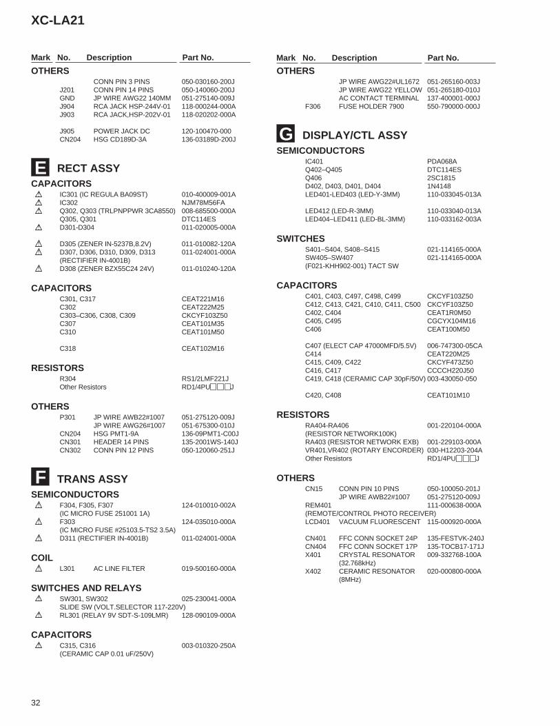
OTHERSCONN PIN 3 PINS 050-030160-200J
J201 CONN PIN 14 PINS 050-140060-200JGND JP WIRE AWG22 140MM 051-275140-009JJ904 RCA JACK HSP-244V-01 118-000244-000AJ903 RCA JACK,HSP-202V-01 118-020202-000A
J905 POWER JACK DC 120-100470-000CN204 HSG CD189D-3A 136-03189D-200J
RECT ASSYCAPACITORS IC301 (IC REGULA BA09ST) 010-400009-001A IC302 NJM78M56FA Q302, Q303 (TRLPNPPWR 3CA8550) 008-685500-000A
Q305, Q301 DTC114ES D301-D304 011-020005-000A
D305 (ZENER IN-5237B,8.2V) 011-010082-120A D307, D306, D310, D309, D313 011-024001-000A
(RECTIFIER IN-4001B) D308 (ZENER BZX55C24 24V) 011-010240-120A
CAPACITORSC301, C317 CEAT221M16C302 CEAT222M25C303–C306, C308, C309 CKCYF103Z50C307 CEAT101M35C310 CEAT101M50
C318 CEAT102M16
RESISTORSR304 RS1/2LMF221JOther Resistors RD1/4PU J
OTHERSP301 JP WIRE AWB22#1007 051-275120-009J
JP WIRE AWG26#1007 051-675300-010JCN204 HSG PMT1-9A 136-09PMT1-C00JCN301 HEADER 14 PINS 135-2001WS-140JCN302 CONN PIN 12 PINS 050-120060-251J
TRANS ASSYSEMICONDUCTORS F304, F305, F307 124-010010-002A
(IC MICRO FUSE 251001 1A) F303 124-035010-000A
(IC MICRO FUSE #25103.5-TS2 3.5A) D311 (RECTIFIER IN-4001B) 011-024001-000A
COIL L301 AC LINE FILTER 019-500160-000A
SWITCHES AND RELAYS SW301, SW302 025-230041-000A
SLIDE SW (VOLT.SELECTOR 117-220V) RL301 (RELAY 9V SDT-S-109LMR) 128-090109-000A
CAPACITORS C315, C316 003-010320-250A
(CERAMIC CAP 0.01 uF/250V)
OTHERSJP WIRE AWG22#UL1672 051-265160-003JJP WIRE AWG22 YELLOW 051-265180-010JAC CONTACT TERMINAL 137-400001-000J
F306 FUSE HOLDER 7900 550-790000-000J
DISPLAY/CTL ASSYSEMICONDUCTORS
IC401 PDA068AQ402–Q405 DTC114ESQ406 2SC1815D402, D403, D401, D404 1N4148LED401-LED403 (LED-Y-3MM) 110-033045-013A
LED412 (LED-R-3MM) 110-033040-013ALED404–LED411 (LED-BL-3MM) 110-033162-003A
SWITCHESS401–S404, S408–S415 021-114165-000ASW405–SW407 021-114165-000A(F021-KHH902-001) TACT SW
CAPACITORSC401, C403, C497, C498, C499 CKCYF103Z50C412, C413, C421, C410, C411, C500 CKCYF103Z50C402, C404 CEAT1R0M50C405, C495 CGCYX104M16C406 CEAT100M50
C407 (ELECT CAP 47000MFD/5.5V) 006-747300-05CAC414 CEAT220M25C415, C409, C422 CKCYF473Z50C416, C417 CCCCH220J50C419, C418 (CERAMIC CAP 30pF/50V) 003-430050-050
C420, C408 CEAT101M10
RESISTORSRA404-RA406 001-220104-000A(RESISTOR NETWORK100K)RA403 (RESISTOR NETWORK EXB) 001-229103-000AVR401,VR402 (ROTARY ENCORDER) 030-H12203-204AOther Resistors RD1/4PU J
OTHERSCN15 CONN PIN 10 PINS 050-100050-201J
JP WIRE AWB22#1007 051-275120-009JREM401 111-000638-000A(REMOTE/CONTROL PHOTO RECEIVER)LCD401 VACUUM FLUORESCENT 115-000920-000A
CN401 FFC CONN SOCKET 24P 135-FESTVK-240JCN404 FFC CONN SOCKET 17P 135-TOCB17-171JX401 CRYSTAL RESONATOR 009-332768-100A
(32.768kHz)X402 CERAMIC RESONATOR 020-000800-000A
(8MHz)
F
E
G
33
XC-LA21
CD TEST DISC(YEDS-7)
Precisescrewdriver
screwdriver(small)
screwdriver(medium)
screwdriver(large)
Dual-traceoscilloscope(10 : 1 probe)
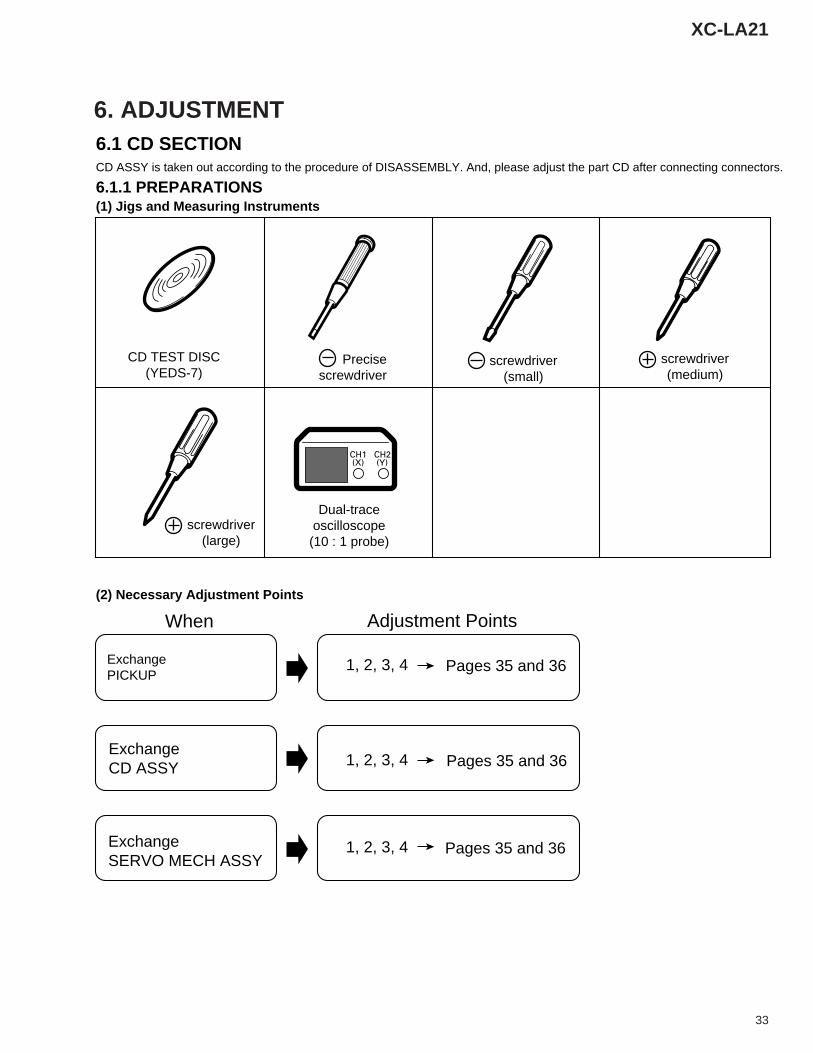
(1) Jigs and Measuring Instruments
(2) Necessary Adjustment Points
6.1 CD SECTION
6.1.1 PREPARATIONSCD ASSY is taken out according to the procedure of DISASSEMBLY. And, please adjust the part CD after connecting connectors.
When
ExchangePICKUP
1, 2, 3, 4
1, 2, 3, 4
1, 2, 3, 4
ExchangeCD ASSY
ExchangeSERVO MECH ASSY
Adjustment Points
Pages 35 and 36
Pages 35 and 36
Pages 35 and 36
6. ADJUSTMENT
34
XC-LA21
4
1
2
3
C46
W6
R72
R73
VR3
W23
W25
D1
W3
W26
W19
C4
C35
W8
C36C22
W30
W1
W2
W4
W5
W7
W21
C39
W14
W10W9
W12W
11R34
W22
W28
W27
W24
W15
W17
W16
W13
R2
R1
W18
W20
C47
Q1
C34
C48
C38
C16
C20
C27
C65
C68
VR2
VR1
VR4
L1
CN4
C31
C29
C12
C9
IC3
TEO
TEB
FEO
FEO
CCD+5V
GNDCD
GNDCD
GNDCD
GNDCD
GNDMCD+9V
GNDM
GNDCD
CD+5V
RED
O BOARD
5
1
20 15
105
1
RFO
FEO
TSO
VREF
1
GND
SLTFM
-FM
+DM
-DM
+
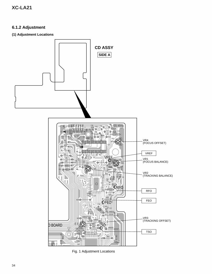
VR1(FOCUS BALANCE)
VR2(TRACKING BALANCE)
VR4(FOCUS OFFSET)
VR3(TRACKING OFFSET)
Fig. 1 Adjustment Locations
CD ASSY
6.1.2 Adjustment
(1) Adjustment Locations
SIDE A
RFO
VREF
FEO
TSO
35
XC-LA21
41
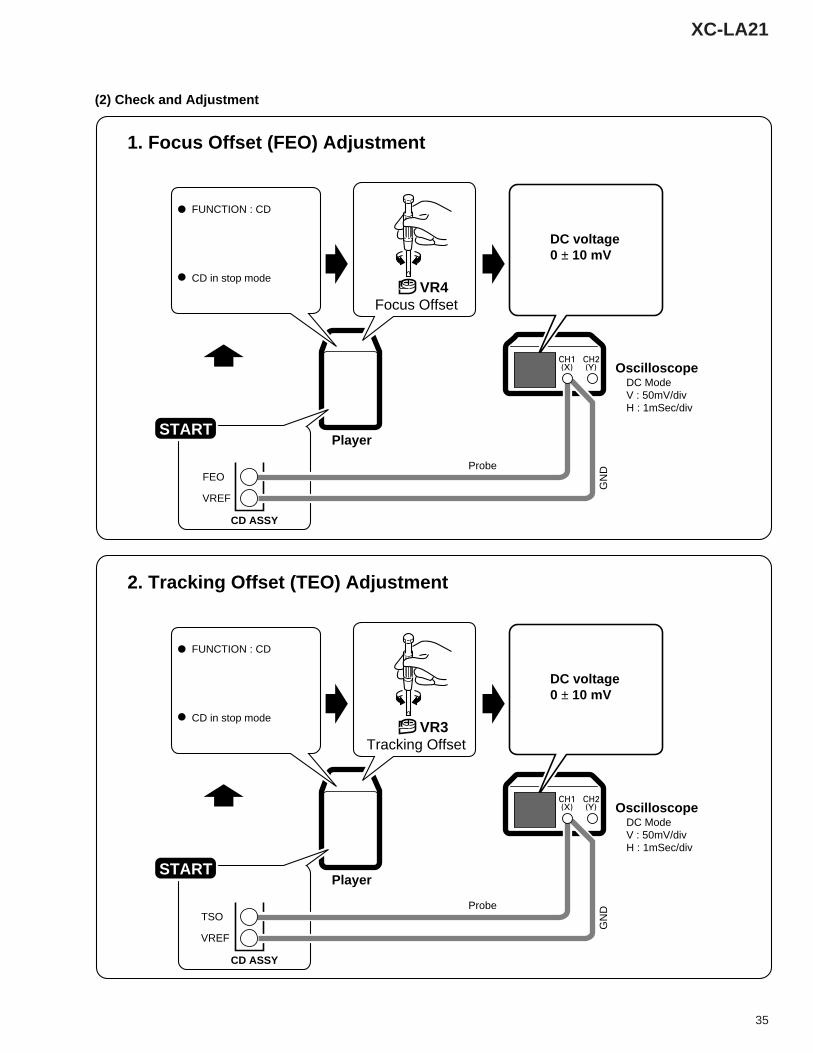
1. Focus Offset (FEO) Adjustment
(2) Check and Adjustment
FUNCTION : CD
CD in stop modeVR4
Focus Offset
DC voltage0 ± 10 mV
OscilloscopeDC ModeV : 50mV/divH : 1mSec/div
GN
DProbe
PlayerSTART
CD ASSY
FEO
VREF
41
2. Tracking Offset (TEO) Adjustment
FUNCTION : CD
CD in stop modeVR3
Tracking Offset
DC voltage0 ± 10 mV
OscilloscopeDC ModeV : 50mV/divH : 1mSec/div
GN
DProbe
PlayerSTART
CD ASSY
TSO
VREF
36
XC-LA21
42
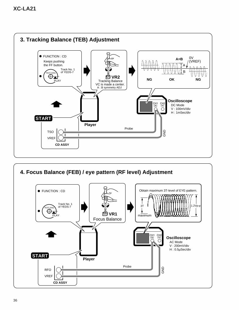
3. Tracking Balance (TEB) Adjustment
FUNCTION : CD
TEST DISC
PLAY
Track No. 1of YEDS-7
Track No. 1of YEDS-7
VR2Tracking Balance
0V(VREF)Keeps pushing
the FF button.
VC is made a center.A : B symmetry ADJ
OscilloscopeDC ModeV : 100mV/divH : 1mSec/div
GN
D
ProbePlayer
A=B
NGOKNG
A
B
CD ASSY
TSO
VREF
START
41
4. Focus Balance (FEB) / eye pattern (RF level) Adjustment
FUNCTION : CD
TEST DISC
PLAY VR1Focus Balance
maximum
Obtain maximum 3T-level of EYE-pattern.
1.2Vp-p3T
OscilloscopeAC ModeV : 200mV/divH : 0.5µSec/div
GN
DProbe
PlayerSTART
CD ASSY
RFO
VREF
37
XC-LA21
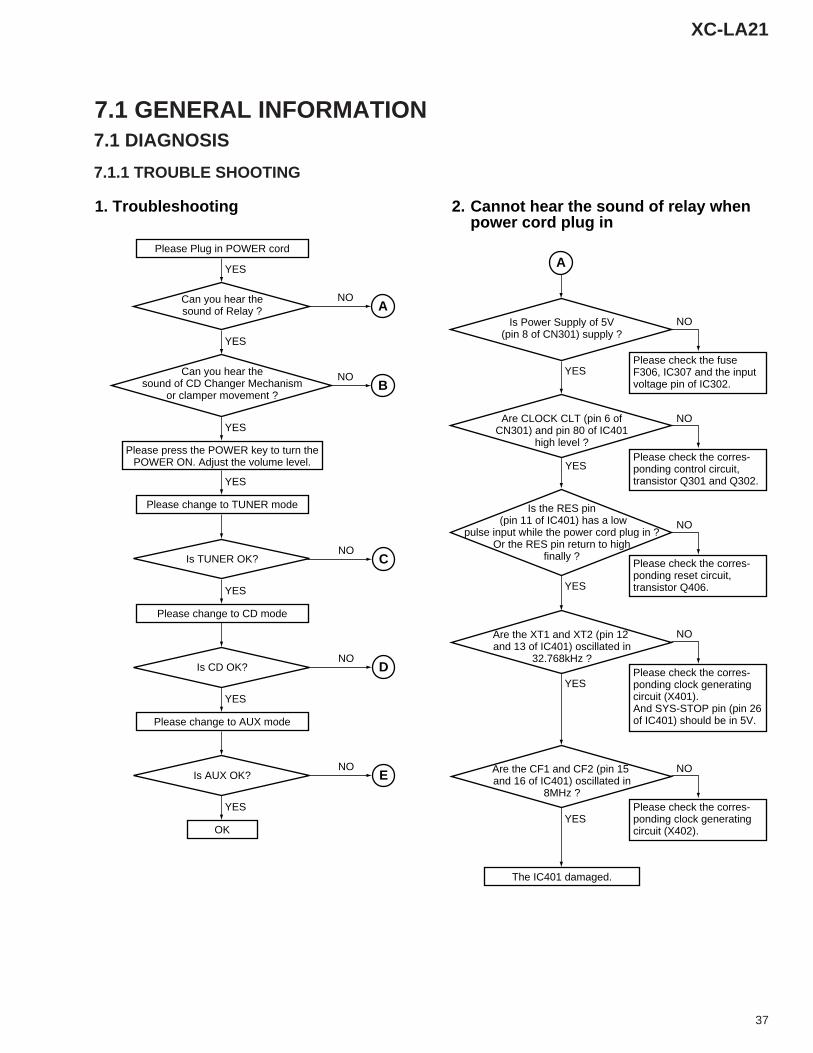
7.1 GENERAL INFORMATION7.1 DIAGNOSIS
7.1.1 TROUBLE SHOOTING
Please Plug in POWER cord
Can you hear thesound of Relay ?
Is TUNER OK?
Please change to TUNER mode
Please check the fuse F306, IC307 and the input voltage pin of IC302.
Please press the POWER key to turn thePOWER ON. Adjust the volume level.
YES
NO
Is CD OK?
Can you hear thesound of CD Changer Mechanism
or clamper movement ?
YES
YES
YES
YES
Please change to CD mode
YES
Is AUX OK?
Please change to AUX mode
YES
OK
YES
The IC401 damaged.
YES
Is Power Supply of 5V(pin 8 of CN301) supply ?
YES
Are CLOCK CLT (pin 6 ofCN301) and pin 80 of IC401
high level ?
Are the XT1 and XT2 (pin 12 and 13 of IC401) oscillated in
32.768kHz ?
YES
Are the CF1 and CF2 (pin 15 and 16 of IC401) oscillated in
8MHz ?
YES
Is the RES pin (pin 11 of IC401) has a low
pulse input while the power cord plug in ?Or the RES pin return to high
finally ?NO
NO
NO
NO
NO
Please check the corres-ponding control circuit,transistor Q301 and Q302.
NO
Please check the corres-ponding reset circuit,transistor Q406.
NO
Please check the corres-ponding clock generatingcircuit (X401). And SYS-STOP pin (pin 26of IC401) should be in 5V.
NO
Please check the corres-ponding clock generatingcircuit (X402).
NO
1. Troubleshooting 2. Cannot hear the sound of relay whenpower cord plug in
A
A
B
C
D
E
38
XC-LA21
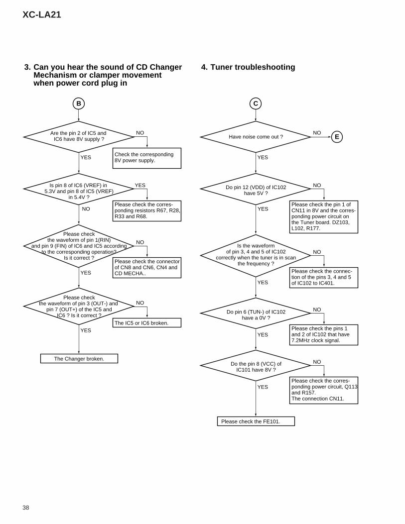
Check the corresponding8V power supply.YES
The Changer broken.
Are the pin 2 of IC5 and IC6 have 8V supply ?
NO
Is pin 8 of IC6 (VREF) in 5.3V and pin 8 of IC5 (VREF)
in 5.4V ?
Please checkthe waveform of pin 3 (OUT-) and
pin 7 (OUT+) of the IC5 andIC6 ? Is it correct ?
YES
YES
Please checkthe waveform of pin 1(RIN)
and pin 9 (FIN) of IC6 and IC5 accordingto the corresponding operation?
Is it correct ?
NO
Please check the corres-ponding resistors R67, R28,R33 and R68.
YES
Please check the connectorof CN8 and CN6, CN4 andCD MECHA..
NO
The IC5 or IC6 broken.
NO
3. Can you hear the sound of CD ChangerMechanism or clamper movementwhen power cord plug in
YES
Have noise come out ?
YES
Do pin 12 (VDD) of IC102have 5V ?
Do pin 6 (TUN-) of IC102have a 0V ?
YES
YES
Is the waveformof pin 3, 4 and 5 of IC102
correctly when the tuner is in scanthe frequency ?
NO
Please check the pin 1 ofCN11 in 8V and the corres-ponding power circuit onthe Tuner board. DZ103,L102, R177.
NO
Please check the connec-tion of the pins 3, 4 and 5of IC102 to IC401.
Please check the pins 1 and 2 of IC102 that have 7.2MHz clock signal.
NO
NO
Do the pin 8 (VCC) ofIC101 have 8V ?
YES
Please check the corres-ponding power circuit, Q113and R157. The connection CN11.
Please check the FE101.
NO
4. Tuner troubleshooting
E
CB
39
XC-LA21
NO
OK
Please push FWD key or REW key
Please tune the CD servo circuit
YES
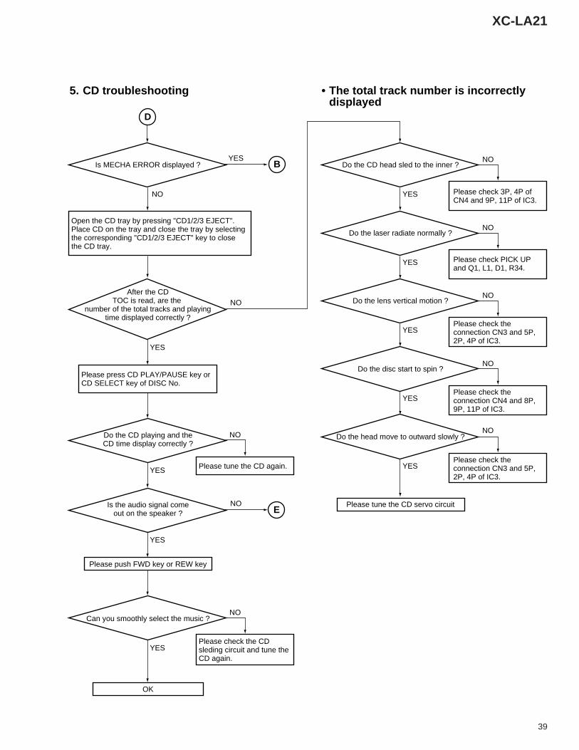
Is MECHA ERROR displayed ?
YES
Do the CD head sled to the inner ?
YES
Do the CD playing and theCD time display correctly ?
Can you smoothly select the music ?
YES
YES
Is the audio signal comeout on the speaker ?
After the CDTOC is read, are the
number of the total tracks and playingtime displayed correctly ?
YES
Open the CD tray by pressing "CD1/2/3 EJECT".Place CD on the tray and close the tray by selectingthe corresponding "CD1/2/3 EJECT" key to closethe CD tray.
Please press CD PLAY/PAUSE key or CD SELECT key of DISC No.
Please tune the CD again.
NO
Please check the CD sleding circuit and tune theCD again.
Please check 3P, 4P of CN4 and 9P, 11P of IC3.
Please check the connection CN3 and 5P, 2P, 4P of IC3.
Please check the connection CN3 and 5P, 2P, 4P of IC3.
Please check the connection CN4 and 8P, 9P, 11P of IC3.
Please check PICK UP and Q1, L1, D1, R34.
NO
NO
B
D
NOE
5. CD troubleshooting • The total track number is incorrectlydisplayed
NO
YES
Do the laser radiate normally ?NO
YES
Do the lens vertical motion ?NO
YES
Do the disc start to spin ?NO
YES
Do the head move to outward slowly ?NO
40
XC-LA21
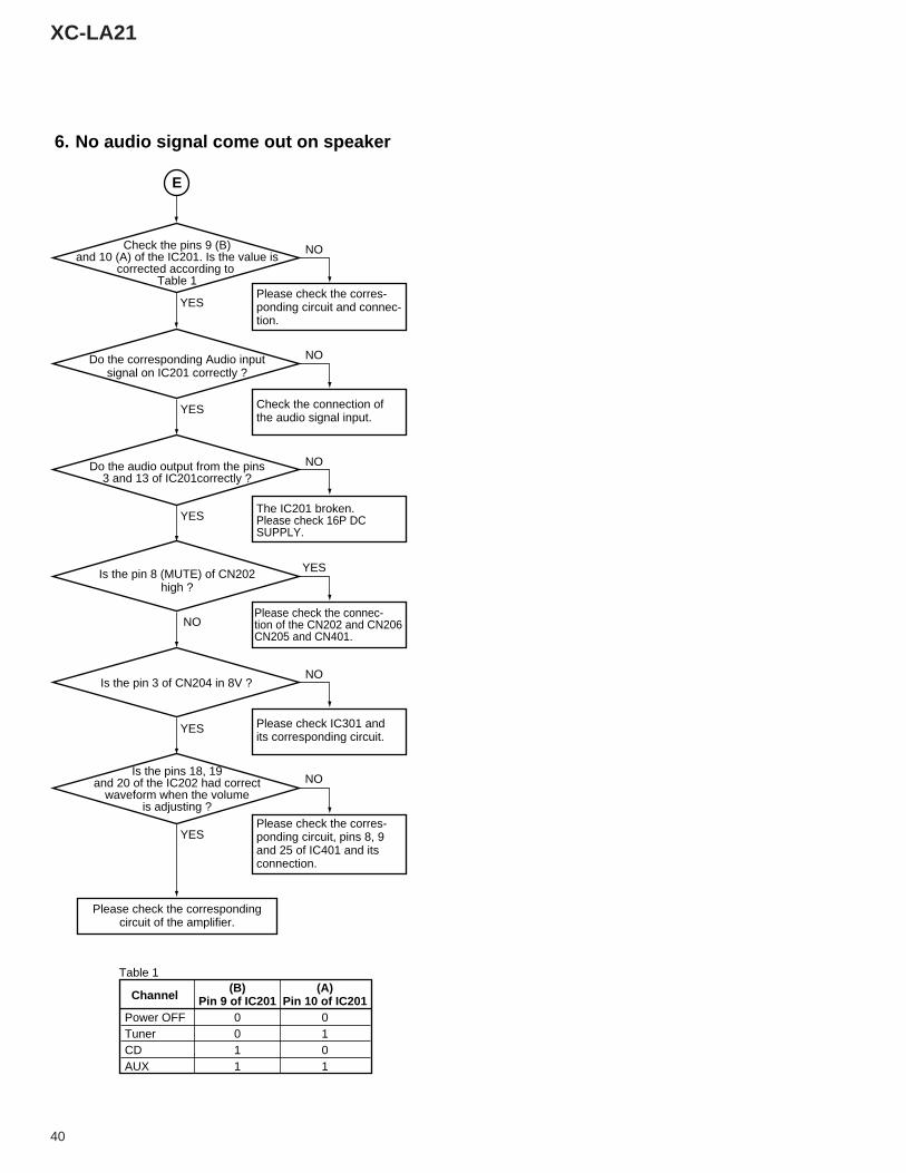
Please check the correspondingcircuit of the amplifier.
Please check the corres-ponding circuit and connec-tion.
Check the connection ofthe audio signal input.
The IC201 broken.Please check 16P DC SUPPLY.
Please check the connec-tion of the CN202 and CN206CN205 and CN401.
Please check the corres-ponding circuit, pins 8, 9and 25 of IC401 and itsconnection.
Please check IC301 andits corresponding circuit.
Check the pins 9 (B)and 10 (A) of the IC201. Is the value is
corrected according to Table 1
Is the pins 18, 19and 20 of the IC202 had correct
waveform when the volumeis adjusting ?
YES
YES
Do the corresponding Audio inputsignal on IC201 correctly ?
Do the audio output from the pins3 and 13 of IC201correctly ?
E
6. No audio signal come out on speaker
NO
NO
YES
NO
NO
Is the pin 8 (MUTE) of CN202high ?
YES
YES
NO
YES
NO
Is the pin 3 of CN204 in 8V ?
(B) (A) Channel Pin 9 of IC201 Pin 10 of IC201Power OFF 0 0Tuner 0 1CD 1 0AUX 1 1
Table 1
41
XC-LA21
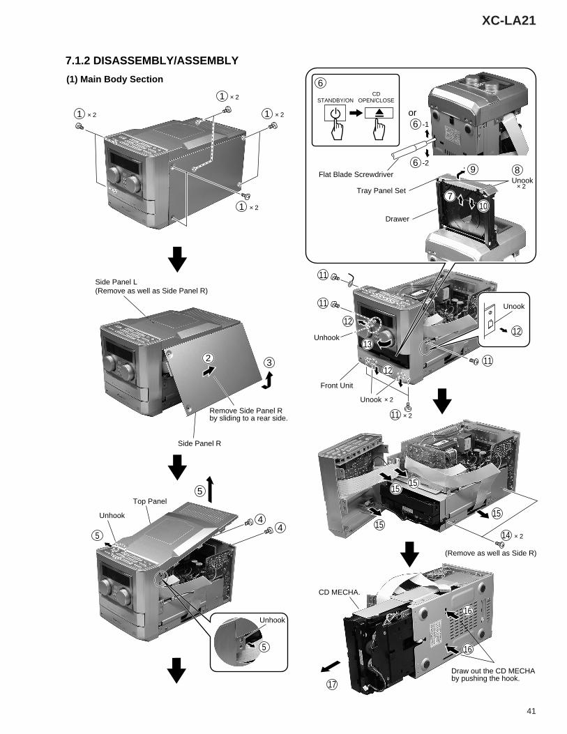
Unhook
Unook
12
12
Unook
× 21
× 21
× 21
× 2
× 211
× 2
4
6
6
7
5
2 3
× 21
Side Panel R
Front Unit
Remove Side Panel Rby sliding to a rear side.
Side Panel L(Remove as well as Side Panel R)
4
STANDBY/ON
or
CDOPEN/CLOSE
UnookTray Panel Set
Drawer
Flat Blade Screwdriver9
11
10
11
11
12
Unhook
5
Unhook
Top Panel
5
13
8
7.1.2 DISASSEMBLY/ASSEMBLY
(1) Main Body Section
× 214
1515
15
(Remove as well as Side R)
15
16
16
17
Draw out the CD MECHA by pushing the hook.
CD MECHA.
-2
6 -1
42
XC-LA21
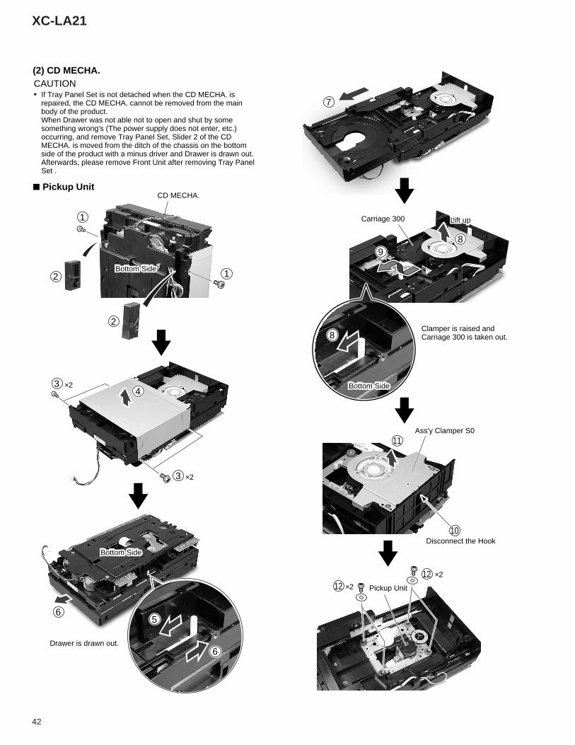
(2) CD MECHA.
7 Pickup Unit
CAUTION• If Tray Panel Set is not detached when the CD MECHA. is
repaired, the CD MECHA. cannot be removed from the main body of the product. When Drawer was not able not to open and shut by some something wrong's (The power supply does not enter, etc.) occurring, and remove Tray Panel Set, Slider 2 of the CD MECHA. is moved from the ditch of the chassis on the bottom side of the product with a minus driver and Drawer is drawn out. Afterwards, please remove Front Unit after removing Tray Panel Set .
1
2
2
34
3
1
CD MECHA.
Carriage 300
Ass'y Clamper S0
Bottom Side
Bottom Side×2
×2
×2
×2
5
6
6
Bottom Side
7
8
11
1212
9
8
Lift up
Disconnect the Hook
Pickup Unit
10
Drawer is drawn out.
Clamper is raised and Carriage 300 is taken out.
43
XC-LA21
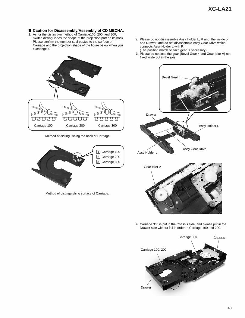
7 Caution for Disassembly/Assembly of CD MECHA. 1. As for the distinction method of Carriage100, 200, and 300,
Switch distinguishes the shape of the projection part on its back. Please confirm the number seal pasted to the surface of Carriage and the projection shape of the figure below when you exchange it.
2. Please do not disassemble Assy Holder L, R and the inside of and Drawer, and do not disassemble Assy Gear Drive which connects Assy Holder L with R. (The position match of each gear is necessary)
3. Please do not lose the gear (Bevel Gear 4 and Gear Idler A) not fixed while put in the axis.
Carriage 100
Method of distinguishing the back of Carriage.
Method of distinguishing surface of Carriage.
Carriage 200 Carriage 300
Carriage 1001
Carriage 2002
Carriage 3003
4. Carriage 300 is put in the Chassis side, and please put in the Drawer side without fail in order of Carriage 100 and 200.
Bevel Gear 4
Drawer
Assy Gear Drive
Assy Holder R
Assy Holder L
Gear Idler A
Carriage 100, 200
Carriage 300 Chassis
Drawer
44
XC-LA21
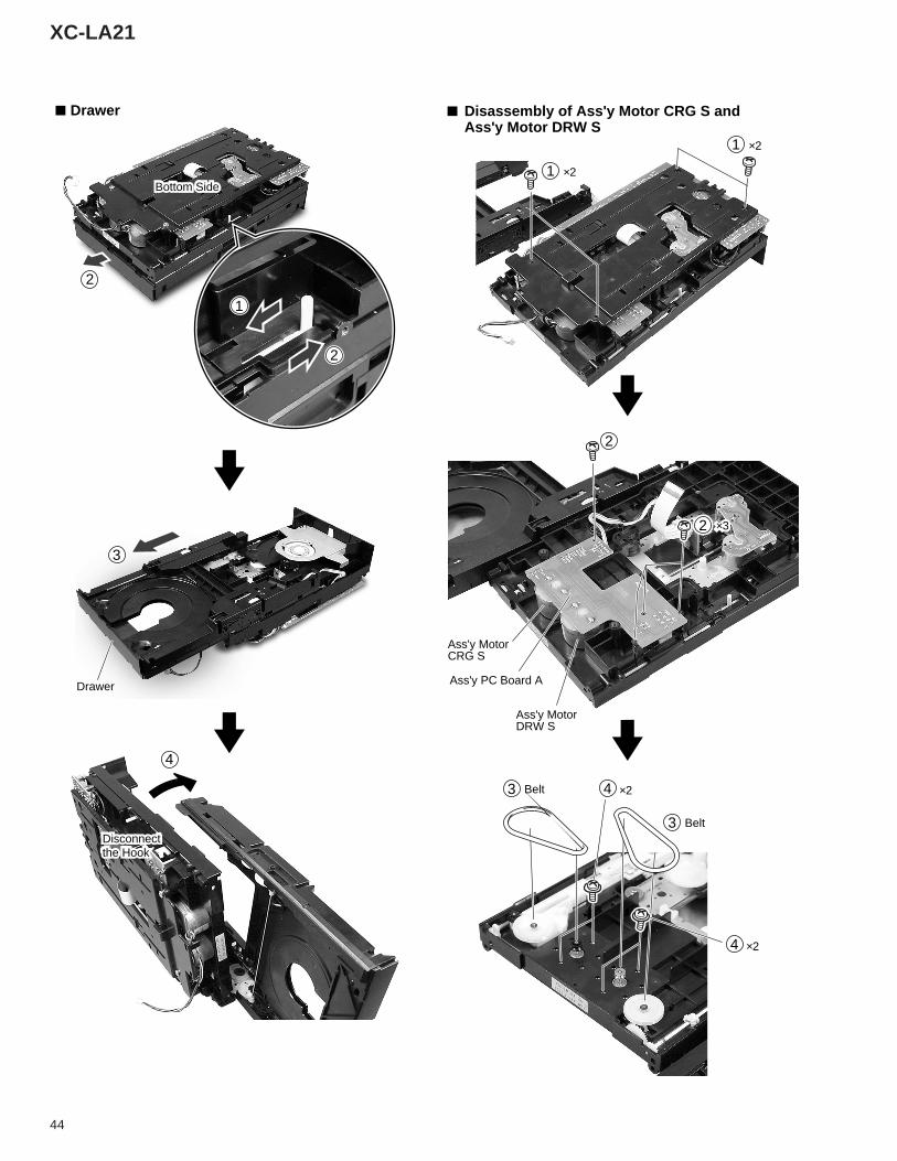
7 Drawer
1
2
4
2
Bottom Side
Disconnectthe Hook
3
7 Disassembly of Ass'y Motor CRG S andAss'y Motor DRW S
1
Ass'y PC Board A
Belt
Drawer
Ass'y MotorCRG S
Ass'y MotorDRW S
×2
×2
1 ×2
2
3
Belt3
4
×24
2
×3
45
XC-LA21
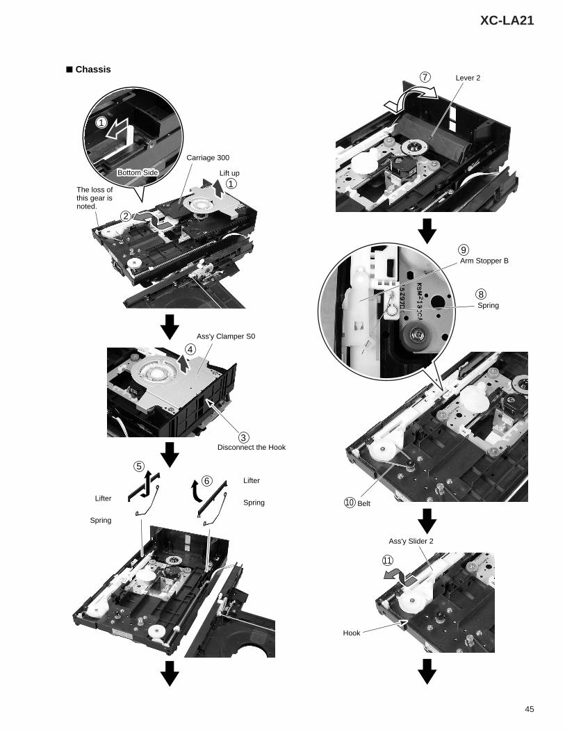
Lever 27
8
9
Spring
10
11
Belt
Arm Stopper B
Ass'y Slider 2
Hook
7 Chassis
Disconnect the Hook
Lifter
SpringLifter
Spring
5
6
Carriage 300
Ass'y Clamper S0
1
4
3
2
Lift upBottom Side
1
The loss of this gear is noted.
46
XC-LA21
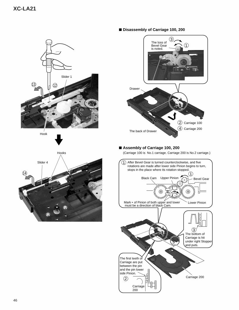
7 Disassembly of Carriage 100, 200
7 Assembly of Carriage 100, 200
2
3
1The loss of Bevel Gear is noted.
Drawer
The back of Drawer
Carriage 100
1
1
Bevel GearUpper PinionBlack Cam
Lower PinionMark • of Pinion of both upper and lower must be a direction of black Cam.
(Carriage 100 is No.1 carriage. Carriage 200 is No.2 carriage.)
After Bevel Gear is turned counterclockwise, and five rotations are made after lower side Pinion begins to turn, stops in the place where its rotation stopped.
4 Carriage 200
3The bottom of Carriage is hit under right Stopper and puts.
Carriage 2002
The first teeth of Carriage are put between the pin and the pin lower side Pinion.
Carriage200
1213
Hook
Slider 1
Slider 4
Hooks
14
47
XC-LA21
9
7
8 9
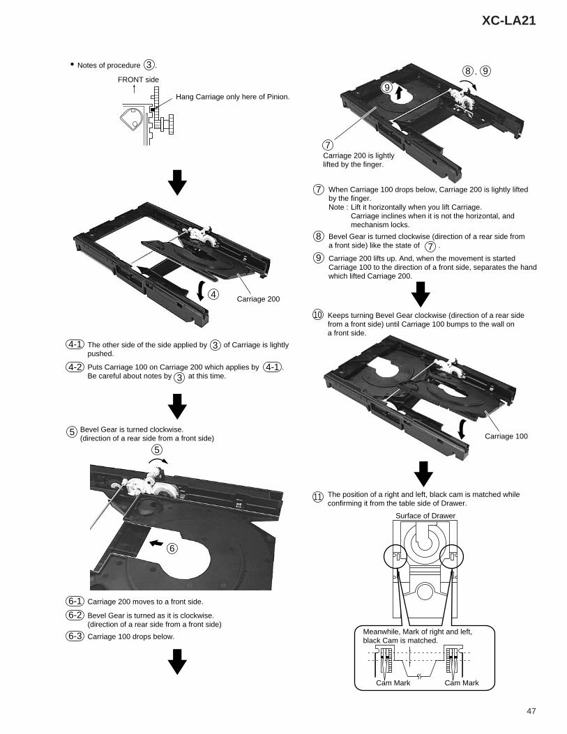
Carriage 200 is lightly lifted by the finger.
,
8
7
7
When Carriage 100 drops below, Carriage 200 is lightly lifted by the finger. Note : Lift it horizontally when you lift Carriage.
Carriage inclines when it is not the horizontal, and mechanism locks.
Bevel Gear is turned clockwise (direction of a rear side from a front side) like the state of .
9 Carriage 200 lifts up. And, when the movement is started Carriage 100 to the direction of a front side, separates the hand which lifted Carriage 200.
Carriage 100
Surface of Drawer
10
11
Keeps turning Bevel Gear clockwise (direction of a rear side from a front side) until Carriage 100 bumps to the wall on a front side.
11 The position of a right and left, black cam is matched while confirming it from the table side of Drawer.
Cam Mark Cam Mark
Meanwhile, Mark of right and left, black Cam is matched.
Bevel Gear is turned clockwise. (direction of a rear side from a front side)
3
3
Hang Carriage only here of Pinion.
FRONT side
• Notes of procedure .
4
3
5
5
6
Carriage 200
4-1
4-2 4-1Puts Carriage 100 on Carriage 200 which applies by . Be careful about notes by at this time.
The other side of the side applied by of Carriage is lightly pushed.
6-1 Carriage 200 moves to a front side.
6-3 Carriage 100 drops below.
6-2 Bevel Gear is turned as it is clockwise. (direction of a rear side from a front side)
48
XC-LA21
6
4
35
Bevel Gear
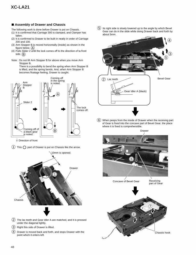
2 The lac teeth and Gear Idler A are matched, and it is pressed under the diagonal lightly.
3 Right this side of Drawer is lifted.
4 Drawer is moved back and forth, and stops Drawer with the point which it enters left.
5 Its right side is slowly lowered up to the angle by which Bevel Gear can do in the slide while doing Drawer back and forth by about 5mm.
Drawer
Chassis
10mm is opened.
Drawer
1
1 This part of Drawer is put on Chassis like the arrow.
The following work is done before Drawer is put on Chassis. (1) It is confirmed that Carriage 300 is clamped, and Clamper has
fallen. (2) It is confirmed to Drawer to be built in neatly in order of Carriage
200 and 100. (3) Arm Stopper B is moved horizontally (inside) as shown in the
figure below. (4) Pulls Slider 2 until the lock comes off to the direction of ta front
side.
7 Assembly of Drawer and Chassis
A
A
B
BComing off of a black gear is noted.
Coming off in the spring is noted.
The lock comes off.
Slider 2
Direction of front
ArmStopperB
Note : Do not lift Arm Stopper B for above when you move Arm Stopper B. There is a possibility to bend the spring when Arm Stopper B is lifted, and the spring bends. And, when Arm Stopper B becomes floatage feeling, Drawer is caught.
6
7
8
2 Lac teeth
Gear Idler A (black)
Receiving part of Gear
Concave of Bevel Gear
When peeps from the inside of Drawer when the receiving part of Gear is fixed into the concave part of Bevel Gear, the place where it is fixed is comprehensible.
Chassis hook
49
XC-LA21
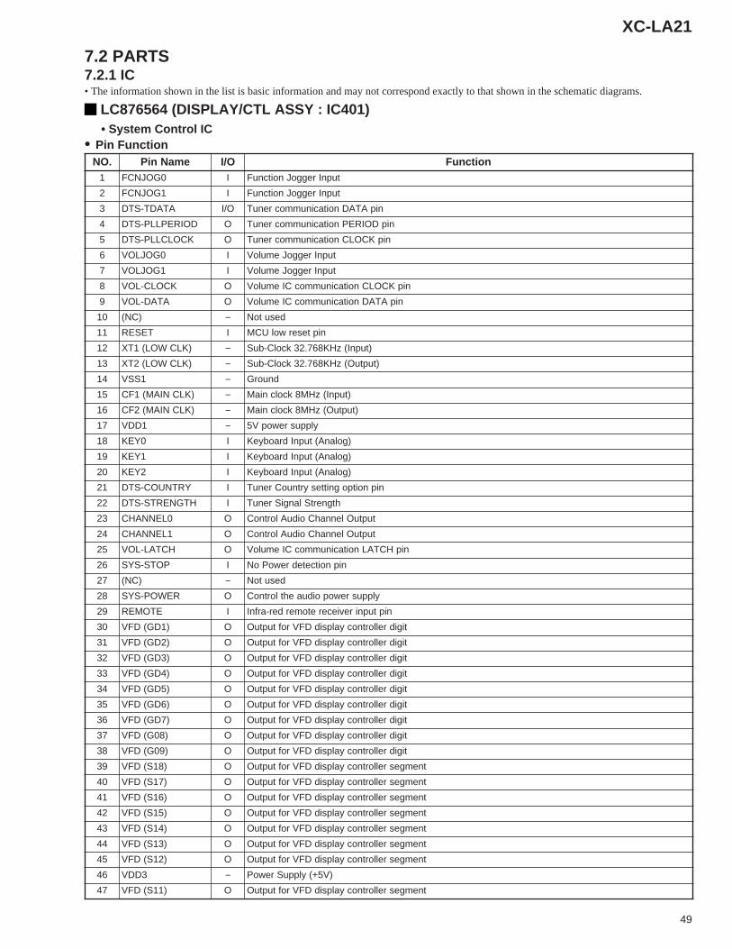
LC876564 (DISPLAY/CTL ASSY : IC401) • System Control IC• Pin Function
• The information shown in the list is basic information and may not correspond exactly to that shown in the schematic diagrams.
7.2 PARTS7.2.1 IC
.ON emaNniP O/I noitcnuF1 0GOJNCF I tupnIreggoJnoitcnuF
2 1GOJNCF I tupnIreggoJnoitcnuF
3 ATADT-STD O/I nipATADnoitacinummocrenuT
4 DOIREPLLP-STD O nipDOIREPnoitacinummocrenuT
5 KCOLCLLP-STD O nipKCOLCnoitacinummocrenuT
6 0GOJLOV I tupnIreggoJemuloV
7 1GOJLOV I tupnIreggoJemuloV
8 KCOLC-LOV O nipKCOLCnoitacinummocCIemuloV
9 ATAD-LOV O nipATADnoitacinummocCIemuloV
01 )CN( − desutoN
11 TESER I nipteserwolUCM
21 )KLCWOL(1TX − )tupnI(zHK867.23kcolC-buS
31 )KLCWOL(2TX − )tuptuO(zHK867.23kcolC-buS
41 1SSV − dnuorG
51 )KLCNIAM(1FC − )tupnI(zHM8kcolcniaM
61 )KLCNIAM(2FC − )tuptuO(zHM8kcolcniaM
71 1DDV − ylppusrewopV5
81 0YEK I )golanA(tupnIdraobyeK
91 1YEK I )golanA(tupnIdraobyeK
02 2YEK I )golanA(tupnIdraobyeK
12 YRTNUOC-STD I nipnoitpognittesyrtnuoCrenuT
22 HTGNERTS-STD I htgnertSlangiSrenuT
32 0LENNAHC O tuptuOlennahCoiduAlortnoC
42 1LENNAHC O tuptuOlennahCoiduAlortnoC
52 HCTAL-LOV O nipHCTALnoitacinummocCIemuloV
62 POTS-SYS I nipnoitcetedrewoPoN
72 )CN( − desutoN
82 REWOP-SYS O ylppusrewopoiduaehtlortnoC
92 ETOMER I niptupnirevieceretomerder-arfnI
03 )1DG(DFV O tigidrellortnocyalpsidDFVroftuptuO
13 )2DG(DFV O tigidrellortnocyalpsidDFVroftuptuO
23 )3DG(DFV O tigidrellortnocyalpsidDFVroftuptuO
33 )4DG(DFV O tigidrellortnocyalpsidDFVroftuptuO
43 )5DG(DFV O tigidrellortnocyalpsidDFVroftuptuO
53 )6DG(DFV O tigidrellortnocyalpsidDFVroftuptuO
63 )7DG(DFV O tigidrellortnocyalpsidDFVroftuptuO
73 )80G(DFV O tigidrellortnocyalpsidDFVroftuptuO
83 )90G(DFV O tigidrellortnocyalpsidDFVroftuptuO
93 )81S(DFV O tnemgesrellortnocyalpsidDFVroftuptuO
04 )71S(DFV O tnemgesrellortnocyalpsidDFVroftuptuO
14 )61S(DFV O tnemgesrellortnocyalpsidDFVroftuptuO
24 )51S(DFV O tnemgesrellortnocyalpsidDFVroftuptuO
34 )41S(DFV O tnemgesrellortnocyalpsidDFVroftuptuO
44 )31S(DFV O tnemgesrellortnocyalpsidDFVroftuptuO
54 )21S(DFV O tnemgesrellortnocyalpsidDFVroftuptuO
64 3DDV − )V5+(ylppuSrewoP
74 )11S(DFV O tnemgesrellortnocyalpsidDFVroftuptuO
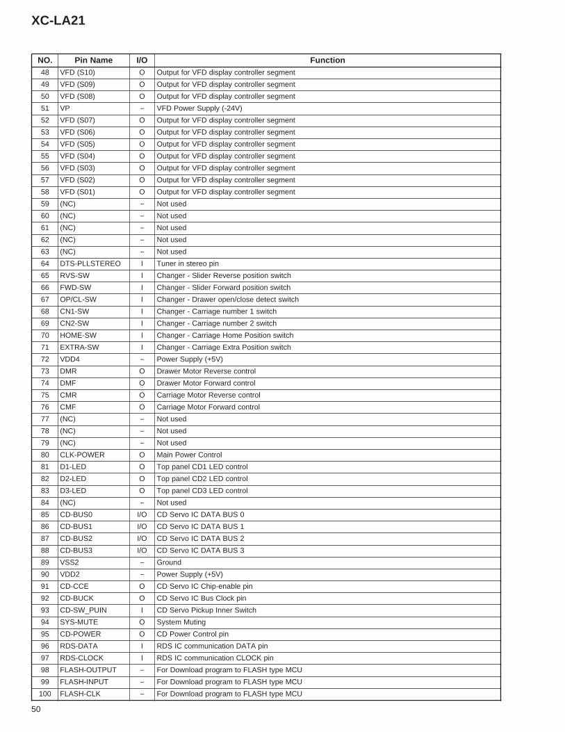
50
XC-LA21
.ON emaNniP O/I noitcnuF84 )01S(DFV O tnemgesrellortnocyalpsidDFVroftuptuO
94 )90S(DFV O tnemgesrellortnocyalpsidDFVroftuptuO
05 )80S(DFV O tnemgesrellortnocyalpsidDFVroftuptuO
15 PV − )V42-(ylppuSrewoPDFV
25 )70S(DFV O tnemgesrellortnocyalpsidDFVroftuptuO
35 )60S(DFV O tnemgesrellortnocyalpsidDFVroftuptuO
45 )50S(DFV O tnemgesrellortnocyalpsidDFVroftuptuO
55 )40S(DFV O tnemgesrellortnocyalpsidDFVroftuptuO
65 )30S(DFV O tnemgesrellortnocyalpsidDFVroftuptuO
75 )20S(DFV O tnemgesrellortnocyalpsidDFVroftuptuO
85 )10S(DFV O tnemgesrellortnocyalpsidDFVroftuptuO
95 )CN( − desutoN
06 )CN( − desutoN
16 )CN( − desutoN
26 )CN( − desutoN
36 )CN( − desutoN
46 OERETSLLP-STD I nipoeretsnirenuT
56 WS-SVR I hctiwsnoitisopesreveRredilS-regnahC
66 WS-DWF I hctiwsnoitisopdrawroFredilS-regnahC
76 WS-LC/PO I hctiwstcetedesolc/neporewarD-regnahC
86 WS-1NC I hctiws1rebmunegairraC-regnahC
96 WS-2NC I hctiws2rebmunegairraC-regnahC
07 WS-EMOH I hctiwsnoitisoPemoHegairraC-regnahC
17 WS-ARTXE I hctiwsnoitisoPartxEegairraC-regnahC
27 4DDV − )V5+(ylppuSrewoP
37 RMD O lortnocesreveRrotoMrewarD
47 FMD O lortnocdrawroFrotoMrewarD
57 RMC O lortnocesreveRrotoMegairraC
67 FMC O lortnocdrawroFrotoMegairraC
77 )CN( − desutoN
87 )CN( − desutoN
97 )CN( − desutoN
08 REWOP-KLC O lortnoCrewoPniaM
18 DEL-1D O lortnocDEL1DClenappoT
28 DEL-2D O lortnocDEL2DClenappoT
38 DEL-3D O lortnocDEL3DClenappoT
48 )CN( − desutoN
58 0SUB-DC O/I 0SUBATADCIovreSDC
68 1SUB-DC O/I 1SUBATADCIovreSDC
78 2SUB-DC O/I 2SUBATADCIovreSDC
88 3SUB-DC O/I 3SUBATADCIovreSDC
98 2SSV − dnuorG
09 2DDV − )V5+(ylppuSrewoP
19 ECC-DC O nipelbane-pihCCIovreSDC
29 KCUB-DC O nipkcolCsuBCIovreSDC
39 NIUP_WS-DC I hctiwSrennIpukciPovreSDC
49 ETUM-SYS O gnituMmetsyS
59 REWOP-DC O niplortnoCrewoPDC
69 ATAD-SDR I nipATADnoitacinummocCISDR
79 KCOLC-SDR I nipKCOLCnoitacinummocCISDR
89 TUPTUO-HSALF − UCMepytHSALFotmargorpdaolnwoDroF
99 TUPNI-HSALF − UCMepytHSALFotmargorpdaolnwoDroF
001 KLC-HSALF − UCMepytHSALFotmargorpdaolnwoDroF
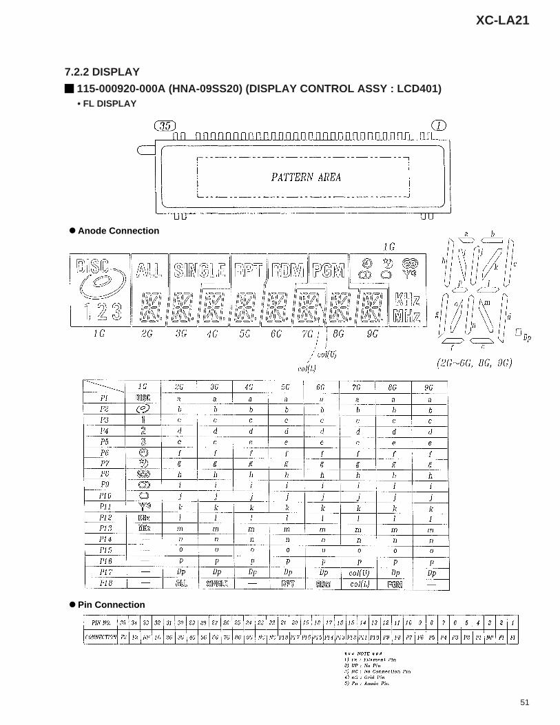
51
XC-LA21
115-000920-000A (HNA-09SS20) (DISPLAY CONTROL ASSY : LCD401) • FL DISPLAY
7.2.2 DISPLAY
Anode Connection
Pin Connection
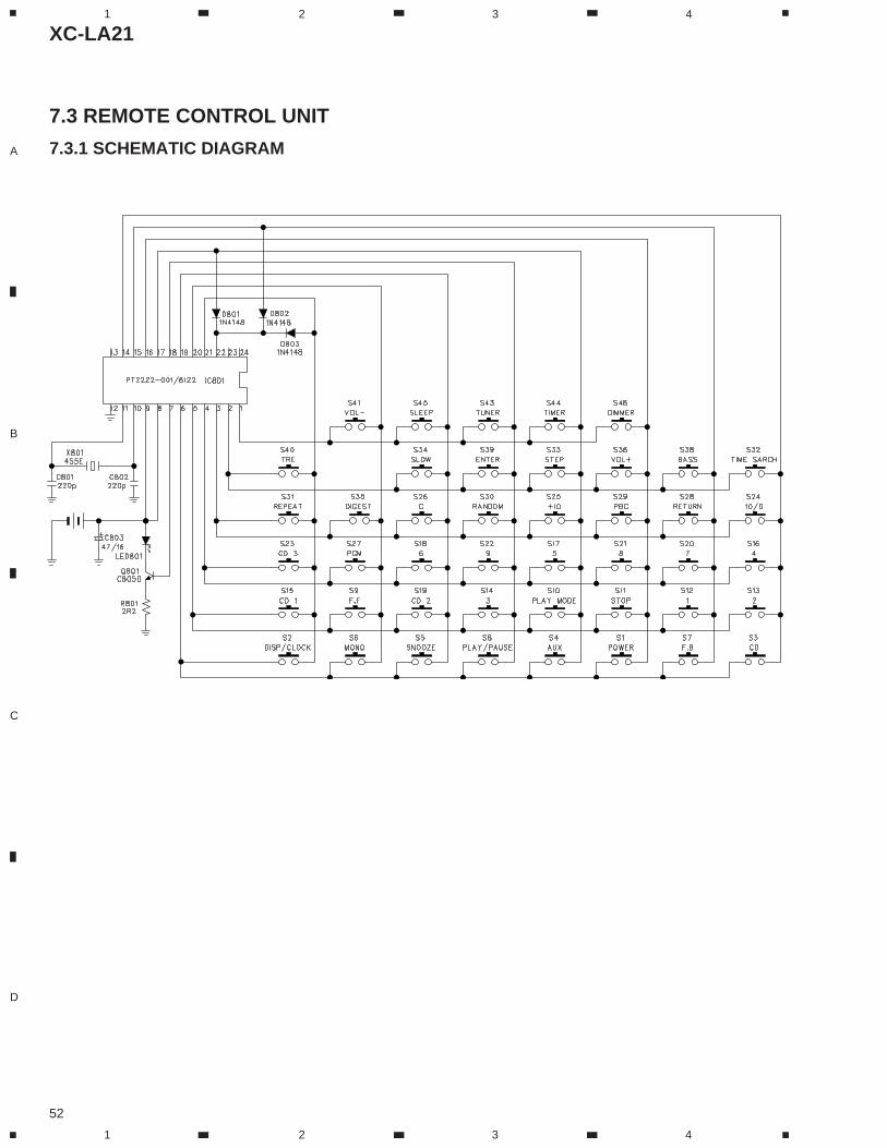
XC-LA21
52
A
B
C
D
1 2 3 4
1 2 3 4
7.3 REMOTE CONTROL UNIT
7.3.1 SCHEMATIC DIAGRAM
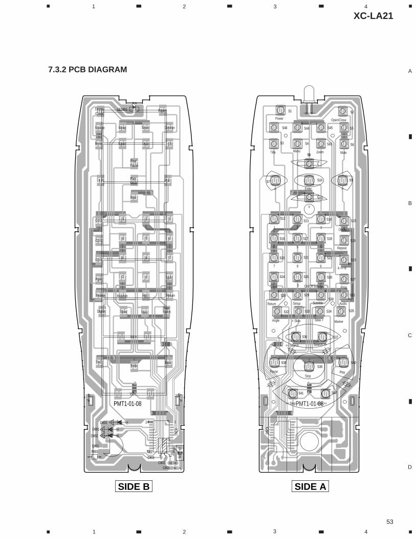
XC-LA21
53
A
B
C
D
1 2 3 4
1 2 3 4
7.3.2 PCB DIAGRAM
PMT1-01-08
S46 S45S44
S43
S42S41
S40S39
S38
S37S36
S35S34S33S32
S31S30
S29S28
S27S26S25S24
S20 S21 S22 S23
S19S18S17S16
S15S14S13S12
S11
S9S7 S10
S8
S6
S5
S4S3
S2S1
Skip >><< Skip
PlayPauseStop
Search >><< Search
MarkerSlow >< SlowAngle
SubtiitleSetupReturn
On/Off Subtitle0Clear
Audio
Prog
A <> B
Repeat
Disply
987
654
321
V
Enter -><-
V
MuteZoomMenuTitle
Open/ClosePower
IC801
24
1312
1
IC801
Vol -
Tre BassEnter
Vol +
TimeDigest Slow Step Sarch
Repeat ReturnPBCRandom
PgmC 0 10/0
789CD 3
CD 2 6 5 4
CD 1 3 2 1
Mode
Play/
F.BF.F
Stop
Play
Pause
Mono Tuner Aux CD
Snooze Sleep Timer Dimmer
/ClockDisplay Power
B+B-
D803
D801
D802
C801C802
X801
R801
C803
Q801
LED801
PMT1-01-08
SIDE ASIDE B
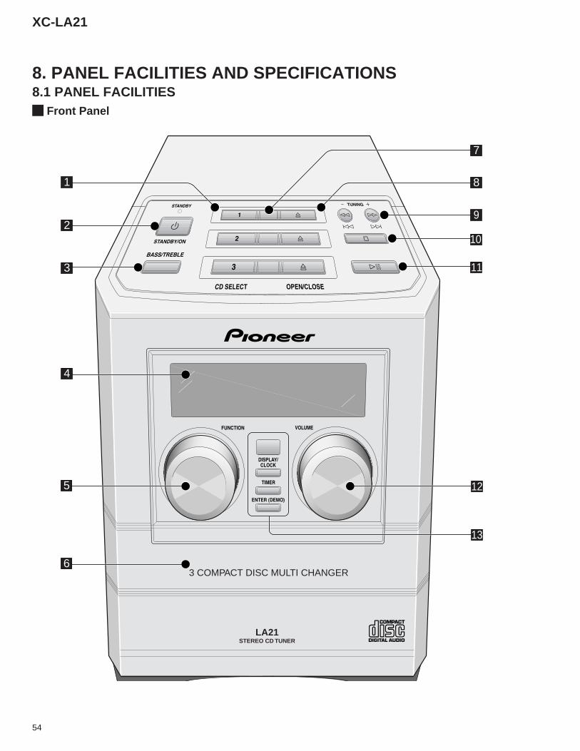
54
XC-LA21
8.1 PANEL FACILITIES8. PANEL FACILITIES AND SPECIFICATIONS
Front Panel
LA21
3 COMPACT DISC MULTI CHANGER
STEREO CD TUNER
1
2
3
4
5
6
8
9
7
10
11
12
13
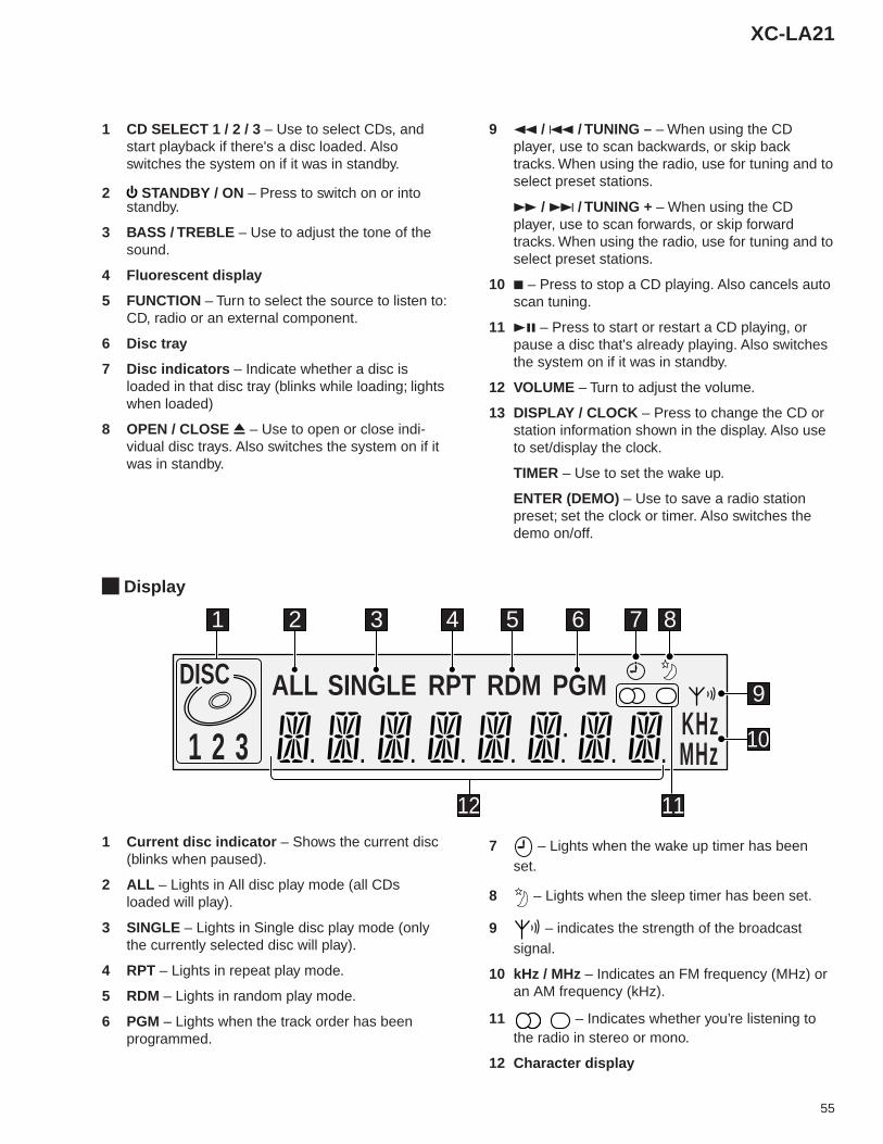
55
XC-LA21
Display
ALL SINGLE RPT RDM PGMDISC
1 2 3KHzMHz
1 2 3 4 5 6 7 8
9
10
11121 Current disc indicator – Shows the current disc
(blinks when paused).
2 ALL – Lights in All disc play mode (all CDsloaded will play).
3 SINGLE – Lights in Single disc play mode (onlythe currently selected disc will play).
4 RPT – Lights in repeat play mode.
5 RDM – Lights in random play mode.
6 PGM – Lights when the track order has beenprogrammed.
7 – Lights when the wake up timer has beenset.
8 – Lights when the sleep timer has been set.
9 – indicates the strength of the broadcastsignal.
10 kHz / MHz – Indicates an FM frequency (MHz) oran AM frequency (kHz).
11 – Indicates whether you’re listening tothe radio in stereo or mono.
12 Character display
1 CD SELECT 1 / 2 / 3 – Use to select CDs, andstart playback if there's a disc loaded. Alsoswitches the system on if it was in standby.
2 STANDBY / ON – Press to switch on or intostandby.
3 BASS / TREBLE – Use to adjust the tone of thesound.
4 Fluorescent display
5 FUNCTION – Turn to select the source to listen to:CD, radio or an external component.
6 Disc tray
7 Disc indicators – Indicate whether a disc isloaded in that disc tray (blinks while loading; lightswhen loaded)
8 OPEN / CLOSE 0 – Use to open or close indi-vidual disc trays. Also switches the system on if itwas in standby.
9 1 / 4 / TUNING – – When using the CDplayer, use to scan backwards, or skip backtracks. When using the radio, use for tuning and toselect preset stations.
¡ / ¢ / TUNING + – When using the CDplayer, use to scan forwards, or skip forwardtracks. When using the radio, use for tuning and toselect preset stations.
10 7 – Press to stop a CD playing. Also cancels autoscan tuning.
11 38 – Press to start or restart a CD playing, orpause a disc that's already playing. Also switchesthe system on if it was in standby.
12 VOLUME – Turn to adjust the volume.
13 DISPLAY / CLOCK – Press to change the CD orstation information shown in the display. Also useto set/display the clock.
TIMER – Use to set the wake up.
ENTER (DEMO) – Use to save a radio stationpreset; set the clock or timer. Also switches thedemo on/off.
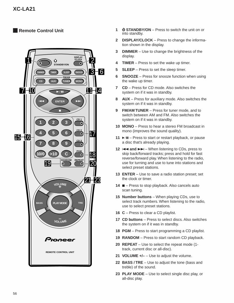
56
XC-LA21
Remote Control Unit 1 STANDBY/ON – Press to switch the unit on orinto standby.
2 DISPLAY/CLOCK – Press to change the informa-tion shown in the display.
3 DIMMER – Use to change the brightness of thedisplay.
4 TIMER – Press to set the wake up timer.
5 SLEEP – Press to set the sleep timer.
6 SNOOZE – Press for snooze function when usingthe wake up timer.
7 CD – Press for CD mode. Also switches thesystem on if it was in standby.
8 AUX – Press for auxiliary mode. Also switches thesystem on if it was in standby.
9 FM/AM TUNER – Press for tuner mode, and toswitch between AM and FM. Also switches thesystem on if it was in standby.
10 MONO – Press to hear a stereo FM broadcast inmono (improves the sound quality).
11 6 – Press to start or restart playback, or pausea disc that’s already playing.
12 4 and ¢ – When listening to CDs, press toskip back/forward tracks; press and hold for fastreverse/forward play. When listening to the radio,use for turning and use to tune into stations andselect preset stations.
13 ENTER – Use to save a radio station preset; setthe clock or timer.
14 7 – Press to stop playback. Also cancels autoscan tuning.
15 Number buttons – When playing CDs, use toselect track numbers. When listening to the radio,use to select preset stations.
16 C – Press to clear a CD playlist.
17 CD buttons – Press to select discs. Also switchesthe system on if it was in standby.
18 PGM – Press to start programming a CD playlist.
19 RANDOM – Press to start random CD playback.
20 REPEAT – Use to select the repeat mode (1-track, current disc or all-disc).
21 VOLUME +/– – Use to adjust the volume.
22 BASS / TRE – Use to adjust the tone (bass andtreble) of the sound.
23 PLAY MODE – Use to select single disc play, orall-disc play.
ENTER
BASS TRE
RANDOM REPEAT
PGM
CD 3
CD 2
CD 1
MONOTUNER
FM/AM
AUXCD
DISPLAY/CLOCK
SNOOZESLEEPTIMERDIMMER
1 2 3
4 5 6
7 8 9
10/0 >10 C
PLAY MODE
STANDBY/ON
4 ¢
7
6
VOLUME
VOLUME
+
–
REMOTE CONTROL UNIT
6
7 10
1 2
21 23
3
1819 20
11 14
15 16 17
–
–
–
–
–
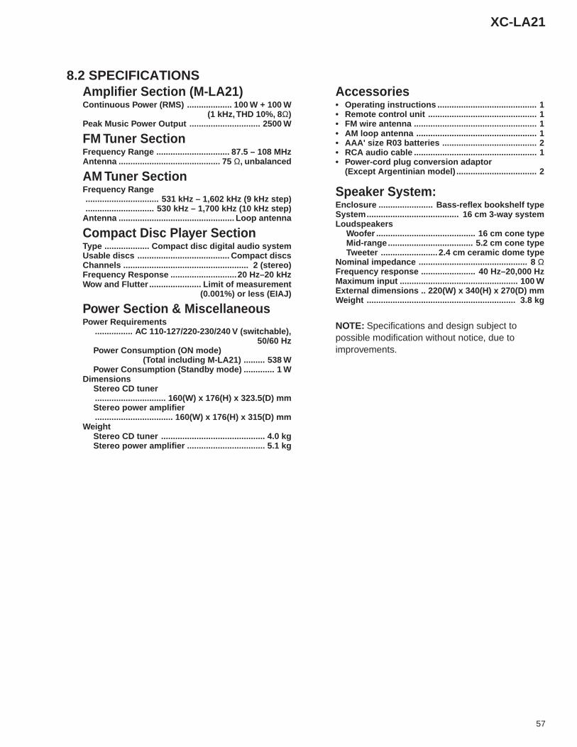
57
XC-LA21
8.2 SPECIFICATIONSAmplifier Section (M-LA21)Continuous Power (RMS) ................... 100 W + 100 W
(1 kHz, THD 10%, 8Ω)Peak Music Power Output .............................. 2500 W
FM Tuner SectionFrequency Range ............................... 87.5 – 108 MHzAntenna ........................................... 75 Ω, unbalanced
AM Tuner SectionFrequency Range............................... 531 kHz – 1,602 kHz (9 kHz step)............................. 530 kHz – 1,700 kHz (10 kHz step)
Antenna ................................................. Loop antenna
Compact Disc Player SectionType ................... Compact disc digital audio systemUsable discs ....................................... Compact discsChannels ..................................................... 2 (stereo)Frequency Response ............................20 Hz–20 kHzWow and Flutter ...................... Limit of measurement
(0.001%) or less (EIAJ)
Power Section & MiscellaneousPower Requirements
................ AC 110-127/220-230/240 V (switchable),50/60 Hz
Power Consumption (ON mode) (Total including M-LA21) ......... 538 WPower Consumption (Standby mode) ............. 1 W
DimensionsStereo CD tuner.............................. 160(W) x 176(H) x 323.5(D) mmStereo power amplifier................................. 160(W) x 176(H) x 315(D) mm
WeightStereo CD tuner ............................................ 4.0 kgStereo power amplifier ................................. 5.1 kg
Accessories• Operating instructions .......................................... 1• Remote control unit .............................................. 1• FM wire antenna .................................................... 1• AM loop antenna ................................................... 1• AAA' size R03 batteries ........................................ 2• RCA audio cable .................................................... 1• Power-cord plug conversion adaptor
(Except Argentinian model) .................................. 2
Speaker System:Enclosure ....................... Bass-reflex bookshelf typeSystem....................................... 16 cm 3-way systemLoudspeakers
Woofer .......................................... 16 cm cone typeMid-range .................................... 5.2 cm cone typeTweeter ........................ 2.4 cm ceramic dome type
Nominal impedance .............................................. 8 ΩFrequency response ....................... 40 Hz–20,000 HzMaximum input .................................................. 100 WExternal dimensions .. 220(W) x 340(H) x 270(D) mmWeight ............................................................... 3.8 kg
NOTE: Specifications and design subject topossible modification without notice, due toimprovements.


![3727].pdf · Elite FM Stereo Tuner Stereo Pre-Amplifier CDP CD Pre-Amplifier CDS Compact Disc Player Owner's Manual](https://img.pdfslide.net/doc/110x75/5bb5abea09d3f2b63a8d384c/3727pdf-elite-fm-stereo-tuner-stereo-pre-amplifier-cdp-cd-pre-amplifier-cds.jpg)