Embed Size (px)
Citation preview
Copyright (c) 2013 IEEE. Personal use is permitted. For any other purposes, permission must be obtained from the IEEE by emailing [email protected].
This article has been accepted for publication in a future issue of this journal, but has not been fully edited. Content may change prior to final publication.
TBME-01982-2012
Abstract—This paper presents a novel MR-compatible 3-DOFcardiac catheter steering mechanism. The catheter’s steerablestructure is tendon driven and consists of miniature deflectable,helical segments created by a precise rapid prototypingtechnique. The created catheter prototype has an outer diameterof 9 Fr (3 mm) and a steerable distal end that can be deflected in3D space via four braided high-tensile Spectra® fiber tendons.Any longitudinal twist commonly observed in helical structures iscompensated for by employing clockwise (CW) and counterclockwise (CCW) helical segments in an alternating fashion. A280 µm flexible carbon fiber rod is used as a backbone in acentral channel to improve the structure’s steering andpositioning repeatability. In addition to the backbone, a carbonfiber tube can be inserted into the structure to a varying amountcapable of changing the structure’s forcibility and, thus,providing a means to change the curvature and to modify thedeflectable length of the catheter leading to an extension ofreachable points in the catheter-tip workspace. A unique featureof this helical segment structure is that the stiffness can befurther adjusted by appropriately tensioning tendonssimultaneously. An experimental study has been conductedexamining the catheter-tip trajectory in 3D space and itspositioning repeatability using a 5-DOF magnetic coil trackingsystem. Furthermore, MRI experiments in a 1.5 Tesla scannerconfirmed the MR-compatibility of the catheter prototype. Thestudy shows that the proposed concept for catheter steering hasgreat potential to be employed for robotically steered and MR-guided cardiac catheterization.
I. INTRODUCTION
ARDIAC catheterization is a minimally invasive procedureperformed by inserting a catheter tube through a smallincision into the femoral vein and advancing the catheter
through the vein into the heart. During this interventionalprocedure, the goal is to reach specific locations inside the
heart and to perform examinations or treatments, such aselectro-physical studies or radio frequency (RF) ablation ofcardiac arrhythmia. The number of degrees of freedom (DOF)for a standard catheter is limited as it can only rotate and slidethrough the punctured point in the artery [1], [2]. Mostcommercial catheters consists of a flexible plastic body and amaneuverable tip that is manipulated using pre-configuredguide-wires and a single tendon [3],[4] allowing a deflectionof the catheter tip in one direction only. Using concentriccombination of precurved elastic tubes has improved themanoeuvrability of the ore-configured catheters by increasingthe number of degrees of freedom and controllability [5].More advanced steering concepts have been proposed byindustry [6]-[8] and a number of commercial products such as,the Artisan ExtendTM Control Catheter allowing theadjustment of its tip position in three dimensions using 4tendons have been developed recently [19]. Until recently, theintegration of additional functionality came at the cost of alarger outer diameter (e.g. Hansen Medical’s Artisan cathetersystem which has an outer diameter of 11.5 Fr) and the needfor a metallic steering shaft to ensure sufficient catheterrigidity [9].Cardiac catheterization is usually guided using X-rayfluoroscopy to visualize the device inside a patient’s body.Despite the high temporal and spatial resolution of X-rayfluoroscopy, it can provide images with poor soft tissuecontrasts of the anatomy. In addition, the patient and medicalstaff are exposed to hazardous x-ray radiation [10]-[12], whichcan become an issue in complex procedures requiring longexposure time. During the last decade many efforts have been
3-DOF MR-Compatible Multi-Segment CardiacCatheter Steering Mechanism
Asghar Ataollahi*, Rashed Karim, Arash Soleiman Fallah, Kawal Rhode , Reza Razavi, Lakmal D.Seneviratne, Member, IEEE, Tobias Schaeffter, Kaspar Althoefer, Member, IEEE
C
Fig. 1. The prototype steerable mechanism.
This work was supported in part by Wellcome Trust and EPSRC underGrant WT088641/Z/09/Z.
A. Ataollahi, A. Soeliman Fallah, and K. Althoefer are with Centre forRobotics Research (CoRe), Department of Informatics, King’s CollegeLondon, Strand, London WC2R 2LS, U.K. (e-mail: [email protected];[email protected]; [email protected])
R. Karim, T. Schaeffter, R. Razavi, and K. Rhode, are with the Divisionof Imaging Scieneces, Department of Biomedical Engineering, King’sCollege London, London, SE1 7EH, UK. ([email protected];[email protected]; [email protected]; [email protected])
L.D. Seneviratne is with Centre for Robotics Research (CoRe),Department of Informatics, King’s College London, Strand, London WC2R2LS, U.K. and the College of Engineering, Khalifa University of Science,Technology & Research (KUSTAR), Abu Dhabi, U.A.E. (e-mail:[email protected])
Copyright (c) 2013 IEEE. Personal use is permitted. For any other purposes, permission must be obtained from the IEEE by emailing [email protected].
This article has been accepted for publication in a future issue of this journal, but has not been fully edited. Content may change prior to final publication.
TBME-01982-2012
undertaken to advance the field of Magnetic ResonanceImaging (MRI) towards image-guided interventions [13] andfirst clinical applications have been demonstrated [10]. Incontrast to x-ray, MRI avoids ionizing radiation, offersexcellent soft-tissue contrast and the ability to obtainanatomical as well as quantitative physiological information.Examples of procedures that will benefit from a MR-guidedapproach include treatments for congenital heart disease [14]and electrophysiology (EP) procedures [15]. However, themain roadblock for a widespread clinical use of MR-guidedinterventions is the limited number of MR-compatible devices[16]. Materials suitable for x-ray fluoroscopy are notnecessarily compatible with MRI scanners. Manyferromagnetic materials cannot be used in the MR-environment due to the generation of significant artifacts thatcan deteriorate the MR signal considerably. Furthermore,conductive wires which are usually used for steering and toenforce mechanical stability, can result in excessive heatingduring RF transmission [17]. Recently, novel concepts havebeen integrated into a electrophysiology catheter and MR-safety has been demonstrated [18]; However, the steerabilityof the developed device was limited. To the best knowledge ofthe authors, the proposed catheter steering concept is the firstof its kind, providing 3-DOF steerability in a catheter tip assmall as 9 Fr, whilst, in addition, achieving MR compatibility.
II. CATHETER DESIGN
The following functional requirements are considered forthe proposed catheter steering mechanism to be used forcardiac catheterization procedures.
1) MR-compatibility: Ferromagnetic material should beavoided to ensure MR-safety and diagnostic imagequality. Furthermore long conductive wires cannot beemployed in mechanical structure, since those wouldpotentially lead to excessive RF-heating.
2) Diameter: Desired diameter of the catheter should bebetween 7 and 10 Fr (2.3 mm to 3.3 mm).
3) Flexibility: The steerable section of the catheter shouldbe flexible enough to avoid possible injuries of vesselwall.
4) Stiffness: Adjustability of stiffness can help in EP-procedures to ensure providing adequate contact forceof the catheter tip with endocardium.
5) Maneuverability: The mechanism should provideefficient and accurate steering of the catheter tip to awide range of points inside the heart, without the needof twisting the catheter shaft.
6) Repeatability: Accurate relocation of the catheter-tip toreach a position in 3D space should be ensured.
7) Control technique: The catheter steering mechanismshould be designed to be adoptable to both robotic andmanual actuation systems.
8) Costs: A low-cost disposable steering mechanism isanother important objective, as it will avoid sterilizationissues and aid commercialization.
The work described here attempts to achieve the aboverequirements as much as possible. One of the main challengeswas to meet many requirements without the use of metalliccomponents, which are usually employed for mechanicalstability and steerability. The proposed catheter steeringmechanism consists of multiple stacked segments capable ofdeflecting along two axes. In addition, a sliding carbon fibertube is employed to modify the curvature radius adding anadditional degree of freedom. This is because of the lessflexibility of the carbon fiber tube which blocks a number ofsegments from being deflected as a result of tendon actuation.The aim of the carbon fiber tube is to improve the catheter-tipnavigation and enhance the tip force by providing support forthe flexible manipulator. Stiffness adjustability is an additionalfeature of our design.
A. Segment Design
The presented catheter steering structure is made ofmultiple segments stacked together to shape a long steerablecatheter tip (see Fig.1). Each segment, as shown in Fig. 2, hasa helical structure with a length of 9 mm. The outer diameterof each segment is 9 Fr (3 mm) and the inside lumen has aninner diameter of 1.7 mm allowing the insertion of otheroptional elements. Each segment has three complete helicalturns with a helical pitch of 1.55 mm and spring gap of 0.45
Fig. 2. (a) Schematic view of a clockwise (CW) segment. (b) Schematic viewof a counter clockwise (CCW) segment. (c) Cross section view of a segment.(d) Bottom view (left) and top view (right) of a segment.
Copyright (c) 2013 IEEE. Personal use is permitted. For any other purposes, permission must be obtained from the IEEE by emailing [email protected].
This article has been accepted for publication in a future issue of this journal, but has not been fully edited. Content may change prior to final publication.
TBME-01982-2012
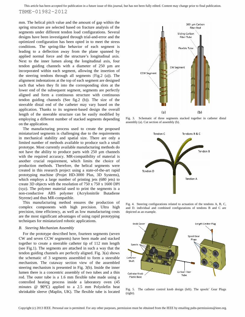
mm. The helical pitch value and the amount of gap within thespring structure are selected based on fracture analysis of thesegments under different tendon load configurations. Severaldesigns have been investigated through trial-and-error and theoptimized configuration has been opted in to meet the stressconditions. The spring-like behavior of each segment isleading to a deflection away from the plane spanned byapplied normal force and the structure’s longitudinal axis.Next to the inner lumen along the longitudinal axis, fourtendon guiding channels with a diameter of 250 µm areincorporated within each segment, allowing the insertion ofthe steering tendons through all segments (Fig.2 (a)). Thealignment indentations at the top of each segment are designedsuch that when they fit into the corresponding slots at thelower end of the subsequent segment, segments are perfectlyaligned and form a continuous structure with continuoustendon guiding channels (See fig.2 (b)). The size of thesteerable distal end of the catheter may vary based on theapplication. Thanks to its segment-based design the overalllength of the steerable structure can be easily modified byemploying a different number of stacked segments dependingon the application.
The manufacturing process used to create the proposedminiaturized segments is challenging due to the requirementsin mechanical stability and spatial size. There are only alimited number of methods available to produce such a smallprototype. Most currently available manufacturing methods donot have the ability to produce parts with 250 µm channelswith the required accuracy. MR-compatibility of material isanother crucial requirement, which limits the choice ofproduction methods. Therefore, the helical segments werecreated in this research project using a state-of-the-art rapidprototyping machine (Projet HD-3000 Plus, 3D Systems),which employs a large number of printing jets (680 jets) tocreate 3D objects with the resolution of 750 x 750 x 1600 DPI(xyz). The polymer material used to print the segments is anon-conductive ABS polymer (Acrylonitrile ButadieneStyrene) and thus MR-compatible.
This manufacturing method ensures the production ofcomplex components with high precision. Ultra highprecision, time efficiency, as well as low manufacturing costsare the most significant advantages of using rapid prototypingtechniques for miniaturized robotic applications.
B. Steering Mechanism Assembly
For the prototype described here, fourteen segments (sevenCW and seven CCW segments) have been made and stackedtogether to create a steerable catheter tip of 112 mm length(see Fig.1). The segments are attached in such a way that thetendon guiding channels are perfectly aligned. Fig. 3(a) showsthe schematic of 3 segments assembled to form a steerablemechanism. The cutaway section view of the assembledsteering mechanism is presented in Fig. 3(b). Inside the innerlumen there is a concentric assembly of two tubes and a thinrod. The outer tube is a 1.6 mm flexible tube made using acontrolled heating process inside a laboratory oven (45minutes @ 90°C) applied to a 2.5 mm Polyolefin heatshrinkable sleeve (Maplin, UK). The flexible tube is located
Fig. 3. Schematic of three segments stacked together in catheter distalassembly (a). Cut section of assembly (b).
Fig. 4. Steering configurations related to actuation of the tendons A, B, C,and D. individual and combined configurations of tendons B and C aredepicted as an example.
Fig. 5. The catheter control knob design (left). The spools’ Gear Plugs(right).

Copyright (c) 2013 IEEE. Personal use is permitted. For any other purposes, permission must be obtained from the IEEE by emailing [email protected].
This article has been accepted for publication in a future issue of this journal, but has not been fully edited. Content may change prior to final publication.
TBME-01982-2012
inside the lumen providing the first layer of the inner lumen.Inside the flexible guide tube a carbon fiber tube (WoolmerForest Composite, UK) with an outer diameter of 1 mm and aninner diameter of 500 µm is inserted. The flexible guide tubeis designed to allow the carbon fiber tube to move freelyinside the lumen without damaging the segments potentiallycaused by the friction between the carbon fiber rod and thesharp edges of the helical segment turns.
The sliding carbon fiber tube is employed to control thedeflectable length of the catheter. Because the carbon fibertube is more rigid than the helical structure, moving the carbonfiber tube in and out of the catheter structure, its deflectablelength is reduced and increased, respectively, and, thus, thebending curvature is reduced and increased, respectively. Thecarbon fiber tube is only 100 mm long, therefore, in order toactuate this linear axis from the catheter’s control knob it isattached to a 1 mm glass fiber rod (Woolmer ForestComposite, UK) which is almost of the same length as thewhole catheter and is attached to a control knob at theproximal end of the catheter allowing to slide the carbon fibertube forward and backward, in and out of the steerable part ofthe catheter.
Additionally and along the most central, longitudinal line ofthe catheter structure, a carbon fiber rod with the diameter of280 µm (Woolmer Forest Composite, UK) is inserted. Thiscarbon fiber rod with a length of 120 mm is not controlled, butintended to improve repeatability of deflection by increasingthe stiffness of the segment structure. One end of carbon fiberrod is fixed to the tip segment of the catheter (last segment ofthe steering mechanism) and the other side is located insidethe carbon fiber tube in such a way that by sliding the carbonfiber tube it does not move in relation to the segments. Fourbraided high-tensile Spectra® fiber (Polyethylene fiber) linesare used as actuation tendons (0.15 mm Spectra® Fiber, PowerPro USA) and passed through the tendon guiding channels.This configuration allows the deflection of the steerablecatheter structure along two axes (two degrees of freedom (2DOF)). Fig. 4 shows the schematic relation between tendonactuation and the catheter deflection in 3D space.
When a force is applied to the top plane of a helical springwhilst its bottom plane is fixed, the top plane translates in linewith the applied force, but also “twists” sideways because ofthe spring-like nature of the employed helical segments. Thissmall rotation of each segment would add up in an assembledstructure and could cause a considerable longitudinal twistalong the overall catheter structure, if only CW or CCWhelical segments were employed. Such complex non-planartwist in the structure would require complicated positioningcontrol since it causes non-planar deflection. Therefore, thisissue is addressed here by using an equal number of clockwise(CW) and counter clockwise (CCW) helical segmentsassembled in an alternating way. This configuration whicheffectively consists of paired CW and CCW segmentscompensates for the rotation of each segment along theassembly and results in an in-plane deflection. Fig. 3(a) showsthe CW and CCW segments in the catheter assembly.
Fig. 6. Finite Element (FE) analysis results (von Mises stress contour) of aprototype spiral segment under a single tendon actuation (left) andsimultaneous dual tendon actuation (right).
Fig. 7. (a) FE stress analysis of the segment under total force of 0.5 Napplied simultaneously by four tendons. (b) Fracture analysis of a segmentunder simultaneous four-tendon loading using FE. Von Mises stress contoursdepicted.
Fig. 8. Force-Displacement diagram during the segment fracture analysisuntil the point of complete closure.
0
0.5
1
1.5
2
2.5
3
0 0.297086 0.58337 0.861134 1.29348
Forc
e (N
)
Tendon Displacement (mm)

Copyright (c) 2013 IEEE. Personal use is permitted. For any other purposes, permission must be obtained from the IEEE by emailing [email protected].
This article has been accepted for publication in a future issue of this journal, but has not been fully edited. Content may change prior to final publication.
TBME-01982-2012
The complete catheter prototype that has been used in ourexperiments is developed employing a 2.4 mm monofilamentreinforced tubing (Precision Extrusion, Inc., USA). This tubewhich is connecting the steerable distal of the catheter to thecontrol knob is called catheter shaft here. The length of thecatheter shaft is 80 cm and can accommodate the tendons andglass fiber rod in its 1.8 mm inner lumen. A plastic catheterknob is developed and the catheter is integrated with the knobto form a plug and play catheter steering system. Fig.5 showsthe catheter knob design. The knob consists of four spools towind each tendon around a 6.4 mm (diameter) pulley. Thecatheter’s 3rd DOF, carbon fiber tube, is also integrated to theknob in such a way that the whole catheter assembly can beeasily plugged in to the robotic actuation device. Since allcatheter components are made of plastic, non-conductive, andshort length low-conductive (carbon fiber) materials thecatheter can be used in MRI scanner safely.
III. FINITE ELEMENT ANALYSIS
A detailed finite element analysis of the helical segment wasperformed to investigate the deflection of an individualsegment under force applied by a single tendon, two adjacenttendons, and four tendons simultaneously (ABAQUS Ver 6.9-1). The material used in the manufacturing of the segmentswas ABS-like plastic (VisiJet® X). Physical and mechanicalproperties of this material used in simulation were adoptedfrom the manufacturer’s manual as follows: Density=1040kg/m3 , Young’s Modulus (E)=2168 MPa, Poisson Ratio=0.25, Tensile Strength= 49 Mpa, Fracture Energy = 246 J/m[www.3dsystems.com]. For the sake of modeling hyperelasticbehavior was assumed so that finite strain can beaccommodated. The structural design (helical pitch, helicalgap, spring geometry) is optimized in order to maximizestrength at the helical section where the segment is deflected.A force in the range of 0 to 0.7 N is applied to a single tendonin the first analysis. Fig. 6 (a) shows the stress analysis resultsusing a single tendon. The maximum stress in the wholestructure is calculated to be 22 MPa, ensuring a reliabledesign, considering that the ABS material’s tensile strength is49 MPa. Fig. 6 (b) shows the stress analysis when the totalamount of load equally applied to both tendons ranges from 0to 1.2 N (0.6 N each tendon). In this case the maximum stressis calculated to be less than 28 MPa which is less than 57% ofthe material’s tensile strength.
Further we tested our claim that the proposed steeringmechanism is stiffness adjustable. Changing the stiffness canbe achieved applying an equal force to all four tendonssimultaneously. However, the amount of force or displacementof the tendons is limited by the segment’s resilience. Fig.7 (a)shows the helical segment under a total tendon force of 0.5 N.The FE analysis shows the maximum stress to be less than 18Mpa (again clearly below the material’s tensile strength). Thetotal tendon force then increased until the internal spring facesare in contact beyond which point excessive force is requiredto further compress the spring. Fig.7 (b) depicts the status ofspring at the point of incipient complete closure. Fig. 8 showsthe force-displacement curve up to this point and there was no
Fig. 9. 5-DOF Robotic Actuation Device.
Fig. 10. 3-DOF catheter installed on the robot.
Fig. 11. Tracking coil integrated Catheter trajectory experimental setup.
Copyright (c) 2013 IEEE. Personal use is permitted. For any other purposes, permission must be obtained from the IEEE by emailing [email protected].
This article has been accepted for publication in a future issue of this journal, but has not been fully edited. Content may change prior to final publication.
TBME-01982-2012
fracture or loss of integrity observed in the four-tendon loadedsegment. Fracture was simulated using brittle fracture modelas a built-in capability in ABAQUS where fracture initiatesfollowing a convex hypersurface in the space of normalizednominal stress components and propagates by fracturemechanics dictated principles. The maximum von Misesstress at the point of closure is evaluated to be bounded to 43MPa which is below the tensile strength of the ABS material.The FE analysis of the segment fracture proves the safesteering and stiffness adjustment of the catheter steeringmechanism.
IV. EXPERIMENTAL SETUP
A. Experimental Setup for Trajectory Measurements
In order to study the catheter tip workspace and positioningaccuracy, the catheter prototype is connected to a roboticactuation device with four stepper motors (PK246PDA,Oriental Motor) shown in Fig. 9. The motors are attached to agear which fits into the catheter’s spool pulley for the 2-DOFtendon actuation. A linear stepper motor (FL 35BYZ-B01) isemployed to actuate the 3rd axis by linearly moving the carbonfiber tube in and out of the central lumen. An additional,fourth axis is provided employing a hollow-shaft wormgearbox which can rotate the catheter (this axis was not usedfor 2-DOF catheter). The fifth degree of freedom describes thecatheter translation. The structure is made of metalcomponents and all axes are driven by stepper motors,therefore, it is not MR-compatible. This actuation system isonly used for actuation analysis and kinematic validation andcannot be employed inside MRI scanner. The robotic devicewith integrated 3-DOF catheter is shown in Fig.10. As it isshown in this figure the catheter shaft passing through thehollow shaft of the worm gearbox (with a hole size of 8 mm indiameter) can be inserted into the sheath.Stepper drivers (UIM24002 & UIM24004) are used to drivethe stepper motors. The proposed stepper drivers aresupporting a 16-micro-stepping mode which improves therotational resolution 16 times to 3200 pulses/rev in the tendonactuators. Considering the spool pulley diameter which is 6.4mm, theoretically, tendon displacement resolution of 6.2 µmper each step should be achieved; however, the measuredtendon displacement using a caliper for stepper motioncommand of 100 pulses is measured to be 0.69mm (6.9micron/step). The control pulses are generated using anindustrial motion controller board (HICON, VITAL SystemsInc. USA) through Ethernet communication. A C#.Net code isdeveloped for communication with the motion controller andoperating the robot. The developed control software ismodified to meet the requirements of each experiment. Thejoystick controlled remote operation feature is also integratedinto the catheter navigation software. The control system atthis stage is a simple open-loop control algorithm.A commercial magnetic coil tracking system (NDIAurora® EM) with a 5-DOF coil is used to measure theposition of the catheter-tip in the experimental setup. For thisthe tracking coil with a diameter of 0.9 mm and a length of 9mm is attached to the tip of the catheter during the trajectoryexperiments. The sensor can show the position of the cathetertip as well as its orientation in 3D space. The RMS position
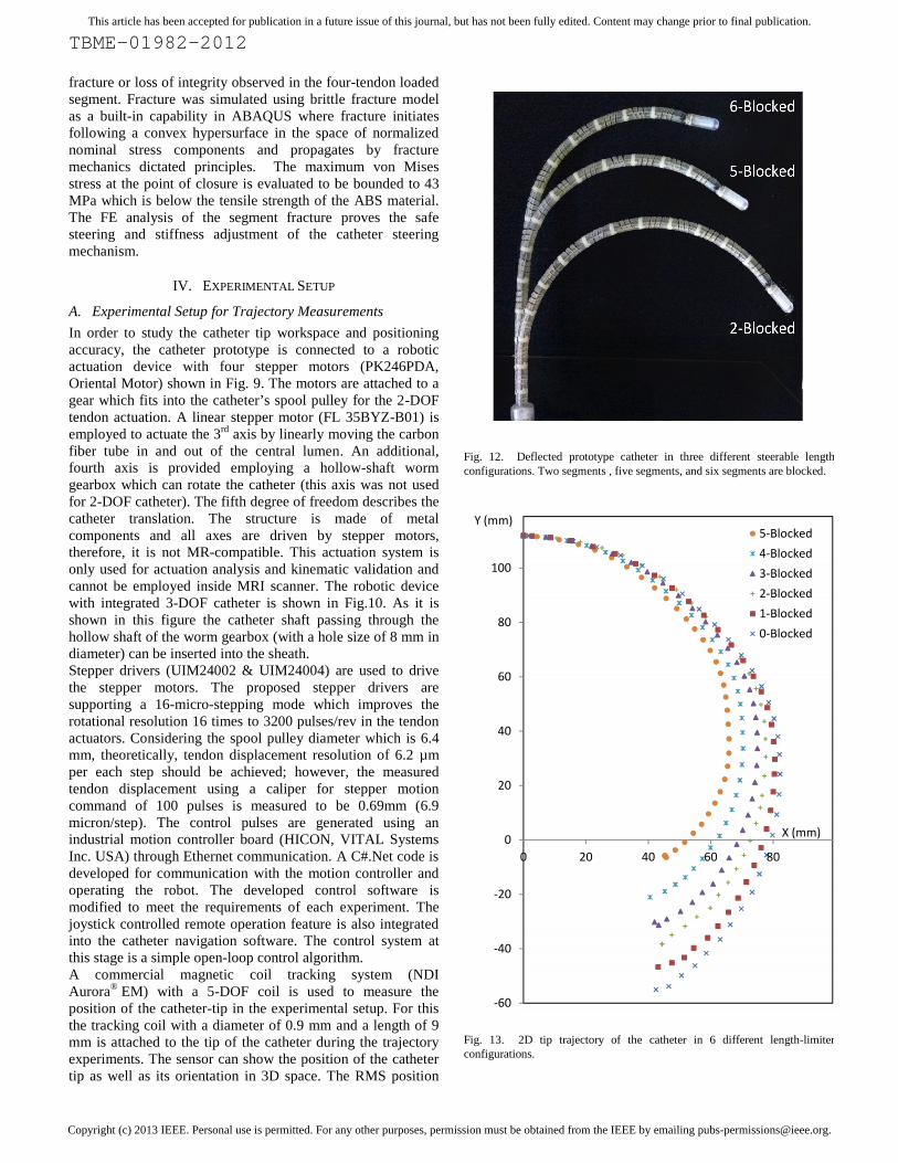
Fig. 12. Deflected prototype catheter in three different steerable lengthconfigurations. Two segments , five segments, and six segments are blocked.
Fig. 13. 2D tip trajectory of the catheter in 6 different length-limiterconfigurations.
TBME-01982-2012
fracture or loss of integrity observed in the four-tendon loadedsegment. Fracture was simulated using brittle fracture modelas a built-in capability in ABAQUS where fracture initiatesfollowing a convex hypersurface in the space of normalizednominal stress components and propagates by fracturemechanics dictated principles. The maximum von Misesstress at the point of closure is evaluated to be bounded to 43MPa which is below the tensile strength of the ABS material.The FE analysis of the segment fracture proves the safesteering and stiffness adjustment of the catheter steeringmechanism.
IV. EXPERIMENTAL SETUP
A. Experimental Setup for Trajectory Measurements
In order to study the catheter tip workspace and positioningaccuracy, the catheter prototype is connected to a roboticactuation device with four stepper motors (PK246PDA,Oriental Motor) shown in Fig. 9. The motors are attached to agear which fits into the catheter’s spool pulley for the 2-DOFtendon actuation. A linear stepper motor (FL 35BYZ-B01) isemployed to actuate the 3rd axis by linearly moving the carbonfiber tube in and out of the central lumen. An additional,fourth axis is provided employing a hollow-shaft wormgearbox which can rotate the catheter (this axis was not usedfor 2-DOF catheter). The fifth degree of freedom describes thecatheter translation. The structure is made of metalcomponents and all axes are driven by stepper motors,therefore, it is not MR-compatible. This actuation system isonly used for actuation analysis and kinematic validation andcannot be employed inside MRI scanner. The robotic devicewith integrated 3-DOF catheter is shown in Fig.10. As it isshown in this figure the catheter shaft passing through thehollow shaft of the worm gearbox (with a hole size of 8 mm indiameter) can be inserted into the sheath.Stepper drivers (UIM24002 & UIM24004) are used to drivethe stepper motors. The proposed stepper drivers aresupporting a 16-micro-stepping mode which improves therotational resolution 16 times to 3200 pulses/rev in the tendonactuators. Considering the spool pulley diameter which is 6.4mm, theoretically, tendon displacement resolution of 6.2 µmper each step should be achieved; however, the measuredtendon displacement using a caliper for stepper motioncommand of 100 pulses is measured to be 0.69mm (6.9micron/step). The control pulses are generated using anindustrial motion controller board (HICON, VITAL SystemsInc. USA) through Ethernet communication. A C#.Net code isdeveloped for communication with the motion controller andoperating the robot. The developed control software ismodified to meet the requirements of each experiment. Thejoystick controlled remote operation feature is also integratedinto the catheter navigation software. The control system atthis stage is a simple open-loop control algorithm.A commercial magnetic coil tracking system (NDIAurora® EM) with a 5-DOF coil is used to measure theposition of the catheter-tip in the experimental setup. For thisthe tracking coil with a diameter of 0.9 mm and a length of 9mm is attached to the tip of the catheter during the trajectoryexperiments. The sensor can show the position of the cathetertip as well as its orientation in 3D space. The RMS position
Fig. 12. Deflected prototype catheter in three different steerable lengthconfigurations. Two segments , five segments, and six segments are blocked.
Fig. 13. 2D tip trajectory of the catheter in 6 different length-limiterconfigurations.
-60
-40
-20
0
20
40
60
80
100
0 20 40
Y (mm)
TBME-01982-2012
fracture or loss of integrity observed in the four-tendon loadedsegment. Fracture was simulated using brittle fracture modelas a built-in capability in ABAQUS where fracture initiatesfollowing a convex hypersurface in the space of normalizednominal stress components and propagates by fracturemechanics dictated principles. The maximum von Misesstress at the point of closure is evaluated to be bounded to 43MPa which is below the tensile strength of the ABS material.The FE analysis of the segment fracture proves the safesteering and stiffness adjustment of the catheter steeringmechanism.
IV. EXPERIMENTAL SETUP
A. Experimental Setup for Trajectory Measurements
In order to study the catheter tip workspace and positioningaccuracy, the catheter prototype is connected to a roboticactuation device with four stepper motors (PK246PDA,Oriental Motor) shown in Fig. 9. The motors are attached to agear which fits into the catheter’s spool pulley for the 2-DOFtendon actuation. A linear stepper motor (FL 35BYZ-B01) isemployed to actuate the 3rd axis by linearly moving the carbonfiber tube in and out of the central lumen. An additional,fourth axis is provided employing a hollow-shaft wormgearbox which can rotate the catheter (this axis was not usedfor 2-DOF catheter). The fifth degree of freedom describes thecatheter translation. The structure is made of metalcomponents and all axes are driven by stepper motors,therefore, it is not MR-compatible. This actuation system isonly used for actuation analysis and kinematic validation andcannot be employed inside MRI scanner. The robotic devicewith integrated 3-DOF catheter is shown in Fig.10. As it isshown in this figure the catheter shaft passing through thehollow shaft of the worm gearbox (with a hole size of 8 mm indiameter) can be inserted into the sheath.Stepper drivers (UIM24002 & UIM24004) are used to drivethe stepper motors. The proposed stepper drivers aresupporting a 16-micro-stepping mode which improves therotational resolution 16 times to 3200 pulses/rev in the tendonactuators. Considering the spool pulley diameter which is 6.4mm, theoretically, tendon displacement resolution of 6.2 µmper each step should be achieved; however, the measuredtendon displacement using a caliper for stepper motioncommand of 100 pulses is measured to be 0.69mm (6.9micron/step). The control pulses are generated using anindustrial motion controller board (HICON, VITAL SystemsInc. USA) through Ethernet communication. A C#.Net code isdeveloped for communication with the motion controller andoperating the robot. The developed control software ismodified to meet the requirements of each experiment. Thejoystick controlled remote operation feature is also integratedinto the catheter navigation software. The control system atthis stage is a simple open-loop control algorithm.A commercial magnetic coil tracking system (NDIAurora® EM) with a 5-DOF coil is used to measure theposition of the catheter-tip in the experimental setup. For thisthe tracking coil with a diameter of 0.9 mm and a length of 9mm is attached to the tip of the catheter during the trajectoryexperiments. The sensor can show the position of the cathetertip as well as its orientation in 3D space. The RMS position
Fig. 12. Deflected prototype catheter in three different steerable lengthconfigurations. Two segments , five segments, and six segments are blocked.
Fig. 13. 2D tip trajectory of the catheter in 6 different length-limiterconfigurations.
60 80
5-Blocked4-Blocked3-Blocked2-Blocked1-Blocked0-Blocked
X (mm)

Copyright (c) 2013 IEEE. Personal use is permitted. For any other purposes, permission must be obtained from the IEEE by emailing [email protected].
This article has been accepted for publication in a future issue of this journal, but has not been fully edited. Content may change prior to final publication.
TBME-01982-2012
accuracy of the tracking system is claimed to be 0.70 mm for5-DOF tracking sensor by the manufacturer [20]. However,from a separate experiment conducted in our test environment,the measurement accuracy was found to be 0.9 mm. Theaccuracy of the RMS orientation measurement is evaluated tobe 0.28˚ (0.20˚ claimed by manufacturer [20]). The trackinginformation is recorded using our control software throughRS-232 communication with the Aurora magnetic trackingsystem. An average of 10 readings is acquired for eachrecorded position. Since the magnetic tracking system is verysensitive to electromagnetic distortions, the robotic actuator iskept away from the tracking field and the catheter steeringmechanism is fixed on a wooden table using a plastic fixtureoriented in parallel to the magnetic field. Fig.11 shows theexperimental tracking setup. The complete catheter with an 80cm MR-compatible catheter shaft is employed; hence, theachieved results are obtained based on the behavior of theentire prototype in a realistic scenario. The recorded positioninformation of the catheter-tip is used to study the 2D and 3Dcatheter-tip trajectories using one or two tendons. For a 2Dtrajectory measurement the catheter is positioned in aconfiguration in which its deflection occurs using the selectedsingle tendon in the XY plane parallel to the magnetic fieldgenerator front surface. Repeatability and hysteresis effect ofthe steering mechanism are evaluated.
B. Stiffness Adjustability Experimental Setup
An experimental setup using a commercial force sensor (ATINano 17) and a linear stage (KK40-2001, Hiwin) is employedapplying lateral forces to the catheter by moving the forcesensor against the catheter-tip and recording the force-displacement values. The catheter’s deflectable part is fixed tothe table and the applied force based on the force sensordisplacement is recorded. This setup was used to study theeffect of variation in deflectable length on lateral forcibility. Inaddition it is used to investigate the stiffness adjustabilityfeature of the presented prototype by increasing the tension inall the tendons simultaneously. This feature is believed toincrease the stiffness of the catheter where increasedforcibility is required.
C. Experimental MR-Compatibility Test Setup
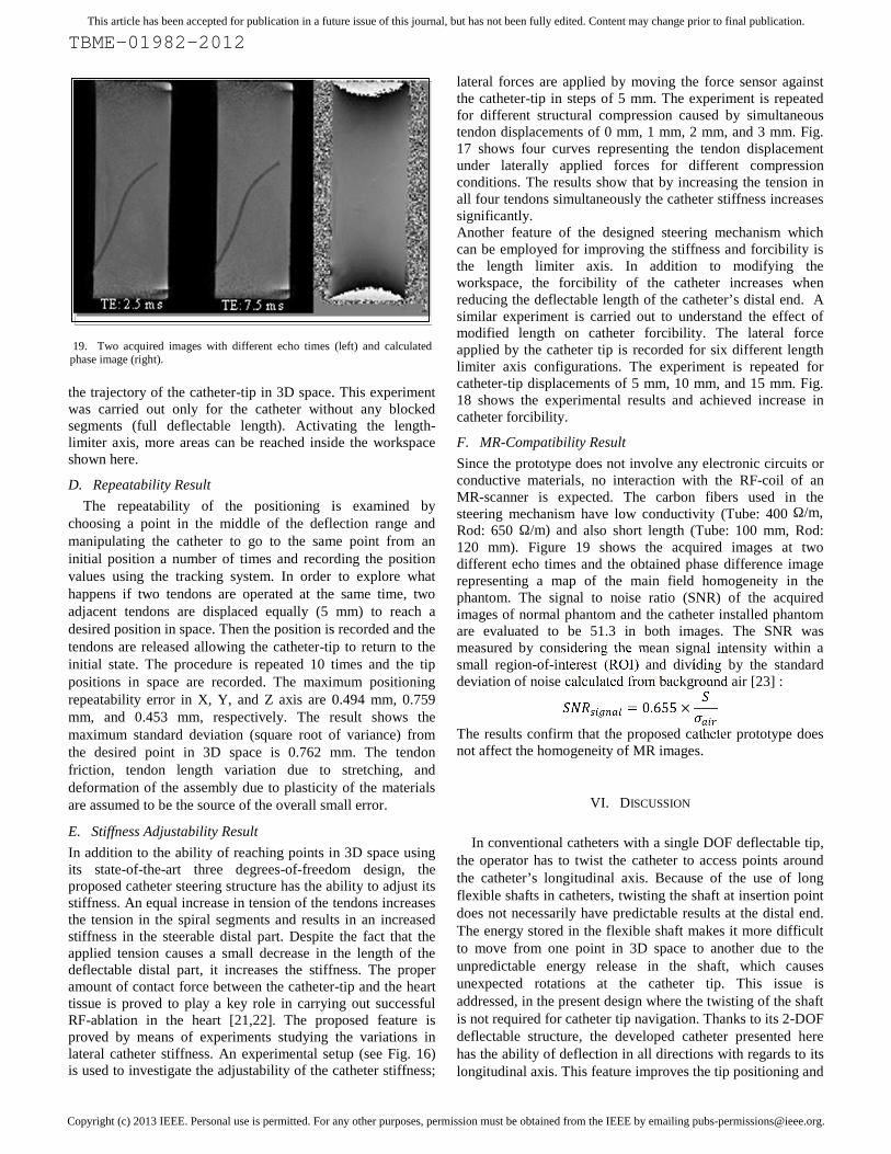
The proposed catheter prototype is tested on the potentialeffects on MR image quality [11]. A major issue is localdistortion of the main magnetic field homogeneity due tosusceptibility of the material and potential metalcontamination during the manufacturing process. For this awater-filled phantom with the catheter device (including thesteering mechanism, catheter shaft, and control knob) ismeasured inside a 1.5 Tesla scanner (Philips Achieva). Themain field homogeneity is estimated from a field map byacquiring two images at two different echo times (TE (echodelay time) =2.5/7.5 ms) and calculating phase difference ofboth images that contain real and imaginary components. Thephase difference at each pixel is proportional to the resonantfrequency at this location.
V. EXPERIMENTAL RESULTS
A. Planar Catheter-Tip Trajectory
Figure 12 shows the prototype catheter in three differentdeflectable length configurations. The in-plane trajectory ofthe catheter-tip using a single tendon is presented in Fig. 13.For this experiment the tendon has been actuated from the
Fig. 14. Hysteresis experiment results by full deflectable length catheter.
Fig. 15. A 3D tip trajectory experiment result demonstrates the workspace ofthe catheter-tip in full deflectable length where the length limiter axis is notemployed.
-40
-20
0
20
40
60
80
100
0 20 40 60 80
Forward
Reverse
Y (mm)
X (mm)
Copyright (c) 2013 IEEE. Personal use is permitted. For any other purposes, permission must be obtained from the IEEE by emailing [email protected].
This article has been accepted for publication in a future issue of this journal, but has not been fully edited. Content may change prior to final publication.
TBME-01982-2012
initial state up to 16 mm in steps of 0.4 mm displacements.The position data presented here is the average of 10 positionreadings which is received from the magnetic tracking devicefor each point after catheter was stable in each position. Theeffect of using a length-limiter axis (3rd DOF) in 6 differentdeflectable-length configurations is also shown in this figure.Starting with the full deflectable length of the steering part, theset of tip positions is shown as “0-Blocked” in Fig. 13. Thepresented curve shows the trajectory of the catheter-tipwithout any limitation in deflectable length. Then byadvancing the carbon fiber tube into the catheter lumen andlimiting the deflectable length by means of blocking the firsthelical segment the next set of points is recorded which isreferred as “1-Blocked” in this figure. Repeating theexperiment by blocking more and more segments all six setsof points are recorded and presented (Fig. 13). As a result ofusing the integrated length-limiter, the catheter can extend itsreach in the 3D space without the necessity of axialmovements. Besides, this additional axis provides extrasupport for the catheter when more force is required to beapplied when the tip is in contact with tissue.
B. Deflection Hysteresis Analysis
The trajectory of the catheter-tip during a forward and reversetendon displacement is recorded using the same experimentalsetup to measure potential hysteresis effects using a full lengthdeflection configuration. Similar to the trajectory experiment,the tendon is displaced up to 16 mm in steps of 0.4 mm andthen released along the same steps in reverse until it reachesagain the initial state; during this operation, the resultant tippositions are recorded. Fig.14 shows the catheter tip trajectoryduring the forward and reverse deflections. The experimentshows that the hysteresis effect prevents the catheter-tip torevisit its initial point when the tendon is released. This is theconsequence of the plastic properties of the deflectingcomponents when exposed to a large deflection.
C. Three-Dimensional Catheter-tip Trajectory
In traditional cardiac catheterization, catheter deflection canoccur in only one plane if a single or double tendon system(two tendons for bidirectional types) is employed. In such acase, the catheter twist is unavoidable for reaching pointsalong the catheter’s longitudinal axis. Because of theflexibility of the catheter shaft and friction, twisting thecatheter shaft at the insertion port depends on the energystored in the flexible shaft and does not necessarily result in apredictable and repeatable rotation of the tip. The ability of thepresented catheter to move the catheter tip in 3D is tested inthe same experimental setup as for the 2D case but using allindividual tendons and combinations of adjacent tendons. Theexperiment starts by actuating each of the four tendonsindividually in steps of 0.5 mm whilst recording the tipposition with a magnetic tracking coil system. Then allpossible combinations of driving adjacent tendons (in pairs oftwo) in parallel with variable step ratios covering the regionbetween the two tendons; the resultant tip positions arerecorded. In order to visualize the tip positions in 3Dcoordinates, the recorded cloud points are used to fit a meshrepresenting the reachable working space. Figure 15 shows
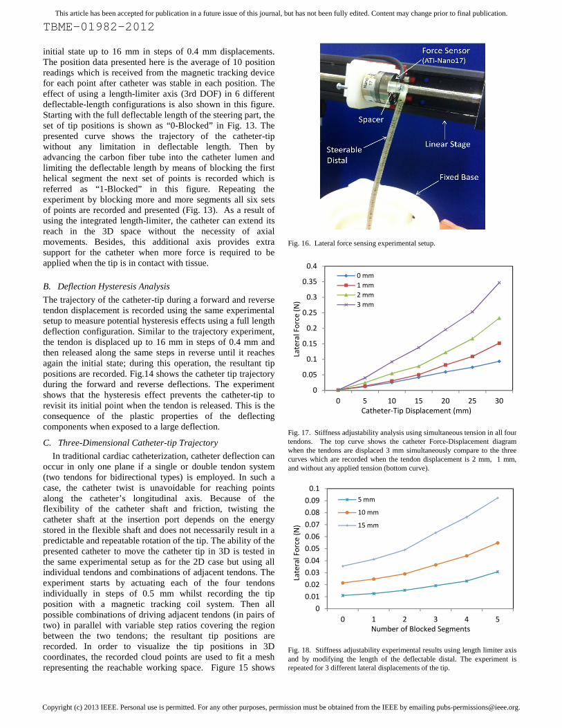
Fig. 16. Lateral force sensing experimental setup.
Fig. 17. Stiffness adjustability analysis using simultaneous tension in all fourtendons. The top curve shows the catheter Force-Displacement diagramwhen the tendons are displaced 3 mm simultaneously compare to the threecurves which are recorded when the tendon displacement is 2 mm, 1 mm,and without any applied tension (bottom curve).
Fig. 18. Stiffness adjustability experimental results using length limiter axisand by modifying the length of the deflectable distal. The experiment isrepeated for 3 different lateral displacements of the tip.
TBME-01982-2012
initial state up to 16 mm in steps of 0.4 mm displacements.The position data presented here is the average of 10 positionreadings which is received from the magnetic tracking devicefor each point after catheter was stable in each position. Theeffect of using a length-limiter axis (3rd DOF) in 6 differentdeflectable-length configurations is also shown in this figure.Starting with the full deflectable length of the steering part, theset of tip positions is shown as “0-Blocked” in Fig. 13. Thepresented curve shows the trajectory of the catheter-tipwithout any limitation in deflectable length. Then byadvancing the carbon fiber tube into the catheter lumen andlimiting the deflectable length by means of blocking the firsthelical segment the next set of points is recorded which isreferred as “1-Blocked” in this figure. Repeating theexperiment by blocking more and more segments all six setsof points are recorded and presented (Fig. 13). As a result ofusing the integrated length-limiter, the catheter can extend itsreach in the 3D space without the necessity of axialmovements. Besides, this additional axis provides extrasupport for the catheter when more force is required to beapplied when the tip is in contact with tissue.
B. Deflection Hysteresis Analysis
The trajectory of the catheter-tip during a forward and reversetendon displacement is recorded using the same experimentalsetup to measure potential hysteresis effects using a full lengthdeflection configuration. Similar to the trajectory experiment,the tendon is displaced up to 16 mm in steps of 0.4 mm andthen released along the same steps in reverse until it reachesagain the initial state; during this operation, the resultant tippositions are recorded. Fig.14 shows the catheter tip trajectoryduring the forward and reverse deflections. The experimentshows that the hysteresis effect prevents the catheter-tip torevisit its initial point when the tendon is released. This is theconsequence of the plastic properties of the deflectingcomponents when exposed to a large deflection.
C. Three-Dimensional Catheter-tip Trajectory
In traditional cardiac catheterization, catheter deflection canoccur in only one plane if a single or double tendon system(two tendons for bidirectional types) is employed. In such acase, the catheter twist is unavoidable for reaching pointsalong the catheter’s longitudinal axis. Because of theflexibility of the catheter shaft and friction, twisting thecatheter shaft at the insertion port depends on the energystored in the flexible shaft and does not necessarily result in apredictable and repeatable rotation of the tip. The ability of thepresented catheter to move the catheter tip in 3D is tested inthe same experimental setup as for the 2D case but using allindividual tendons and combinations of adjacent tendons. Theexperiment starts by actuating each of the four tendonsindividually in steps of 0.5 mm whilst recording the tipposition with a magnetic tracking coil system. Then allpossible combinations of driving adjacent tendons (in pairs oftwo) in parallel with variable step ratios covering the regionbetween the two tendons; the resultant tip positions arerecorded. In order to visualize the tip positions in 3Dcoordinates, the recorded cloud points are used to fit a meshrepresenting the reachable working space. Figure 15 shows
Fig. 16. Lateral force sensing experimental setup.
Fig. 17. Stiffness adjustability analysis using simultaneous tension in all fourtendons. The top curve shows the catheter Force-Displacement diagramwhen the tendons are displaced 3 mm simultaneously compare to the threecurves which are recorded when the tendon displacement is 2 mm, 1 mm,and without any applied tension (bottom curve).
Fig. 18. Stiffness adjustability experimental results using length limiter axisand by modifying the length of the deflectable distal. The experiment isrepeated for 3 different lateral displacements of the tip.
0
0.05
0.1
0.15
0.2
0.25
0.3
0.35
0.4
0 5 10 15
0 mm1 mm2 mm3 mm
Catheter-Tip Displacement (mm)
Late
ral F
orce
(N)
00.010.020.030.040.050.060.070.080.09
0.1
0 1 2
5 mm
10 mm
15 mm
Number of Blocked Segments
Late
ral F
orce
(N)
TBME-01982-2012
initial state up to 16 mm in steps of 0.4 mm displacements.The position data presented here is the average of 10 positionreadings which is received from the magnetic tracking devicefor each point after catheter was stable in each position. Theeffect of using a length-limiter axis (3rd DOF) in 6 differentdeflectable-length configurations is also shown in this figure.Starting with the full deflectable length of the steering part, theset of tip positions is shown as “0-Blocked” in Fig. 13. Thepresented curve shows the trajectory of the catheter-tipwithout any limitation in deflectable length. Then byadvancing the carbon fiber tube into the catheter lumen andlimiting the deflectable length by means of blocking the firsthelical segment the next set of points is recorded which isreferred as “1-Blocked” in this figure. Repeating theexperiment by blocking more and more segments all six setsof points are recorded and presented (Fig. 13). As a result ofusing the integrated length-limiter, the catheter can extend itsreach in the 3D space without the necessity of axialmovements. Besides, this additional axis provides extrasupport for the catheter when more force is required to beapplied when the tip is in contact with tissue.
B. Deflection Hysteresis Analysis
The trajectory of the catheter-tip during a forward and reversetendon displacement is recorded using the same experimentalsetup to measure potential hysteresis effects using a full lengthdeflection configuration. Similar to the trajectory experiment,the tendon is displaced up to 16 mm in steps of 0.4 mm andthen released along the same steps in reverse until it reachesagain the initial state; during this operation, the resultant tippositions are recorded. Fig.14 shows the catheter tip trajectoryduring the forward and reverse deflections. The experimentshows that the hysteresis effect prevents the catheter-tip torevisit its initial point when the tendon is released. This is theconsequence of the plastic properties of the deflectingcomponents when exposed to a large deflection.
C. Three-Dimensional Catheter-tip Trajectory
In traditional cardiac catheterization, catheter deflection canoccur in only one plane if a single or double tendon system(two tendons for bidirectional types) is employed. In such acase, the catheter twist is unavoidable for reaching pointsalong the catheter’s longitudinal axis. Because of theflexibility of the catheter shaft and friction, twisting thecatheter shaft at the insertion port depends on the energystored in the flexible shaft and does not necessarily result in apredictable and repeatable rotation of the tip. The ability of thepresented catheter to move the catheter tip in 3D is tested inthe same experimental setup as for the 2D case but using allindividual tendons and combinations of adjacent tendons. Theexperiment starts by actuating each of the four tendonsindividually in steps of 0.5 mm whilst recording the tipposition with a magnetic tracking coil system. Then allpossible combinations of driving adjacent tendons (in pairs oftwo) in parallel with variable step ratios covering the regionbetween the two tendons; the resultant tip positions arerecorded. In order to visualize the tip positions in 3Dcoordinates, the recorded cloud points are used to fit a meshrepresenting the reachable working space. Figure 15 shows
Fig. 16. Lateral force sensing experimental setup.
Fig. 17. Stiffness adjustability analysis using simultaneous tension in all fourtendons. The top curve shows the catheter Force-Displacement diagramwhen the tendons are displaced 3 mm simultaneously compare to the threecurves which are recorded when the tendon displacement is 2 mm, 1 mm,and without any applied tension (bottom curve).
Fig. 18. Stiffness adjustability experimental results using length limiter axisand by modifying the length of the deflectable distal. The experiment isrepeated for 3 different lateral displacements of the tip.
15 20 25 30Catheter-Tip Displacement (mm)
3 4 5Number of Blocked Segments
Copyright (c) 2013 IEEE. Personal use is permitted. For any other purposes, permission must be obtained from the IEEE by emailing [email protected].
This article has been accepted for publication in a future issue of this journal, but has not been fully edited. Content may change prior to final publication.
TBME-01982-2012
the trajectory of the catheter-tip in 3D space. This experimentwas carried out only for the catheter without any blockedsegments (full deflectable length). Activating the length-limiter axis, more areas can be reached inside the workspaceshown here.
D. Repeatability Result
The repeatability of the positioning is examined bychoosing a point in the middle of the deflection range andmanipulating the catheter to go to the same point from aninitial position a number of times and recording the positionvalues using the tracking system. In order to explore whathappens if two tendons are operated at the same time, twoadjacent tendons are displaced equally (5 mm) to reach adesired position in space. Then the position is recorded and thetendons are released allowing the catheter-tip to return to theinitial state. The procedure is repeated 10 times and the tippositions in space are recorded. The maximum positioningrepeatability error in X, Y, and Z axis are 0.494 mm, 0.759mm, and 0.453 mm, respectively. The result shows themaximum standard deviation (square root of variance) fromthe desired point in 3D space is 0.762 mm. The tendonfriction, tendon length variation due to stretching, anddeformation of the assembly due to plasticity of the materialsare assumed to be the source of the overall small error.
E. Stiffness Adjustability Result
In addition to the ability of reaching points in 3D space usingits state-of-the-art three degrees-of-freedom design, theproposed catheter steering structure has the ability to adjust itsstiffness. An equal increase in tension of the tendons increasesthe tension in the spiral segments and results in an increasedstiffness in the steerable distal part. Despite the fact that theapplied tension causes a small decrease in the length of thedeflectable distal part, it increases the stiffness. The properamount of contact force between the catheter-tip and the hearttissue is proved to play a key role in carrying out successfulRF-ablation in the heart [21,22]. The proposed feature isproved by means of experiments studying the variations inlateral catheter stiffness. An experimental setup (see Fig. 16)is used to investigate the adjustability of the catheter stiffness;
lateral forces are applied by moving the force sensor againstthe catheter-tip in steps of 5 mm. The experiment is repeatedfor different structural compression caused by simultaneoustendon displacements of 0 mm, 1 mm, 2 mm, and 3 mm. Fig.17 shows four curves representing the tendon displacementunder laterally applied forces for different compressionconditions. The results show that by increasing the tension inall four tendons simultaneously the catheter stiffness increasessignificantly.Another feature of the designed steering mechanism whichcan be employed for improving the stiffness and forcibility isthe length limiter axis. In addition to modifying theworkspace, the forcibility of the catheter increases whenreducing the deflectable length of the catheter’s distal end. Asimilar experiment is carried out to understand the effect ofmodified length on catheter forcibility. The lateral forceapplied by the catheter tip is recorded for six different lengthlimiter axis configurations. The experiment is repeated forcatheter-tip displacements of 5 mm, 10 mm, and 15 mm. Fig.18 shows the experimental results and achieved increase incatheter forcibility.
F. MR-Compatibility Result
Since the prototype does not involve any electronic circuits orconductive materials, no interaction with the RF-coil of anMR-scanner is expected. The carbon fibers used in thesteering mechanism have low conductivity (Tube: 400 Ω/m,Rod: 650 Ω/m) and also short length (Tube: 100 mm, Rod:120 mm). Figure 19 shows the acquired images at twodifferent echo times and the obtained phase difference imagerepresenting a map of the main field homogeneity in thephantom. The signal to noise ratio (SNR) of the acquiredimages of normal phantom and the catheter installed phantomare evaluated to be 51.3 in both images. The SNR wasmeasured by considering the mean signal intensity within asmall region-of-interest (ROI) and dividing by the standarddeviation of noise calculated from background air [23] := 0.655 ×The results confirm that the proposed catheter prototype doesnot affect the homogeneity of MR images.
VI. DISCUSSION
In conventional catheters with a single DOF deflectable tip,the operator has to twist the catheter to access points aroundthe catheter’s longitudinal axis. Because of the use of longflexible shafts in catheters, twisting the shaft at insertion pointdoes not necessarily have predictable results at the distal end.The energy stored in the flexible shaft makes it more difficultto move from one point in 3D space to another due to theunpredictable energy release in the shaft, which causesunexpected rotations at the catheter tip. This issue isaddressed, in the present design where the twisting of the shaftis not required for catheter tip navigation. Thanks to its 2-DOFdeflectable structure, the developed catheter presented herehas the ability of deflection in all directions with regards to itslongitudinal axis. This feature improves the tip positioning and
19. Two acquired images with different echo times (left) and calculatedphase image (right).
Copyright (c) 2013 IEEE. Personal use is permitted. For any other purposes, permission must be obtained from the IEEE by emailing [email protected].
This article has been accepted for publication in a future issue of this journal, but has not been fully edited. Content may change prior to final publication.
TBME-01982-2012
navigation by improving the maneuverability of the steerablemechanism. The hysteresis diagram indicates that in order toreturn the catheter back to the initial position after a largedeflection the opposite tendon needs to be actuated. This isdue to the large deflection. Therefore having two degrees offreedom provides the ability to deflect in opposite direction toovercome positioning error caused by hysteresis effect. Atpresent, in order to modify the curvature or length of thedeflectable part of the catheter, an external sheath is employedin commercial catheters. The additional sheath must be largerin diameter than the used catheter enveloping the catheteritself. However, in the presented catheter steering design acarbon fiber tube is used to modify the length of thedeflectable part as a result of reducing the number of segmentsin action, yet the catheter outer diameter is not increased. Thisadditional degree of freedom extends the workspace of thecatheter and increases the forcibility.
In an EP ablation procedure, the adequate contact forcebetween the catheter-tip and soft tissue is known to be animportant factor for successful ablation [21,22]. In contrast toconventional catheters, the spiral structure of the catheterpresented here is stiffness adjustable. Therefore, the operatorcan decide to increase the stiffness of the catheter where it isrequired by simply increasing the tension in all tendonssimultaneously. MR-compatibility is achieved as a result ofusing MR-safe materials in the steering structure. The highpositioning accuracy and the improved navigation efficiencyare the most significant advantages of the proposed steeringmechanism presented in this paper. Since in the present designthe catheter lumen is filled with the carbon fiber rod and tube,the flexible sleeve which is located inside the central lumen ofthe catheter has to be replaced in future with a preciselyextruded tubing to provide lumens for injection and otherapplications.
VII. CONCLUSIONS
A novel 3-DOF MR-compatible segment based steeringmechanism for cardiac catheters has been created employing ahigh-resolution rapid prototyping technique. The proposedcatheter steering mechanism can deflect in all directions awayfrom its longitudinal axis thanks to its 2-DOF tendon drivensegment structure. The deflectable length of the catheter canbe adjusted using an insertable carbon fiber tube addinganother degree of freedom to the steering mechanism yet notaffecting the outer diameter of the device. Experimentalresults indicate that the catheter tip can be precisely navigatedin 3D space employing four tendons without the need to twistthe catheter shaft. In addition, the developed steerablemechanism is benefitting from being stiffness adjustable. TheMR-compatible materials used in the steering mechanism ofthe catheter distal make it safe to be used for robot-basedcatheterization inside an MRI scanner. The proposed cathetersteering mechanism represents the foundation to conductentire cardiac catheterization procedures inside an MRIscanner using an autonomous MR-compatible robotic systemcontrolled using MR imaging feedback. The MR-compatible
robotic catheter actuation device is currently underdevelopment in our research group. This robot is based onhydraulic actuation in a master-slave hydraulic system. Thepreliminary result is promising but further improvement inpositioning accuracy and actuation speed is necessary. Forcatheter-tip trajectory evaluation a magnetic tracking coil isused in this research, this is also planned to be replaced withan active MR tracking coil in future work where the catheter isto be used inside MRI scanner.
ACKNOWLEDGMENT
The authors thank Ms. Hanne Guthormsen and Mr. JimTrotter for their invaluable assistance in designing the roboticactuator and conducting the experiments.
REFERENCES
[1] J. Peirs, J. Clijnen, D. Reynaerts et al., “A micro optical force sensor forforce feedback during minimally invasive robotic surgery,” Sensors andActuators A: Physical, vol. 115, no. 2-3, pp. 447-455, 2004.
[2] P. Polygerinos, A. Ataollahi, T. Schaeffter et al., “MRI-CompatibleIntensity-Modulated Force Sensor for Cardiac CatheterizationProcedures,” Biomedical Engineering, IEEE Transactions on, vol. 58,no. 3, pp. 721-726, 2011.
[3] C. Yi, et al., "Multi-turn, tension-stiffening catheter navigation system,"in Robotics and Automation (ICRA), 2010 IEEE InternationalConference on, 2010, pp. 5570-5575.
[4] J. Driller, "Kinetics of magnetically guided catheters," Magnetics, IEEETransactions on, vol. 6, pp. 467-471, 1970.
[5] P. Dupont, J. Lock, B. Itkowitz, and E. Butler, “Design and control ofconcentric-tube robots,” Robotics, IEEE Transactions on, vol. 26, pp.209 –225, april 2010.
[6] M. A. Martinelly and W.C. Haase, ”Method and system for navigating acatheter probe,” U.S. RE40,852, July 14, 2009.
[7] Sheldon D. Gould and Garry T. Riggs, “Curving Tip Catheter,” U.S.Patent 4,586,923, May 6, 1986.
[8] M. Eng, R. R.Viswanathan, P. R. Werp, I. Tunay, A. K. Pandey, and G.T. Munger, “Electrophysiology Catheter,” U.S. Patent 6,980,843, Dec.27, 2005.
[9] P. Kanagaratnam, et al., "Experience of robotic catheter ablation inhumans using a novel remotely steerable catheter sheath," Journal ofInterventional Cardiac Electrophysiology, vol. 21, pp. 19-26, 2008.
[10] R. Razavi, et al., "Cardiac catheterisation guided by MRI in children andadults with congenital heart disease," The Lancet, vol. 362, pp. 1877-1882, 2003.
[11] T. Schaeffter and H. Dahnke, "Magnetic Resonance Imaging andSpectroscopy," in Molecular Imaging I. vol. 185/1, W. Semmler and M.Schwaiger, Eds., ed: Springer Berlin Heidelberg, 2008, pp. 75-90.
[12] J. E. Mackewn, et al., "Performance Evaluation of an MRI-CompatiblePre-Clinical PET System Using Long Optical Fibers," Nuclear Science,IEEE Transactions on, vol. 57, pp. 1052-1062, 2010.
[13] RJ. Lederman, “Cardiovascular interventional magnetic resonanceimaging,” in Circulation, 2005, PP-3009-17.
[14] A. Tzifa, T. Schaeffter, R. Razavi, “MR imaging-guided cardiovascularinterventions in young children,” in Magn Reson Imaging Clin N Am,2012, PP-117-28.
[15] SR. Dukkipati, et al., “Electroanatomic mapping of the left ventricle in aporcine model of chronic myocardial infarction with magneticresonance-based catheter tracking,” in Circulation, 2008, vol.118, PP-853–862.
[16] M. Bock, FK. Wacker, “MR-guided intravascular interventions:techniques and applications,” in J Magn Reson Imaging, 2008, PP-326-38.
[17] MK. Konings, LW. Bartels, HFM. Smits, CJG. Bakker, “Heating aroundintravascular guidewires by resonating RF waves,” in J Magn ResonImaging, 2000, PP-79–85.
[18] S. Weiss, et al. “In vivo evaluation and proof of radiofrequency safety ofa novel diagnostic MR-electrophysiology catheter,” in MagneticResonance in Medicine, 2011, PP-770–777.
Copyright (c) 2013 IEEE. Personal use is permitted. For any other purposes, permission must be obtained from the IEEE by emailing [email protected].
This article has been accepted for publication in a future issue of this journal, but has not been fully edited. Content may change prior to final publication.
TBME-01982-2012
[19] “Artisan ExtendTM Commercial Catheter Developed by Hansen Medical”Internet: http://www.hansenmedical.com/us/products/ep/artisan-control-catheter.php
[20] “AURORA EM Tracking System Specification Brochure.” Internet :http://www.ndigital.com/medical/documents/aurora/aurora-brochure.pdf
[21] VY. Reddy, et al., “ The relationship between contact force and clinicaloutcome during radiofrequency catheter ablation of atrial fibrillation inthe TOCCATA study,” in Heart Rhthm, Nov.9(11), 2012, PP-1789-1795.
[22] A. Thiagalingam, et al., “ Importance of Catheter Contact Force DuringIrrigated Radiofrequency Ablation: Evaluation in a Porcine ExVivo Model Using a Force-Sensing Catheter,” in Journal ofCardiovascular Electrophysiology, 2010, Vol. 21, PP-806-811.
[23] L. Kaufman, et al., “ Measuring signal-to- noise ratios in MR imaging,”in Radiology, 173, 1989, PP-265-267.
Asghar Ataollahi received the B.Sc. degree inelectrical engineering and control systems fromK. N. Toosi University of Technology, Tehran,Iran, and the M.Sc. in mechanical engineeringresearch from the King’s College London,London, U.K., where he is currently workingtoward the Ph.D. degree. He specializes inmedical robotics as a member of Centre forRobotics Research (CORE) and collaborateswith cardiologists and urologists at St.Thomas’Hospital and Guy’s Hospital, London.
Rashed Karim received his B.Sc degree inComputer sciences from the University ofToronto in 2002 and his M.Sc degree inadvanced computing in 2005. From 2005 to2009, he was with the Department of Computing,Imperial College London, where he was involvedin developing image processing algorithms withapplications in cardiac MRI images. He wasawarded a Doctor of Philosophy degree in leftatrium segmentation from cardiac MR images.Since 2010, he has been working as aPostdoctoral Research Fellow investigating
several problems in cardiac image processing. In particular, problems arisingin image segmentation, 3D visualization and image guidance.
Arash S. Fallah is a Research Associate instructural engineering at Imperial College Londonspecialising in computational and analyticalmodelling of blast and impact loaded monolithic,composite and hybrid structures and systems. Hisinterests include frequency filtering in phononicmetamaterials and lattices, extended finiteelement formulation of plated structures,nonlinear dynamics and chaos, damage andfracture in composites and constitutive visco-elastic, plastic and visco-plastic formulations formetals and composites. Much of his work is
funded by EPSRC, Dstl/MoD, Health and Safety Executive and the Office ofNaval Research Global and is conducted in collaboration with University ofCape Town and US Naval Academy.
Kawal Rhode received his B.Sc. degree inBasic Medical Sciences and RadiologicalSciences from King's College London in 1992.From 1998 to 2001, he was with the Departmentof Surgery, University College London, wherehe was engaged in investigating quantitativeblood flow analysis using X-ray angiography aspart of his Doctor of Philosophy degree. From2001 to 2007, he was a Postdoctoral ResearchFellow in the Division of Imaging Sciences andBiomedical Engineering, King's College
London, where he was involved in image-guided interventions, particularlycatheter-based electrophysiology procedures, and has been an Assistant
Professor in the Division since 2007 and subsequently an Associate Professorsince 2011. He has authored or coauthoredmore than 125 publications in journals, conference proceedings, andbook chapters, and holds several patents. His research interestsinclude image-guided cardiovascular interventions, cardiacelectromechanical modeling, computer simulation of minimallyinvasive procedures and medical robotics.
Lakmal D. Seneviratne (M’05) received theB.Sc.(Eng.) and Ph.D. degrees in mechanicalengineering from the King’s College London,London, U.K. He is currently a Professor ofrobotics at Khalifa University, Abu Dhabi, UAE,on secondment from King’s College London,where he is a Professor of mechatronics. Hiscurrent research interests include robotics andautonomous systems. He has authored orcoauthored more than 250 refereed researchpapers related to robotics and mechatronics.Prof. Seneviratne is a Fellow of both the
Institution of Engineering and Technology (IET) and the IMechE.
Reza Razavi received the M.D. degree on MRGuided Cardiac catheterization from the King’sCollege London, London, U.K. He studiedmedicine at St. Bartholomew’s Hospital MedicalSchool, University of London, London. Hetrained in Paediatrics and Paediatric Cardiology atGuy’s and St. Thomas’ Hospital London. He wasa Clinical Research Fellow. He was appointedas a Lecturer and a Honorary Consultant inPaediatric Cardiology in August 2001, and aProfessor of Paediatric Cardiovascular Science inOctober 2004. He has been the Deputy Head of
the Division of Imaging Sciences since January 2005 and the Head ofDivision since January 2007. He is the Director of the KCL Centre forExcellence in Medical Engineering funded by the Welcome Trust andEngineering and Physical Sciences Research Council. His current researchinterests include cardiovascular MRI- and MR-guided cardiac catheterization.
Tobias Schaeffter studied electrical engineeringin Berlin and received the Ph.D. degree inmagnetic resonance imaging (MRI) from theUniversity of Bremen (Prof. Leibfritz), Bremen,Germany. From 1996 to 2006, he was a PrincipalScientists at the Philips Research Laboratories,Hamburg, Germany. In April 2006, he took upthe post as the Philip Harris Professor of imagingsciences at the King’s College London, London,U.K. His current research interests include theinvestigation of new acquisition andreconstruction techniques for cardiovascularand quantitative MRI. In particular he works on
new techniques for MR-guided electrophysiology procedures, and thequantitative assessment of ablation procedures.interests in minimally invasivesurgery and robotics. He has also pioneered a technique for Botulinum toxininjection for the treatment of overactive bladders.
Kaspar Althoefer received the Dipl.-Ing. degreein electronic engineering from the University ofAachen, Aachen, Germany, and the Ph.D. degreein electronic engineering from King’s CollegeLondon, London, U.K. He is currently aProfessor of Robotics and Intelligent Systems andHead of the Center for Robotics Research(CoRe), Department of Informatics, King’sCollege London. He has been involved inresearch on mechatronics since 1992 and gainedconsiderable expertise in the areas of sensing,sensor signal analysis, embedded intelligence,
and sensor data interpretation using neural networks and fuzzy logic, as wellas robot-based applications He has authored or coauthored more than 180refereed research papers related to mechatronics and robotics.