Embed Size (px)
Citation preview
3 in 1 COMBINED
PURE SINE WAVE INVERTER UPS / BATTERY CHARGER
(SOLAR & SHORE) USER MANUAL
利佳興業股份有限公司 RICH ELECTRIC CO.,LTD.
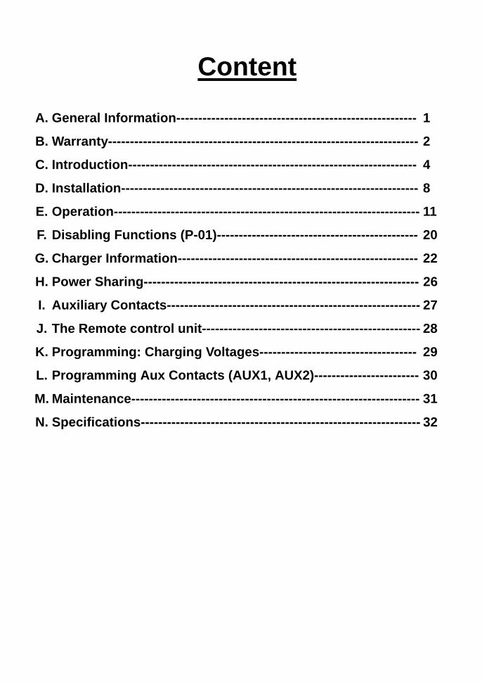
Content
A. General Information------------------------------------------------------- 1
B. Warranty----------------------------------------------------------------------- 2
C. Introduction------------------------------------------------------------------ 4
D. Installation-------------------------------------------------------------------- 8
E. Operation---------------------------------------------------------------------- 11
F. Disabling Functions (P-01)---------------------------------------------- 20
G. Charger Information------------------------------------------------------- 22
H. Power Sharing--------------------------------------------------------------- 26
I. Auxiliary Contacts---------------------------------------------------------- 27
J. The Remote control unit-------------------------------------------------- 28
K. Programming: Charging Voltages------------------------------------ 29
L. Programming Aux Contacts (AUX1, AUX2)------------------------ 30
M. Maintenance------------------------------------------------------------------ 31
N. Specifications---------------------------------------------------------------- 32
General: “ 3 in 1” It is a powerful pure sine wave inverter, a sophisticated battery
charger that features adaptive charge technology and a high-speed AC transfer switch in a single compact enclosure.
Besides all this functions ,however, the “3 in 1” has several advanced features that provides a range of new applications as outlined bellow: In the event of a grid failure ,or shore or generator power being disconnected, the inverter within the “3 in 1” is automatically In less than 20 milliseconds activated and takes over supply to the connected loads.
Allowed them to continue to operate without disruption. The “3 in 1” is very powerful battery charger. It will therefore draw a lot of current from the generator or shore side supply.
INVERTER: Pure Sine Wave AC output. Very low total harmonic distortion (< 2 % ) High surge capacity and soft-start design for heavy inductive loads such as air
conditioning Load detection system for “power saving” mode Extremely high efficiency.
Battery Charger : The “3 in 1” series is built around a bi-directional converter , that operates as
an inverter or as a battery charger high capacity three-stage Battery charger Equalization mode conditions Battery for longer life
Multistage charger-power factor corrected for superior Charging temperature sensitive charging for optional Care of all batteries ( temperature sensor optional ) Built in solar charge
regulator. Bypass Function: Automatic 60 A (3000W ) / 30 A ( 1500W ) transfer relay turns inverter and
charger on / off. Fast ( UPS ) mode or delay mode of the Bypass switch.
Power sharing prevent tripping of shore power breaker. Basic Remote Control: Power output on / off Function mode select Programming Battery charging voltage Error message display Programming auxiliary relay (x2 ) Programming input current limit for power share
A. General Information
Operating instructions This manual is a part of the delivery package of every Invertek inverter-charger. It
serves as Guidelines for safe and efficient operation of Invertek. The instructions are only valid for use with the following models and accessories. Invertek DAI-1500C-12xx / DAI-3000C-12xx Invertek DAI-1500C-24xx / DAI-1500C-24xx Temperature BTS-A-15 (m) Remote controller RCC-A-03 (3m) / RCC-A-15 (15m)
Any personnel who install a Invertek and / or works with it must be fully familiar with the contents of this manual and must follow exactly all the warnings and safety instructions. A qualified and trained personnel must carry out installation of , or any work on the Invertek . Installation and application must comply with the respective local installations codes and safety regulations.
-1-
B. Warranty During production and assembling, all Invertek Inverter / Chargers go through many testing procedures. Every invertek has its own serial number, which helps to refer back to its original data in the event of controls or repairs. That is why you should never remove the identification plate showing the serial number and must ensure you return your warranty card as soon as possible. The warranty period for your Invertek is 1 Year. Rich Electric Warranty Terms and Conditions Rich Electric warrants this product against defects in material or workmanship, to the original purchaser only for an initial period of 60 days from date of purchase, when in normal use and service. The warranty period will be extended to a total of one (1) year if a completed warranty card is received within 60 days of purchase. No warranty will be provided on units which have not been paid for in full. Some models may have the option of purchasing an extended warranty period, see elsewhere in this manual for details. This manufacturers warranty is in addition to your consumer rights under local trade practices act. This warranty does not extend to products which have been opened, altered or repaired by persons other than authorized by Rich Electric or to products which become defective due to acts of God, fire, sabotage, vandalism, contaminated fluids, negligence or failure to operate, house and maintain the product in accordance with instructions provided in this manual. It is extremely important that all installation instructions contained within this manual are strictly adhered to , failure to do so will void your warranty. Except for the foregoing expressed warranty Rich Electric makes no warranty, expressed or implied, including but not limited to, the warranty of merchantability or fitness for a particular purpose. Rich Electric will repair or replace the defective product in accordance with its best judgment, For service under warranty, the buyer or installer must contact Rich Electric to obtain a “Return Materials Advice” (RMA) document and shipping instructions before returning the product to the factory including , installers time. Rich Electric will pay return freight charges, if the product is found to be defective, within the terms of the warranty. Repair or replacement of any unit does not extend the original warranty terms in any way. This warranty does not cover repairs made necessary due to the product coming in contact with dirt, abrasives, moisture, rust, corrosion, varnish or other similar, or failure due to poor quality or poor condition batteries.
-2-
Rich Electric reserve the right with some models to supply an accredited installer with replacement parts, this may allow the unit to become operable much quicker. In this case Rich Electric are not responsible for any costs of the installer’s time or traveling expenses. Replacement parts are sent at Rich Electric discretion. Rich Electric will in no way be held responsible for any losses incurred due to the malfunctioning or failure of a product. Suitably qualified personnel must carry out wiring, failure to do so will void warranty. If you have any questions about this warranty please do not hesitate to contact us. Caution: Even when a Invertek has been completely disconnected, there can Still be deadly voltages present at the OUTPUT. To remove these voltages you must switch the Invertek ON with the ON/OFF switch. After one minute the electronics are discharged and any work can now be safely carried out. Caution: In normal use lead-acid and lead-gel batteries give out explosive gases. Never smoke or allow a spark or flame in the vicinity of batteries. The batteries must always be stored or placed in a well ventilated area, they should be placed in such a way that there is no danger of short circuiting through carelessness. Never charge frozen batteries. The Invertek is not to be used or sold for life support equipment or applications. B.1 Special Precautions While working on batteries there should always be a second person close to you or within your voice range, in case help is needed. Plenty of fresh water and soap must be ready at hand so that in case of acid coming in contact with skin, eyes and clothes, the areas in question can be thoroughly washed. If acid enters the eyes, you must thoroughly wash the eyes with cold running water for at least 15 minutes. It is recommended that you immediately consult a medical doctor. Baking powder neutralizes battery acid electrolyte. Always keep some at hand. Special care must be taken when working with metal tools near or on the batteries. With tools such as screwdrivers, spanners etc. short-circuits can result. Sparks produced by the short-circuit can cause an explosion. When working on batteries all personal metal items such as rings, necklaces and bracelets must be removed. Batteries are so powerful that short-circuit with these items can melt them and thus cause severe burns. Always follow the battery manufacturers instructions. Under certain conditions your Invertek or a connected generator can start automatically. While working on an electrical installation you must ensure that these appliances are disconnected before commencing any work.
-3-
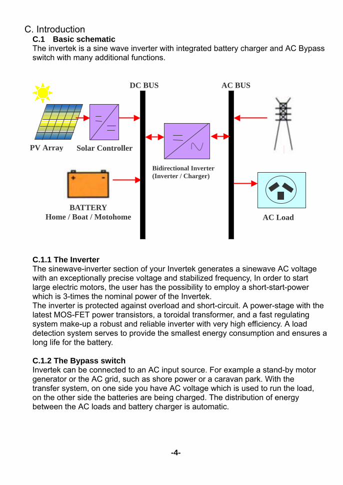
C. Introduction C.1 Basic schematic The invertek is a sine wave inverter with integrated battery charger and AC Bypass switch with many additional functions. C.1.1 The Inverter The sinewave-inverter section of your Invertek generates a sinewave AC voltage with an exceptionally precise voltage and stabilized frequency, In order to start large electric motors, the user has the possibility to employ a short-start-power which is 3-times the nominal power of the Invertek. The inverter is protected against overload and short-circuit. A power-stage with the latest MOS-FET power transistors, a toroidal transformer, and a fast regulating system make-up a robust and reliable inverter with very high efficiency. A load detection system serves to provide the smallest energy consumption and ensures a long life for the battery. C.1.2 The Bypass switch Invertek can be connected to an AC input source. For example a stand-by motor generator or the AC grid, such as shore power or a caravan park. With the transfer system, on one side you have AC voltage which is used to run the load, on the other side the batteries are being charged. The distribution of energy between the AC loads and battery charger is automatic.
-4-
PV Array Solar Controller
BATTERY Home / Boat / Motohome
DC BUS
Bidirectional Inverter (Inverter / Charger)
AC BUS
AC Load
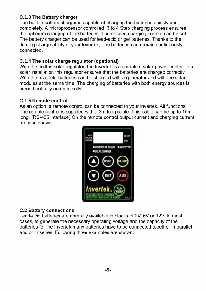
C.1.3 The Battery charger The built-in battery charger is capable of charging the batteries quickly and completely. A microprocessor controlled, 3 to 4 Step charging process ensures the optimum charging of the batteries. The desired charging current can be set. The battery charger can be used for lead-acid or gel batteries. Thanks to the floating charge ability of your Invertek, The batteries can remain continuously connected. C.1.4 The solar charge regulator (opetional) With the built-in solar regulator, the Invertek is a complete solar-power-center. In a solar installation this regulator ensures that the batteries are charged correctly. With the Invertek, batteries can be charged with a generator and with the solar modules at the same time. The charging of batteries with both energy sources is carried out fully automatically. C.1.5 Remote control As an option, a remote control can be connected to your Invertek, All functions The remote control is supplied with a 3m long cable. This cable can be up to 15m long. (RS-485 interface) On the remote control output current and charging current are also shown.
C.2 Battery connections Lead-acid batteries are normally available in blocks of 2V, 6V or 12V. In most cases, to generate the necessary operating voltage and the capacity of the batteries for the Invertek many batteries have to be connected together in parallel and or in series. Following three examples are shown:
-5-
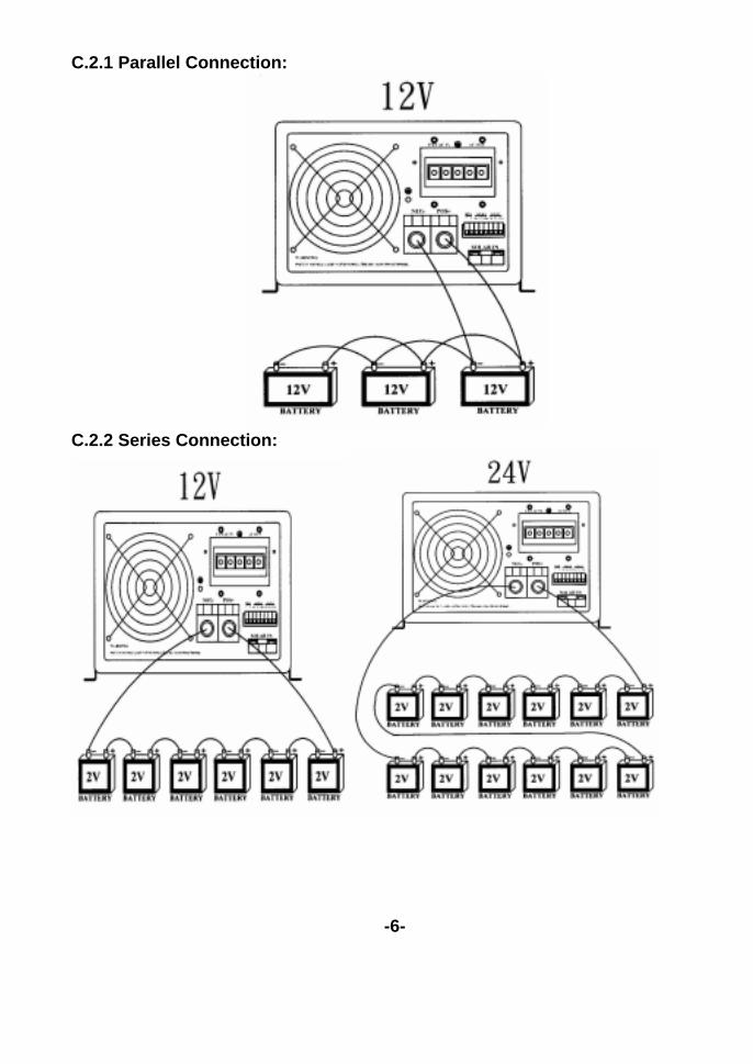
C.2.1 Parallel Connection:
C.2.2 Series Connection:
-6-
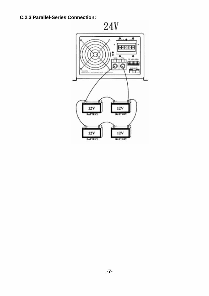
C.2.3 Parallel-Series Connection:
-7-
D. Installation D.1 Location The location of the Invertek must be chosen by the following criteria: Protection from unauthorized handling. Dry dust free room, no condensation, no rodents. Never install directly over the battery and never in a cabinet together
with the batteries. Keep ventilation holes free. The ventilation of the Invertek is designed in such a
way that it will work most efficiently when mounted vertically. In mobile installation it is important to keep vibrations to a minimum.
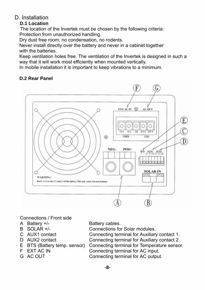
D.2 Rear Panel
Connections / Front side A Battery +/- Battery cables. B SOLAR +/- Connections for Solar modules. C AUX1 contact Connecting terminal for Auxiliary contact 1. D AUX2 contact Connecting terminal for Auxiliary contact 2. E BTS (Battery temp. sensor) Connecting terminal for Temperature sensor. F EXT AC IN Connecting terminal for AC input. G AC OUT Connecting terminal for AC output.
-8-
D.3 Cabling / wiring When making connections to the Invertek you must ensure that all connections
are carried out in a clean and correct manner and under no circumstances that a cable is connected to a wrong terminal. Connecting the Invertek must be carried out in the following order.
D.3.1 Pre-installation settings Before you start with the wiring of the Invertek you must set the type of battery. If
sealed-gel batteries are used then you must set the parameter P-04 ( Equalization charging ) is “ Disable “.. In case of normal lead-acid batteries, these can handle a higher equalizing charge, the P-04 can be set to “ Enable “,
D.3.2 Connection to battery Prepare the batteries for connection. Prepare battery cables, if necessary press
on cable tabs/shoes. Connect the red cable to the Battery positive fuse/circuit breaker and the black cable to battery Minus (-) Take care when connecting the second cable to the battery, as a spark is produced, this is caused for a short time due to high current flowing in the Invertek to charge the capacitors. This is another reason to install a battery fuse/circuit breaker. For this reason follow strictly the safety measures described in this manual.
DO NOT INSERT THE BATTERY FUSE AT THIS STAGE. D.3.3 Connection to the AC OUTPUT. The AC output must be connected to the screw terminal AC OUTPUT. For this,
use a 3-core cable with a conductor cross section of 2,5mm². Connections are marked as follows “OUT / N”=Neutral, “GND”=Earth, “OUT / L”=Live or Active.
Caution: High voltage can be at the AC output, ensure the Invertek is not
connected when making AC connections. D.3.4 Connection to the AC INPUT
The AC input supply from the electricity grid or from a generator must be connected to the screw terminals AC INPUT. For this use a 3-core cable with a conductor cross section of 2,5mm². Connections are marked as follows “IN / N”=Neutral, “GND”=Earth, “IN / L”=Live or Active.
-9-
D.3.5 Connect the Solar modules: SOLAR IN +/- Solar modules are connected on these terminals. Under no circumstances should
any other energy source i.e. wind generator be connected to these terminals. Depending on the power of the modules, the cable cross section should be 2.5 up to 6mm². Before connecting it is necessary to check with a Voltmeter that the voltage of the Module meets the following values: Invertek DAI -1500C -12xx / DAI - 3000C -12xx 17-25V / 30A Invertek DAI -1500C -24xx / DAI - 3000C - 24xx 34-45V / 30A.
D.3.6 Connection to Aux1 & AUX2: On these three terminals is a potential free change-over contact capable of
switching a maximum current and voltage of 16A/250V ac. The “ multi-display “ on the front of invertek can be shows the status of these contacts. D.3.7 Connection to Remote control unit ( optional ): The Remote control unit Invertek RCC-A is connected in the “Remote control” of front panel with a RJ11 / 6 connector. The Remote Control can be plugged IN at any time. Push in the connector, without forcing it, until you hear the ”click:, now the connector is locked in place. The same applies to the plug at the Remote control unit. The length of the cable for the Remote control should not exceed 15m, is comes standard with 3m cable.
D.3.8 Connection to Temperature Sensor (Optional): The Temperature Sensor Invertek-BTS-A is connected to the terminal
marked ”BTS”. The Temperature Sensor can be connect IN at any time. The Temperature Sensor should be glued or taped to the wall of the battery or near it. The Temperature Sensor cable must not be tied together with the battery cables or laid in a cable bundle. Caution: With a wrong battery voltage the Invertek can be destroyed.
-10-
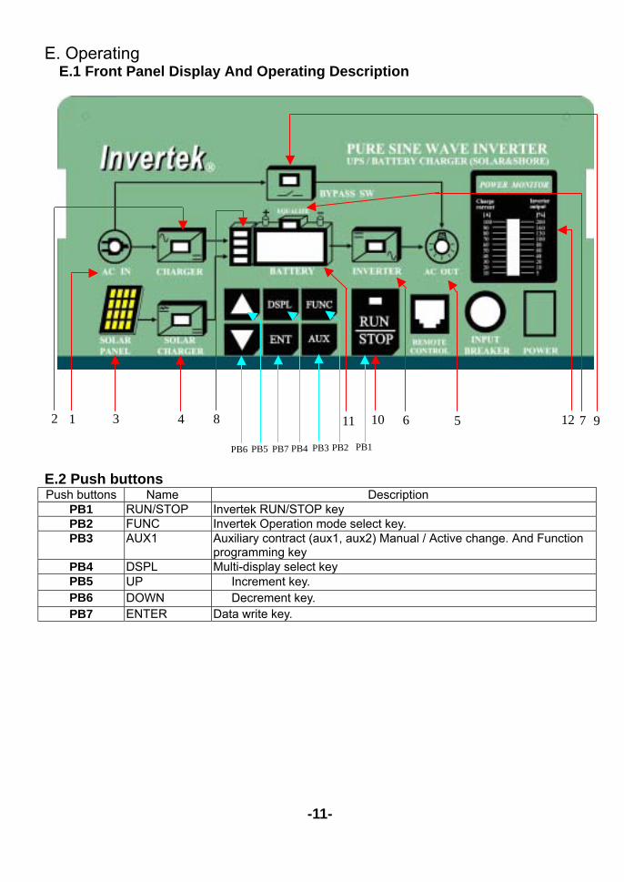
E. Operating E.1 Front Panel Display And Operating Description
E.2 Push buttons Push buttons Name Description
PB1 RUN/STOP Invertek RUN/STOP key PB2 FUNC Invertek Operation mode select key. PB3 AUX1 Auxiliary contract (aux1, aux2) Manual / Active change. And Function
programming key PB4 DSPL Multi-display select key PB5 UP(△) △ Increment key. PB6 DOWN (▽) ▽ Decrement key. PB7 ENTER Data write key.
-11-
12 7 9 6 5 10 11 8 4 3 1 2
PB6 PB5 PB7 PB4 PB3 PB2 PB1
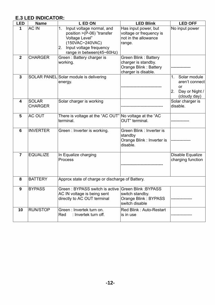
E.3 LED INDICATOR: LED Name L ED ON LED Blink LED OFF
1 AC IN 1. Input voltage normal, and position >(P-06) ”transfer Voltage Level” (150VAC~240VAC)
2. Input voltage frequency range in between(45~60Hz)
Has input power, but voltage or frequency is not in the allowance range.
No input power
2 CHARGER Green : Battery charger is working.
Green Blink : Battery charger is standby. Orange Blink : Battery charger is disable.
--------------
3 SOLAR PANEL Solar module is delivering energy.
-----------------------------
1. Solar module aren’t connect or
2. Day or Night / (cloudy day)
4 SOLAR CHARGER
Solar charger is working ------------------------------
Solar charger is disable.
5 AC OUT There is voltage at the “AC OUT” terminal.
No voltage at the “AC OUT” terminal.
-------------
6 INVERTER Green : Inverter is working. Green Blink : Inverter is standby Orange Blink : Inverter is disable.
--------------
7 EQUALIZE In Equalize charging Process
------------------------------
Disable Equalize charging function
8 BATTERY Approx state of charge or discharge of Battery.
9 BYPASS Green : BYPASS switch is active AC IN voltage is being sent directly to AC OUT terminal
Green Blink :BYPASS switch standby. Orange Blink : BYPASS switch disable
---------------
10 RUN/STOP Green : Invertek turn on. Red : Invertek turn off.
Red Blink : Auto-Restart is in use
---------------
-12-
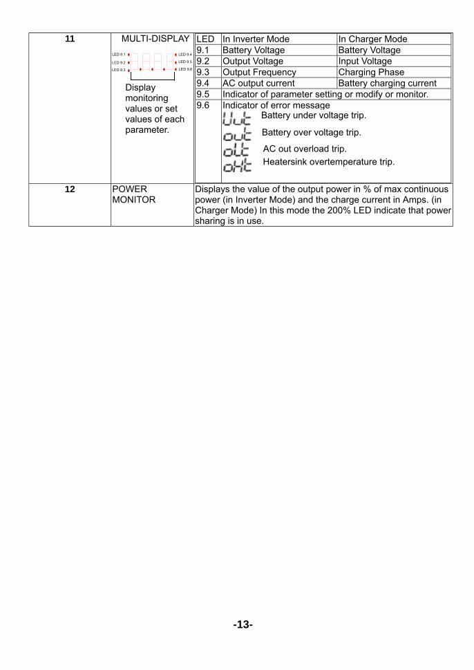
11 MULTI-DISPLAY
LED In Inverter Mode In Charger Mode 9.1 Battery Voltage Battery Voltage 9.2 Output Voltage Input Voltage 9.3 Output Frequency Charging Phase 9.4 AC output current Battery charging current 9.5 Indicator of parameter setting or modify or monitor. 9.6 Indicator of error message
12 POWER
MONITOR Displays the value of the output power in % of max continuous power (in Inverter Mode) and the charge current in Amps. (in Charger Mode) In this mode the 200% LED indicate that power sharing is in use.
-13-
LED 9.4
LED 9.5
LED 9.6
LED 9.1
LED 9.3
LED 9.2
Display monitoring values or set values of each parameter.
:Battery under voltage trip.
:Battery over voltage trip.
:AC out overload trip. :Heatersink overtemperature trip.
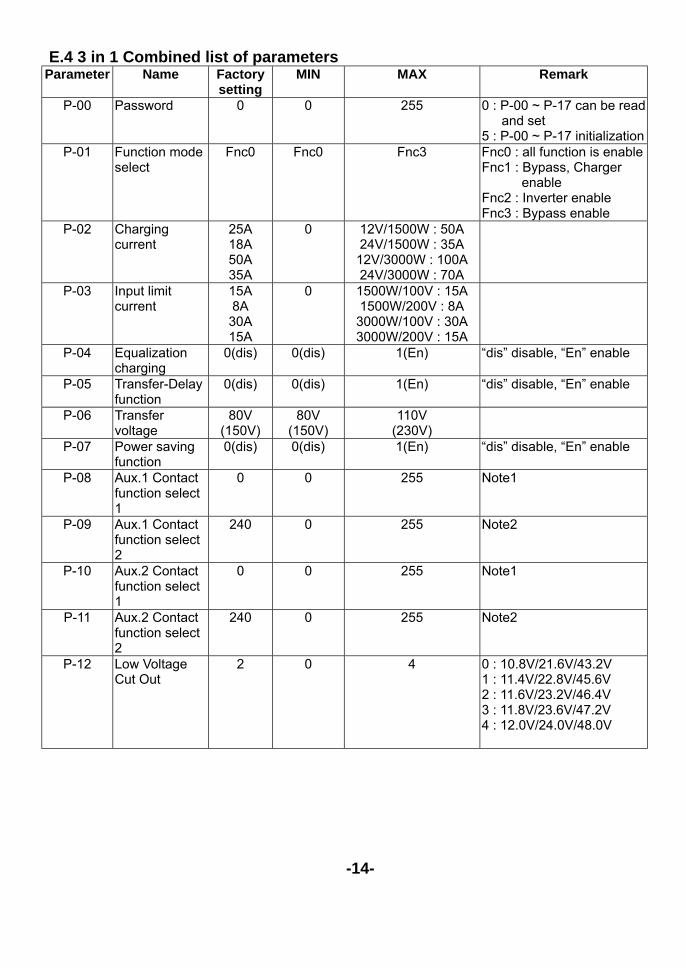
E.4 3 in 1 Combined list of parameters Parameter Name Factory
setting MIN MAX Remark
P-00 Password 0 0 255 0 : P-00 ~ P-17 can be read and set
5 : P-00 ~ P-17 initialization P-01 Function mode
select Fnc0 Fnc0 Fnc3 Fnc0 : all function is enable
Fnc1 : Bypass, Charger enable
Fnc2 : Inverter enable Fnc3 : Bypass enable
P-02 Charging current
25A 18A 50A 35A
0 12V/1500W : 50A 24V/1500W : 35A 12V/3000W : 100A 24V/3000W : 70A
P-03 Input limit current
15A 8A 30A 15A
0 1500W/100V : 15A 1500W/200V : 8A 3000W/100V : 30A 3000W/200V : 15A
P-04 Equalization charging
0(dis) 0(dis) 1(En) “dis” disable, “En” enable
P-05 Transfer-Delay function
0(dis) 0(dis) 1(En) “dis” disable, “En” enable
P-06 Transfer voltage
80V (150V)
80V (150V)
110V (230V)
P-07 Power saving function
0(dis) 0(dis) 1(En) “dis” disable, “En” enable
P-08 Aux.1 Contact function select 1
0 0 255 Note1
P-09 Aux.1 Contact function select 2
240 0 255 Note2
P-10 Aux.2 Contact function select 1
0 0 255 Note1
P-11 Aux.2 Contact function select 2
240 0 255 Note2
P-12 Low Voltage Cut Out
2 0 4 0 : 10.8V/21.6V/43.2V 1 : 11.4V/22.8V/45.6V 2 : 11.6V/23.2V/46.4V 3 : 11.8V/23.6V/47.2V 4 : 12.0V/24.0V/48.0V
-14-
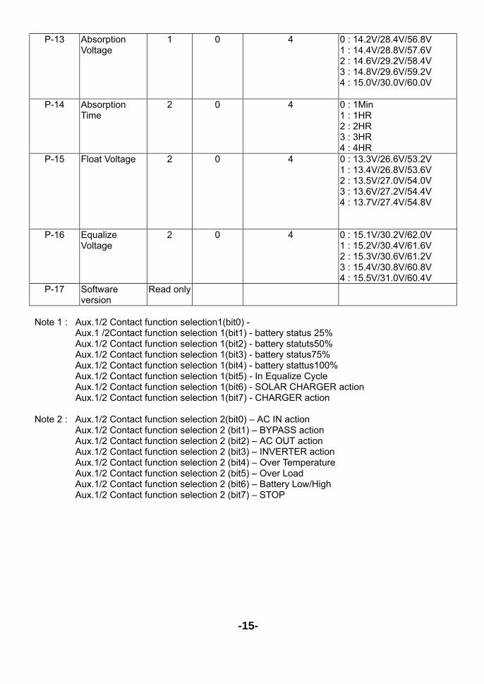
P-13 Absorption Voltage
1 0 4 0 : 14.2V/28.4V/56.8V 1 : 14.4V/28.8V/57.6V 2 : 14.6V/29.2V/58.4V 3 : 14.8V/29.6V/59.2V 4 : 15.0V/30.0V/60.0V
P-14 Absorption Time
2 0 4 0 : 1Min 1 : 1HR 2 : 2HR 3 : 3HR 4 : 4HR
P-15 Float Voltage 2 0 4 0 : 13.3V/26.6V/53.2V 1 : 13.4V/26.8V/53.6V 2 : 13.5V/27.0V/54.0V 3 : 13.6V/27.2V/54.4V 4 : 13.7V/27.4V/54.8V
P-16 Equalize Voltage
2 0 4 0 : 15.1V/30.2V/62.0V 1 : 15.2V/30.4V/61.6V 2 : 15.3V/30.6V/61.2V 3 : 15.4V/30.8V/60.8V 4 : 15.5V/31.0V/60.4V
P-17 Software version
Read only
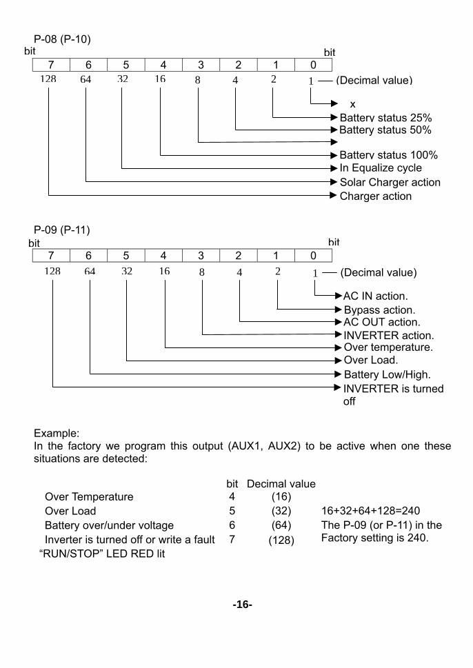
Note 1 : Aux.1/2 Contact function selection1(bit0) - Aux.1 /2Contact function selection 1(bit1) - battery status 25% Aux.1/2 Contact function selection 1(bit2) - battery statuts50% Aux.1/2 Contact function selection 1(bit3) - battery status75% Aux.1/2 Contact function selection 1(bit4) - battery stattus100% Aux.1/2 Contact function selection 1(bit5) - In Equalize Cycle Aux.1/2 Contact function selection 1(bit6) - SOLAR CHARGER action Aux.1/2 Contact function selection 1(bit7) - CHARGER action Note 2 : Aux.1/2 Contact function selection 2(bit0) – AC IN action Aux.1/2 Contact function selection 2 (bit1) – BYPASS action Aux.1/2 Contact function selection 2 (bit2) – AC OUT action Aux.1/2 Contact function selection 2 (bit3) – INVERTER action Aux.1/2 Contact function selection 2 (bit4) – Over Temperature Aux.1/2 Contact function selection 2 (bit5) – Over Load Aux.1/2 Contact function selection 2 (bit6) – Battery Low/High Aux.1/2 Contact function selection 2 (bit7) – STOP
-15-
P-08 (P-10)
7 6 5 4 3 2 1 0
P-09 (P-11)
7 6 5 4 3 2 1 0
Example: In the factory we program this output (AUX1, AUX2) to be active when one these situations are detected:
bit Decimal value ˙Over Temperature 4 (16) ˙Over Load 5 (32) 16+32+64+128=240 ˙Battery over/under voltage 6 (64) ˙Inverter is turned off or write a fault “RUN/STOP” LED RED lit
7
(128)
The P-09 (or P-11) in the Factory setting is 240.
-16-
bit bit
128 64 32 16 8 1 2 4 (Decimal value)
x Battery status 25% Battery status 50% Battery status 100% In Equalize cycle Solar Charger action Charger action
bit bit
128 64 32 16 8 1 2 4 (Decimal value)
AC IN action. Bypass action. AC OUT action. INVERTER action. Over temperature. Over Load. Battery Low/High. INVERTER is turned off
E.5 Function selection setting 【1】Press ”FUNC” key and hold for 2sec, Multi-Display will shows the current setting 【2】Press ”UP”,”DOWN” key to choice the function (Fnc0,Fnc1,Fnc2,Fnc3)
【3】Press ”DSPL” key for Multi-Display back to monitoring battery voltage or 20sec without press any key for automatically back to normal
E.6 Aux.1/2 Contact function selection setting E.6.1 Aux.1/2 Contact Auto/ Manual ON,OFF operating instruction
【1】Press ”AUX1” key after, Multi-Display will shows the current status of AUX.1 or AUX.2, “1Aon” – AUX.1 Current function in Auto mode, connection point close “1AoF” – AUX.1 Current function in Auto mode, connection point open “1Hon” – AUX.1 Current function in Manual mode, connection point close “1HoF” – AUX.1 Current function in Manual mode, connection point open “2Aon” – AUX.2 Current function in Auto mode, connection point close “2AoF” – AUX.2 Current function in Auto mode, connection point open “2Hon” – AUX.2 Current function in Manual mode, connection point close “2HoF” – AUX.2 Current function in Manual mode, connection point open 【2】Press ”UP”,”DOWN” key to choice AUX.1 or AUX.2 【3】Press ”AUX1” key to choice connection point to be open or close 【4】Press ”DSPL” key Multi-Display back to monitoring battery voltage , or without press
any key for 20secto be automatically back to normal E.6.2 Aux.1/2 connect point action operating instruction Invertek 3 in 1 combined can planning connect point action are conditions as below:
1. Battery status 25%,50%,75%,100% 2. In Equalize Cycle 3. SOLAR CHARGER in action 4. CHARGER in action 5. AC IN action 6. BYPASS action 7. AC OUT action 8. INVERTER action 9. Over Temperature 10. Over Load 11. Battery Low/High 12. STOP
Operating instruction 【1】 Press ”AUX” Key and hold for about 2sec, Multi-Display will display the
current status of AUX. Contact “ry-1” it means AUX1; “ry-2” it means AUX2 【2】 Press ”UP”,”DOWN” to choice the AUX you have planned. 【3】 Press ”ENTER” Key after the Multi-Display will shows the current status of
what you have been planned connect point action condition detail. at meantime when LED flash, it means the condition has settled
【4】 Press ”UP”,”DOWN” key to choice above condition for your planning 【5】 Press ”AUX” key to decide whether the condition has settled (Multi-Display
shows 0:Relieve ,1: Set up) 【6】 Press ”DSPL” Key Multi-Display will back to monitoring battery voltage, or
without press any key for 20secto be automatically back to normal
-17-
E.7.1 The Inverter The Inverter section of the Invertek produces a high quality Sinewave output, the quality of this output is compatible with any appliance, Thanks to the generous dimensioning of the Invertek, you can operate appliances requiring higher power than the nominal power of the Invertek for a short time. The Invertek provide up to 3-times the nominal power to start motors etc. E.7.2 Power saving function (P-07) In order to avoid unnecessary discharge of the battery, the inverter switches OFF automatically if no AC power is being used. The Invertek switches ON automatically again if an AC load is switched ON. The AC Out LED blinks if the inverter is in “Power Saving-Mode”. The switching-ON threshold can be set P-07 “ENABLE” function. If the “Power Saving-Mode” is not wanted, set the P-07 “DISABLE” function, this will keep the Invertek running continuously, but will also discharge your batteries quicker. E.7.3 Overload If the Invertek is overloaded for too long or too heavily, it switches off. The “Multi-display” will show “ ” and the “RUN/STOP” LED will RED Blink. After approximately 10 seconds the Inverter switches on automatically. If the Inverter is overloaded four times in quick succession, then it no longer switches back on automatically. The “RUN/STOP” LED remains lit, and the multi-display show “ ”. Press the push button 1(PB1) ”RUN/STOP” in order to switch the Inverter back ON. E.7.4 Overheating (Over Temp) If the Inverter has been overload for a long time or it has been working in a high ambient temperature, it will switch OFF. The “Multi-display” will show “ ” and the “RUN/STOP”LED RED blinks. After cooling down, the inverter switches back on automatically. One minute before the inverter switches off due to high temperature a buzzer will be heard. If the Auxiliary Contact has been programmed for “Over Temp” then the contact will be active when the buzzer sounds. This could be used for example to start an emergency back up generator, creating a no break energy supply.
-18-
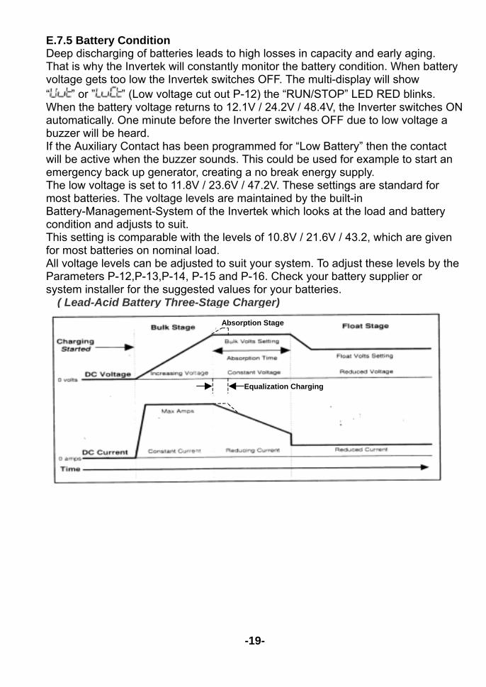
E.7.5 Battery Condition Deep discharging of batteries leads to high losses in capacity and early aging. That is why the Invertek will constantly monitor the battery condition. When battery voltage gets too low the Invertek switches OFF. The multi-display will show “ ” or ” ” (Low voltage cut out P-12) the “RUN/STOP” LED RED blinks. When the battery voltage returns to 12.1V / 24.2V / 48.4V, the Inverter switches ON automatically. One minute before the Inverter switches OFF due to low voltage a buzzer will be heard. If the Auxiliary Contact has been programmed for “Low Battery” then the contact will be active when the buzzer sounds. This could be used for example to start an emergency back up generator, creating a no break energy supply. The low voltage is set to 11.8V / 23.6V / 47.2V. These settings are standard for most batteries. The voltage levels are maintained by the built-in Battery-Management-System of the Invertek which looks at the load and battery condition and adjusts to suit. This setting is comparable with the levels of 10.8V / 21.6V / 43.2, which are given for most batteries on nominal load. All voltage levels can be adjusted to suit your system. To adjust these levels by the Parameters P-12,P-13,P-14, P-15 and P-16. Check your battery supplier or system installer for the suggested values for your batteries.
( Lead-Acid Battery Three-Stage Charger)
-19-
Absorption Stage
Equalization Charging
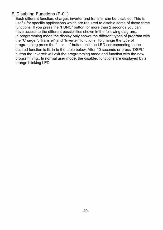
F. Disabling Functions (P-01) Each different function, charger, inverter and transfer can be disabled. This is useful for specific applications which are required to disable some of these three functions. If you press the “FUNC” button for more than 2 seconds you can have access to the different possibilities shown in the following diagram,. In programming mode the display only shows the different types of program with the “Charger”, Transfer” and “Inverter” functions. To change the type of programming press the “△or ▽” button until the LED corresponding to the desired function is lit, in to the table below, After 10 seconds or press “DSPL” button the Invertek will exit the programming mode and function with the new programming,. In normal user mode, the disabled functions are displayed by a orange blinking LED.
-20-
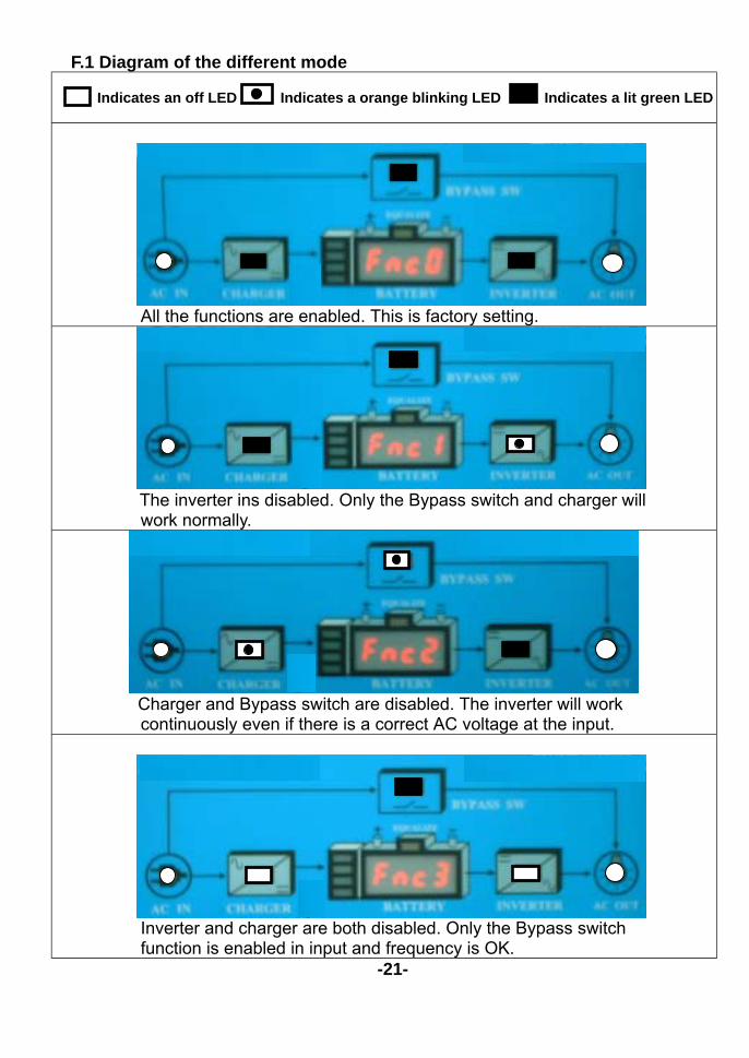
F.1 Diagram of the different mode
Indicates an off LED Indicates a orange blinking LED Indicates a lit green LED
All the functions are enabled. This is factory setting.
The inverter ins disabled. Only the Bypass switch and charger will
work normally.
Charger and Bypass switch are disabled. The inverter will work
continuously even if there is a correct AC voltage at the input.
Inverter and charger are both disabled. Only the Bypass switch
function is enabled in input and frequency is OK. -21-
G. Charger Information G.1.1 Charging Cycle The fully automatic Invertek Battery Charger is adjusted at the factory so that most lead-acid and lead-gel batteries can be charged to the maximum, As soon as the minimum AC voltage is available at the AC input (“AC IN” LED is lit),the Battery Charger is switched on automatically (“CHARGER” LED is lit). The battery is automatically charged to match the pre adjusted voltage levels and charge current. Thanks to the Invertek sophisticated and intelligent Floating Charge System, the batteries can be left in charge mode for unlimited time. During the charging cycle, the AC loads are continually supplied with power from the incoming AC voltage source. (“AC OUT” LED is lit). The charger functions are shown in the following diagram: G.1.2 Equalization charging (P-04): Equalization charge is a higher voltage applied to the batteries for a specified period of time.
Equalization mode should never be used when using Gel-Batteries Before you program the Invertek for Equalization-charge you must confirm with your supplier that the batteries are suitable for this process. Equalization is recommended for lead-acid batteries in order to mix the electrolyte fluid and to clean the lead plates of the batteries. If the Invertek is operating with a lead-acid battery which is suitable for equalization, set the P-04 is “ENABLE”. In this setting, at every 25 charge cycles an equalization cycle will be carried out for 2 hours (factory setting). During such a charge cycle the “Equalize” LED lit. During a Charge cycle, equalization can be started independent of the actual programming. CAUTION: During the equalization process, the batteries will produce a lot more gas.
DANGER OF N EXPLOSION!! G.1.3 Input current repartition (Power sharing) To manage the power available on the AC INPUT the Invertek is equipped with a system usually called “Power sharing” or INPUT power distribution. With this feature it is possible to limit the AC INPUT current assigned to the charger. The more current used by the AC load, the less power is given to the charger. Priority for the AC Loads. When power sharing is used the red 200% LED on the power monitor is lit to show that the battery charging is being limited.
-22-
Set the INPUT LIMIT (P-03) The current available to the Invertek depends on the source of the AC input supply, i.e. motor generator, limited grid supply in a caravan park or shore power. The value of the “INPUT LIMIT” P-03 adjustment must be lower or equal to the current available from the AC Input source. For example if you have a generator of 2kW you must adjust the “Input limit” to approximately 8.5A. To calculate this, divide the nominal power of the AC input source (2000W) by the voltage (230V). If the circuit breaker before the Invertek is lower than this value, then you must set the “Input Limit” to the value of the circuit breaker.
Generator power Current (230V) 500W 2A 900W 4A
1500W 6,5A 2000W 8,5A 3000W 13A
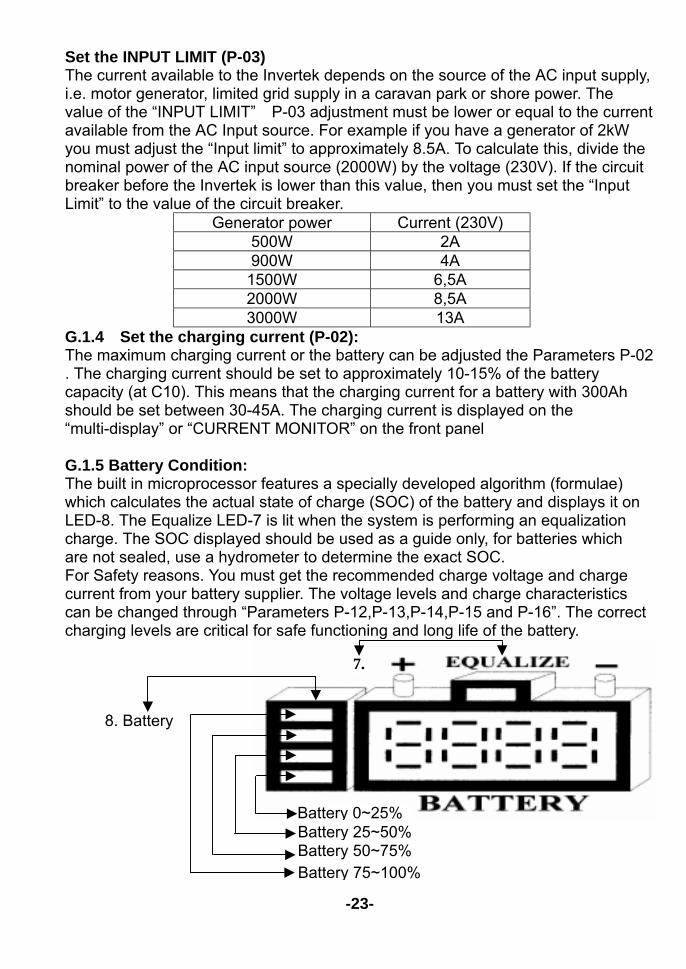
G.1.4 Set the charging current (P-02): The maximum charging current or the battery can be adjusted the Parameters P-02 . The charging current should be set to approximately 10-15% of the battery capacity (at C10). This means that the charging current for a battery with 300Ah should be set between 30-45A. The charging current is displayed on the “multi-display” or “CURRENT MONITOR” on the front panel G.1.5 Battery Condition: The built in microprocessor features a specially developed algorithm (formulae) which calculates the actual state of charge (SOC) of the battery and displays it on LED-8. The Equalize LED-7 is lit when the system is performing an equalization charge. The SOC displayed should be used as a guide only, for batteries which are not sealed, use a hydrometer to determine the exact SOC. For Safety reasons. You must get the recommended charge voltage and charge current from your battery supplier. The voltage levels and charge characteristics can be changed through “Parameters P-12,P-13,P-14,P-15 and P-16”. The correct charging levels are critical for safe functioning and long life of the battery.
-23-
Battery 0~25% Battery 25~50% Battery 50~75% Battery 75~100%
8. Battery
7.
G.2 The Transfer system (P-06) When an AC voltage is present at the AC IN of the Invertek, the “AC IN” LED is lit. When this voltage matches the Parameter P-06 value set, and the frequency is between 44Hz and 65Hz, then this power is transferred directly to the AC load and the battery charger section of the Invertek. The “TRANSFER” LED is lit to indicate this has happened. The inverter is then switched off and the battery charger switched on. This process is automatic and should not be noticed by the load, at worst a slight flicker may be seen in lights. The maximum current of the Bypass switch is (60A/DAI-3000C-xxxx) or (30A/DAI-1500C-xxxx). That means through this system. AC loads of up to a maximum 7000 W (DAI-3000C-xxxx) or 3500W (DAI-1500C-xxxx) can be operated. When the Battery Charger is working, part of this power is used for the charging according to the power sharing settings. The Transfer system is protected against overload with an automatic breaker on the AC Input side of the Invertek. If the system has been overloaded the Input breaker will pop-out. To put the automatic safety system back in to operating you must push this breaker for reset. Note: In Inverter operation, The Invertek generates a True Sinewave and quartz stabilized output voltage. However, when the Invertek is transferring power from the grid or a generator the voltage and quality of the power running the AC load will be the same as that coming from the grid or generator. The Invertek cannot modify the incoming AC supply. Setting the transfer voltage threshold (P-06) The voltage threshold of the transfer can be adjusted between 150 to 230V with the Parameter P-06. This value is set at 150V AC in the factory. The majority of appliances can work on this voltage. When the Input voltage reaches the selected value on the P-06, the inverter switches off and the AC INPUT goes directly to the AC OUTPUT. When the voltage INPUT is 20V less than the value set, the transfer of power is stopped and the OUTPUT is switched back to the inverter. G.3 The Solar charge regulator (option) The Invertek has an optional built in Solar Charge Regulator. To charge the batteries, Solar modules can be connected to the terminal SOLAR IN +/-. The in-built regulator is a Shunt regulator with a maximum input current of 30A for all series products. The operating voltage of Solar modules to be connected must match the actual operating voltage of the Invertek and never exceed the max. rated value.
-24-

Under no circumstances should any other charging sources such as a wind-generator be connected at the input of the Solar Charge Regulator. The Solar Charge Regulator works automatically and is always in operation. As soon as the energy is delivered from the Solar Charge Regulator, the “SOLAR CHARGE” LED is lit and the batteries are being charged, The Solar Charge Regulator works even when the Battery Charger is functioning. The method of operation is a 3 or 4 step charging process, the same as the battery charger. The function is described in the section on Battery Charger. The programming and the adjustments are carried out in accordance with the section on Battery Charger. The programming and the adjustments are carried out in accordance with the same conditions. Check with your battery supplier which adjustments must be carried out for your battery.
-25-
H. Power Sharing H.1.1 FAST (UPS)-MODE for the Bypass switch (P-05”DISABLE”) The quick and almost break free Transfer mode is programmed with the Parameter P-05 set “DISABLE”. The aim of the Invertek is to supply the AC loads with a break-free AC voltage. When the incoming voltage AC IN no longer matches values which have been set with the “P-06”, the Invertek switches back to Inverter. The transfer is carried out in 0.02 seconds. This quick transfer ensures a break-free function for most AC loads. If AC voltage is restored at the AC Input which is within the set parameters then the transfer of power will resume, again with only 0.02 seconds transfer time. H.1.2 DELAY MODE for the Bypass switch (P-05”ENABLE”) The delayed mode of the Bypass switch, the Parameter-05 set “ENABLE” and then the Invertek provides a break-free alternating voltage for the consuming device. A quick transfer switch is not always sensible nor is it always desired. For example, when the consuming devices are operated by a small back-up generator. An overload of a short duration on such a generator, i.e. start of a vacuum cleaner etc., has the effect of decreasing the voltage for a short time. As in such cases the transfer to the Inverter is not desirable, the Bypass switch can be programmed with a delay. The inverter takes place with a delay of 5 seconds. If the voltage falls below 100Vac (220V) or 50VAC (110V) the transfer takes place without delay! The transfer switching to the Inverter takes place without any break.
-26-
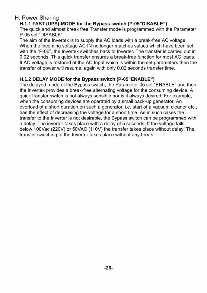
I. Auxiliary Contacts In the Invertek there are two built-in programmable power relay (AUX1, AUX2). The potential-free change-over contact of this power relay is connected to the screw terminals (AUX1 NO-NC-COM, AUX2 NO-NC-COM) Maximum Contact load: -230Vac / 5Amp-30Vdc/7Amp In the factory we program this output to be active when one these situations are detected: Over temperature Overload Over or under voltage of batteries Invertek is turned off manually or with a fault, “RUN/STOP” LED RED lit
-27-
Over / Under Voltage of Batteries. AC output overload. Invertek over temperature.
J. The Remote control unit As an option, a Remote control unit can be connected to the Invertek. All operating controls and displays are available on the Remote control unit, The Remote control is supplied with a 3m long cable. It can be lengthened to 15m The Remote control is suitable for surface mounting on the wall or on to a switch board. It is fixed with 2 screws. The Invertek can also be programmed with the Remote control. The output currents and the charging currents are displayed on the Remote control. J.1 The Temperature sensor Charging voltages of lead-acid batteries can change depending on temperature. To correct the operating voltages according to the actual temperatures, a temperature sensor can be connected to the Invertek. The compensation through the sensor is -3mv/℃/Cell.
-28-
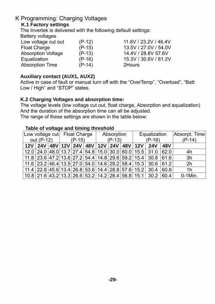
K Programming: Charging Voltages K.1 Factory settings The Invertek is delivered with the following default settings: Battery voltages
Low voltage cut out (P-12) 11.6V / 23.2V / 46.4V Float Charge (P-15) 13.5V / 27.0V / 54.0V Absorption Voltage (P-13) 14.4V / 28.8V 57.6V Equalization (P-16) 15.3V / 30.6V / 61.2V Absorption Time (P-14) 2Hours
Auxiliary contact (AUX1, AUX2) Active in case of fault or manual turn off with the “OverTemp”, “Overload”, “Batt
Low / High” and “STOP” states. K.2 Charging Voltages and absorption time: The voltage levels (low voltage cut out, float charge, Absorption and equalization)
And the duration of the absorption time can all be adjusted. The range of these settings are shown in the table below:
Table of voltage and timing threshold Low voltage cut
out (P-12) Float Charge
(P-15) Absorption
(P-13) Equalization
(P-16) Absorpt. Time
(P-14) 12V 24V 48V 12V 24V 48V 12V 24V 48V 12V 24V 48V 12.0 24.0 48.0 13.7 27.4 54.8 15.0 30.0 60.0 15.5 31.0 62.0 4h 11.8 23.6 47.2 13.6 27.2 54.4 14.8 29.6 59.2 15.4 30.8 61.6 3h 11.6 23.2 46.4 13.5 27.0 54.0 14.6 29.2 58.4 15.3 30.6 61.2 2h 11.4 22.8 45.6 13.4 26.8 53.6 14.4 28.8 57.6 15.2 30.4 60.8 1h 10.8 21.6 43.2 13.3 26.6 53.2 14.2 28.4 56.8 15.1 30.2 60.4 0-1Min.
-29-
L. Programming Aux Contacts (AUX1, AUX2) L.1.1 Principle The Auxiliary Invertek can be basically programmed for any operating situation of
the Invertek which is indicated with a LED. The programming is possible for one or more operating situations. If the contact is programmed for many situations, it is activated as soon as the Invertek finds itself in any one of the programmed situations. L.1.2 Example
L.1.2.1 Auxiliary contact as generator starter When in the programming of the Auxiliary Contact, the State of Charge (SOC)
LED`s (LED 8) can be used as a condition, then you must take note of the following requirements. If you have to start an emergency back-up supply with a battery having a certain SOC, then two SOC levels must be programmed. The first (i.e. Battery 25% LED) for the starting or activating the Auxiliary Contact and the second (i.e. Battery 100% LED ) for stopping or deactivating the Auxiliary Contact. By programming in this way the Auxiliary Contact starts with the lowest set condition and stops when it has reached the highest programmed condition through charging. L.1.2.2 Auxiliary Contact as Twilight Switch (With solar charger option) The Auxiliary Contact of the Invertek can also be used as a twilight switch , i.e. for automatically operating exterior lighting. Solar modules connected to the Invertek will measure the light intensity. If the invertek is operating without solar modules and a twilight-switching function is desired, you can connect small solar cells with the nominal voltage of the Invertek to the SOLAR terminals for the purpose of measuring the light intensity. To function as a twilight-switch the Auxiliary Contact must be programmed so that the condition “SOLAR CHARGE” LED is active. Programming must be carried out in steps and in accordance with the description for the programming of the Auxiliary Contact. L.1.3.3 Manual operating of Auxiliary Contact: The Auxiliary Contact can be operated manually at any time by pressing the “AUX” button. The “Multi-display show ( ) to indicate that the Contact is manually operated. By pushing the “AUX CONTACT” button again ,the Contact is deactivated. Multi-display show ( ). By pushing it a third time, automatic functions are restored and Multi-display show ( ).
-30-
M. Maintenance Periodic maintenance is important to avoid potential problems. Every six months
disconnect all power in and out from the system. Thoroughly clean and check all battery connections within the battery bank and to the Invertek. Ensure all connections to the Invertek are tight. Ensure the vents at the top and bottom of the Invertek are clear of any debris, such as mud wasps, severe dust build ups etc.
Other than this, you should enjoy years of trouble free operation form your Invertek.
-31-
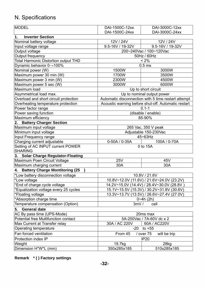
N. Specifications MODEL DAI-1500C-12xx
DAI-1500C-24xx DAI-3000C-12xx DAI-3000C-24xx
1. Inverter Section Nominal battery voltage 12V / 24V 12V / 24V Input voltage range 9.5-16V / 19-32V 9.5-16V / 19-32V Output voltage 200~240Vac / 100~120Vac Output frequency 50Hz / 60Hz Total Harmonic Distortion output THD < 2% Dynamic behavior 0→100% 0.5 ms Nominal power (W) 1500W 3000W Maximum power 30 min (W) 1700W 3500W Maximum power 3 min (W) 2300W 4500W Maximum power 5 sec (W) 3000W 6000W Maximum load Up to short circuit Asymmetrical load max. Up to nominal output power Overload and short circuit protection Automatic disconnection with 5 time restart attempt Overheating temperature protection Acoustic warning before shut-off. Automatic restart Power factor range 0.1-1 Power saving function (disable / enable) Maximum efficiency 85-90% 2. Battery Charger Section Maximum input voltage 265 Vac, 350 V peak Minimum input voltage Adjustable 150-230Vac Input Frequency range 45~63Hz Charging current adjustable 0-50A / 0-35A 100A / 0-70A Setting of AC INPUT current POWER SHARING
0 to 15A
3. Solar Charge Regulator-Floating Maximum Poen Circuit Voltage 25V 45V Maximum charging current 30A 30A 4. Battery Charge Montitoring (25℃) *Low battery disconnection voltage 10.8V / 21.6V *Low voltage 10.8V~12.0V (11.6V) / 21.6V~24.0V (23.2V) *End of charge cycle voltage 14.2V~15.0V (14.4V) / 28.4V~30.0V (28.8V ) *Equalization voltage every 25 cycles 15.1V~15.5V (15.3V) / 30.2V~31.8V (30.6V) *Floating voltage 13.3V~13.7V (13.5V) / 26.6V~27.4V (27.0V) *Absorption charge time 0~4h (2h) Temperature compensation (Option) 3mV / ℃ cell 5. General date AC By pass time (UPS-Mode) 20ms max Potential free Multifunction contact 5A-250Vac / 7A-60V dc x 2 Max Current at Transfer relay 30A / AC 220V 60A / AC220V Operating temperature -20℃to +55℃ Fan forced ventilation From 45℃ / over 75℃ will be trip Protection index IP IP20 Weight 19.7kg 28kg Dimension H*W*L (mm) 350x285x185 510x285x185
Remark:* ( ) Factory settings
-32-