Embed Size (px)
Citation preview
3. LYSIMETER AND PERCHED WATER SAMPLING LOCATIONS AND INSTALLATION INFORMATION
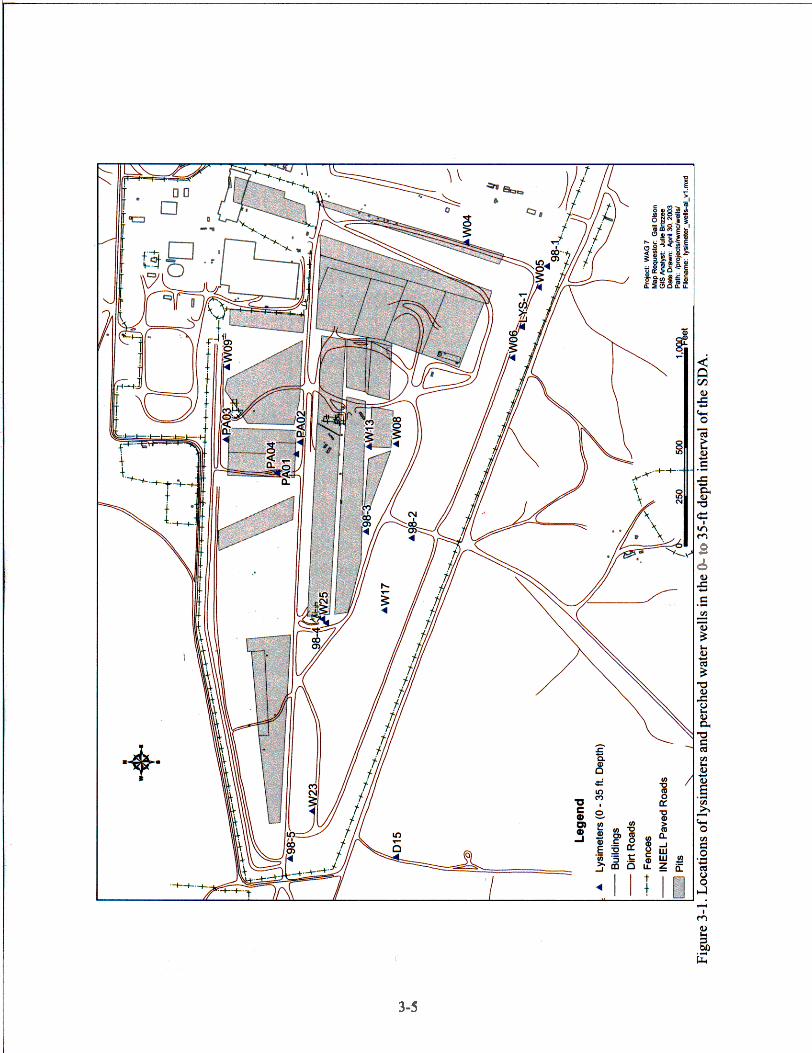
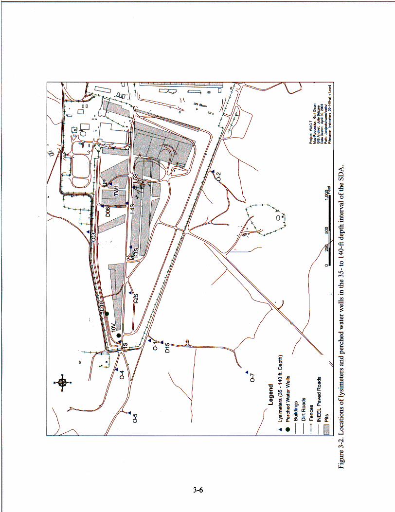
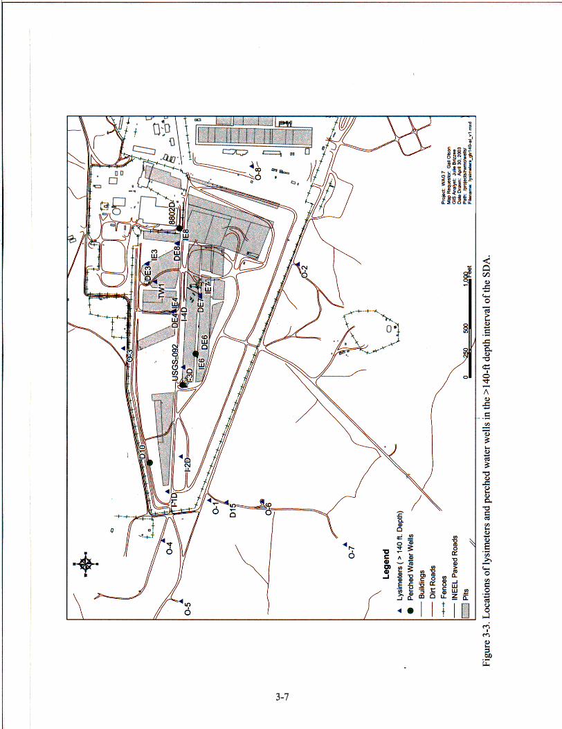
Lysimeter and perched water wells will be sampled routinely in accordance with the guidelines in Section 5 and applicable technical procedures. The current list of active lysimeters is provided in Table 3-1, and the locations of lysimeters and perched water wells are provided in Figures 3-1, 3-2, and 3-3 for the 0- to 3 5 4 , 35- to 1404, and >140-ft depth intervals, respectively. Additional information about the lysimeters, including their construction and original objectives, is provided in the following discussion.
Monitoring of contaminants in soil moisture began with the installation of lysimeters by the Subsurface Investigation Program in 1985. The first lysimeters were installed to characterize solution chemistry and to define radionuclide migration in the vadose zone (Hubbell et al. 1985). Shallow lysimeters were installed in auger holes with silica flour slurry surrounding the lysimeter cup. A 2- to 3-in. layer of bentonite was placed on top of the silica flour as a moisture seal, and native sediments were used to backfill the borehole. Deep lysimeters in the B-C and C-D interbeds were installed in silica flour slurry, and bentonite was used to seal between instrument installations in the same borehole. From 1985 through 1987, 32 suction lysimeters were installed in surficial sediments in and around the RWMC, and seven deep lysimeters were installed in sedimentary interbeds (Hubbell et al. 1985, 1987; Laney et al. 1988).
As part of remediation and monitoring activities for Pad A (Parsons 1995a, 1995b), two lysimeters were installed in December 1994. Lysimeter L33 was installed at a depth of 10 ft below land surface on the north side of Pad A in borehole PA03 (see Figure 3-1). Pad A is an aboveground disposal area located on an asphalt pad. However, well logs indicate that drillers did not encounter the asphalt pad when augering borehole PA03; therefore, either the asphalt pad does not extend as far as borehole PA03, or the lysimeter is located in cover material above the asphalt pad. Lysimeter L34 was installed in a horizontal borehole under the asphalt at Pad A in borehole PA04. Lysimeter L34 is located near the center of Pad A, approximately 165 ft northeast of the borehole PA04 wellhead. Both lysimeters were installed in silica flour, and bentonite was used to seal the silica flour layer.
Five lysimeters, L35 through L39, were installed in surficial sediments in the SDA in 1998 to assess magnesium chloride migration in soil at the SDA (see Figure 3-1 and Table 3-1). Magnesium chloride was applied to SDA roads to suppress dust in 1984, in 1985, and in the early 1990s, and the chloride might contribute to the corrosion of buried waste containers (Hull and Bishop 2003). Each of the lysimeters was installed as close as possible to the sedimenthasalt interface. A soil slurry was placed around the porous ceramic cup, native soil was used to backfill the borehole, and a l-ft layer of bentonite was placed 2 ft above the instrument to serve as a barrier to downhole water movement.
Suction lysimeters L40 and L4 1 were installed in 1994 to collect water samples near buried beryllium blocks near the west end of Soil Vault Row (SVR)-20. Lysimeter cups were placed in native fill material with a layer of sand above and below the lysimeter, and the borehole was backfilled with bentonite. Several attempts were made to collect a sample from L40, but a sufficient vacuum to collect a sample could not be maintained. The deeper lysimeter, L4 1, yielded enough sample volume to analyze for chloride, C-14, and tritium (fitter and McElroy 1999).
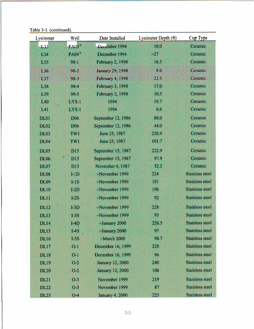
From November 1999 through March 2000,22 deep lysimeters, DL08 through DL29, were installed inside and outside the SDA (Dooley and Higgs 2003) (see Figures 3-2 and 3-3 and Table 3-1). The porous cups on these lysimeters are stainless steel with -600 cm of water air entry pressure. Installation was similar to the procedure described above with silica flour slurry between layers of
3-1
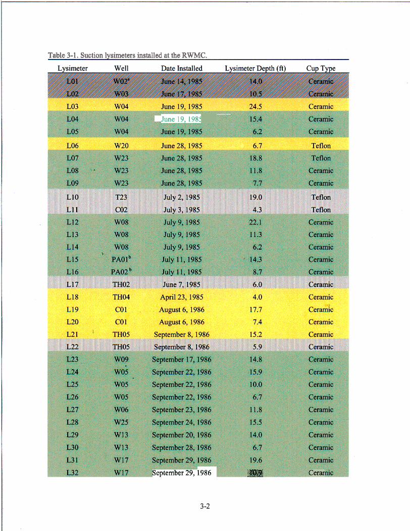
Table 3-1. Suction lysimeters installed at the RWMC.
. . June 19,1982
September 29, 1986 Cerar
3 -2
y"""'
1.33
Y" c - PA0 Decc
3 -3
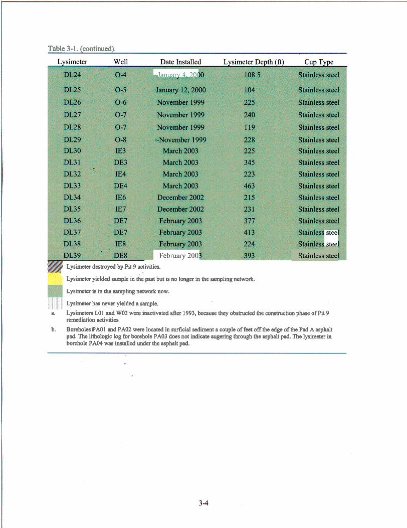
Table 3-1. (continued).
Januarv4 70(
February 200: Lysimeter destroyed by Pit 9 activities.
Lysimeter yielded sample in the past but is no longer in the sampling network.
stee stee
Stainless stee
Lysimeter is in the sampling network now.
Lysimeter has never yielded a sample. Lysimeters LO1 and WOZ were inactivated after 1993, because they obstructed the construction phase of Pit 9 remediation activities.
a.
b. BoreholesPAOl and PA02 wcn located in surticial sediment a wuple of fcct off the edge of the Pad A asphalt pad. The lithologic 108 for borehole PA03 does not indicate augering through the asphalt pad. The lysimeter in borehole PA04 was installed undcr the asphalt pad.
s d
3-5
3-6
I I
3-1

bentonite. Between December 2002 and March 2003, 10 deep lysimeters, DL30 through DL39, were installed in nine wells inside the SDA in a manner similar to that described above. The stainless-steel porous cups of these lysimeters were saturated with distilled water before installation, which needs to be considered when evaluating data from the first round of samples collected from these lysimeters.
The lysimeter and perched water wells will be sampled routinely for the analyses specified in Section 2. All sampling will be conducted using the guidelines provided in Section 5 . Table 3-1 identifies the lysimeters installed and sampled in and around the SDA.
3-8
4. SAMPLE IDENTIFICATION
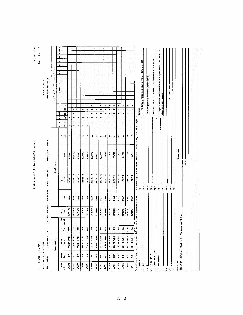
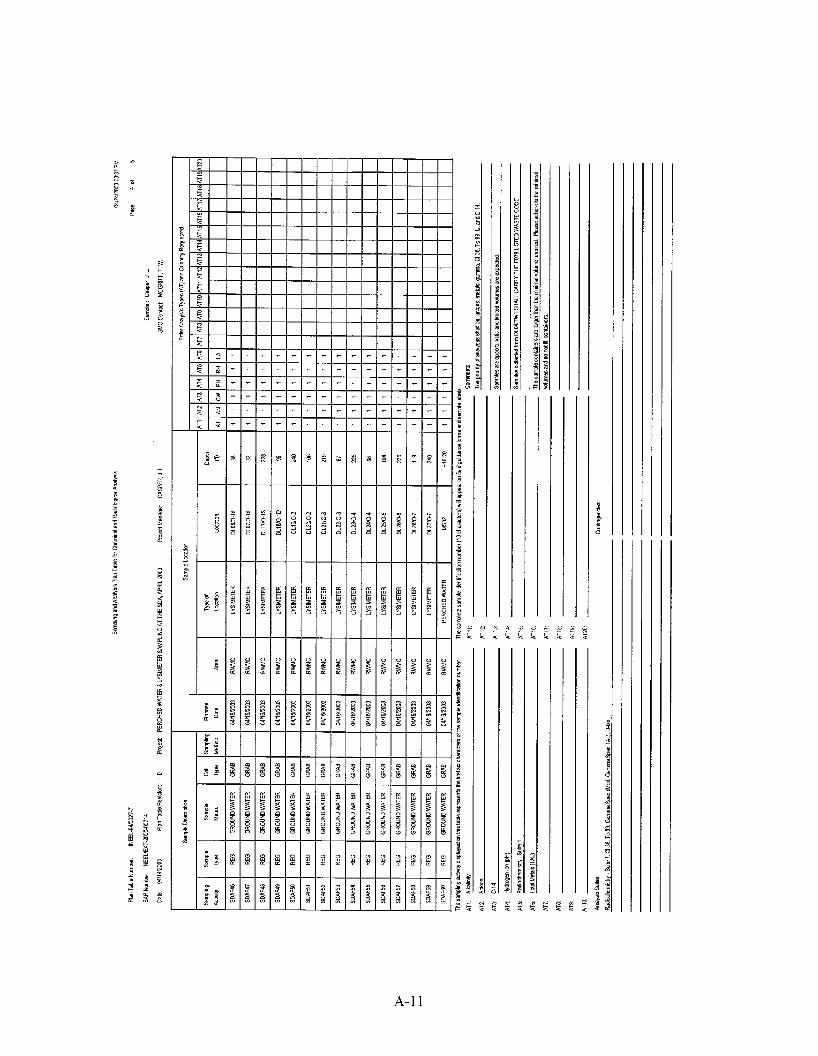
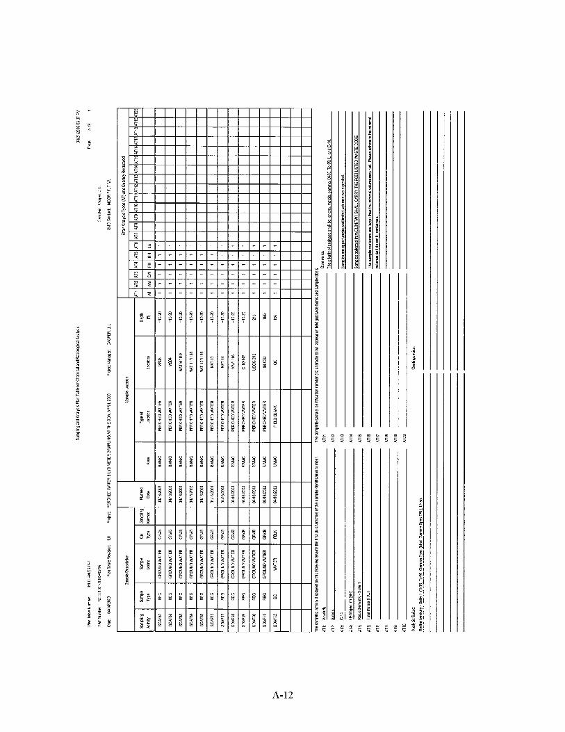
A systematic 10-character sample identification code will be used to uniquely identify all samples. The uniqueness of the number is required to maintain consistency and ensure that no two samples are assigned the same identification code. The sample numbers are assigned by Sampling and Analysis Management (SAM) personnel. The SAM’s database is used to ensure the uniqueness of sample identification.
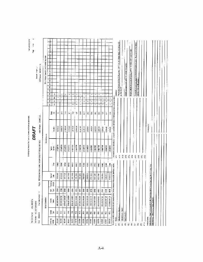
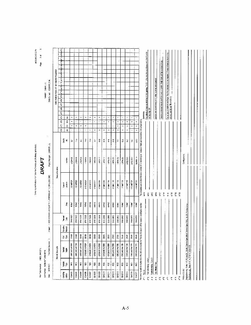
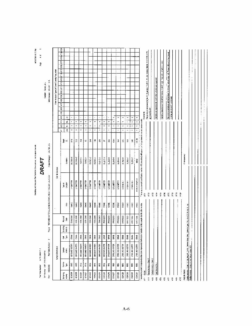
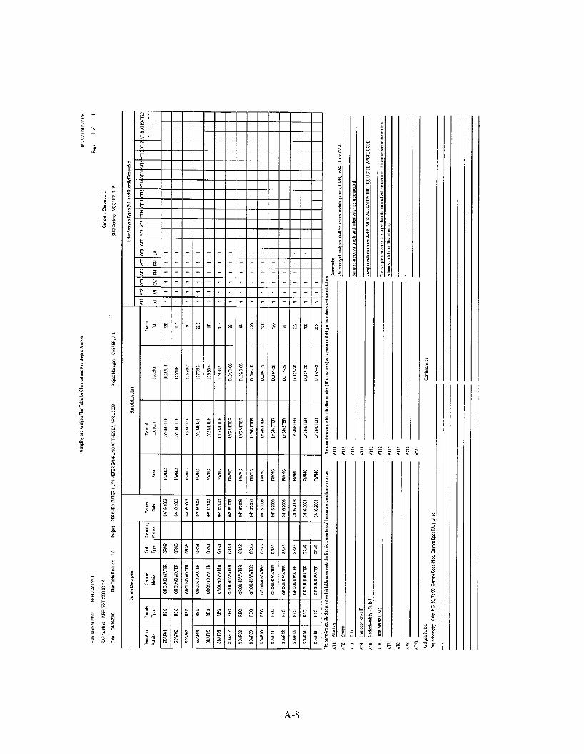
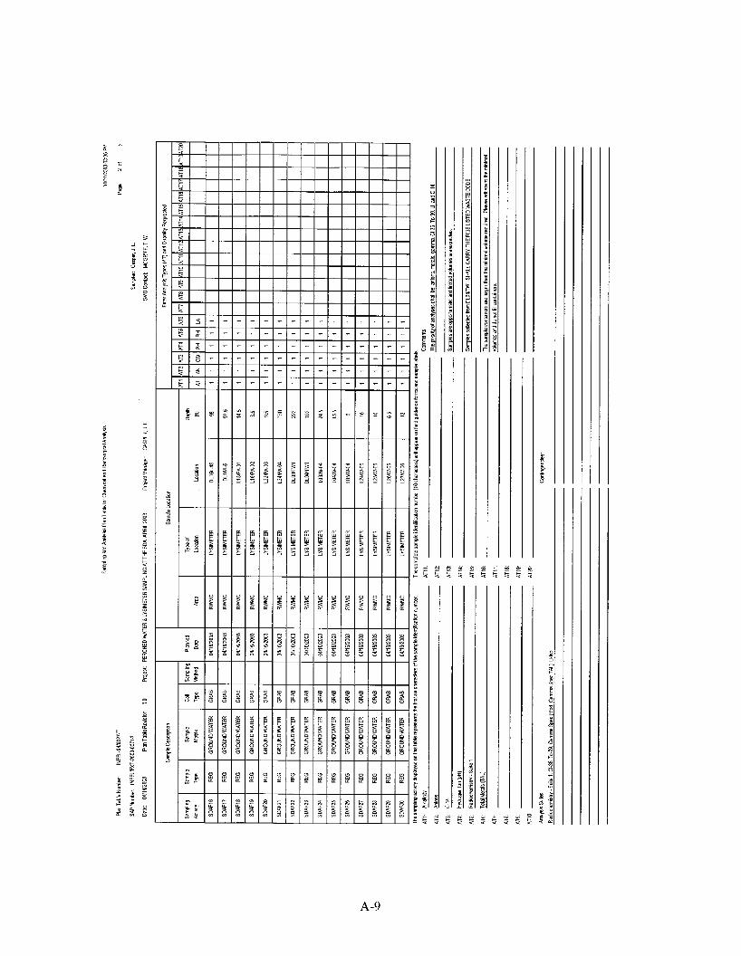
A SAP table format was developed to simplify the presentation of the sampling scheme for project personnel. The following subsections describe the information recorded in the SAP table and database. The current SAP table for lysimeter and perched water monitoring is provided in Appendix A. The field descriptions are described below.
4.1 Sample Description Fields
The sample description fields contain information about individual sample characteristics.
Sampling Activity
The sampling activity field contains the first six characters of the assigned sample number. The sample number in its entirety will be used to link information from other sources (e.g., field data, analytical data) to the information in the SAP table for data reporting, sample tracking, and completeness reporting. The analytical laboratory will also use the sample number to track and report analytical results.
Sample Type
Data in this field will be selected from the following:
REG for a regular sample
QC for a quality control (QC) sample
Sample Matrix
This field describes the sample media/matrix, typically GROUND WATER or WATER for certain QC samples.
Collection Type
This field is typically populated with GRAB or other codes for certain types of QC samples (e.g., FBLK for field blank).
Planned Date
This date is related to the approximate planned sample-collection start date
4.2 Sample Location Fields
This group of fields describes the location of the sample origin.
4- 1
Area
This field identifies the general sample-collection area, which is RWMC.
Location
This field contains the name of the well and lysimeter from which the sample was taken.
Type of Location
This field supplies descriptive information concerning the type of sample location, typically LYSIMETER (for lysimeters) or PERCHED WATER (for perched water samples, such as those collected from USGS-092).
Depth
The depth field contains the depth at which the respective sample was collected.
4.3 Analysis Types
ATl-AT20
These fields contain analysis code designations. Specific descriptions for these analysis codes are provided at the bottom of the SAP table.
4-2
5. SAMPLING EQUIPMENT AND PROCEDURES
Field sampling methods are discussed in detail in Technical Procedure (TPR)- 164 1, “Collection of Vadose Zone Water Samples at the RWMC.” General discussions of sample collection procedures are discussed in Subsection 5.1. Field analysis of samples is described in Subsection 5.2.
5.1 Sample Collection
5.1.1 Site Preparation
All required documentation and safety equipment will be assembled at the well sampling site, including personal protective equipment (PPE); adequate sample bottles, lids, and labels; an argon gas bottle and regulator; and a vacuum pump and gauge.
Before sampling, all sampling personnel are responsible for reading the FSP, the corresponding health and safety plan, and TPR- 164 1 and for becoming familiar with the analytical requirements for that sampling round as stated in the SAP table. The field team leader (FTL) will perform a daily site briefing to discuss potential hazards and ensure that all personnel have the required training. The FTL or assigned team member will maintain all documents and filed data. This should be noted in the appropriate logbook.
5.1.2 Applying Vacuum to Lysimeters
Sampling personnel will follow the guidance for applying the vacuum to the lysimeters as outlined in Section 4.3 of TPR-1641. The vacuum should be left on the lysimeter for 7 to 14 days. Sampling personnel should check the status of the vacuums periodically and apply additional vacuum as necessary.
5.1.3 Collecting Lysimeter Water Sample
After the vacuum has been placed on the lysimeter for 7 to 14 days, sampling personnel will collect any soil moisture that has accumulated in the lysimeter. The water in the lysimeter should be removed by pressurizing the system with argon gas, steadily increasing the pressure of the argon through the air line until the pressure exceeds the weight of the water in the lysimeter. This will force the water to the surface. The water is collected in prepared bottles for shipment to laboratories.
5.1.4 Collecting Perched Water Samples with a Bailer
Wells containing perched water will be sampled with a bailer in accordance with TPR- 164 1.
5.2 Field Analysis
Several analyses are being performed in the field for constituents sensitive to change as a hnction of time after sample collection. The analytical and instrument operational instructions are specified in operating manuals provided by the vendors for the equipment selected for the project. The analysis being performed in the field includes alkalinity and pH.
5.2.1 Alkalinity
A HACH digital titrator Model 16900 is being used to measure alkalinity in accordance with EPA SW846 Method 8203. Indicator powders are added, and the sample is titrated with sulhric acid to colorimetric end points corresponding to a specific pH. The method is designed to measure alkalinity in the range of 10 to 4000 mg/L. The analytical procedure is given in the manufacturer’s operating manual (HACH 2000). This procedure covers quality assurance requirements and limitations of the method. The test
5-1

kit and method may be substituted with an equivalent test kit/method in the hture without the need to revise this plan.
5.2.2 pH
A Thermo Orion Model 230 Aplus meter is being used to measure pH in the field. The analytical method, including all calibration procedures, is contained in the unit’s instruction manual (Thermo Orion 200 1). The test kit and method may be substituted with an equivalent test kit/method in the hture without the need to revise this plan.
5 -2
6. SAMPLE HANDLING, PACKAGING, AND SHIPPING
After lysimeter samples are collected, the gloved sampling technician will wipe the bottles to remove any residual water and will place them in the custody of the designated sample custodian. The sample custodiadshipper is responsible for ensuring that clear tape is placed over bottle labels, lids are checked for tightness, parafilm is placed around lids, and samples are bagged and properly packaged before shipment. Additional information is found in Management Control Procedure (MCP)- 1 193, “Handling and Shipping Samples for ER and D&D&D Projects.”
Lysimeter samples have been collected periodically from the RWMC wells since the late 1980s. The laboratory results from all of these samples show that the samples are well below the U. S. Department of Transportation (DOT) classification of radioactive material. Based on the process knowledge from the previous monitoring results, samples taken from sampling locations included in this plan will not require a field sample radiation screen (gamma screen) or an off-site laboratory shipping screen.
Samples will be transported in accordance with the regulations issued by the DOT (49 CFR Parts 171 through 178) and EPA sample handling, packaging, and shipping methods (40 CFR 261.C.3C.3). Additional information is found in MCP-1193.
6- 1

7. DOCUMENTATION
The FTL or designee is responsible for controlling and maintaining all field documents and records and ensuring that all required documents are submitted to the SAM record coordinator.
Field changes will be implemented by the FTL in accordance with MCP-135, “Creating, Modifying and Canceling Procedures and other DMCS-Controlled Documents.” All entries will be made in permanent, nonsmearable black ink. All errors will be corrected by drawing a single line through the error and entering the correct information. All corrections will be initialed and dated.
The serial number or identification number and disposition of all controlled documents (e.g., chain-of-custody [COC] forms) will be recorded in the SAM record coordinator’s document control logbook. If any documents are lost, a new document will be completed. The loss of a document and an explanation of how the loss was rectified will be recorded in the document control logbook. The serial number and disposition of all damaged or destroyed field documents will also be recorded. All voided and completed documents will be maintained in a project file until project completion, at which time all logbooks, unused tags and labels, COC copies, etc., will be submitted to the SAM record coordinator.
The following is a list of all necessary field documents:
COCfOrmS
Sample logbook
0 QAPjP
0 FSP and attachments
0 Health and safety plan.
7.1 Labels
All samples are identified by a sample label. Waterproof, gummed labels will be used. Labels may be affixed to sample containers before going to the field and can then be completed on the actual sample date. The label will contain the sample collection time and date, preservation used, type of analysis, etc. Labels will remain in the custody of the FTL or his designee when not in use. MCP-1192, “Chain of Custody and Sample Labeling for ER and D&D&D Projects,” establishes the container labeling procedure for this project.
7.2 Chain-of-Custody Forms
The COC record is a form that serves as a written record of sample handling. When a sample changes custody, the person(s) relinquishing and receiving the sample will sign a COC form. Each change of possession will be documented; thus, a written record that tracks sample handling will be established. The custody procedure for this project is established by MCP-1192.
7.3 Logbooks
Information pertaining to sampling activities will be entered in the sample logbook. Entries will be dated and signed by the individual making the entry. All logbooks will have a QC check for accuracy and completeness. MCP-1194, “Logbook Practices for ER and D&D&D Projects,” establishes the logbook use and administration procedure for this project.
7- 1

7 -2
8. HANDLING AND DISPOSITION OF INVESTIGATION DERIVED WASTE
Waste generated from this project will be managed in accordance with the INEEL waste acceptance criteria (DOE-ID 2002b) and INEEL Waste Generator Services direction. Wastes generated from sampling include PPE and miscellaneous materials (paper towels, plastic bags, gloves, etc.). Based on previous sampling at the RWMC wells, it is not anticipated that any miscellaneous sampling materials will become radiologically contaminated. However, if this does occur, the waste will be bagged, secured with duct tape, and labeled per the radiological control technician’s instructions.
In the fall of 2002, several issues were raised regarding the applicability of RCRA-listed waste codes (specifically the F039 code for multi-source leachate) to waste generated below the SDA. It was determined that RCRA-listed codes did not apply to most waste generated from subsurface monitoring activities below buried waste. However, there was one exception. Samples collected directly below the buried waste are candidates for characterization as an F039 multi-source, leachate-contaminated hazardous waste if they originate at or above the 110-ft interbed below the RWMC. Only one lysimeter being sampled under this investigation meets those criteria. It is lysimeter DL04, which was installed in well TW1. This lysimeter was completed at 101.7 ft below land surface within the apparent confines of Pit 5 (see Figure 3-2 and Table 3-1). Additionally, however, lysimeter DL03 was also installed in well TW1 at 226.9 ft below land surface, and there is a possibility that tags originally placed on DL03 and DL04 have been switched, making it uncertain which lysimeter is monitoring which zone. Efforts are being made to ascertain which lysimeter is which. Until this uncertainty can be resolved, waste generated from both lysimeters will be characterized as F039 multi-source, leachate-contaminated hazardous waste. When this question is resolved, waste from only one lysimeter is expected to be characterized in this way.
Special consideration will be taken regarding management of waste generated from this (these) lysimeter(s). The FTL will work with Waste Generator Services and SAM personnel to ensure that waste generated from this (these) lysimeter(s) (including used or discarded sample material) is characterized appropriately and proper notifications are made to the laboratories conducting analysis of the samples. In addition, if cost-effective waste disposition is unavailable, some analyses, including the field analyses described in Subsection 5.2, may not be conducted.
8-1

9. REFERENCES
Becker, B. H., J. D. Burgess, K. J. Holdren, D. J. Jorgensen, S. 0. Magnuson, and A. J. Sondrup, 1998, Interim Risk Assessment and Contaminant Screening for the Waste Area Group 7 Remedial Investigation, DOE/ID-10569, August 1998.
Bowman, A. L., W. F. Downs, K. S. Moor, and B. F. Russell, 1984, INEL Environmental Characterization Report, Vol. 2, EGG-NPR-6688, September 1984.
DOE-ID, 1991, Federal Facility Agreement and Consent Order Action Plan, U. S. Department of Energy Idaho Operations Office, U. S. Environmental Protection Agency Region 10, State of Idaho Department of Health and Welfare.
DOE-ID, 1994, Record of Decision: Declaration for Pad A at the Radioactive Waste Management Complex Subsurface Disposal Area, U. S. Department of Energy Idaho Operations Office; U. S. Environmental Protection Agency, Region 10; Idaho Department of Health and Welfare.
DOE-ID, 2002a, Quality Assurance Project Plan for Waste Area Groups 1, 2, 3, 4, 5, 6, 7, 10, and Inactive Sites, DOE/ID-10587, Rev. 7, U. S. Department of Energy Idaho Operations Office, Idaho Falls, Idaho.
DOE-ID, 2002b, Idaho National Engineering and Environmental Laboratory Waste Acceptance Criteria, DOE/ID-0 1 - 103 8 1, Rev. 16, U. S. Department of Energy Idaho Operations Office, Idaho Falls, Idaho.
Dooley, K. J., and B. D. Higgs, 2003, End of Well Reports for the OU 7-13/14 Fiscal Year 2000 Well Drilling Project at the Radioactive Waste Management Complex (Draj), INEEL/EXT-2000-00400, Rev. 0, Idaho National Engineering and Environmental Laboratory, Bechtel BWXT Idaho, Idaho Falls, Idaho, March 2003.
EPA, 1994, Guidance for the Data Quality Objectives Process, EPA QA/G-4, U. S. Environmental Protection Agency.
HACH, 2000, Digital Titrator Model 16900, Catalog 16900-08, Rev. 4, 23rd Edition, December 2000.
Hubbell, J. M., L. C. Hull, T. G. Humphrey, B. F. Russell, J. R. Pittman, and K. M. Cannon, 1985, Annual Progress Report: FY-1985-Subsurface Investigation Program at the Radioactive Waste Management Complex of the Idaho National Engineering Laboratory, DOE/ID- 10 136, U. S. Department of Energy Idaho Field Office, Idaho Falls, Idaho.
Hubbell, J. M., L. C. Hull, T. G. Humphrey, B. F. Russell, J. R. Pittman, and P. R. Fischer, 1987, Annual Progress Report: FY-1986-Subsurface Investigation Program at the Radioactive Waste Management Complex of the Idaho National Engineering Laboratory, DOE/ID-10 153, U. S. Department of Energy Idaho Field Office, Idaho Falls, Idaho.
Hull, L. C., and C. W. Bishop, 2003, Fate ofMagnesium Chloride Brine Applied to Suppress Dust on Unpaved Roads at the INEEL Radioactive Waste Subsurface Disposal Area, INEEL/EXT-0 1-0 1 173, Idaho National Engineering and Environmental Laboratory, Bechtel BWXT Idaho, Idaho Falls, Idaho, April 2003.
9- I
INEEL, 200 1, Infrastructure Long-Range Plan, INEEWEXT-2000-0 1052, Idaho National Engineering and Environmental Laboratory, Bechtel BWXT Idaho, LLC, Idaho Falls, Idaho.
INEEL, 2002, Ancillary Basis for Risk Analysis of the Subsurface Disposal Area, INEEL/EXT-02-0 1125, Idaho National Engineering and Environmental Laboratory, Bechtel BWXT Idaho, LLC, Idaho Falls, Idaho.
INEEL, 2003, FY 2002 Environmental Monitoring Report for the Radioactive Waste Management Complex, INEEL/EXT-03-00055, Rev. 0, Idaho National Engineering and Environmental Laboratory, Bechtel BWXT Idaho, LLC, Idaho Falls, Idaho, March 2003.
Laney, P. T., S. C. Minkin, R. G. Baca, D. L. McElroy, J. M. Hubbell, L. C. Hull, B. F. Russell, G. J. Stormberg, and J. T. Pittman, 1988, Annual Progress Report: FY-1987: Subsurface Investigations Program at the Radioactive Waste Management Complex of the Idaho National Engineering Laboratory, DOE/ID-10 183, U. S. Department of Energy Idaho Operations Office, Idaho Falls, Idaho.
McCarthy, J. M., B. H. Becker, S. 0. Magnuson, K. N. Keck, T. K. Honeycutt, 2000, Radioactive Waste Management Complex Low-Level Waste Radiological Composite Analysis, INEEL/EXT-97-0 1 1 13, Idaho National Engineering and Environmental Laboratory, Bechtel BWXT Idaho, Idaho Falls, Idaho, September 2000.
McElroy, D. L., 1990, Vadose Zone Monitoring at the Radioactive Waste Management Complex of the Idaho National Engineering Laboratory, EGG-WM-9299, Idaho National Engineering and Environmental Laboratory, EG&G Idaho, Idaho Falls, Idaho.
McElroy, D. L., 1996, Subsurface Disposal Area Perched Water Level Data Compilation, Engineering Design File INEL-96-226, Lockheed Martin Idaho Technologies Company, Idaho Falls, Idaho.
MCP- 135, 2002, “Creating, Modifying and Canceling Procedures and other DMCS-Controlled Documents” Rev. 13, September 12, 2002
MCP-1192, 2003, “Chain of Custody and Sample Labeling for ER and D&D&D Projects,” Rev. 0, February 27,2003.
MCP-1193, 2003, “Handling and Shipping Samples for ER and D&D&D Projects,” Rev. 0, February 27,2003.
MCP-1194, 2003, “Logbook Practices for ER and D&D&D Projects,” Rev. 0, February 27,2003
Nimmo, J. R., K. S. Perkins, P. A. Rose, J. P. Rousseau, B. R. Orr, B. V. Twining, and S. R. Anderson, 2002, “Rapid Transport of Naphthalene Sulfonate Tracer in the Unsaturated and Saturated Zones near the Big Lost fiver Flood-Control Areas at the Idaho National Engineering and Environmental Laboratory,” submitted to the Vadose Zone Journal.
Parsons, 1995a, Remedial Action Report Pad A Limited Action Operable Unit 7-12, INEL-95/030 1, Parsons Document Number 07.012.0.320.01, Rev. 2, Parsons Engineering Science, Idaho Falls, Idaho.
Parsons, 1995b, Pad A Limited Action Long-Term Monitoring Plan, Operable Unit 7-12, INEL-95/027 1, Parsons Document Number ES-14.6.9.8, Rev. 5, Parsons Engineering Science, Idaho Falls, Idaho.
9-2
fitter, P. D., and D. L. McElroy, 1999, Progress Report: Tritium and Carbon-14 Sampling at the Radioactive Waste Management Complex, INEEL/EXT-98-00669, Idaho National Engineering Laboratory, Lockheed Martin Idaho Technologies Company, Idaho Falls, Idaho.
Salomon, Hopi, 2001, Field Sampling Plan for Monitoring of Type B-Probes in Support of the Integrated Probing Project Operable Unit 7-1 3/14, INEEL/EXT-2000-0 1435, Rev. 0, Idaho National Engineering and Environmental Laboratory, Bechtel BWXT Idaho, LLC, Idaho Falls, Idaho.
Thermo Orion, 200 1, Thermo Orion Aplus Instruction Manual for Portable pH andpH/ISE Meters
TPR-1641, “Collection of Vadose Zone Water Samples at the RWMC,” Rev. 4, April 2003.
9-3

9-4
Appendix A
Examples of Sampling and Analysis Plan Tables
A- 1

A-2
1-
A-3
-I- 11
A-4
A-5
A-6

7
A-7
7 1- 1-
A-8
A-9
A-10
A-1 1
c:
A-12