Embed Size (px)
Citation preview

Instructions for Installation and Operation
3 PHASE AC MOTOR SPEED CONTROL3 PHASE AC MOTOR SPEED CONTROL3 PHASE AC MOTOR SPEED CONTROL3 PHASE AC MOTOR SPEED CONTROL
Model 2995, for 115/230 VAC power supply, with NEMA 4 enclosure and line filter for CE Mark
P/N 074 01040 B (DX)

2
QUICK REFERENCE This manual contains the basic information needed to install and operate Bodine PACESETTERTM 115/230V “NEMA 4” series inverter model 2995. This manual does not profess to cover all details or variations in equipment, nor to provide for every possible contingency associated with installation, operation, or maintenance. No warranty of fitness for purpose is expressed or implied. Should further information be desired or should particular problems arise which are not covered sufficiently for the user’s purpose, the matter should be referred to the Bodine Electric Company.
IMPORTANT Read this manual completely and carefully. Pay special attention to all warnings, cautions, and safety rules. Failure to follow the instructions could produce safety hazards that could injure personnel or damage the control, motor, or other equipment. If you have any doubts about how to connect the control or motor, refer to the detailed sections of this manual.
FIGURE 1 – Overview of installation for reference only and not be used as a replacement for the detailed instructions within this manual.

3
TABLE OF CONTENTS
PAGE QUICK REFERENCE 2 PRODUCT SPECIFICATIONS 4 IMPORTANT SAFETY PRECAUTIONS 5 INSTALLATION 6 Step 1 – Examine Before Installation 6 Step 2 – Choose a Suitable Location 7 Step 3 – Mount the Control 7 CONNECTION 8 Step 4 – Preliminary Setup 8 Step 5 – Connect Motor 10 Step 6 – Install Fuse 11 Step 7 – Connect AC Line Cord 11 Step 8 – Close and Seal the Enclosure 12 Step 9 – Connect to AC Power 12 OPERATION 12 Step 10 – Check System Before Operating 12 Step 11 – Operate Inverter 13 Step 12 – Adjust Trim Pots (optional) 13 TROUBLESHOOTING 17 DECLARATION OF CONFORMITY 19 WARRANTY 20 copyright 2002 Bodine Electric Company. All Rights Reserved. Printed in U.S.A.
4
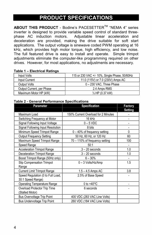
PRODUCT SPECIFICATIONS ABOUT THIS PRODUCT - Bodine’s PACESETTERTM “NEMA 4” series inverter is designed to provide variable speed control of standard three-phase AC induction motors. Adjustable linear acceleration and deceleration are provided, making the drive suitable for soft start applications. The output voltage is sinewave coded PWM operating at 16 kHz, which provides high motor torque, high efficiency, and low noise. The full featured drive is easy to install and operate. Simple trimpot adjustments eliminate the computer-like programming required on other drives. However, for most applications, no adjustments are necessary.
Table 1 – Electrical Ratings
Input Volts 115 or 230 VAC +/- 10%, Single Phase, 50/60Hz Input Current 11.0 (115V) or 7.0 (230V) Amps AC Output Volts 0 – 230 VAC, Three Phase Output Current, per Phase 2.4 Amps RMS Maximum Motor HP (kW) ½ HP (0.37 kW)
Table 2 - General Performance Specifications
Parameter
Specification
Factory Setting
Maximum Load 150% Current Overload for 2 Minutes - Switching Frequency at Motor 16 kHz - Signal Following Input Voltage 0 – 5 VDC - Signal Following Input Resolution 8 bits - Minimum Speed Trimpot Range 0 – 40% of frequency setting 0 Output Frequency Setting 50 Hz, 60 Hz, or 120 Hz 60 Maximum Speed Trimpot Range 70 – 110% of frequency setting 100 Speed Range 50:1 - Acceleration Trimpot Range .3 – 20 seconds 1.0 Deceleration Trimpot Range .3 – 20 seconds 1.0 Boost Trimpot Range (50Hz only) 6 – 30% - Slip Compensation Trimpot Range
0 – 3 Volts/Hz/Amp 1.5
Current Limit Trimpot Range 1.5 – 4.5 Amps AC 3.8 Speed Regulation (0 to Full Load, 30:1 Speed Range)
2.5% of Base Speed -
Operating Temperature Range 0 to +40OC - Overload Protector Trip Time (Stalled Motor)
6 seconds -
Bus Overvoltage Trip Point 400 VDC (283 VAC Line Volts) Bus Undervoltage Trip Point 260 VDC (184 VAC Line Volts)

5
IMPORTANT SAFETY PRECAUTIONS Model 2995 has been evaluated by Underwriters Laboratories for conformance to UL standards 508 and 50 and CSA standard C22.2 No. 14 and bears the UL Recognized Component mark. The AC Drive is a power electronic device. For safety reasons, please read through this operations manual in detail and observe those paragraphs with the safety alert symbol.
This is the safety alert symbol. It is used to alert you to potential personal injury hazards. Obey all safety messages that follow this symbol to avoid possible injury or death.
WARNING WARNING indicates a potentially hazardous
situation which, if not avoided, could result in death or serious injury.
CAUTION CAUTION indicates a potentially hazardous
situation which, if not avoided, may result in minor or moderate injury.
CAUTION CAUTION used without the safety alert symbol indicates a potentially hazardous situation which, if not avoided, may result in property damage.
WARNING Do not touch printed circuit board (PCB) right after
turning off power. Wait until power light turns off. Do not attempt to wire circuitry while power is on. Do not attempt to examine components and signals on
the PCB while the inverter is operating. Do not attempt to disassemble or modify internal
circuitry, wiring, or components of the inverter. Inverter must be properly grounded.
6
INSTALLATION
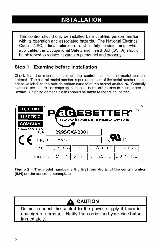
This control should only be installed by a qualified person familiar with its operation and associated hazards. The National Electrical Code (NEC), local electrical and safety codes, and when applicable, the Occupational Safety and Health Act (OSHA) should be observed to reduce hazards to personnel and property.
Step 1. Examine before installation Check that the model number on the control matches the model number ordered. The control model number is printed as part of the serial number on an adhesive label on the outside bottom surface of the control enclosure. Carefully examine the control for shipping damage. Parts errors should be reported to Bodine. Shipping damage claims should be made to the freight carrier.
Figure 2 – The model number is the first four digits of the serial number (S/N) on the control’s nameplate.
CAUTION Do not connect the control to the power supply if there is any sign of damage. Notify the carrier and your distributor immediately.

7
Step 2. Choose a Suitable Location The installation site directly impacts the functionality and lifespan of the control. Avoid areas where surrounding air temperature exceeds 40OC (direct
sunlight or near heating equipment or inside a panel without a cooling fan. Avoid locations where the front panel dial and switch may be bumped and
accidentally turned on/off or damaged. Avoid environments with corrosive gas. Avoid locations near radioactive matter or flammable material. Avoid locations near equipment that generate electromagnetic interference
(soldering or power machinery). Avoid mounting the control to a surface that vibrates.
Step 3 – Mount the Control
Prepare the mounting surface by drilling four holes with their centers located as shown in Figure 3. If #10 screws are to be used for mounting, then use a #6 (.204) clearance drill. If #10-32 machine screws are to be used for mounting, then use a #20 (.161) tap drill. After the mounting surface has been prepared, mount the control with screws through the four mounting brackets (already attached to back of control enclosure).
Figure 3 - Mounting
Dimensions

8
CONNECTION
CAUTION The PCB inside the inverter enclosure is vulnerable to
static electrical charges. Avoid contact with the PCB. Choose an appropriate power source with correct
voltage settings for the specification of the AC inverter. Do not use a separate device between control and
motor to switch motor ON or OFF during operation. Step 4 – Preliminary Setup
Figure 4 - Inside of control, showing location of jumpers and fuses.
BASE FREQUENCY JUMPER - Model 2995 is factory set to operate 60 Hz and 50/60 Hz motors. For 50 Hz motors, remove jumper J1 on the lower printed circuit board. When the control is set for 50 Hz operation, the DECEL/B trimpot will automatically change to adjustable boost. The control can also operate 60 Hz and 50/60 Hz motors (not 50 Hz motors) in an over speed mode by moving the jumposition. - The different ways of
e base frequency jumper.
per to the 120 Hz Figure 5 setting th
9
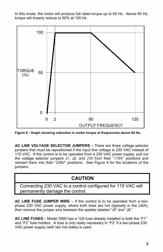
In this mode, the motor will produce full rated torque up to 60 Hz. Above 60 Hz, torque will linearly reduce to 50% at 120 Hz.
Figure 6 - Graph showing reduction in motor torque at frequencies above 60 Hz. AC LINE VOLTAGE SELECTOR JUMPERS – There are three voltage selector jumpers that must be repositioned if the input line voltage is 230 VAC instead of 115 VAC. If the control is to be operated from a 230 VAC power supply, pull out the voltage selector jumpers J1, J2, and J10 from their “115V” positions and reinsert them into their “230V” positions. See Figure 4 for the locations of the jumpers.
CAUTION Connecting 230 VAC to a control configured for 115 VAC will permanently damage the control.
AC LINE FUSE JUMPER WIRE – If the control is to be operated from a two-phase 230 VAC power supply, where both lines are hot (typically in the USA), then remove the jumper wire between the spades labeled “J5” and “J8.” AC LINE FUSES – Model 2995 has a 12A fuse already installed in both the “F1” and “F2” fuse holders. A fuse is only really necessary in “F2” if a two-phase 230 VAC power supply (with two hot sides) is used.

10
Step 5 – Connect the Motor A cord should be used for the motor connection in order to properly seal the liquid tight fitting. The fitting will accept cord diameters between 0.17” and 0.47” diameter. The length of the cord should be kept short for minimum voltage drop and only copper wire with 60O C rated insulation should be used. Loosen the nut from the liquid tight fitting and insert the cord through the fitting and into the enclosure. Connect the three motor power leads to “U”, “V”, and “W” on the terminal block inside the control. Since the controls are capable of changing motor direction electronically, it doesn’t really matter which motor wires go to which terminal. However, if it is desired for the motor to rotate a specific direction when wired a certain way, then refer to the connection diagrams for Bodine inverter-duty motors in Figures 8 and 9 on the next page. If the motor doesn’t rotate in the desired direction as connected, with reference to the “forward” and “reverse” settings of the direction switch on Model 2995, then swap any two of the three motor wires. Note that these connection diagrams apply to Bodine motors only. The terminal block will accept wire sizes from 18 to 14 gauge. The terminal block screws should be tightened to 6 lb-in (0.678 Nm). Connect the motor frame ground to “CHASSIS GROUND” on the terminal block. When the connections are done, tighten the nut on the liquid tight fitting.
Figure 7 - Electrical connections for Model 2995.
11
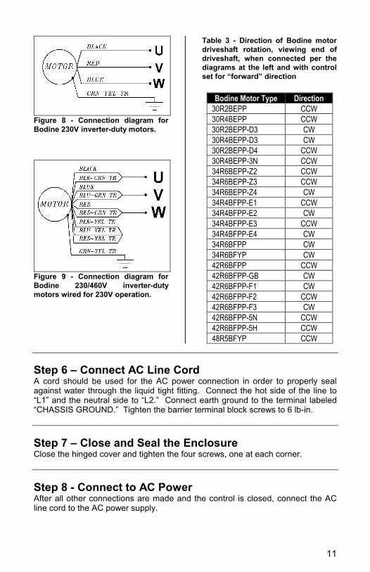
Figure 8 - Connection diagram for Bodine 230V inverter-duty motors.
Figure 9 - Connection diagram for Bodine 230/460V inverter-duty motors wired for 230V operation.
Table 3 - Direction of Bodine motor driveshaft rotation, viewing end of driveshaft, when connected per the diagrams at the left and with control set for “forward” direction
Bodine Motor Type Direction 30R2BEPP CCW 30R4BEPP CCW 30R2BEPP-D3 CW 30R4BEPP-D3 CW 30R2BEPP-D4 CCW 30R4BEPP-3N CCW 34R6BEPP-Z2 CCW 34R6BEPP-Z3 CCW 34R6BEPP-Z4 CW 34R4BFPP-E1 CCW 34R4BFPP-E2 CW 34R4BFPP-E3 CCW 34R4BFPP-E4 CW 34R6BFPP CW 34R6BFYP CW 42R6BFPP CCW 42R6BFPP-GB CW 42R6BFPP-F1 CW 42R6BFPP-F2 CCW 42R6BFPP-F3 CW 42R6BFPP-5N CCW 42R6BFPP-5H CCW 48R5BFYP CCW
Step 6 – Connect AC Line Cord A cord should be used for the AC power connection in order to properly seal against water through the liquid tight fitting. Connect the hot side of the line to “L1” and the neutral side to “L2.” Connect earth ground to the terminal labeled “CHASSIS GROUND.” Tighten the barrier terminal block screws to 6 lb-in. Step 7 – Close and Seal the Enclosure Close the hinged cover and tighten the four screws, one at each corner. Step 8 - Connect to AC Power After all other connections are made and the control is closed, connect the AC line cord to the AC power supply.

12
OPERATION Step 9 – Check System Before Starting
WARNING Recheck all connections. Do not open the cover of the inverter when the power is
ON to avoid injury caused by electrical shock. Do not attempt to wire circuitry while power is on.
CAUTION Do not attempt to make or break connections between
motor and inverter when the power supply is turned on, or the inverter may be damaged due to a surge peak.
Check that motor is securely mounted. Test motor unloaded first to verify proper setup. Check all rotating members. Be sure keys, pulleys, etc.
are securely fastened and safety guards are in place. Check for proper mounting and alignment of products,
and verify safe loading on shafts and gears. The inverter can be easily operated from a low speed to
a high speed. Reconfirm the operating speed range of the motor and the machinery you are controlling.
FIGURE 10 – Control panel layout
13
Step 10 – Operate the Inverter The PACESETTERTM “NEMA 4” series inverter is operated using the switches and speed dial on the front panel of the control. See Figure 10 for panel layout. 1) Turn the AC power ON using the toggle switch. The power lamp will
illuminate. 2) Turn the direction switch to either the “forward” or “reverse” position. 3) Adjust speed by turning the knob of the speed potentiometer. Turning the
pot fully CCW will produce the minimum output frequency, as set by the MIN trim pot inside the control (factory setting is 0 Hz). Turning the pot fully CW will produce the maximum output frequency, as set by the max speed jumper and the MAX trim pot inside the control (factory setting is 60 Hz).
4) To stop the motor momentarily, turn the direction switch to the “stop” position.
5) To change direction of the motor, turn the direction switch to the “stop” position, wait until the motor comes to a complete stop, and then turn the direction switch to either “forward” or “reverse” position.
6) To stop the motor for long periods of time, turn the AC power off using the toggle switch.
7) If the motor does not start promptly and run smoothly, refer to the “TROUBLESHOOTING” section.
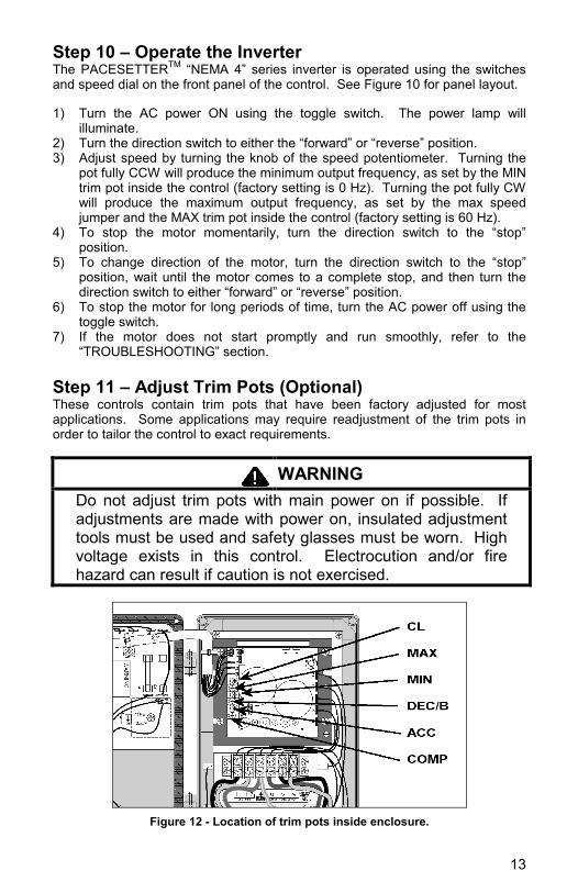
Step 11 – Adjust Trim Pots (Optional) These controls contain trim pots that have been factory adjusted for most applications. Some applications may require readjustment of the trim pots in order to tailor the control to exact requirements.
WARNING Do not adjust trim pots with main power on if possible. If adjustments are made with power on, insulated adjustment tools must be used and safety glasses must be worn. High voltage exists in this control. Electrocution and/or fire hazard can result if caution is not exercised.
Figure 12 - Location of trim pots inside enclosure.
14
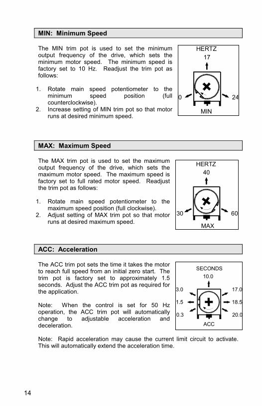
MIN: Minimum Speed The MIN trim pot is used to set the minimum output frequency of the drive, which sets the minimum motor speed. The minimum speed is factory set to 10 Hz. Readjust the trim pot as follows:
1. Rotate main speed potentiometer to the
minimum speed position (full counterclockwise).
2. Increase setting of MIN trim pot so that motor runs at desired minimum speed.
MAX: Maximum Speed The MAX trim pot is used to set the maximum output frequency of the drive, which sets the maximum motor speed. The maximum speed is factory set to full rated motor speed. Readjust the trim pot as follows:
1. Rotate main speed potentiometer to the
maximum speed position (full clockwise). 2. Adjust setting of MAX trim pot so that motor
runs at desired maximum speed.
ACC: Acceleration The ACC trim pot sets the time it takes the motor to reach full speed from an initial zero start. The trim pot is factory set to approximately 1.5 seconds. Adjust the ACC trim pot as required for the application. Note: When the control is set for 50 Hz operation, the ACC trim pot will automatically change to adjustable acceleration and deceleration. Note: Rapid acceleration may cause the current limit circuit to activate. This will automatically extend the acceleration time.
MIN
17HERTZ
240
MAX
40HERTZ
6030
ACC
10.0
18.51.5
SECONDS
3.0 17.0
0.3 20.0

15
DEC/B: Deceleration (with 60 Hz or 120 Hz configuration) The DEC/B trim pot sets the time it will take the motor to reach zero speed from an initial full speed setting. The trim pot is factory set to approximately 1.5 seconds. Adjust the trim pot as required for the application. Application Note: On applications with high inertial loads, the deceleration may automatically increase in time. This will slow down the rate of speed decrease to prevent the DC bus voltage from rising to the overvoltage trip point. This function is called regeneration protection. It is recommended that for very high inertial loads that both the ACC and DEC/B trim pots be set to a minimum of 10 seconds. DEC/B: Boost (with 50 Hz configuration) When the control is set for 50 Hz motors, the DEC/B trim pot becomes Adjustable Boost. Most 60 Hz motors conforming to NEMA standards can operate from a preset volts/Hz curve. 50 Hz motors generally differ widely in their characteristics. Therefore, it is necessary to have Adjustable Boost to obtain maximum motor performance. Since the boost trim pot was the deceleration trim pot in the 60 Hz mode, it will take on the prior setting of the DEC/B trim pot. In order for the 50 Hz motor to run properly, the boost must be adjusted. If the application does not require full torque below 10 Hz, the boost trim pot can be conservatively set at 8% (9 o’clock position). If more precise speed regulation is required due to varying load, the boost can be set as follows. 1. Place an AC analog RMS ammeter in series with one motor lead
(Generally, digital or clamp-on meters do not yield accurate readings). 2. Run the motor unloaded* at approximately 4 Hz (or 120 RPM). (*Note:
An unloaded motor with excessive boost will draw more current than a partially loaded motor.)
3. Turn up boost until the ammeter reaches the nameplate rating. 4. Using the main speed potentiometer, slowly adjust motor speed over a
0 – 15 Hz (0 – 450 RPM) range. If motor current exceeds nameplate rating, lower boost setting.
CAUTION To avoid motor winding overheating and failure, do not over boost motor.
DEC
10.0
SECONDS
18.51.5
(60Hz ONLY)
20.00.3
17.03.0
DEC/B
18
50 Hz% BOOST
26
306
10
16
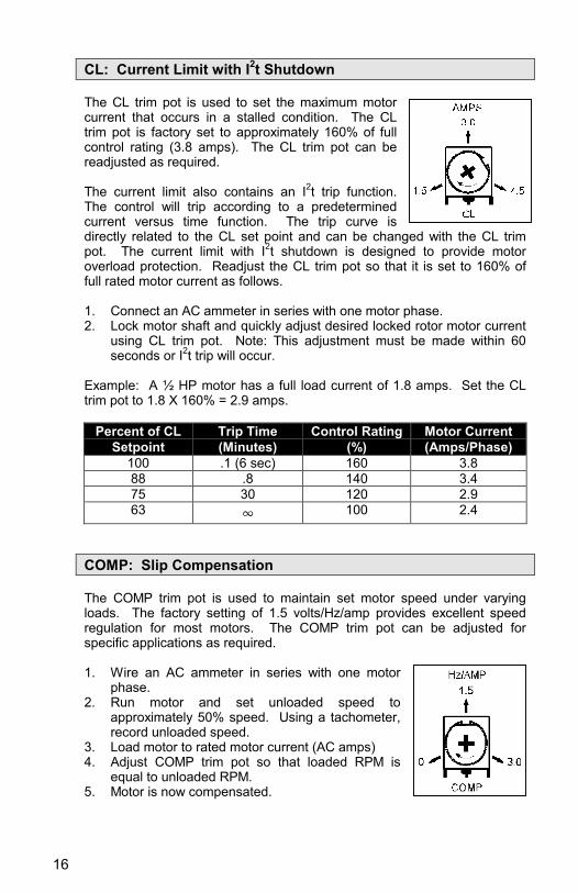
CL: Current Limit with I2t Shutdown The CL trim pot is used to set the maximum motor current that occurs in a stalled condition. The CL trim pot is factory set to approximately 160% of full control rating (3.8 amps). The CL trim pot can be readjusted as required. The current limit also contains an I2t trip function. The control will trip according to a predetermined current versus time function. The trip curve is directly related to the CL set point and can be changed with the CL trim pot. The current limit with I2t shutdown is designed to provide motor overload protection. Readjust the CL trim pot so that it is set to 160% of full rated motor current as follows. 1. Connect an AC ammeter in series with one motor phase. 2. Lock motor shaft and quickly adjust desired locked rotor motor current
using CL trim pot. Note: This adjustment must be made within 60 seconds or I2t trip will occur.
Example: A ½ HP motor has a full load current of 1.8 amps. Set the CL trim pot to 1.8 X 160% = 2.9 amps.
Percent of CL Setpoint
Trip Time (Minutes)
Control Rating (%)
Motor Current (Amps/Phase)
100 .1 (6 sec) 160 3.8 88 .8 140 3.4 75 30 120 2.9 63 4 100 2.4
COMP: Slip Compensation The COMP trim pot is used to maintain set motor speed under varying loads. The factory setting of 1.5 volts/Hz/amp provides excellent speed regulation for most motors. The COMP trim pot can be adjusted for specific applications as required. 1. Wire an AC ammeter in series with one motor
phase. 2. Run motor and set unloaded speed to
approximately 50% speed. Using a tachometer, record unloaded speed.
3. Load motor to rated motor current (AC amps) 4. Adjust COMP trim pot so that loaded RPM is
equal to unloaded RPM. 5. Motor is now compensated.

17
TROUBLESHOOTING
WARNING Do not remove the cover of the inverter when the power
is ON to avoid injury caused by electrical shock. This control does not require maintenance under normal conditions. If you encounter a problem, read all instructions provided with this control and double-check the wiring. If problems persist, contact your source of purchase or a Bodine Authorized Service Center and describe the problem in detail. Performing unauthorized repairs will void the Warranty. GENERAL EVALUATION – Knowing the circumstances under which the problem occurred can help to identify the root cause of the problem. Has the system ever operated properly? If the control was just installed and doesn’t work right, then it is likely that something wasn’t done correctly in the installation. However, if the system has been working for an extended period of time and just recently stopped working, then this would indicate that the control was initially installed properly but something has somehow changed. Is the problem continuous or intermittent? If the problem always occurs and never goes away, then it would indicate something inherently wrong in the connections or a defective component. On the other hand, if the system operates properly most of the time and only occasionally does something wrong, then this might indicate loose connections or electrical noise interference. Table 4 - General problem evaluation method
ABNORMALITY CHECK POINT COUNTERMEASURE Is main power lamp illuminated? Check that power source is switched on.
Reconfirm the power voltage level. Is a problem indicated by the LED status indicator?
See Table 5 for interpretation.
Motor does not run
Is there a direction command? Check that the direction switch is set at either Forward or Reverse.
Is the main speed pot damaged? Examine the speed pot and correct it. Motor runs, but in
wrong direction Is wiring to the motor correct? Swap any two of the three motor wires.
Change direction jumper (Model 2997) Change direction switch (Model 2996)
Is the main speed pot damaged? Examine the speed pot and correct it. Motor runs, but speed can’t be adjusted Is the loading too heavy? Reduce loading
Is motor specification correct? Reconfirm motor specification. Is the gear ratio correct? Reconfirm gear ratio
Motor runs, but speed is too high
or too low Is the MAX trim pot setting correct? Check MAX trim pot setting. Is the loading too heavy? Increase inverter and motor capacity Is the loading variation too large? Reduce loading variation
Motor runs, but with abnormal speed
variations Is input power steady and stable? Install AC reactor on power supply input.
18
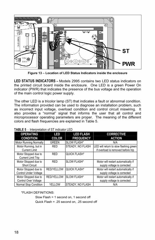
Figure 13 – Location of LED Status Indicators inside the enclosure
LED STATUS INDICATORS – Models 2995 contains two LED status indicators on the printed circuit board inside the enclosure. One LED is a green Power On indicator (PWR) that indicates the presence of the bus voltage and the operation of the main control logic power supply. The other LED is a tricolor lamp (ST) that indicates a fault or abnormal condition. The information provided can be used to diagnose an installation problem, such as incorrect input voltage, overload condition and control circuit miswiring. It also provides a “normal” signal that informs the user that all control and microprocessor operating parameters are proper. The meaning of the different colors and flash frequencies are explained in Table 5. TABLE 5 – Interpretation of ST indicator LED
OPERATING CONDITION
LED COLOR
LED FLASH FREQUENCY
CORRECTIVE ACTION
Motor Running Normally GREEN SLOW FLASH* N/A Motor Running, but in
Current Limit RED STEADY, NO FLASH LED will return to slow flashing green
if overload is removed before trip Motor Stopped due to
Current Limit Trip RED QUICK FLASH*
Motor Stopped due to Short Circuit
RED SLOW FLASH* Motor will restart automatically if supply voltage is corrected
Motor Stopped due to Control Under Voltage
RED/YELLOW QUICK FLASH* Motor will restart automatically if supply voltage is corrected
Motor Stopped due to Control Over Voltage
RED/YELLOW SLOW FLASH* Motor will restart automatically if supply voltage is corrected
Normal Stop Condition YELLOW STEADY, NO FLASH N/A
*FLASH DEFINITIONS: • Slow Flash = 1 second on, 1 second off • Quick Flash = .25 second on, .25 second off

19
DECLARATION OF CONFORMITY We, the Bodine Electric Company, 2500 W. Bradley Place, Chicago, Illinois, U.S.A., phone (773) 478-3515, fax (773) 478-3232, declare under our sole responsibility that the following products:
Type HPP-5337E4 AC Motor Speed Control, Model number 2995
Are in conformity with the following standards when installed in accordance with the supplied installation instructions:
EN61010-1 Safety Requirements for Electrical Equipment EN61800-3 Adjustable Speed Electrical Power Drive Systems EMC
Product Standard
EN50081 Electromagnetic Compatibility - General Emissions Standard
EN50082 Elecromagnetic Compatibility - Generic Immunity Standard EN55011 Radiated and Conducted Emissions EN61000 Electromagnetic Compatibility – Low Voltage Supply
Fluctuations and Harmonics And therefore satisfies the conditions for the following EC directives:
Low Voltage Directive
EMC Directive 89/336/EEC making the products eligible for the CE Mark. The undersigned hereby declares that the products specified above conform to the above standards:
Signature: Full Name: Terrence J. Auchstetter Position: Product Manager Date: August 2, 2002

20
BODINE LIMITED WARRANTY The Bodine Electric Company warrants all products it manufactures to be free of defects in workmanship and materials when used under Normal Operating Conditions and when applied in accordance with nameplate specifications. When Bodine motors and gearmotors have been purchased with and used only with appropriately applied Bodine controls, this warranty shall be in effect for a period of twenty-four months from date of purchase or thirty months from date of manufacture, whichever comes first. Bodine motors and gearmotors used with non-Bodine controls and Bodine controls used with non-Bodine motors and gearmotors are covered by the standard twelve-month warranty period. The Bodine Electric Company will repair or replace at its option, any of its products which has been found to be defective and is within the warranty period, provided that the product is shipped freight prepaid, with previous authorization, to Bodine’s plant in Chicago, Illinois 60618 U.S.A., or to the nearest Bodine Authorized Service Center. At its option, all return shipments are F.O.B. Bodine’s plant or Authorized Service Center. Bodine is not responsible for removal, installation, or any other incidental expenses incurred in shipping the products to or from Bodine. This warranty is in lieu of any other expressed or implied warranty - including (but not limited to) any implied warranties of merchantability and/or fitness for a particular use or purpose. Bodine’s liability under this warranty shall be solely limited to repair or replacement of the Bodine product within the warranty period and Bodine shall not be liable, under any circumstances, for any consequential, incidental or indirect damages or expenses associated with the warranted products. Commutator and/or brush wear and its associated effects are normal occurrences and are not covered by this warranty. Any Bodine product that is damaged due to misuse, abuse, negligence or has been modified or dismantled without the knowledge or written consent of Bodine, is not covered by this warranty. Proof of purchase of motor or gearmotor and matching control as a system must be provided with any claim.
Bodine Electric Company 2500 W. Bradley Place Chicago, Illinois 60618 U.S.A. TEL: (773) 478-3515 FAX: (773) 478-3232 www.bodine-electric.com
P/N 074 01040 B (DX)