Embed Size (px)
Citation preview
3-Phase BLDC Motor Control onKinetis
User’s Guide
Document Number:BLDCK60UGRev. 0
09/2011

How to Reach Us:
Home Page:www.freescale.com
E-mail:[email protected]
USA/Europe or Locations Not Listed:Freescale SemiconductorTechnical Information Center, CH3701300 N. Alma School RoadChandler, Arizona 85224+1-800-521-6274 or [email protected]
Europe, Middle East, and Africa:Freescale Halbleiter Deutschland GmbHTechnical Information CenterSchatzbogen 781829 Muenchen, Germany+44 1296 380 456 (English)+46 8 52200080 (English)+49 89 92103 559 (German)+33 1 69 35 48 48 (French)[email protected]
Japan:Freescale Semiconductor Japan Ltd.HeadquartersARCO Tower 15F1-8-1, Shimo-Meguro, Meguro-ku,Tokyo 153-0064, Japan0120 191014 or +81 3 5437 [email protected]
Asia/Pacific:Freescale Semiconductor China Ltd.Exchange Building 23FNo. 118 Jianguo RoadChaoyang DistrictBeijing 100022China +86 10 5879 8000 [email protected]
For Literature Requests Only:Freescale Semiconductor Literature Distribution CenterP.O. Box 5405Denver, Colorado 802171-800-441-2447 or 303-675-2140Fax: [email protected]
Information in this document is provided solely to enable system and software implementers to use Freescale Semiconductor products. There are no express or implied copyright licenses granted hereunder to design or fabricate any integrated circuits or integrated circuits based on the information in this document.
Freescale Semiconductor reserves the right to make changes without further notice to any products herein. Freescale Semiconductor makes no warranty, representation or guarantee regarding the suitability of its products for any particular purpose, nor does Freescale Semiconductor assume any liability arising out of the application or use of any product or circuit, and specifically disclaims any and all liability, including without limitation consequential or incidental damages. “Typical” parameters that may be provided in Freescale Semiconductor data sheets and/or specifications can and do vary in different applications and actual performance may vary over time. All operating parameters, including “Typicals”, must be validated for each customer application by customer’s technical experts. Freescale Semiconductor does not convey any license under its patent rights nor the rights of others. Freescale Semiconductor products are not designed, intended, or authorized for use as components in systems intended for surgical implant into the body, or other applications intended to support or sustain life, or for any other application in which the failure of the Freescale Semiconductor product could create a situation where personal injury or death may occur. Should Buyer purchase or use Freescale Semiconductor products for any such unintended or unauthorized application, Buyer shall indemnify and hold Freescale Semiconductor and its officers, employees, subsidiaries, affiliates, and distributors harmless against all claims, costs, damages, and expenses, and reasonable attorney fees arising out of, directly or indirectly, any claim of personal injury or death associated with such unintended or unauthorized use, even if such claim alleges that Freescale Semiconductor was negligent regarding the design or manufacture of the part.
Freescale™ and the Freescale logo are trademarks of Freescale Semiconductor, Inc. All other product or service names are the property of their respective owners.
© 1994-2008 ARC™ International. All rights reserved.
© Freescale Semiconductor, Inc. 2011. All rights reserved.
Document Number: BLDCK60UGRev. 009/2011

3-Phase BLDC Motor Control on Kinetis, Rev. 0
i Freescale Semiconductor
Chapter 1Introduction
1.1 About this Manual . . . . . . . . . . . . . . . . . . . . . . . . . . . . . . . . . . . . . . . . . . . . . . . . . 21.2 Warnings . . . . . . . . . . . . . . . . . . . . . . . . . . . . . . . . . . . . . . . . . . . . . . . . . . . . . . . . 31.3 Set-up Guide . . . . . . . . . . . . . . . . . . . . . . . . . . . . . . . . . . . . . . . . . . . . . . . . . . . . . 41.4 USB-to-Serial Cable Driver Installation . . . . . . . . . . . . . . . . . . . . . . . . . . . . . . . . . 71.5 FreeMASTER Software Installation . . . . . . . . . . . . . . . . . . . . . . . . . . . . . . . . . . . . 81.6 FreeMASTER Control . . . . . . . . . . . . . . . . . . . . . . . . . . . . . . . . . . . . . . . . . . . . . . 81.7 Ethernet Set-up . . . . . . . . . . . . . . . . . . . . . . . . . . . . . . . . . . . . . . . . . . . . . . . . . . . 91.8 Web Control . . . . . . . . . . . . . . . . . . . . . . . . . . . . . . . . . . . . . . . . . . . . . . . . . . . . . 111.9 Integration of the Motor Control Driver into Other Applications . . . . . . . . . . . . . . 12

3-Phase BLDC Motor Control on Kinetis, Rev. 0
Freescale Semiconductor 1-2
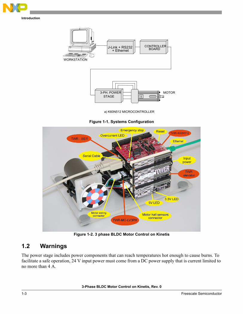
Chapter 1 IntroductionThis application demonstrates a low power 3-phase (Brushless DC) BLDC motor drive software. It is focused on a simple and easy to understand control approach of BLDC and using MQX in a time critical application. The control concept of the application is a speed closed-loop BLDC drive using a Hall position sensor. It serves as an example of a BLDC motor control system for low voltage motor applications. The power stage is designed for an input voltage +24V DC. The hardware is built on the Freescale Tower rapid prototyping system and contains the following modules:
• TWR elevator
• TWR K60N512
• TWR Low Voltage Power Stage
• TWR Serial Board
There are two versions of the application software:
• BLDC under the MQX RTOS and web server
• BLDC on bare metal
Both use the same source code for motor control. The MQX version contains a web server to demonstrate benefits of the MQX-based solution. Both applications can be also controlled by FreeMASTER software. This FreeMASTER PC application allows real-time monitoring or modification of all required variables through an easy and user-friendly graphical user interface. Selected variables can also be monitored in a time domain scope representation. The MQX version can be controlled from any web browser on a PC via the Ethernet communication interface, because in this version the web server is implemented.
1.1 About this Manual
Following sections of this manual provides the key items:
• Introduction of the demo Chapter 1, “Introduction
• Information about safety in using the demo Section 1.2, “Warnings
• Set-up instructions are found in Section 1.3, “Set-up Guide
• USB to serial installation Section 1.4, “USB-to-Serial Cable Driver Installation
• FreeMASTER installation Section 1.5, “FreeMASTER Software Installation
• Control via FreeMaster Section 1.6, “FreeMASTER Control
• Ethernet controller set-up Section 1.7, “Ethernet Set-up
• Control of the application via ethernet Section 1.8, “Web Control
• Control from other application Section 1.9, “Integration of the Motor Control Driver into Other Applications
Introduction
3-Phase BLDC Motor Control on Kinetis, Rev. 0
1-3 Freescale Semiconductor
Figure 1-1. Systems Configuration
Figure 1-2. 3 phase BLDC Motor Control on Kinetis
1.2 Warnings
The power stage includes power components that can reach temperatures hot enough to cause burns. To facilitate a safe operation, 24 V input power must come from a DC power supply that is current limited to no more than 4 A.
CONTROLLERBOARD
3-PH. POWERSTAGE
MOTOR
WORKSTATION
J-Link + RS232
a) K60N512 MICROCONTROLLER
+ Ethernet

Introduction
3-Phase BLDC Motor Control on Kinetis, Rev. 0
Freescale Semiconductor 1-4
The user must be aware of the following:
• Before moving scope probes, making connections and so on, it is generally advisable to power down the 24 V supply.
• Wearing safety glasses, avoiding ties and jewelry, using shields, and operation by personnel trained in power electronics lab techniques are also advisable.
• Do not plug any other cables into the demo system except for the power supply cable, ethernet cable and serial communication cable. The demo can be powered only via the Tower Low Voltage Power Stage power jack.
• Do not connect any USB cable to the demo while the power is applied to the power stage module.
• Connecting a USB cable to the Tower Elevator Module will cause damage to the Kinetis K60 MCU and other systems.
• Only a J-Link can be used for firmware upload.
1.3 Set-up Guide
Follow these steps to set up the board:
1. Jumper settings (board TWR-K60N512 REV C) see Figure 1-3.
The jumpers must be already configured. If not, configure it as described below.
For standalone operation:
• TWR-K60N512 - Jumper J6 to position 1-2
• To enable ethernet communication (use with TWR-SER):
• TWR-K60N512 - Jumper J6 to position 2-3 - processor clock taken from the TWR-SER board
• TWR-SER - CLK_SEL 3-4
• TWR-SER - CLKIN-SEL 2-3 (processor clock is taken from the PHY)
• TWR-SER - ETH-CONFIG J12 9-10 to select the RMII communication mode
NOTE
Both the processor and serial board (TWR-SER) have to be plugged into the Tower. The Processor is using an external clock from the Ethernet PHY on the serial card.
• All jumpers and other hardware switches not specifically described are expected to be in factory-default positions. Please refer to the "TWR-K60N512 User's Manual" and "Tower System Serial Module - User Manual" available from www.freescale.com for the default settings.
Introduction
3-Phase BLDC Motor Control on Kinetis, Rev. 0
1-5 Freescale Semiconductor
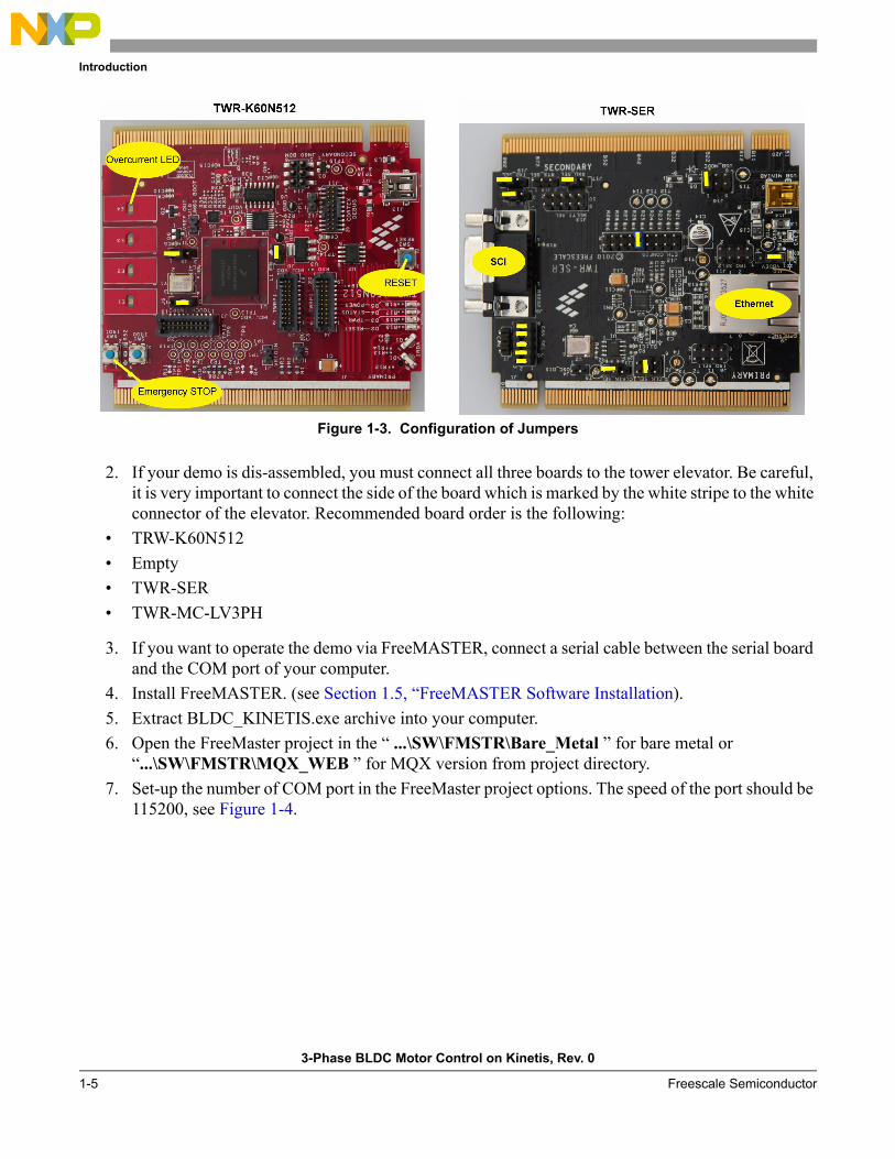
Figure 1-3. Configuration of Jumpers
2. If your demo is dis-assembled, you must connect all three boards to the tower elevator. Be careful, it is very important to connect the side of the board which is marked by the white stripe to the white connector of the elevator. Recommended board order is the following:
• TRW-K60N512
• Empty
• TWR-SER
• TWR-MC-LV3PH
3. If you want to operate the demo via FreeMASTER, connect a serial cable between the serial board and the COM port of your computer.
4. Install FreeMASTER. (see Section 1.5, “FreeMASTER Software Installation).
5. Extract BLDC_KINETIS.exe archive into your computer.
6. Open the FreeMaster project in the “ ...\SW\FMSTR\Bare_Metal ” for bare metal or “...\SW\FMSTR\MQX_WEB ” for MQX version from project directory.
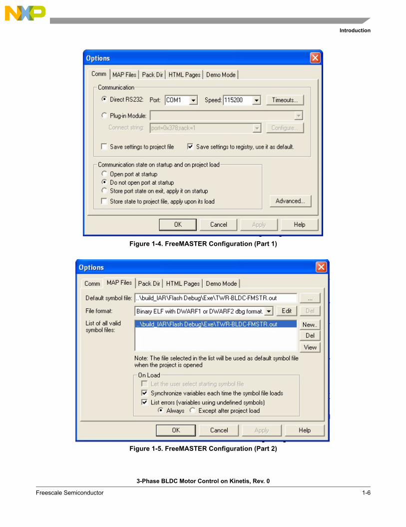
7. Set-up the number of COM port in the FreeMaster project options. The speed of the port should be 115200, see Figure 1-4.
Introduction
3-Phase BLDC Motor Control on Kinetis, Rev. 0
Freescale Semiconductor 1-6
Figure 1-4. FreeMASTER Configuration (Part 1)
Figure 1-5. FreeMASTER Configuration (Part 2)

Introduction
3-Phase BLDC Motor Control on Kinetis, Rev. 0
1-7 Freescale Semiconductor
8. You can also use the USB-to-Serial Cable (USB virtual serial port) that is part of the demo kit, if your notebook or PC has only a USB port. If you use the USB-to-Serial Cable, follow chapter Section 1.4, “USB-to-Serial Cable Driver Installation .
9. If you want to use the demo with MQX, you can skip steps 10,11,12,13,15. Default configuration contains the MQX version already in flash memory, so new firmware loading is not needed.
10. Install the IAR Embedded Workbench.
11. Project directory contains own bsp and psp and library files, already configured as necessary. You do not need to install MQX on your computer.
12. Connect J-Link to TWR-K60N512 board.
13. Open IAR project “...\TWR_BLDC_FMSTR\build_IAR\BLDC_example.eww” for bare metal version, or “...\TWR_MQX_BLDC_FMSTR_WEB\BLDC_WEB_SERVER.eww” for MQX version, from the project directory.
14. Connect a 24 V supply voltage to the power stage, the green LED (D7) near the power supply connector should be lit. If any other voltage is applied, the hardware can be damaged. The power stage generates 3.3 V and 5 V for other modules in the tower system. Presence of 3.3 V is indicated by LED D1 and D7, and the presence of 5 V is indicated by D2 and D6 on the tower elevator.
NOTE
Do not connect any other supply voltage or USB cable.
15. Load firmware via a J-Link and then run application.
16. Never connect the motor connectors to the power stage when you make some firmware changes or hardware changes.
17. Start communication in FreeMaster.
18. Connect both motor connectors to the power stage.
19. Type a speed from 500 to 4000, or -500 to -4000 rpm, into field “speed_req”. The motor should run.
1.4 USB-to-Serial Cable Driver Installation 1. Do not plug the USB-to-Serial Cable into your computer.
2. Insert the CD that is part of the demo kit into your CD-ROM drive.
3. For Windows 2000 /XP/ Server2003, run the following file: [your CD ROM Drive]:\SW\USB to RS232\Windows\Setup.exe
For Windows Vista, run the following file: [your CD ROM Drive]:\SW\USB to RS232\Windows\Vista\Setup.exe
4. Follow the on-screen instructions to complete the installation.
5. Plug the USB-to-Serial adaptor into USB port of the computer.
6. Open “Device Manager” under System Properties and check if the device you installed under “Prolific USB-to-Serial Comm Port (ComXX)” is there. Keep the number of the assigned COM port as it will be needed later during the FreeMASTER software configuration. One possible way to open the System Properties window in Windows XP is as follows:
At the Windows Taskbar click Start and then select \Settings\Control Panel\System. The System Properties window will appear. The “Device Manager” is located at the “Hardware” tab.

Introduction
3-Phase BLDC Motor Control on Kinetis, Rev. 0
Freescale Semiconductor 1-8
7. Now the USB-to-Serial Cable is ready to use.
1.5 FreeMASTER Software Installation
If there is no FreeMASTER software installed on the notebook or PC that you intend to use for the demo control, you can find the installation file in the enclosed CD in the folder \SW\FreeMASTER for PC\FMMASTERSW.exe, or check the most recent version on the Freescale web page:
https://www.freescale.com/webapp/sps/download/license.jsp?colCode=FMASTERSW&appType=file2&location=null&DOWNLOAD_ID=null.
In case of any problem with the installation process or with using of the software, download the documentation from the www.freescale.com.
1.6 FreeMASTER Control
After launching the application and performing all settings described above, click the scope:“BLDC” item in the project tree structure of the FreeMASTER application window, as given in Figure 1-6. In this view, variables used for the application state, speed, PI controller and ramp settings are visible. For the demonstration purposes, this is sufficient.

Introduction
3-Phase BLDC Motor Control on Kinetis, Rev. 0
1-9 Freescale Semiconductor
Figure 1-6. FreeMASTER User Interface
Table 1-1. Variable Description
Variables Description
speed_req Serves in entering the required speed of the motor and the direction of motion. If the number is negative, the motor runs in counter-clockwise direction, and when it is positive the motor runs clockwise. You can modify this variable from -500 to -4000, and from 500 to 4000. Any other numbers will be ignored.
speed_error Shows the difference between the required speed, limited by the ramp motor during acceleration, and the measured speed.
speed_measured Shows the measured speed. Speed under the 500 rpm is not measured exactly.
over_current When the first level of overcurrent is detected, the variable will be set to 1. It can be adjusted by the trimmer on the power stage board.
Introduction
3-Phase BLDC Motor Control on Kinetis, Rev. 0
Freescale Semiconductor 1-10
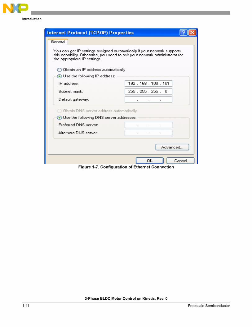
1.7 Ethernet Set-up
To configure the Ethernet communication interface on your PC, follow the given steps:
1. In your local area connection setting window, click on the properties of your internet protocol as given in Figure 1-7
2. Use the manual IP configuration and write:
• IP address: 192.168.100.101
• Subnet mask: 255.255.255.0
3. Click OK.
4. Open Internet Explorer.
5. Go to the Tools \ Internet options.
6. Click the “LAN settings” button.
7. Disable the proxy server, by deselecting the checkbox as given in Figure 1-8.
8. Click OK.
9. Connect the ethernet cable between the Tower Serial Module and your computer.
trMyRamp.s32RampDown
Motor acceleration. Can be set in [ r/s-2 x100] from 1 to 100.
trMyRamp.s32RampUp Motor deceleration. Can be set in [ r/s-2 x100 ] from 1 to 100.
Table 1-1. Variable Description
Variables Description
Introduction
3-Phase BLDC Motor Control on Kinetis, Rev. 0
1-11 Freescale Semiconductor
Figure 1-7. Configuration of Ethernet Connection

Intro
du
ction
3-P
has
e BL
DC
Mo
tor C
on
trol o
n K
inetis, R
ev. 0
Fre
escale Sem
iconductor
1-12
Figure 1-8. Configuration of MS Internet Explorer for Demo Control
1.8 Web Control
The MQX version of the application can be controlled via web server, but you must set-up your ethernet interface. Refer to Section 1.7, “Ethernet Set-up. Then follow the given steps.
1. Open the Internet Explorer

Introduction
3-Phase BLDC Motor Control on Kinetis, Rev. 0
1-13 Freescale Semiconductor
2. Write the IP address of the demo device to the Internet Explorer. The default IP address is 192.168.100.100. And then press enter.
3. You will see a web page with the Freescale logo and title “Freescale MQX™ Web Server” 4. Click the BLDC Control placed on the left side of the web page.
5. You will see the web page as in Section 1.8, “Web Control
6. Click one of the buttons with the required speed.
7. The Motor will be set to motion.
Figure 1-9. Web Page for Speed Control
1.9 Integration of the Motor Control Driver into Other Applications
Both versions of the motor control driver can be part of other applications. The API is defined by the following three functions. A detailed description will be given in AN4376-BLDC Motor Control with Hall Sensors under the MQX on Kinetis.
1. void Set_speed(signed short,int)
First parameter is the input speed in signed short data format. Input value is in RPM.
Second parameter is the number of the motor which receives the command. This demo has only one motor, so enter 1.

Introduction
3-Phase BLDC Motor Control on Kinetis, Rev. 0
Freescale Semiconductor 1-14
Return: Void
2. unsigned char Get_status(void)
Return: Status of the application
0 - IDLE
1 - STOP
2 - RUNNING
3. signed short Get_speed(int)
First parameter is the number of motor which receives the command. This demo has only one motor, so enter 1.
Return: Measured speed in signed short data format. The value is in RPM.
NOTE
The hardware connection between the K60 tower board and the low voltage power stage does not allow to perform a reset of the MOSFET driver by a software command, some faults can be cleared only by pressing the reset button on the K60 tower board. This is the only way the MOSFET driver properly executes the reset procedure.