Embed Size (px)
Citation preview
Power Consumption
With Power Saving Circuit
3 Port Solenoid Valve
CAT.EUS11-86 -UKBbBb
Improved pilot valvePilot valve cover is stronger using stainless steel. Mounting thread is also reinforced from size M1.7 to M2.
�Flow Characteristics
SYJ300SYJ500SYJ700
0.361.22.7
0.310.410.38
0.0890.320.72
Series Flow characteristicsC [dm3/(s·bar)] b Cv
Cover (stainless steel)
92329724
ø[l/min(ANR)]
Series SYJ300/500/700
Series SYJ300/500/700
SYJ300
SYJ500
SYJ700
SYJ300
SYJ500
SYJ700
M3
M5
1/8
M5
1/8
1/8, 1/4
�N.C.�N.O.
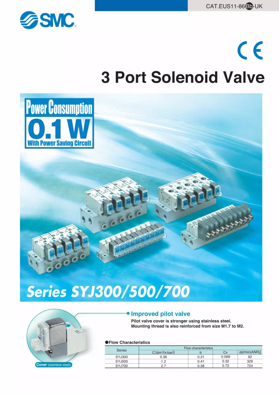
Rubber Seal3 Port Solenoid Valve
Variations
Series Port sizeSonic
conductanceC [dm3/(s·bar)]
Effective area0.9 mm2
2�3(A�R)
0.662�3
(A�R)
2.52�3
(A�R)
1.22�3
(A�R)
2.72�3
(A�R)
Type ofactuation Voltage Electrical entry
Option
With light/surge voltage suppressor
Manualoverride
Note) All AC voltage models have built-in surge voltage suppressor.
� Non- locking push type
� Push-turn locking slotted type
� Push-turn locking lever type
Body
por
ted
Base
mou
nted
For DC
� With surge voltage suppressor� With light/surge voltage suppressor
For DC
� 24 VDC12 VDC
6 VDC5 VDC3 VDC
For AC
For AC
� With light/surge voltage suppressor
� 100 VAC Hz 110 VAC Hz 200 VAC Hz 220 VAC Hz
Note)
Grommet
L plugconnector
M plugconnector
DIN terminal
M8 connector
(SYJ500, 700 only)
0.362�3
(A�R)
–+
–+
–+
Front matter 1
P.1
P.15
P. 33
P. 33
P.1
P.15
5060
5060
5060
5060
For DC
� 24 VDC12 VDC
6 VDC5 VDC3 VDC
For DC
� 24 VAC12 VAC
6 VAC5 VAC3 VAC
For DC
� 24 VDC12 VDC
6 VDC5 VDC3 VDC
For AC
� 100 VAC Hz 110 VAC Hz 200 VAC Hz 220 VAC Hz
5060
5060
5060
5060
Front matter 2
Series SYJ300/500/700
SYJ300
SYJ500
SYJ700
SYJ300
SYJ500
SYJ700
ø8
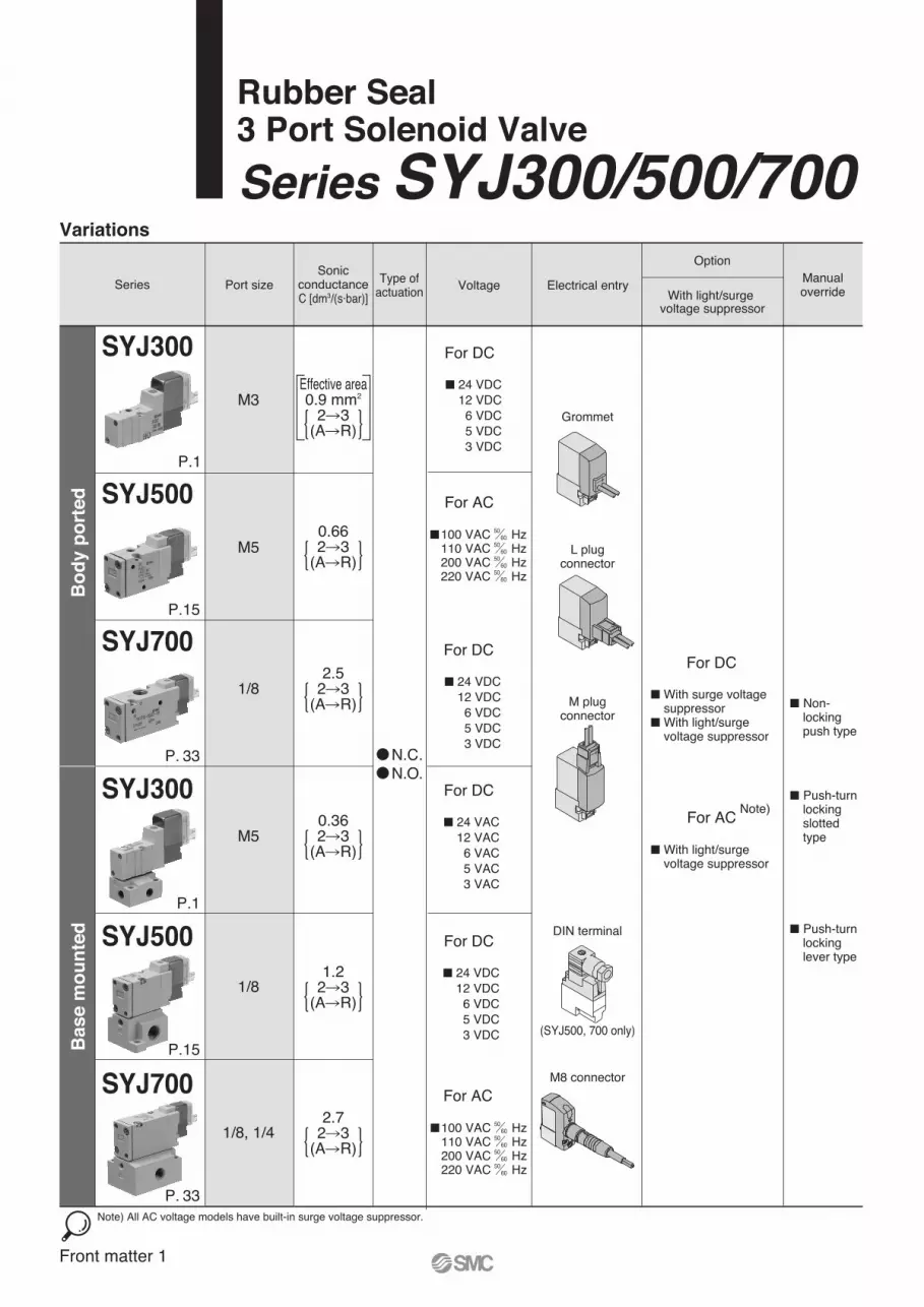
Manifold Variations
Valve series A portlocation
Top
Top
Top
Side
Side
Side
Bottom
Bottom
M5
1/8
1/8
1/8
1/4
M5
1/8
1/8
1/8
1/4
1/4
P, R portssize
A port size
With one-touch fitting
Applicable tubing O.D.
ø6ø4 N3 N7 N9
Note 1) Only for internal pilotNote 2) Only for external pilot
Series SYJ300 Series SYJ500 Series SYJ700
Note 1)
Note 1)
Note 1)
Note 2)
Note 1)
M3 M5 1/8
Bo
dy p
ort
ed
Base m
ou
nte
d
1
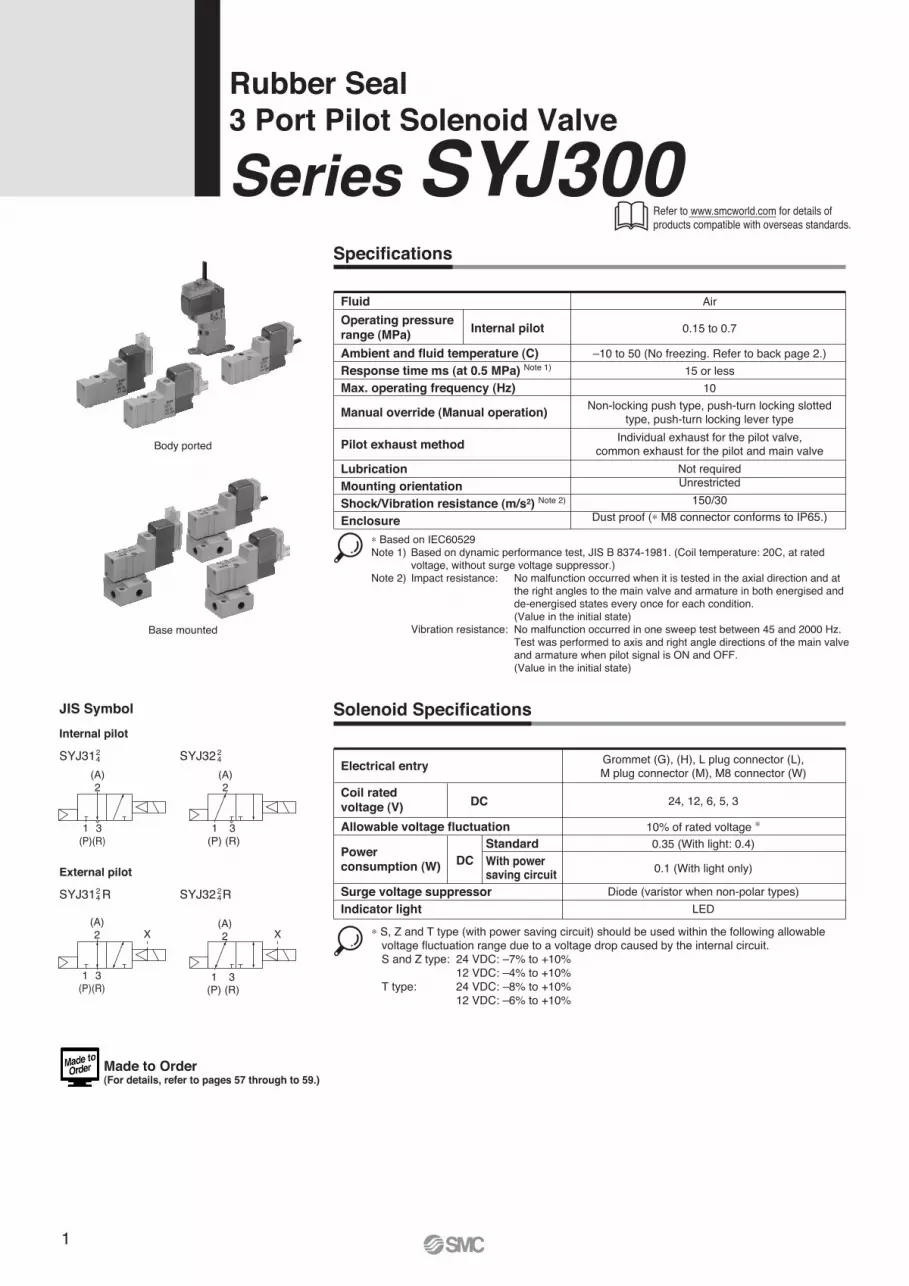
Series SYJ300Rubber Seal3 Port Pilot Solenoid Valve
Specifications
Fluid
Operating pressure range (MPa)
Ambient and fluid temperature (C)Response time ms (at 0.5 MPa) Note 1)
Max. operating frequency (Hz)
Manual override (Manual operation)
Pilot exhaust method
LubricationMounting orientationShock/Vibration resistance (m/s2) Note 2)
Enclosure
Air
0.15 to 0.7Internal pilot
–10 to 50 (No freezing. Refer to back page 2.)15 or less
10Non-locking push type, push-turn locking slotted
type, push-turn locking lever type
Not requiredUnrestricted
150/30Dust proof (∗ M8 connector conforms to IP65.)
Individual exhaust for the pilot valve,common exhaust for the pilot and main valve
∗ Based on IEC60529Note 1) Based on dynamic performance test, JIS B 8374-1981. (Coil temperature: 20C, at rated voltage, without surge voltage suppressor.)Note 2) Impact resistance: No malfunction occurred when it is tested in the axial direction and at the right angles to the main valve and armature in both energised and de-energised states every once for each condition. (Value in the initial state) Vibration resistance: No malfunction occurred in one sweep test between 45 and 2000 Hz. Test was performed to axis and right angle directions of the main valve and armature when pilot signal is ON and OFF. (Value in the initial state)
Solenoid Specifications
Electrical entry
Coil rated voltage (V) DC
Standard With powersaving circuit
Surge voltage suppressorIndicator light
Power consumption (W) DC
24, 12, 6, 5, 3
10% of rated voltage ∗0.35 (With light: 0.4)
0.1 (With light only)
Diode (varistor when non-polar types)LED
Grommet (G), (H), L plug connector (L),M plug connector (M), M8 connector (W)
∗ S, Z and T type (with power saving circuit) should be used within the following allowable voltage fluctuation range due to a voltage drop caused by the internal circuit. S and Z type: 24 VDC: –7% to +10% 12 VDC: –4% to +10% T type: 24 VDC: –8% to +10% 12 VDC: –6% to +10%
JIS Symbol
Internal pilot
SYJ3124 SYJ32 2
4
External pilot
SYJ31 R24 SYJ32 R2
4
Body ported
Base mounted
Allowable voltage fluctuation
X X
(A)2
(A)2
1(P)
3(R)
(A)2
1(P)
3(R)
1(P)
3(R)
(A)2
1(P)
3(R)
Refer to www.smcworld.com for details of products compatible with overseas standards.
Made to Order(For details, refer to pages 57 through to 59.)
2
Series SYJ300
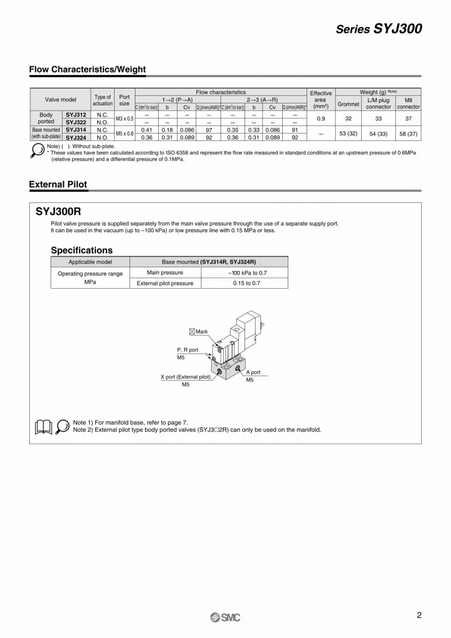
External Pilot
SYJ300RPilot valve pressure is supplied separately from the main valve pressure through the use of a separate supply port.
It can be used in the vacuum (up to –100 kPa) or low pressure line with 0.15 MPa or less.
External pilot pressure
Main pressure
SpecificationsApplicable model
Operating pressure range
MPa
Base mounted (SYJ314R, SYJ324R)
Note 1) For manifold base, refer to page 7.Note 2) External pilot type body ported valves (SYJ3�2R) can only be used on the manifold.
–100 kPa to 0.7
0.15 to 0.7
Flow Characteristics/Weight
Note) ( ): Without sub-plate.
* These values have been calculated according to ISO 6358 and represent the flow rate measured in standard conditions at an upstream pressure of 0.6MPa
(relative pressure) and a differential pressure of 0.1MPa.
SYJ312
SYJ322
SYJ314
SYJ324
C [dm3/(s bar)] b Cv C [dm3/(s bar)] b Cv
1�2 (P�A) 2�3 (A�R) Valve model
Flow characteristics Weight (g) Note)
Type ofactuation
Portsize
M3 x 0.5
Grommet
32
53 (32)
L/M plugconnector
33
54 (33)
M8connector
37
58 (37)M5 x 0.8
N.C. –
–
0.41
0.36
–
–
0.18
0.31
–
–
0.086
0.089
–
–
0.35
0.36
–
–
0.33
0.31
–
–
0.086
0.089
N.O.
N.C.
N.O.
Bodyported
Base mounted(with sub-plate)
0.9
–
Effectivearea (mm2)
P, R port
M5
Mark
X port (External pilot)
M5
A port
M5
Q [l/min(ANR)]*
–
–
97
92
Q [l/min(ANR)]*
–
–
91
92
3
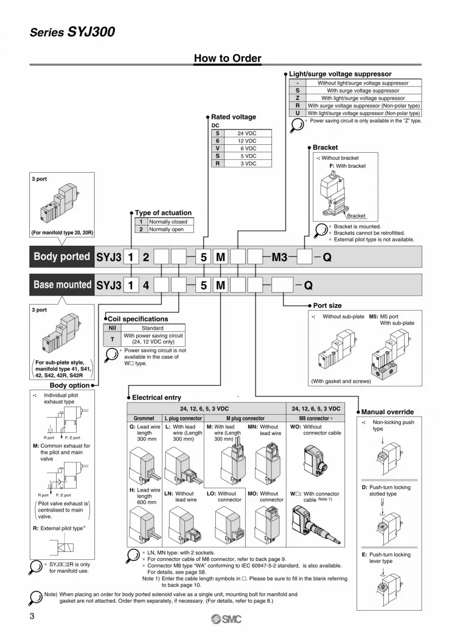
How to Order
SYJ3 2 5 M M3
SYJ3 4 5 M
1
1
1
2
Normally closed
Normally open
Type of actuation
5
6
V
S
R
24 VDC
12 VDC
6 VDC
5 VDC
3 VDC
Rated voltageDC
3 port
(For manifold type 20, 20R)
3 port
For sub-plate style,
manifold type 41, S41,
42, S42, 42R, S42R
Body option
-: Individual pilot
exhaust type
M: Common exhaust for
the pilot and main
valve
R: External pilot type∗
Pilot valve exhaust is
centralised to main
valve.
∗ SYJ3�2R is only
for manifold use.
-
S
Z
R
U
Without light/surge voltage suppressor
With surge voltage suppressor
With light/surge voltage suppressor
With surge voltage suppressor (Non-polar type)
With light/surge voltage suppressor (Non-polar type)
Light/surge voltage suppressor
Bracket
Port size
-: Without sub-plate
(With gasket and screws)
M5: M5 port
With sub-plate
Manual override
-: Non-locking push
type
D: Push-turn locking
slotted type
E: Push-turn locking
lever type
Electrical entry
G: Lead wire length 300 mm
L: With lead wire (Length 300 mm)
M: With lead wire (Length 300 mm)
MN: Without
lead wire
WO: Without connector cable
H: Lead wire length 600 mm
LN: Without lead wire
LO: Without connector
MO: Without connector
∗ LN, MN type: with 2 sockets.
∗ For connector cable of M8 connector, refer to back page 9.
∗ Connector M8 type “WA” conforming to IEC 60947-5-2 standard, is also available.
For details, see page 58.
Note 1) Enter the cable length symbols in �. Please be sure to fill in the blank referring
to back page 10.
∗ Power saving circuit is only available in the "Z" type.
24, 12, 6, 5, 3 VDC 24, 12, 6, 5, 3 VDC
Grommet L plug connector M plug connector M8 connector ∗
R port P, E port
R port P, E port
Body ported
Base mounted
-: Without bracket
F: With bracket
∗ Bracket is mounted.
∗ Brackets cannot be retrofitted.
∗ External pilot type is not available.
Bracket
Note) When placing an order for body ported solenoid valve as a single unit, mounting bolt for manifold and
gasket are not attached. Order them separately, if necessary. (For details, refer to page 8.)
Nil
T
Standard
With power saving circuit(24, 12 VDC only)
Coil specifications
∗ Power saving circuit is not
available in the case of
W� type.
-+
–+–+
–+
+– +–
W�: With connector cable Note 1)
Q
Q
Series SYJ300
4
Series SYJ300
V111
-
S
Z
R
U
56VSR
G
H
L
LN
LO
M
MN
MO
WO
W�
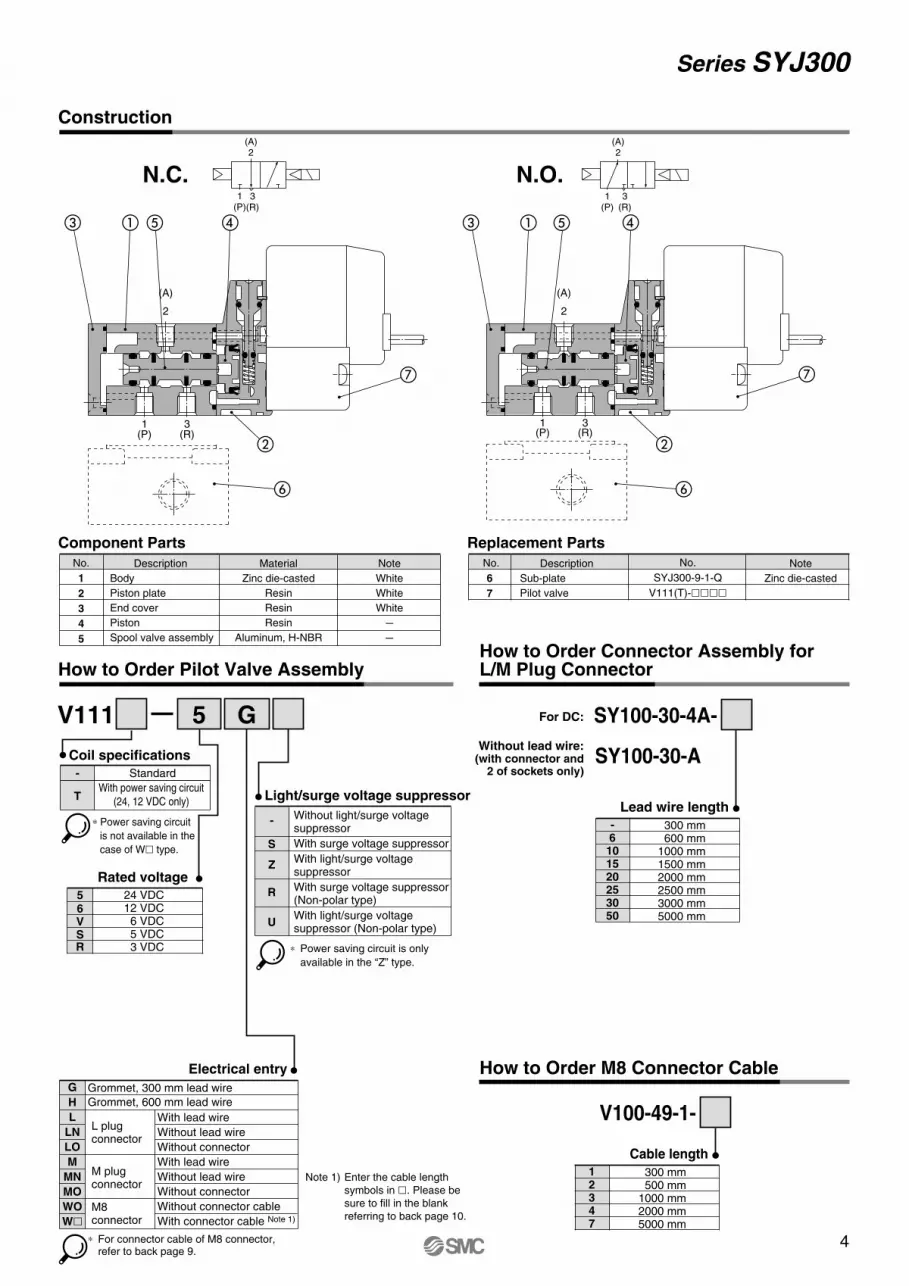
Construction
Component Parts Replacement Parts
No.
1
2
3
4
5
Description
Body
Piston plate
End cover
Piston
Spool valve assembly
Material
Zinc die-casted
Resin
Resin
Resin
Aluminum, H-NBR
Note
White
White
White
–
–
No.
6
7
Description
Sub-plate
Pilot valve
Note
Zinc die-casted
No.
SYJ300-9-1-Q
V111(T)-����
How to Order Pilot Valve AssemblyHow to Order Connector Assembly for L/M Plug Connector
5 G
Electrical entry
Light/surge voltage suppressor
Rated voltage
Grommet, 300 mm lead wire
Grommet, 600 mm lead wire
With lead wire
Without lead wire
Without connector
With lead wire
Without lead wire
Without connector
Without connector cable
With connector cable Note 1)
L plug connector
Without light/surge voltage suppressor
With surge voltage suppressor
With light/surge voltage suppressor
With surge voltage suppressor (Non-polar type)
With light/surge voltage suppressor (Non-polar type)
For DC:
Without lead wire:(with connector and
2 of sockets only)
SY100-30-4A-
SY100-30-A
-6
101520253050
300 mm 600 mm1000 mm1500 mm2000 mm2500 mm3000 mm5000 mm
Lead wire length
�� � �
�
�
�
�� � �
�
�
�
(A)2
1(P)
3(R)
(A)2
1(P)
3(R)
N.C. N.O.
M plug connector
M8 connector
How to Order M8 Connector Cable
V100-49-1-
12347
300 mm 500 mm1000 mm2000 mm5000 mm
Cable length
∗ For connector cable of M8 connector, refer to back page 9.
3(R)
1(P)
(A)
2
3(R)
1(P)
(A)
2
-
T
Standard
With power saving circuit
(24, 12 VDC only)
Coil specifications
∗ Power saving circuit
is not available in the
case of W� type.
∗ Power saving circuit is only
available in the “Z” type.
24 VDC12 VDC
6 VDC5 VDC3 VDC
Note 1) Enter the cable length
symbols in �. Please be
sure to fill in the blank
referring to back page 10.
5
Series SYJ300
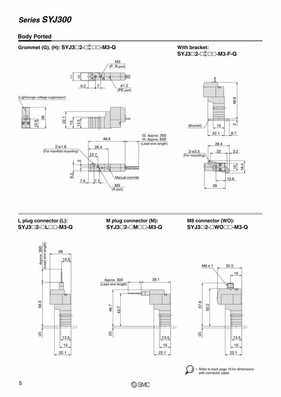
Grommet (G), (H): SYJ3�2-�GH ��-M3-Q
L plug connector (L):
SYJ3�2-�L��-M3-Q
M plug connector (M):
SYJ3�2-�M��-M3-Q
M8 connector (WO):
SYJ3�2-�WO��-M3-Q
Body Ported
With bracket:
SYJ3�2-�GH ��-M3-F-Q
∗ Refer to back page 10 for dimensions with connector cable.
248.6
6.7
28
12.6
3.2
-+
28.4
22
16.4
10
22.1
15
2-ø3.5(For mounting)
(Bracket)
58.5
(2)
Ap
pro
x. 300
(Le
ad
wire
le
ng
th)
12.6
28
22.1
13.5
15
(2)
48.7
43.7
Approx. 300(Lead wire length)
39.1
22.1
13.5
15
57.6
(2)
50.2
32.5
15
M8 x 1
22.1
13.5
15
2
48.6
11
10
79.2
28
12.6 22.1
15
13.5
7.17.4M3
(A port)
8.2
ø1.2(PE port)
- +
G: Approx. 300H: Approx. 600
(Lead wire length)26.4
12.7
P R
A
(Light/surge voltage suppressor)
M3
(P, R port)
Manual override
2-ø1.8(For manifold mounting)
6
Series SYJ300
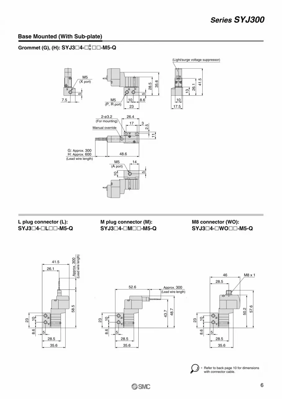
Grommet (G), (H): SYJ3�4-�GH ��-M5-Q
Base Mounted (With Sub-plate)
L plug connector (L):
SYJ3�4-�L��-M5-QM plug connector (M):
SYJ3�4-�M��-M5-Q
M8 connector (WO):
SYJ3�4-�WO��-M5-Q
14
10 5
M5(A port)
2.5
11
48.6
26.4
17 3
G: Approx. 300H: Approx. 600
(Lead wire length)
A
Manual override
2-ø3.2(For mounting)
13
17.5
41.5
26.1
10
(Light/surge voltage suppressor)
+-
5
23
10 8.6
35.6
28.5
R P
M5(P, R port)
5
7.5
M5(X port)
X
Ap
pro
x. 300
(Lead w
ire le
ngth
)
58.5
41.5
26.1
5
23 10
8.6
RP
35.6
28.5
Approx. 300 (Lead wire length)
52.6
48.7
43.7
5
23 10
8.6
RP
35.6
28.5
57.6
50.2
46
28.5
5
23 10
8.6
M8 x 1
RP
35.6
28.5
∗ Refer to back page 10 for dimensions with connector cable.
7
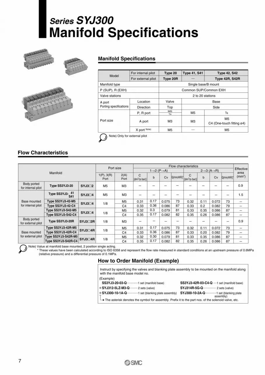
Manifold Specifications
Model
Manifold type
P (SUP), R (EXH)
Valve stations
A port
Porting specifications
Port size
For internal pilot
For external pilot
Type 20
Type 20R
Type 41, S41 Type 42, S42
Type 42R, S42R
Location
Direction
P, R port
A port
X port Note)
Valve
Top
M3
M5
M51/8 M5
M3
Single base/B mount
Common SUP/Common EXH
2 to 20 stations
Base
Side
1/8
M5
M5
C4 (One-touch fitting ø4)
Note) Only for external pilot
How to Order Manifold (Example)
Instruct by specifying the valves and blanking plate assembly to be mounted on the manifold along
with the manifold base model no.
(Example)
SS3YJ3-20-03-Q.............1 set (manifold base)
SYJ312-5LZ-M3-Q......... 2 sets (valve)
SYJ300-10-1A-Q.............1 set (blanking plate assembly)
SS3YJ3-42R-03-C4-Q ....1 set (manifold base)
SYJ314R-5G-Q............... 2 sets (valve)
SYJ300-10-2A-Q.............1 set (blanking plate assembly)
Manifold SpecificationsSeries SYJ300
Flow Characteristics
Note) Value at manifold base mounted, 2 position single acting.
* These values have been calculated according to ISO 6358 and represent the flow rate measured in standard conditions at an upstream pressure of 0.6MPa
(relative pressure) and a differential pressure of 0.1MPa.
Type SS3YJ3-20
Type SS3YJ3- 41
S41
Type SS3YJ3-42-M5
Type SS3YJ3-20R
Type SS3YJ3-42-C4
Type SS3YJ3-42R-M5
Type SS3YJ3-42R-C4
Type SS3YJ3-S42R-M5
Type SS3YJ3-S42R-C4
Type SS3YJ3-S42-M5
Type SS3YJ3-S42-C4
C
[dm3/(s bar)]
1(P), 3(R)
Port
2(A)
Port b CvC
[dm3/(s bar)]b Cv
1�2 (P�A) 2�3 (A�R)Manifold
Flow characteristicsEffective
area (mm2)
Port size
M5
M5
1/8
1/8
M3
C4
M3
M5
M5
C4
M5
C4
M5
C4
M3
–
–
0.31
0.33
0.32
0.35
–
0.31
0.33
0.32
0.35
–
–
–
–
0.075
0.086
0.079
0.082
–
0.075
0.086
0.079
0.082
–
–
0.32
0.33
0.33
0.35
–
0.32
0.33
0.33
0.35
–
–
0.11
0.2
0.35
0.26
–
0.11
0.20
0.35
0.26
–
–
0.072
0.082
0.086
0.086
–
0.072
0.082
0.086
0.086
0.9
1.5
–
–
–
–
0.9
–
–
–
–
1/8
1/8
1/8
SYJ3�2
SYJ3�4
SYJ3�4
SYJ3�4
SYJ3�2R
SYJ3�4R
SYJ3�4R
Body ported
for internal pilot
Base mounted
for internal pilot
Body ported
for external pilot
Base mounted
for external pilot
0.17
0.36
0.3
0.17
–
0.17
0.36
0.30
0.17
∗∗
The asterisk denotes the symbol for assembly. Prefix it to the part nos. of the solenoid valve, etc.
Q[l/min(ANR)]*
–
–
73
87
81
82
–
73
87
81
82
Q[l/min(ANR)]*
–
–
73
79
87
87
–
73
79
87
87
8
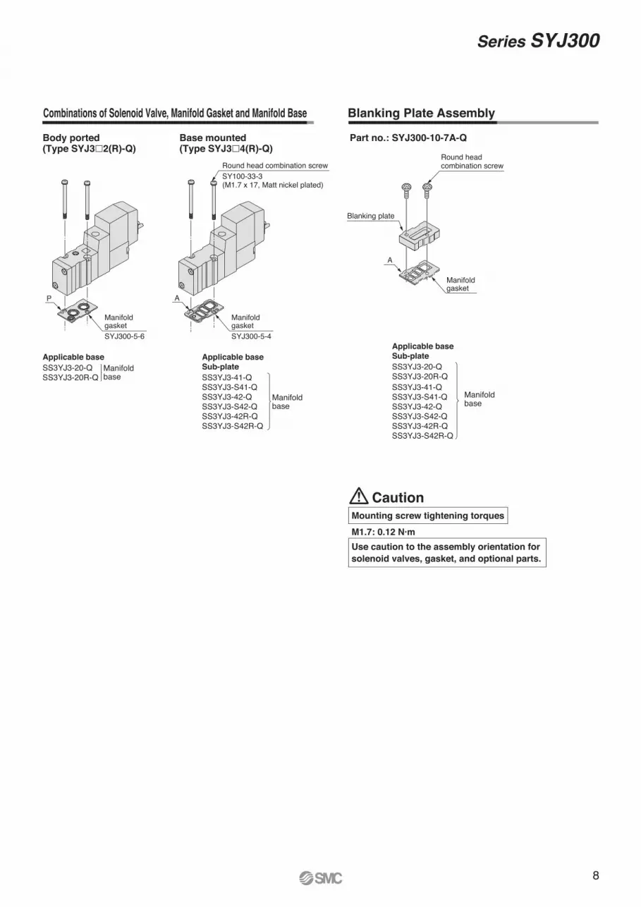
P A
Body ported (Type SYJ3�2(R)-Q)
Base mounted (Type SYJ3�4(R)-Q)
Part no.: SYJ300-10-7A-Q
Applicable base
SS3YJ3-20-QSS3YJ3-20R-Q
Applicable base
Sub-plate
SS3YJ3-41-QSS3YJ3-S41-QSS3YJ3-42-QSS3YJ3-S42-QSS3YJ3-42R-QSS3YJ3-S42R-Q
Applicable base
Sub-plate
SS3YJ3-20-QSS3YJ3-20R-QSS3YJ3-41-QSS3YJ3-S41-QSS3YJ3-42-QSS3YJ3-S42-QSS3YJ3-42R-QSS3YJ3-S42R-Q
Manifoldbase
Manifoldbase
Manifoldbase
P
Manifold gasket SYJ300-5-6
Manifold gasket
A
Round head combination screwSY100-33-3(M1.7 x 17, Matt nickel plated)
Round head combination screw
Blanking plate
A
Manifold gasket SYJ300-5-4
Combinations of Solenoid Valve, Manifold Gasket and Manifold Base Blanking Plate Assembly
Series SYJ300
CautionMounting screw tightening torques
M1.7: 0.12 N·m
Use caution to the assembly orientation for
solenoid valves, gasket, and optional parts.
XP
R
A
A
P
R
A
–+–+
–+–+
R
P
PR
9
Series SYJ300
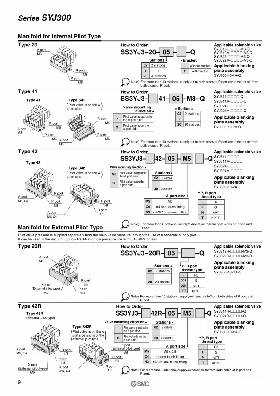
Type 20
Type 41
Type 42
Type 20R
Type 42R
Note) For more than 8 stations, supply/exhaust air to/from both sides of P port and R port.
Type 41 Type S41
Pilot valve is on the A port side.
Type 42
Type S42
Pilot valve is on the A port side.
Type 42R(External pilot type)
How to Order
Applicable blankingplate assemblySYJ300-10-1A-Q
Applicable solenoid valveSYJ314-����-Q
SYJ314M-����-Q
SYJ324-����-Q
SYJ324M-����-Q
Applicable blankingplate assemblySYJ300-10-2A-Q
Applicable solenoid valveSYJ314-����SYJ314M-����SYJ324-����SYJ324M-����
Applicable blankingplate assemblySYJ300-10-2A
Applicable solenoid valveSYJ312R-����-M3-Q
SYJ322R-����-M3-Q
Applicable blankingplate assemblySYJ300-10 -1A-Q
Applicable solenoid valveSYJ314R-����-Q
SYJ324R-����-Q
Applicable blankingplate assemblySYJ300-10-2A-Q
Note) For more than 10 stations, supply air to both sides of P port and exhaust air from both sides of R port.
SS3YJ3--20-- 05 -- --Q
Note) For more than 10 stations, supply air to both sides of P port and exhaust air from both sides of R port.
Note) For more than 10 stations, supply/exhaust air to/from both sides of P port and R port.
How to Order
SS3YJ3-- 41-- 05 --M3--Q
How to Order
SS3YJ3-- 42R-- 05 -- M5 --Q
-
F
Without bracket
With bracket
Bracket
M5
C4
N3
M5 x 0.8
ø4 one-touch fitting
ø5/32" one-touch fitting
A port size
How to Order
SS3YJ3--20R-- 05 --Q
How to Order
SS3YJ3-- 42-- 05 -- M5 --Q
M5
C4
N3
M5
ø4 one-touch fitting
ø5/32" one-touch fitting
A port size
( )
( )
Pilot valve pressure is supplied separately from the main valve pressure through the use of a separate supply port.
It can be used in the vacuum (up to –100 kPa) or low pressure line with 0.15 MPa or less.
Manifold for Internal Pilot Type
Manifold for External Pilot Type
Type S42R
Pilot valve is on the A port side and is of the external pilot type.
( )
P port
R port
A port
M3
M5
M5
P port
R port
1/8
1/8
A portM3
P port
R port
M5
M5
A port
M3
P port
M5
A port
M5, C4 P port
R port
1/8
1/8
A portM3
R port
P port
1/8
1/8
P port
R port
1/8
1/8X port(External pilot type)
M5
P port
R port
1/8
1/8
X port(External pilot type)
M5
A portM5, C4
A port
M5, C4
R port
M5
A port
M5, C4
X port(External pilot type)
M5
Pilot valve is opposite the A port side.
Pilot valve is on the A port side.
Valve mountingdirection
S
-
02
:
20
2 stations
:
20 stations
Stations
02
:
20
2 stations
:
20 stations
Stations
02
:
20
2 stations
:
20 stations
Stations
02
:
20
2 stations
:
20 stations
Stations
-
F
N
T
Rc
G
NPT
NPTF
P, R portthread type
02
:
20
2 stations
:
20 stations
Stations
Pilot valve is opposite the A port side.
Pilot valve is on the A port side.
Valve mounting direction
S
-
Pilot valve is opposite the A port side.
Pilot valve is on the A port side.
Valve mounting direction
S
Nil
Applicable solenoid valveSYJ312-����-M3-QSYJ312M-����-M3-QSYJ322-����-M3-QSYJ322M-����-M3-Q
-
00F
00N
00T
Rc
G
NPT
NPTF
P, R portthread type
-
F
N
T
Rc
G
NPT
NPTF
P, R portthread type
Note) For more than 8 stations, supply/exhaust air to/from both sides of P port and R port.
A
AP
R
A
A
A
A
XP
R
A
A X
PR
–+–+
–+–+
10
Series SYJ300
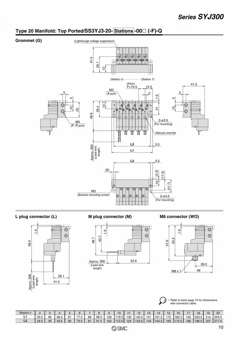
Station n
L1
L2
2
35.5
28.5
3
46
39
4
56.5
49.5
5
67
60
6
77.5
70.5
7
88
81
8
98.5
91.5
9
109
102
10
119.5
112.5
11
130
123
12
140.5
133.5
13
151
144
14
161.5
154.5
15
172
165
16
182.5
175.5
17
193
186
18
203.5
196.5
19
214
207
20
224.5
217.5
Type 20 Manifold: Top Ported/SS3YJ3-20- Stations -00� (-F)-Q
Grommet (G)
L plug connector (L) M plug connector (M) M8 connector (WO)
Ap
pro
x. 300
(Le
ad
wire
le
ng
th)
1.9
26.1
41.5
58.5
52.6Approx. 300 (Lead wire
length)
1.9
43.7
48.7
M8 x 1 46
28.5
57.6 50.2
1.9
∗ Refer to back page 10 for dimensions with connector cable.
(2.3
)
(21.7
)
(17.5
)
103.5L2
(6)
2-ø3.5(For mounting)
M3(Bracket mounting screw)
48.6
26.4 1
2.7
1.9
Ap
pro
x. 300
(Le
ad
wire
le
ng
th)
3.5
L1
L2
(Pitch)P=10.5 12.5
2
21
2-ø3.5(For mounting)
M3(A port)
R
RP
P
Manual override
AAAAA
5
10
5
41.5
5
10
5
25
M5(P, R port)
41.5
26.1
13
(Light/surge voltage suppressor)
+- +- +- +- +-
(Station 1)(Station n)
11
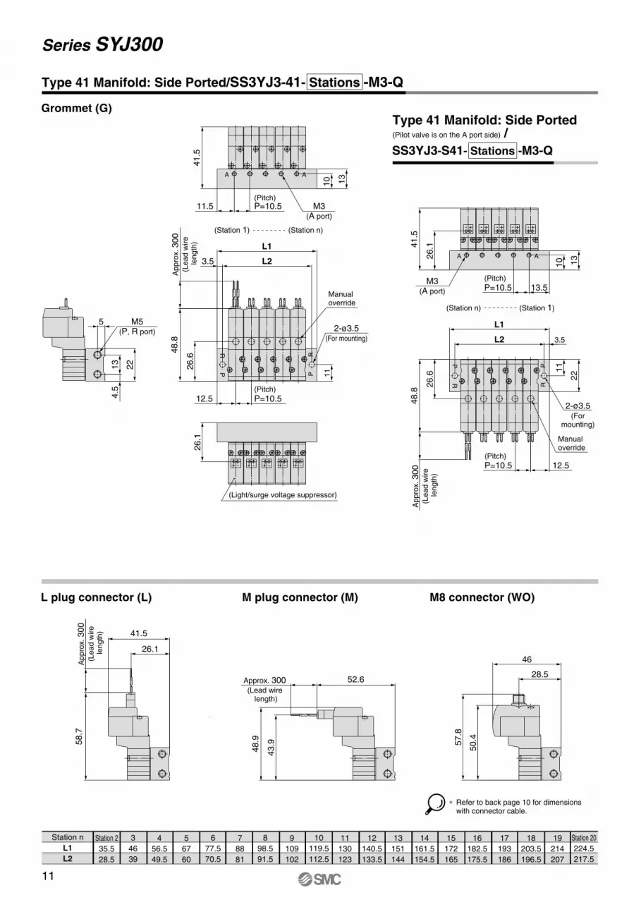
Series SYJ300
Station n
L1
L2
Station 2
35.5
28.5
3
46
39
4
56.5
49.5
5
67
60
6
77.5
70.5
7
88
81
8
98.5
91.5
9
109
102
10
119.5
112.5
11
130
123
12
140.5
133.5
13
151
144
14
161.5
154.5
15
172
165
16
182.5
175.5
17
193
186
18
203.5
196.5
19
214
207
Station 20
224.5
217.5
Type 41 Manifold: Side Ported/SS3YJ3-41- Stations -M3-Q
SS3YJ3-S41- Stations -M3-Q
Grommet (G)Type 41 Manifold: Side Ported(Pilot valve is on the A port side) /
L plug connector (L) M plug connector (M) M8 connector (WO)
26.1
(Light/surge voltage suppressor)
+- +- +- +- +-
3.5
L1
L2
112
6.6
Appro
x. 300
(Lead w
ire
length
)
48.8
(Pitch)
P=10.512.5
PR
PR
2-ø3.5(For mounting)
Manual override
4.5
22
5
13
M5(P, R port)
(Pitch)P=10.511.5
41.5
A A
M3(A port)
(Station 1) (Station n)
13
10
(Pitch)
P=10.5 13.5M3
(A port)
AA
41.5
26.1
+- +- +- +- +-
221
1
12.5(Pitch)
P=10.5
3.5L2
L1
Appro
x. 300
(Lead w
ire
length
)Manual override
48.8
26.6
2-ø3.5(For
mounting)
PR
PR
57.8
50.4
46
28.552.6Approx. 300
(Lead wire length)
43.9
48.9
Appro
x. 300
(Lead w
ire
length
)
58.7
41.5
26.1
∗ Refer to back page 10 for dimensions with connector cable.
13
10
(Station n) (Station 1)
12
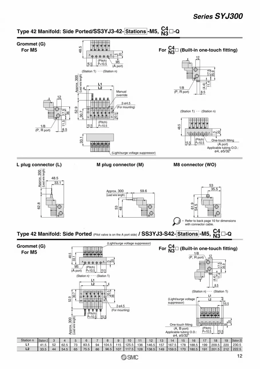
Series SYJ300
Station n
L1
L2
Station 2
41.5
33.5
3
52
44
4
62.5
54.5
5
73
65
6
83.5
75.5
7
94
86
8
104.5
96.5
9
115
107
10
125.5
117.5
11
136
128
12
146.5
138.5
13
157
149
14
167.5
159.5
15
178
170
16
188.5
180.5
17
199
191
18
209.5
201.5
19
220
212
Station 20
230.5
222.5
Type 42 Manifold: Side Ported/SS3YJ3-42- Stations -M5, �-Q
Grommet (G)
For M5
Grommet (G)
For M5
For � (Built-in one-touch fitting)
L plug connector (L) M plug connector (M) M8 connector (WO)
33.1
(Light/surge voltage suppressor)
+- +- +- +- +-
36
17.5
11.5
12
8.51/8
(P, R port)
52.9
4
20
.5
L1L2
(Pitch)P=10.515.5
Ap
pro
x. 300
(Lea
d w
ire le
ngth
)30.7
2-ø4.5
(For mounting)
PR
PR
Manual override
(Pitch)P=10.515.5
205
48.5
M5(A port)
AA
(Station 1) (Station n)
35.9
11.4
17.5
8.5
12
(4.4
)
1/8(P, R port)
(Pitch)P=10.515.5
20
48.5
5
One-touch fitting
(A port)Applicable tubing O.D.:
ø4, ø5/32"
AA
52.9
4L2L1
36
20.5
15.5(Pitch)P=10.5
30.7
2-ø4.5(For mounting)
(Station 1)(Station n)
PR
PR
Ap
pro
x. 300
(Lea
d w
ire le
ngth
)
(Light/surge voltage suppressor)
(Pitch)P=10.5 15.5
205
48.5
33.1
M5(A port)
AA
+- +- +- +- +-
1/8(P, R port)
35.9
11.4
17.5
8.5
12
(4.4
)
(Light/surge voltage suppressor)
L1
4L2
15.5
(Pitch)P=10.5 15.5
205One-touch fitting
(A, B port)Applicable tubing O.D.:
ø4, ø5/32"
AA
+- +- +- +- +-
Ap
pro
x. 300
(Lea
d w
ire le
ngth
)
62.8
48.5
33.1
59.6Approx. 300 (Lead wire length)
4853
61.9
54.5
5335.5
C4N3
For � (Built-in one-touch fitting)C4N3
C4N3
Type 42 Manifold: Side Ported (Pilot valve is on the A port side) / SS3YJ3-S42- Stations -M5, �-QC4N3
(Station 1) (Station n)
∗ Refer to back page 10 for dimensions with connector cable.
(Station n) (Station 1)
13
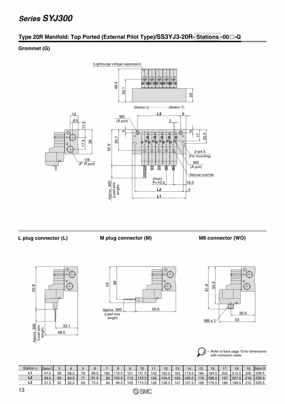
Series SYJ300
Station n
L1
L2
L3
Station 2
47.5
39.5
31.5
3
58
50
42
4
68.5
60.5
52.5
5
79
71
63
6
89.5
81.5
73.5
7
100
92
84
8
110.5
102.5
94.5
9
121
113
105
10
131.5
123.5
115.5
11
142
134
126
12
152.5
144.5
136.5
13
163
155
147
14
173.5
165.5
157.5
15
184
176
168
16
194.5
186.5
178.5
17
205
197
189
18
215.5
207.5
199.5
19
226
218
210
Station 20
236.5
228.5
220.5
L plug connector (L) M plug connector (M) M8 connector (WO)
Type 20R Manifold: Top Ported (External Pilot Type)/SS3YJ3-20R- Stations -00�-Q
Grommet (G)
12
8.5
36
17.5
11.5
1/8(P, R port)
PR
52.9
M5(X port)
5
L3 8
18.5(Pitch)P=10.5
4L2
2
Ap
pro
x. 300
(Le
ad
wire
le
ng
th)
30.7
17
20.5
5
L1
X X
2-ø4.5(For mounting)
M3(A port)
Manual override
A
XA
X
A
X
A
X
A
X
48.5
33.1
20
(Light/surge voltage suppressor)
(Station 1)(Station n)
+- +- +- +- +-
Ap
pro
x. 300
(Le
ad
wire
le
ng
th)
62.8
48.5
33.1
PR
59.6Approx. 300 (Lead wire
length)
48
53
PR
53
35.5
61.9 54.5
PR
M8 x 1
∗ Refer to back page 10 for dimensions with connector cable.
14
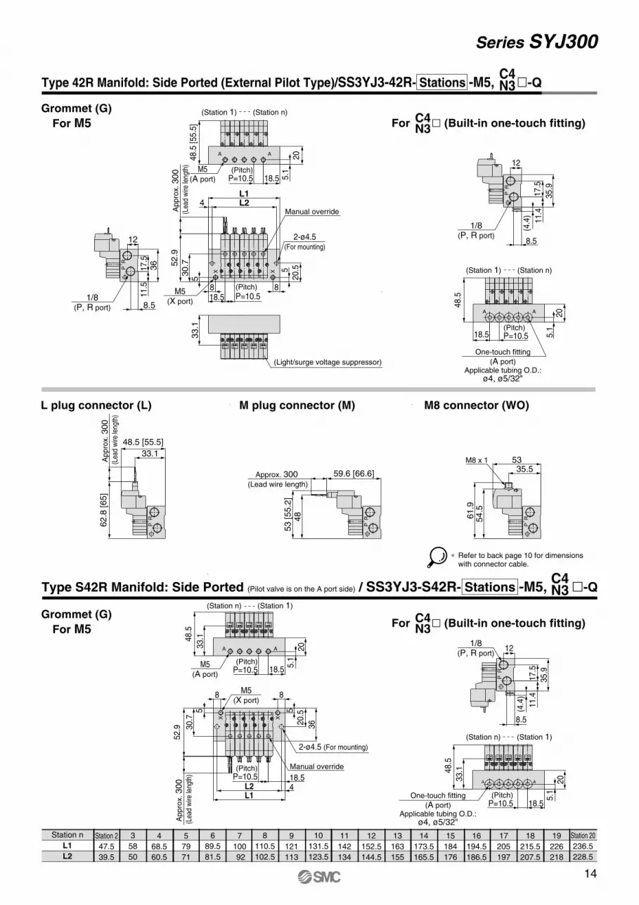
Series SYJ300
Station 2
47.5
39.5
3
58
50
4
68.5
60.5
5
79
71
6
89.5
81.5
7
100
92
8
110.5
102.5
9
121
113
10
131.5
123.5
11
142
134
12
152.5
144.5
13
163
155
14
173.5
165.5
15
184
176
16
194.5
186.5
17
205
197
18
215.5
207.5
19
226
218
Station 20
236.5
228.5
Type 42R Manifold: Side Ported (External Pilot Type)/SS3YJ3-42R- Stations -M5, �-Q
Station n
L1
L2
L plug connector (L) M plug connector (M) M8 connector (WO)
33.1
(Light/surge voltage suppressor)
+-+- +- +- +-
52.9
45
L1L2
20.55
88 (Pitch)
P=10.518.5
Ap
pro
x. 300
(Lea
d w
ire le
ngth
)30.7
X X
Manual override
12
8.5
36
17.5
11.5
1/8(P, R port)
RP
20
5.1(Pitch)
P=10.5 18.5
48.5
[55.5
]
AA
M5(A port)
(Station 1) (Station n)
35.9
11.4
12
8.5
17.5
(4.4
)
1/8(P, R port)
RP
20
(Pitch)P=10.518.5 5
.1
48.5
AA
One-touch fitting
(A port)Applicable tubing O.D.:
ø4, ø5/32"
Ap
pro
x. 300
(Lea
d w
ire le
ngth
)
62.8
[65]
48.5 [55.5]
33.1
RP
59.6 [66.6]Approx. 300 (Lead wire length)
53 [55.2
]48
RP
61.9
54.5
5335.5
M8 x 1
RP
52.9
88
4L1L2
5
3620.55
Manual override
18.5(Pitch)
P=10.5
Ap
pro
x. 300
(Lea
d w
ire le
ngth
)30.7
M5(X port)
X X
2-ø4.5 (For mounting)
(Pitch)P=10.5 18.5
20
5.1
48.5
33.1
M5(A port)
(Station 1)(Station n)
AA
+- +- +- +- +-
(Pitch)P=10.5 18.5
20
5.1
48.5
33.1
AA
+- +- +- +- +-
1/8(P, R port)
35.9
11.4
12
8.5
17.5R
P
(4.4
)
C4N3
Type S42R Manifold: Side Ported (Pilot valve is on the A port side) / SS3YJ3-S42R- Stations -M5, �-Q
(Station 1) (Station n)
(Station n) (Station 1)
One-touch fitting
(A port)Applicable tubing O.D.:
ø4, ø5/32"
∗ Refer to back page 10 for dimensions with connector cable.
Grommet (G)
For M5
Grommet (G)
For M5
M5(X port)
For � (Built-in one-touch fitting)C4N3
For � (Built-in one-touch fitting)C4N3
C4N3
2-ø4.5(For mounting)
15
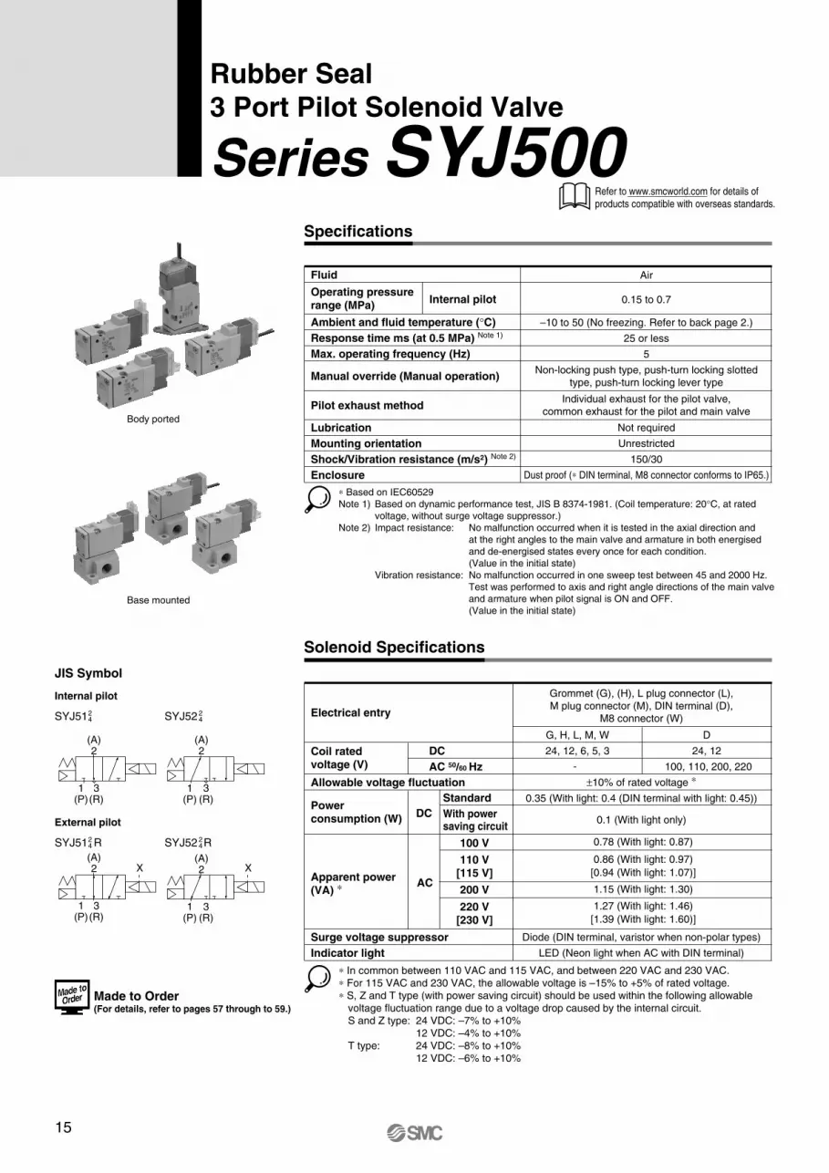
Series SYJ500
Rubber Seal3 Port Pilot Solenoid Valve
JIS Symbol
Internal pilot
SYJ5124 SYJ52 2
4
External pilot
SYJ51 R24 SYJ52 R2
4
Body ported
Base mounted
X X
(A)2
1(P)
3(R)
(A)2
1(P)
3(R)
(A)2
1(P)
3(R)
(A)2
1(P)
3(R)
Order
Made
Solenoid Specifications
Electrical entry
Coil rated voltage (V)
DC
AC 50/60 Hz
Standard
With powersaving circuit
Surge voltage suppressor
Indicator light
Power consumption (W)
DC
Apparent power(VA) ∗
AC
100 V
110 V[115 V]
200 V
220 V[230 V]
100, 110, 200, 220
±10% of rated voltage ∗
0.35 (With light: 0.4 (DIN terminal with light: 0.45))
0.1 (With light only)
0.78 (With light: 0.87)
1.15 (With light: 1.30)
0.86 (With light: 0.97)
[0.94 (With light: 1.07)]
1.27 (With light: 1.46)
[1.39 (With light: 1.60)]
Diode (DIN terminal, varistor when non-polar types)
LED (Neon light when AC with DIN terminal)
Grommet (G), (H), L plug connector (L),
M plug connector (M), DIN terminal (D),
M8 connector (W)
∗ In common between 110 VAC and 115 VAC, and between 220 VAC and 230 VAC.
∗ For 115 VAC and 230 VAC, the allowable voltage is –15% to +5% of rated voltage.
∗ S, Z and T type (with power saving circuit) should be used within the following allowable
voltage fluctuation range due to a voltage drop caused by the internal circuit.
S and Z type: 24 VDC: –7% to +10%
12 VDC: –4% to +10%
T type: 24 VDC: –8% to +10%
12 VDC: –6% to +10%
Allowable voltage fluctuation
Specifications
Fluid
Operating pressure range (MPa)
Ambient and fluid temperature (°C)
Response time ms (at 0.5 MPa) Note 1)
Max. operating frequency (Hz)
Manual override (Manual operation)
Pilot exhaust method
Lubrication
Mounting orientation
Shock/Vibration resistance (m/s2) Note 2)
Enclosure
Air
0.15 to 0.7Internal pilot
–10 to 50 (No freezing. Refer to back page 2.)
25 or less
5
Non-locking push type, push-turn locking slotted
type, push-turn locking lever type
Not required
Unrestricted
150/30
Dust proof (∗ DIN terminal, M8 connector conforms to IP65.)
Individual exhaust for the pilot valve,
common exhaust for the pilot and main valve
∗ Based on IEC60529
Note 1) Based on dynamic performance test, JIS B 8374-1981. (Coil temperature: 20°C, at rated
voltage, without surge voltage suppressor.)
Note 2) Impact resistance: No malfunction occurred when it is tested in the axial direction and
at the right angles to the main valve and armature in both energised
and de-energised states every once for each condition.
(Value in the initial state)
Vibration resistance: No malfunction occurred in one sweep test between 45 and 2000 Hz.
Test was performed to axis and right angle directions of the main valve
and armature when pilot signal is ON and OFF.
(Value in the initial state)
Refer to www.smcworld.com for details of
products compatible with overseas standards.
Made to Order (For details, refer to pages 57 through to 59.)
G, H, L, M, W
24, 12, 6, 5, 3
D
24, 12
-
16
Series SYJ500
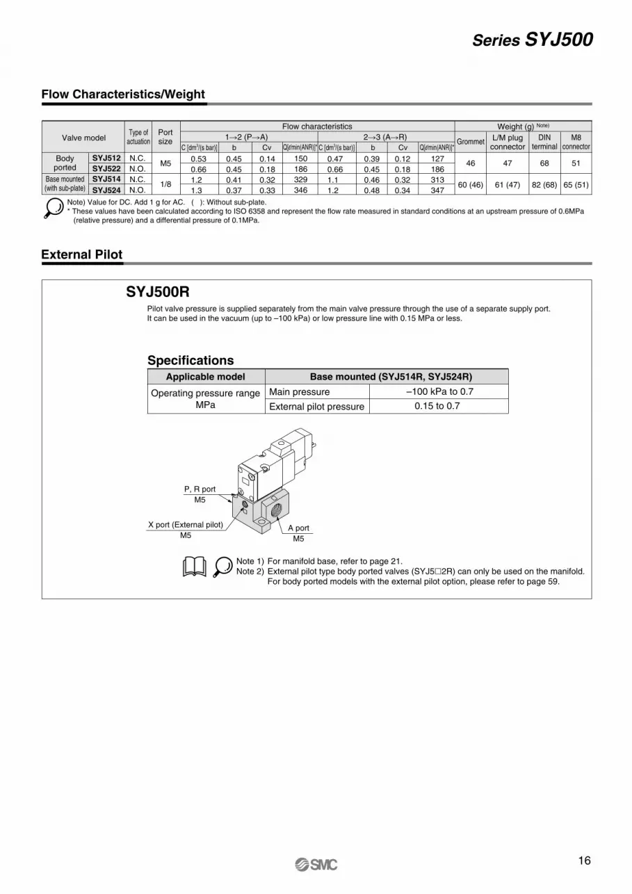
External Pilot
SYJ500RPilot valve pressure is supplied separately from the main valve pressure through the use of a separate supply port.
It can be used in the vacuum (up to –100 kPa) or low pressure line with 0.15 MPa or less.
External pilot pressure
Main pressure
SpecificationsApplicable model
Operating pressure range
MPa
Base mounted (SYJ514R, SYJ524R)
Note 1) For manifold base, refer to page 21.Note 2) External pilot type body ported valves (SYJ5�2R) can only be used on the manifold.
For body ported models with the external pilot option, please refer to page 59.
–100 kPa to 0.7
0.15 to 0.7
Flow Characteristics/Weight
Note) Value for DC. Add 1 g for AC. ( ): Without sub-plate.
* These values have been calculated according to ISO 6358 and represent the flow rate measured in standard conditions at an upstream pressure of 0.6MPa
(relative pressure) and a differential pressure of 0.1MPa.
SYJ512
SYJ522
SYJ514
SYJ524
C [dm3/(s bar)] b Cv C [dm3/(s bar)] b Cv
1�2 (P�A) 2�3 (A�R) Valve model
Flow characteristics Weight (g) Note)
GrommetL/M plugconnector
DINterminal
M5 46
60 (46)
47
61 (47)
68
82 (68)
M8connector
51
65 (51)1/8
N.C. 0.53
0.66
1.2
1.3
0.45
0.45
0.41
0.37
0.14
0.18
0.32
0.33
0.47
0.66
1.1
1.2
0.39
0.45
0.46
0.48
0.12
0.18
0.32
0.34
N.O.
N.C.
N.O.
Bodyported
Base mounted(with sub-plate)
P, R port
M5
X port (External pilot)
M5A port
M5
Type ofactuation
Portsize
Q[l/min(ANR)]*
150
186
329
346
Q[l/min(ANR)]*
127
186
313
347
17
Series SYJ500
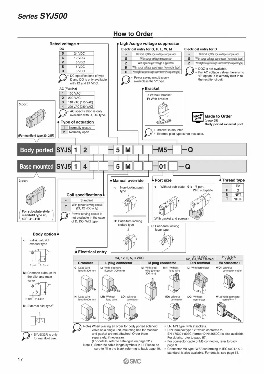
SYJ5 2 5 M M5
SYJ5 4 5 M 01
1
1
1
2
Normally closedNormally open
Type of actuation
5
6
V
S
R
24 VDC12 VDC
6 VDC5 VDC3 VDC
Rated voltage
DC
1
2
3
4
100 VAC200 VAC110 VAC [115 VAC]220 VAC [230 VAC]
AC (50/60 Hz)
3 port
(For manifold type 20, 21R)
3 port
Body option
-: Individual pilot exhaust type
M: Common exhaust for the pilot and main valve
R: External pilot type∗
∗ SYJ5�2R is only for manifold use.
Bracket
-: Without bracketF: With bracket
Port size
-: Without sub-plate
(With gasket and screws)
01: 1/8 port With sub-plate
Manual override
D: Push-turn locking slotted type E: Push-turn locking
lever type
Electrical entry
R port P, E port
R port P, E port
Electrical entry for G, H, L, W, M
- Without light/surge voltage suppressor With surge voltage suppressor
With light/surge voltage suppressor With surge voltage suppressor (Non-polar type)With light/surge voltage suppressor (Non-polar type)
S
Z
R
U
Electrical entry for D
- Without light/surge voltage suppressor With surge voltage suppressor (Non-polar type)With light/surge voltage suppressor (Non-polar type)
S
Z
∗ Power saving circuit is only available in the “Z” type.
∗ DOZ is not available.∗ For AC voltage valves there is no “S” option. It is already built-in to the rectifier circuit.
Light/surge voltage suppressor
Body ported
Base mounted
∗ Bracket is mounted.∗ External pilot type is not available.
∗ DC specifications of type D and DO is only available with 12 and 24 VDC.
∗ AC specification is only available with D, DO type.
∗ Power saving circuit is not available in the case of D, DO, W� type.
Rc
NPTNPTF
G
Thread type
N
T
F
-
G: Lead wire length 300 mm
L: With lead wire (Length 300 mm)
M: With lead wire (Length 300 mm)
MN: Without lead wire
D: With connector
H: Lead wire length 600 mm
LN: Without lead wire
LO: Without connector
MO: Without connector
DO: Without connector
WO: Without connector cable
W�: With connector cable Note 1)
Grommet L plug connector
24, 12, 6, 5, 3 VDC24, 12 VDC/
100, 110, 200, 220 VAC24, 12, 6, 5,
3 VDC
M plug connector DIN terminal M8 connector ∗
Note) When placing an order for body ported solenoid valve as a single unit, mounting bolt for manifold and gasket are not attached. Order them separately, if necessary. (For details, refer to catalogue on page 22.)Note 1) Enter the cable length symbols in �. Please be
sure to fill in the blank referring to back page 10.
∗ LN, MN type: with 2 sockets.∗ DIN terminal type "Y" which conforms to EN-175301-803C (former DIN43650C) is also available. For details, refer to page 57. ∗ For connector cable of M8 connector, refer to back page 9.∗ Connector M8 type “WA” conforming to IEC 60947-5-2 standard, is also available. For details, see page 58.
-
T
Standard With power saving circuit
(24, 12 VDC only)
Coil specifications
-: Non-locking push type
–+
–+ -+
–++–
+–
How to Order
For sub-plate style,
manifold type 40,
40R, 41, 41R
Q
Q
Made to Order(page 59)Body ported external pilot
18
Series SYJ500
V111
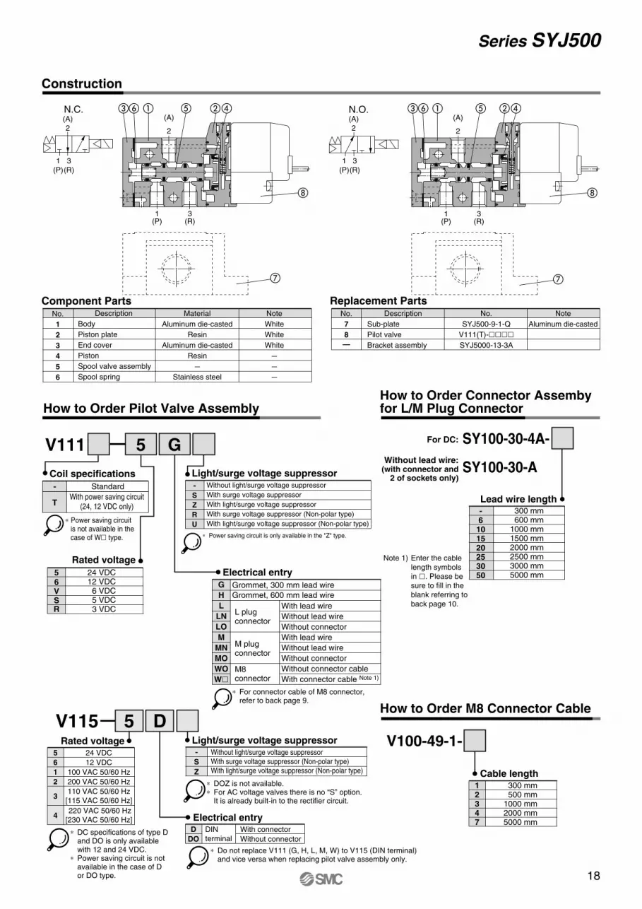
Construction
Component Parts Replacement PartsNo.
1
2
3
4
5
6
Description
Body
Piston plate
End cover
Piston
Spool valve assembly
Spool spring
Material
Aluminum die-casted
Resin
Aluminum die-casted
Resin
–
Stainless steel
Note
White
White
White
–
–
–
No.
7
8
—
Description
Sub-plate
Pilot valve
Bracket assembly
Note
Aluminum die-casted
No.
SYJ500-9-1-Q
V111(T)-����SYJ5000-13-3A
How to Order Pilot Valve Assembly
5 G
Cable length
N.C. N.O.
How to Order M8 Connector Cable
V100-49-1-
12347
300 mm 500 mm1000 mm2000 mm5000 mm
-S
Z
R
U
Light/surge voltage suppressorWithout light/surge voltage suppressor
With surge voltage suppressor
With light/surge voltage suppressor
With surge voltage suppressor (Non-polar type)
With light/surge voltage suppressor (Non-polar type)
∗ Power saving circuit is only available in the "Z" type.
5 DV115
5 24 VDC
6 12 VDC
1 100 VAC 50/60 Hz
2 200 VAC 50/60 Hz
3
4 220 VAC 50/60 Hz
[230 VAC 50/60 Hz]
110 VAC 50/60 Hz
[115 VAC 50/60 Hz]
DIN
terminal
D With connector
DO Without connector
- Without light/surge voltage suppressor
With surge voltage suppressor (Non-polar type)
With light/surge voltage suppressor (Non-polar type)S
Z
∗ DOZ is not available.∗ For AC voltage valves there is no “S” option.
It is already built-in to the rectifier circuit.
∗ Do not replace V111 (G, H, L, M, W) to V115 (DIN terminal) and vice versa when replacing pilot valve assembly only.
Rated voltage
Electrical entry
Light/surge voltage suppressor
∗ DC specifications of type D and DO is only available with 12 and 24 VDC.
∗ Power saving circuit is not available in the case of D or DO type.
(A)
2
1(P)
3(R)
1(P)
3(R)
(A)
2
� �
(A)
2
1
(P)
3
(R)
(A)
2
1
(P)
3
(R)
�� � � ��
�� � � ��
Electrical entry
How to Order Connector Assemby for L/M Plug Connector
For DC:
Without lead wire:(with connector and
2 of sockets only)
SY100-30-4A-
SY100-30-A
-6
101520253050
300 mm 600 mm1000 mm1500 mm2000 mm2500 mm3000 mm5000 mm
Lead wire length
56VSR
Rated voltage
-
T
Standard
With power saving circuit
(24, 12 VDC only)
Coil specifications
∗ Power saving circuit is not available in the case of W� type.
24 VDC12 VDC
6 VDC5 VDC3 VDC
G
H
L
LN
LO
M
MN
MO
WO
W�
Grommet, 300 mm lead wire
Grommet, 600 mm lead wire
With lead wire
Without lead wire
Without connector
With lead wire
Without lead wire
Without connector
Without connector cable
With connector cable Note 1)
L plug connector
M plug connector
M8 connector
∗ For connector cable of M8 connector, refer to back page 9.
Note 1) Enter the cable
length symbols
in �. Please be
sure to fill in the
blank referring to
back page 10.
19
Series SYJ500
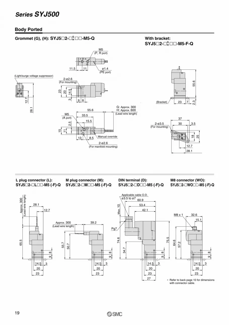
Body Ported
Grommet (G), (H): SYJ5�2-�GH ��-M5-Q With bracket:
SYJ5�2-�GH ��-M5-F-Q
L plug connector (L):
SYJ5�2-�L��-M5 (-F)-QM plug connector (M):
SYJ5�2-�M��-M5 (-F)-QDIN terminal (D):
SYJ5�2-�D��-M5 (-F)-QM8 connector (WO):
SYJ5�2-�WO��-M5 (-F)-Q
50.7
39.2Approx. 300(Lead wire length)
28.1
57.2
64.6
15.1
32.6
Max. 10
74.6
60.9
53.4
42.1
27
89
14.5 3
23
20
12.7
89
14.5 3
23
20
89
14.5 3
23
20
∗ Refer to back page 10 for dimensions with connector cable.
M8 x 1
Applicable cable O.D.
ø3.5 to ø7
Pg7
34.7
75.5
89
3
23
14.5
20
Appro
x. 300
(Lead w
ire length
)
65.5
55.7
2.3
55.6
12.7
28.1
23 7
2-ø3.5(For mounting)
25
18
3.5
37
30
-+
(Bracket)
11
15
12.7
28.1
55.6
2.5
89
14.5
3
23
20
15.5
8.513
1111.5 ø1.4(PE port)
M5(P, R port)
33.5
2-ø2.6(For mounting)
M5(A port)
G: Approx. 300H: Approx. 600
(Lead wire length)
- +
RP
A
(Light/surge voltage suppressor)
Manual override
2-ø2.6(For manifold mounting)
20
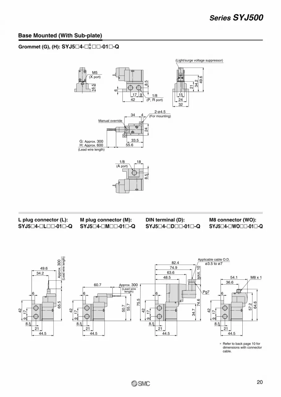
Series SYJ500
Grommet (G), (H): SYJ5�4-�GH ��-01�-Q
Base Mounted (With Sub-plate)
L plug connector (L):
SYJ5�4-�L��-01�-QM plug connector (M):
SYJ5�4-�M��-01�-Q
DIN terminal (D):
SYJ5�4-�D��-01�-Q
M8 connector (WO):
SYJ5�4-�WO��-01�-Q
55.6
21
32
24
15
18
16.5 8
.5
6
42
17 9
24
434
33.5
8.5
34.2 49.6
G: Approx. 300H: Approx. 600
(Lead wire length)
1/8(A port)
1/8(P, R port)
X
A
PR
M5(X port)
(Light/surge voltage suppressor)
Manual override
2-ø4.5(For mounting)
+-
60.7
MA
X. 10
74.6
82.4
74.9
63.6
54.1
36.6
57.2
64.6
21
8.5
6
42
17
9
21
8.5
6
42
17
9
21
8.5
6
42
17
9
21
8.5
6
42
17
9
∗ Refer to back page 10 for dimensions with connector cable.
M8 x 1
Pg7
Applicable cable O.D.
ø3.5 to ø7
48.5
34.7
75.5
44.5 44.5
Appro
x. 300
(Le
ad
wire
len
gth
)
65.5
55.7
50.7
44.5
49.6
34.2
44.5
Approx. 300 (Lead wire
length)
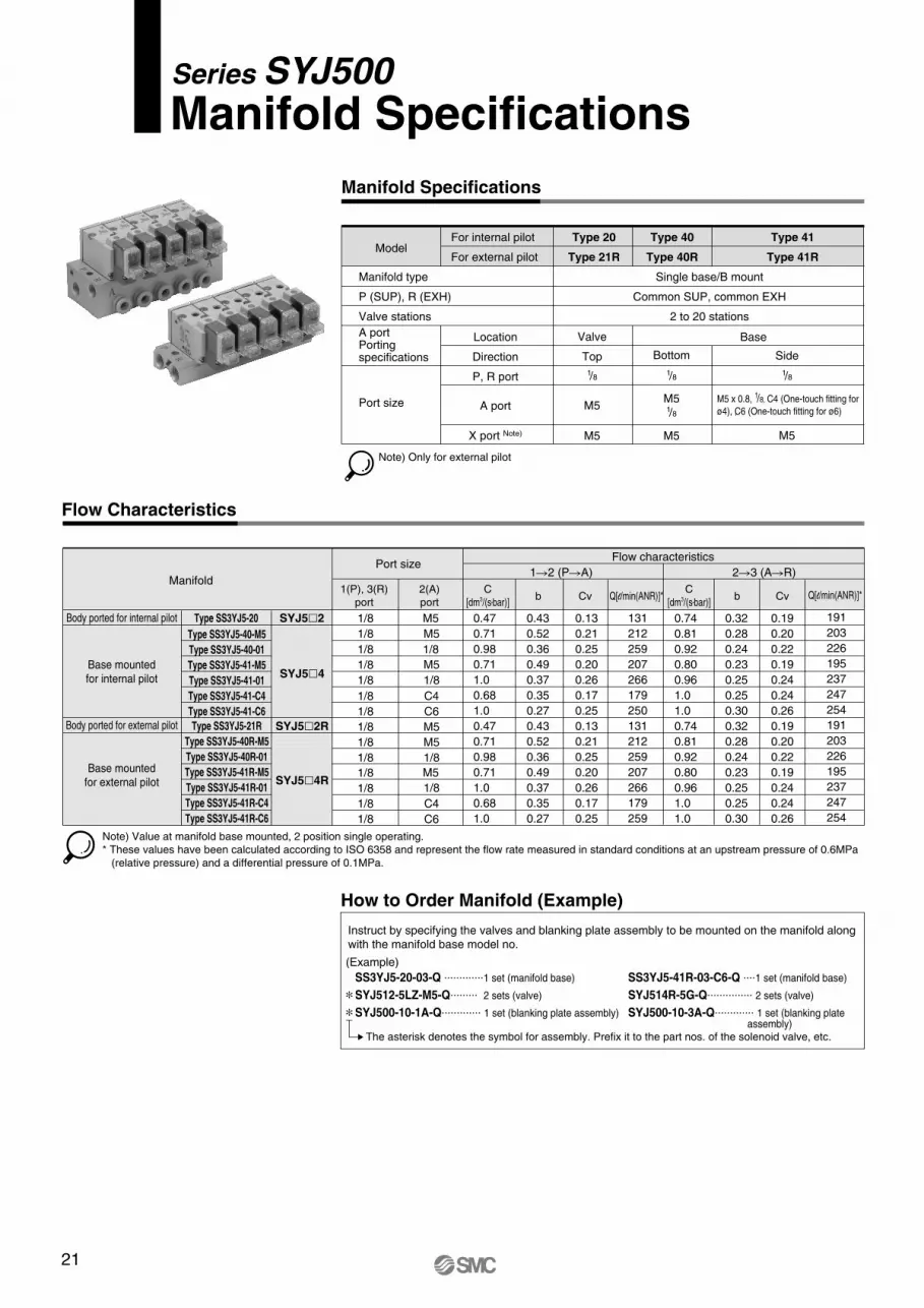
Manifold Specifications
Manifold SpecificationsSeries SYJ500
Model
Manifold type
P (SUP), R (EXH)
Valve stations
A portPorting specifications
Port size
For internal pilot
For external pilot
Type 20
Type 21R
Type 40
Type 40R
Type 41
Type 41R
Location
Direction
P, R port
A port
X port Note)
Valve
Top
M5
M5
M51/8
Single base/B mount
Common SUP, common EXH
2 to 20 stations
Base
1/8
M5
M5 x 0.8, 1/8, C4 (One-touch fitting for
ø4), , C6 (One-touch fitting for ø6)
Note) Only for external pilot
Bottom
1/8 1/8
M5
Side
Note) Value at manifold base mounted, 2 position single operating.
* These values have been calculated according to ISO 6358 and represent the flow rate measured in standard conditions at an upstream pressure of 0.6MPa
(relative pressure) and a differential pressure of 0.1MPa.
Type SS3YJ5-20
Type SS3YJ5-40-M5
Type SS3YJ5-40-01
Type SS3YJ5-41-M5
Type SS3YJ5-41-01
Type SS3YJ5-41-C4
Type SS3YJ5-41-C6
Type SS3YJ5-40R-M5
Type SS3YJ5-40R-01
Type SS3YJ5-41R-M5
Type SS3YJ5-41R-01
Type SS3YJ5-41R-C4
Type SS3YJ5-41R-C6
Type SS3YJ5-21R
C
[dm3/(s•bar)]
1(P), 3(R)
port
2(A)
portb Cv
C
[dm3/(s•bar)]b Cv
1�2 (P�A) 2�3 (A�R)Manifold
Flow characteristicsPort size
M5 0.47
0.71
0.98
0.71
1.0
0.68
1.0
0.47
0.71
0.98
0.71
1.0
0.68
1.0
0.43
0.52
0.36
0.49
0.37
0.35
0.27
0.43
0.52
0.36
0.49
0.37
0.35
0.27
0.13
0.21
0.25
0.20
0.26
0.17
0.25
0.13
0.21
0.25
0.20
0.26
0.17
0.25
0.74
0.81
0.92
0.80
0.96
1.0
1.0
0.74
0.81
0.92
0.80
0.96
1.0
1.0
0.32
0.28
0.24
0.23
0.25
0.25
0.30
0.32
0.28
0.24
0.23
0.25
0.25
0.30
0.19
0.20
0.22
0.19
0.24
0.24
0.26
0.19
0.20
0.22
0.19
0.24
0.24
0.26
M5
1/8
1/8
1/8 1/8
1/8
C41/8
1/8
M5
M5
1/8
1/8
C61/8
M51/8
M51/8
1/8
C4
C6
1/8
1/8
1/8
1/8
1/8
SYJ5�2
SYJ5�4
SYJ5�2R
SYJ5�4R
Body ported for internal pilot
Body ported for external pilot
Base mounted
for internal pilot
Base mounted
for external pilot
Flow Characteristics
Q[l/min(ANR)]*
131
212
259
207
266
179
250
131
212
259
207
266
179
259
Q[l/min(ANR)]*
191
203
226
195
237
247
254
191
203
226
195
237
247
254
How to Order Manifold (Example)
Instruct by specifying the valves and blanking plate assembly to be mounted on the manifold along
with the manifold base model no.
(Example)
SS3YJ5-20-03-Q .............1 set (manifold base)
SYJ512-5LZ-M5-Q......... 2 sets (valve)
SYJ500-10-1A-Q............. 1 set (blanking plate assembly)
SS3YJ5-41R-03-C6-Q ....1 set (manifold base)
SYJ514R-5G-Q............... 2 sets (valve)
SYJ500-10-3A-Q............. 1 set (blanking plate assembly)
The asterisk denotes the symbol for assembly. Prefix it to the part nos. of the solenoid valve, etc.
∗∗
21
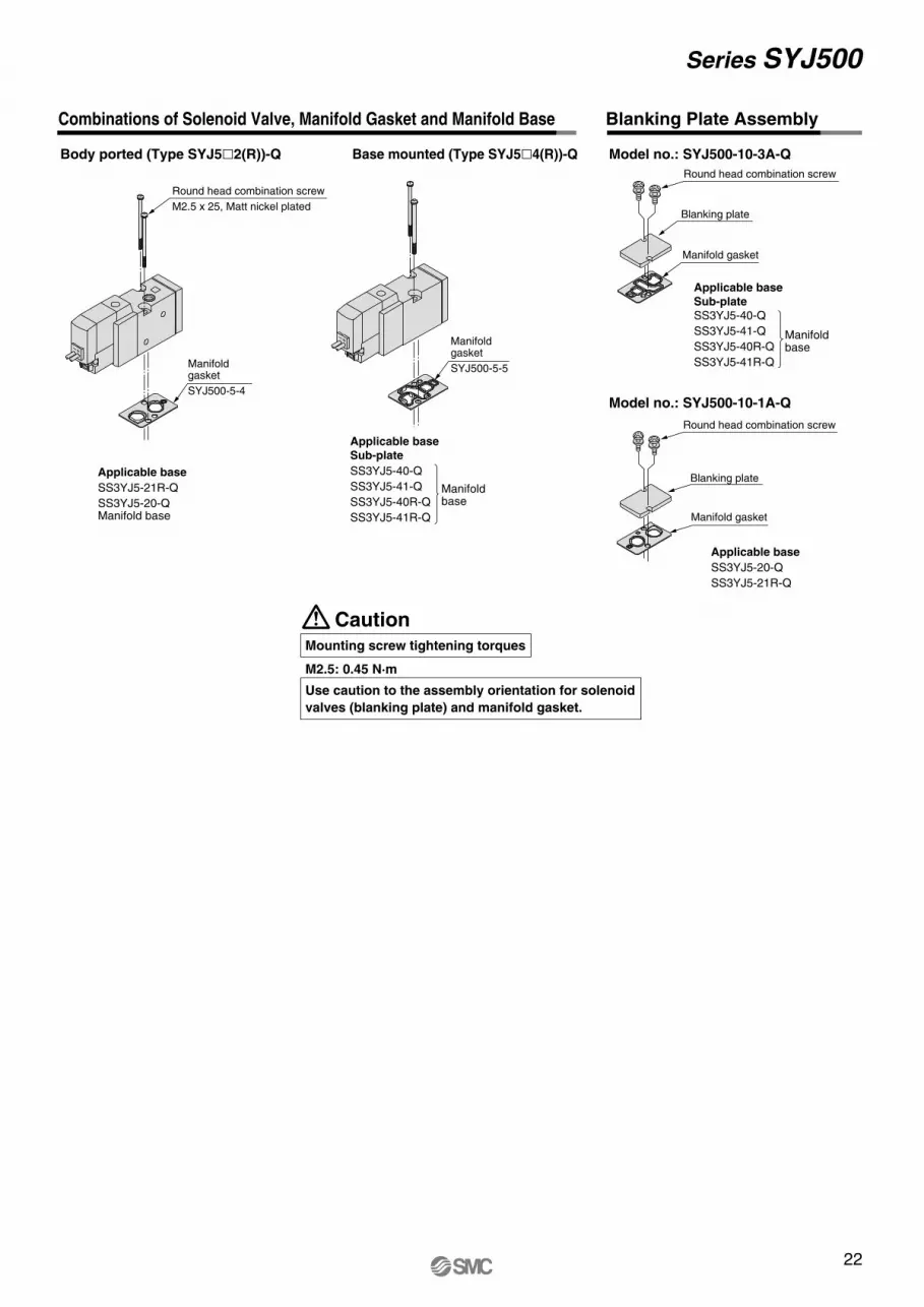
Body ported (Type SYJ5�2(R))-Q Base mounted (Type SYJ5�4(R))-Q Model no.: SYJ500-10-3A-Q
Model no.: SYJ500-10-1A-Q
Applicable base Sub-plate
SS3YJ5-40-Q
SS3YJ5-41-Q
SS3YJ5-40R-Q
SS3YJ5-41R-Q
Manifoldbase
Manifold gasket
SYJ500-5-5
Combinations of Solenoid Valve, Manifold Gasket and Manifold Base Blanking Plate Assembly
Applicable base
SS3YJ5-21R-Q
SS3YJ5-20-QManifold base
Manifold gasket
SYJ500-5-4
Round head combination screw
M2.5 x 25, Matt nickel plated
Applicable base Sub-plate SS3YJ5-40-Q
SS3YJ5-41-Q
SS3YJ5-40R-Q
SS3YJ5-41R-Q
Manifoldbase
Manifold gasket
Round head combination screw
Blanking plate
Applicable base
SS3YJ5-20-Q
SS3YJ5-21R-Q
Manifold gasket
Round head combination screw
Blanking plate
Series SYJ500
–+
–+
CautionMounting screw tightening torques
M2.5: 0.45 N·m
Use caution to the assembly orientation for solenoid
valves (blanking plate) and manifold gasket.
22
–+
–+
–+
–+
A
X
PR
–+
–+
–+
–+X
PR
A
A
A
A
23
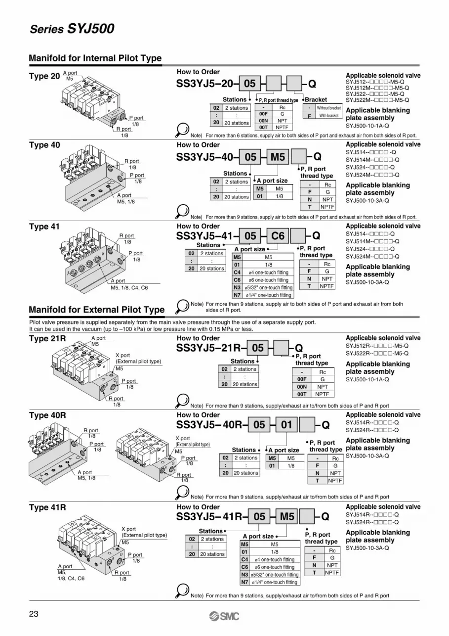
Series SYJ500
Type 20
Type 40
Type 41
Type 21R
Type 40R
Note) For more than 9 stations, supply/exhaust air to/from both sides of P and R port
How to OrderApplicable solenoid valveSYJ512--����-M5-QSYJ512M--����-M5-QSYJ522--����-M5-QSYJ522M--����-M5-Q
Applicable blankingplate assemblySYJ500-10-1A-Q
Applicable solenoid valveSYJ514--���� -Q
SYJ514M--����-Q
SYJ524--����-Q
SYJ524M--����-Q
Applicable blankingplate assemblySYJ500-10-3A-Q
Applicable solenoid valveSYJ514--����-Q
SYJ514M--����-Q
SYJ524--����-Q
SYJ524M--����-Q
Applicable blankingplate assemblySYJ500-10-3A-Q
Applicable solenoid valveSYJ512R--����-M5-Q
SYJ522R--����-M5-Q
Applicable blankingplate assemblySYJ500-10-1A-Q
Applicable solenoid valveSYJ514R--����-Q
SYJ524R--����-Q
Applicable blankingplate assemblySYJ500-10-3A-Q
Note) For more than 9 stations, supply air to both sides of P port and exhaust air from both sides of R port.
Note) For more than 6 stations, supply air to both sides of P port and exhaust air from both sides of R port.
SS3YJ5--20-- 05 --
Note) For more than 9 stations, supply air to both sides of P port and exhaust air from both sides of R port.
Note) For more than 9 stations, supply/exhaust air to/from both sides of P and R port
How to Order
SS3YJ5--40-- 05 -- M5
02
:
20
2 stations
:
20 stations
Stations
How to Order
SS3YJ5-- 40R-- 05 -- 01
02
:
20
2 stations
:
20 stations
Stations
02
:
20
2 stations
:
20 stations
Stations
M5
01
M5
1/8
A port size
How to Order
SS3YJ5--21R-- 05 --
02
:
20
2 stations
:
20 stations
Stations
How to Order
SS3YJ5--41-- 05 -- C6
02
:
20
2 stations
:
20 stations
Stations
M5
01
C4
C6
N3
N7
M5
1/8
ø4 one-touch fitting
ø6 one-touch fitting
ø5/32" one-touch fitting
ø1/4" one-touch fitting
A port size
Pilot valve pressure is supplied separately from the main valve pressure through the use of a separate supply port.
It can be used in the vacuum (up to –100 kPa) or low pressure line with 0.15 MPa or less.
Manifold for Internal Pilot Type
Manifold for External Pilot Type
M5
01
M5
1/8
A port size
-
F
Without bracket
With bracket
Bracket
Type 41R
Note) For more than 9 stations, supply/exhaust air to/from both sides of P and R port
Applicable solenoid valveSYJ514R--����-Q
SYJ524R--����-Q
Applicable blankingplate assemblySYJ500-10-3A-Q
How to Order
SS3YJ5-- 41R-- 05 -- M5
02
:
20
2 stations
:
20 stations
Stations
M5
01
C4
C6
N3
N7
M5
1/8
ø4 one-touch fitting
ø6 one-touch fitting
ø5/32" one-touch fitting
ø1/4" one-touch fitting
A port size
R port
1/8
1/8P port
A portM5
R port 1/8
P port 1/8
A port
M5, 1/8, C4, C6
P port 1/8
M5
X port(External pilot type)
R port 1/8
A portM5
M5
X port(External pilot type)
A portM5, 1/8
R port 1/8
P port 1/8
P port 1/8
R port 1/8
P port 1/8
M5
X port(External pilot type)
R port
1/8
A portM5, 1/8, C4, C6
Rc
G
NPT
NPTF
P, R port thread type
00F
00N
00T
-
Rc
G
NPT
NPTF
P, R portthread type
00F
00N
00T
-
Rc
G
NPT
NPTF
P, R portthread type
F
N
T
-
Rc
G
NPT
NPTF
P, R portthread type
F
N
T
-
Rc
G
NPT
NPTF
P, R portthread type
F
N
T
-
Rc
G
NPT
NPTF
P, R portthread type
F
N
T
-
–+
–+
–+
–+R
P
R port 1/8
P port 1/8
A port
M5, 1/8
–+
–+
–+
–+X
PR
A
A
R
P
Q
Q
Q
Q
Q
Q
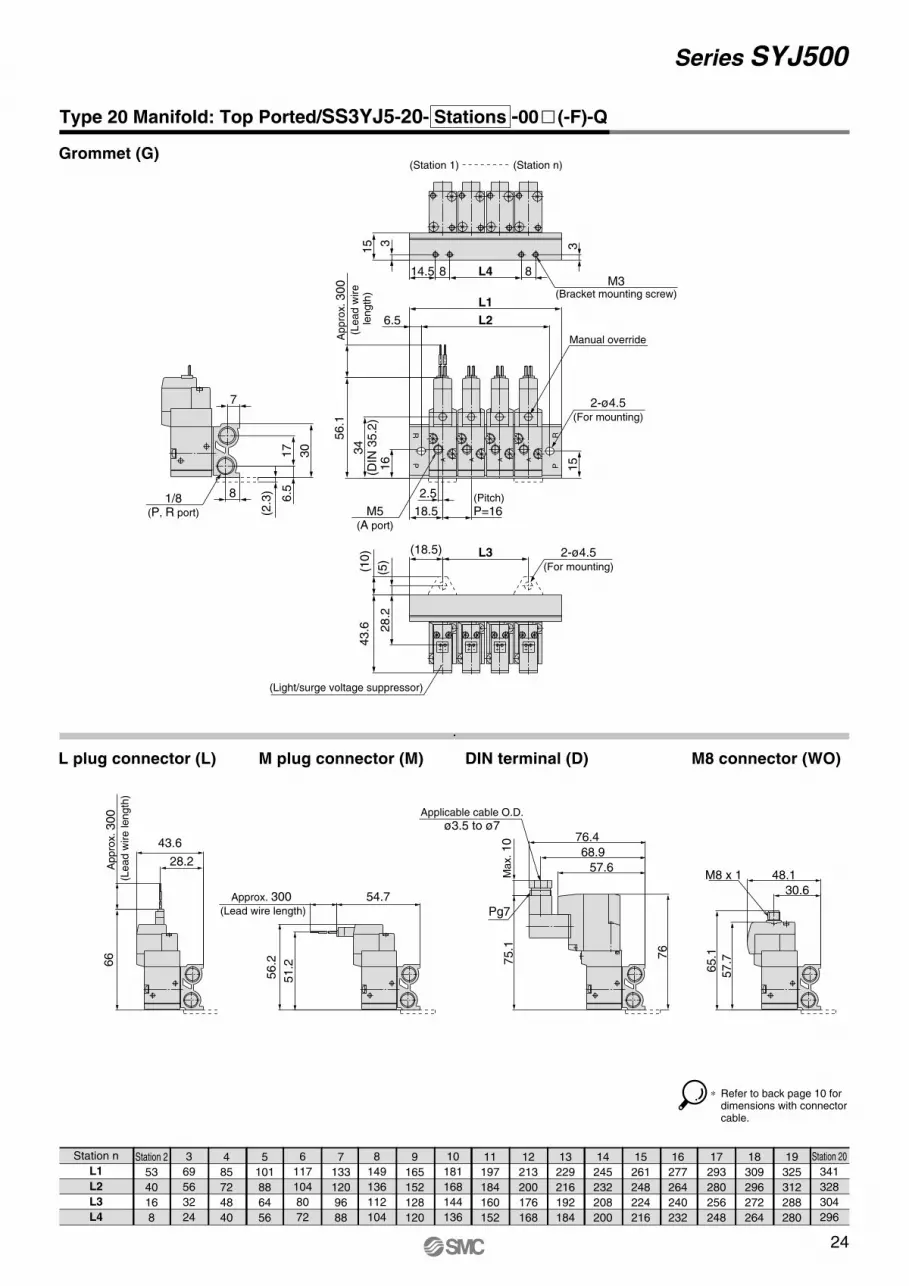
24
Series SYJ500
Station n
L1
L2
L3
L4
Station 2
53
40
16
8
3
69
56
32
24
4
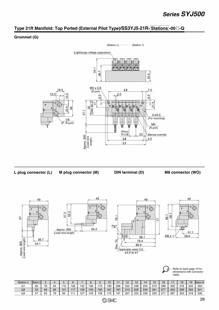
85
72
48
40
5
101
88
64
56
6
117
104
80
72
7
133
120
96
88
8
149
136
112
104
9
165
152
128
120
10
181
168
144
136
11
197
184
160
152
12
213
200
176
168
13
229
216
192
184
14
245
232
208
200
15
261
248
224
216
16
277
264
240
232
17
293
280
256
248
18
309
296
272
264
19
325
312
288
280
Station 20
341
328
304
296
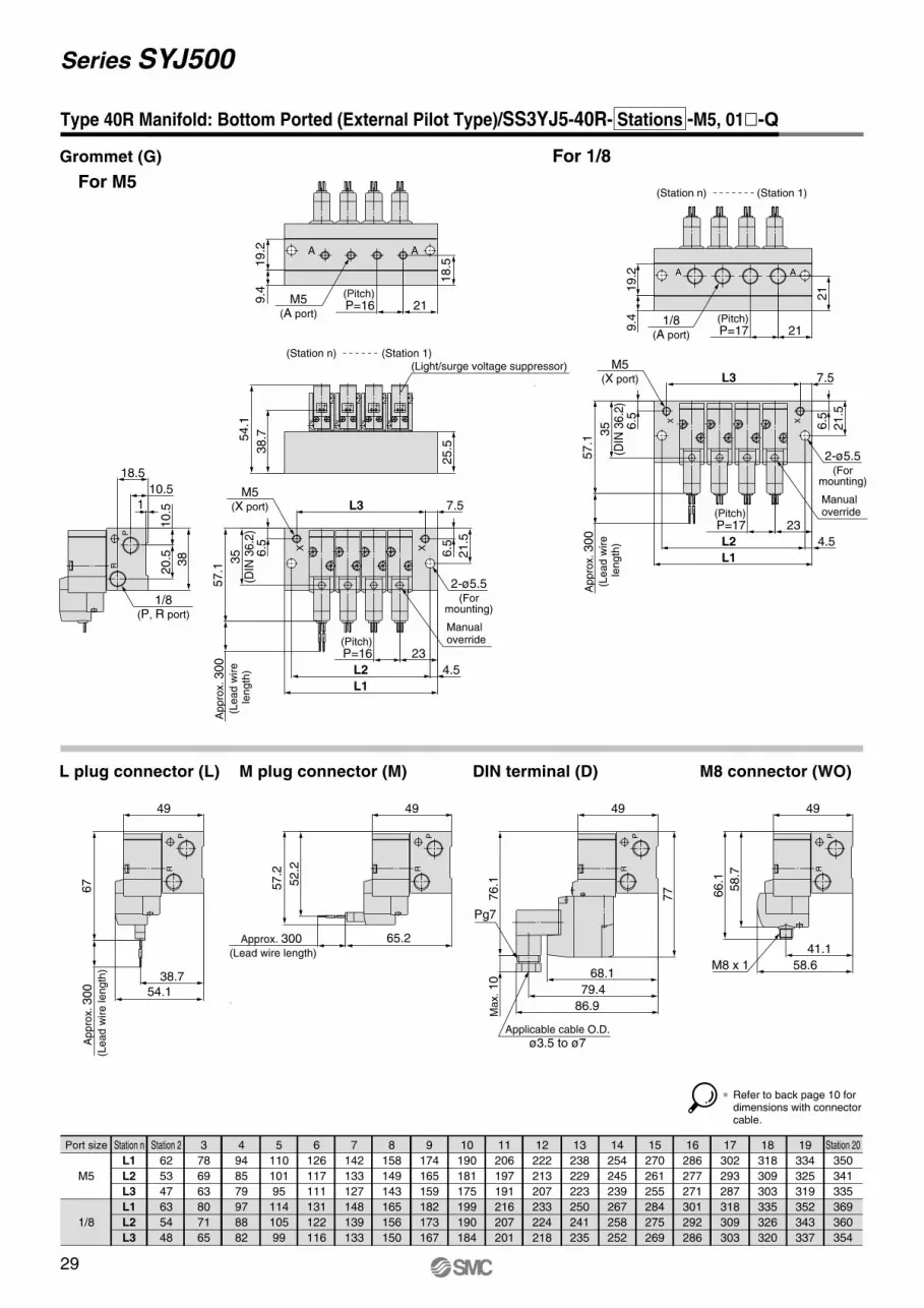
Type 20 Manifold: Top Ported/SS3YJ5-20- Stations -00� (-F)-Q
Grommet (G)
L plug connector (L) M plug connector (M) DIN terminal (D) M8 connector (WO)
(18.5) L3
(10)
(5)
43.6 2
8.2
2-ø4.5(For mounting)
(Light/surge voltage suppressor)
+ - + - + -+ -
56.1
6.5
15
L1
L2
34
(DIN
35.2
)
Appro
x. 300
(Lead w
ire
length
)
16
2.5 (Pitch)
P=1618.5
PR
PR
2-ø4.5(For mounting)
M5(A port)
Manual override
A A AA
30
(2.3
)
7
17
6.581/8
(P, R port)
14.5 L4 88
315 3
M3(Bracket mounting screw)
(Station n)(Station 1)
Appro
x. 300
(Lead w
ire length
)
66
43.6
28.2
54.7Approx. 300 (Lead wire length)
56.2
51.2
Max. 10
75.1
57.6
76.4
68.9
Applicable cable O.D.
ø3.5 to ø7
Pg7
76
48.1
30.6
65.1
57.7
M8 x 1
∗ Refer to back page 10 for dimensions with connector cable.
25
Series SYJ500
Station n
L1
L2
L1
L2
Station 2
52
43
63
54
3
68
59
80
71
4
84
75
97
88
5
100
91
114
105
6
116
107
131
122
7
132
123
148
139
8
148
139
165
156
9
164
155
182
173
10
180
171
199
190
11
196
187
216
207
12
212
203
233
224
13
228
219
250
241
14
244
235
267
258
15
260
251
284
275
16
276
267
301
292
17
292
283
318
309
18
308
299
335
326
19
324
315
352
343
Station 20
340
331
369
360
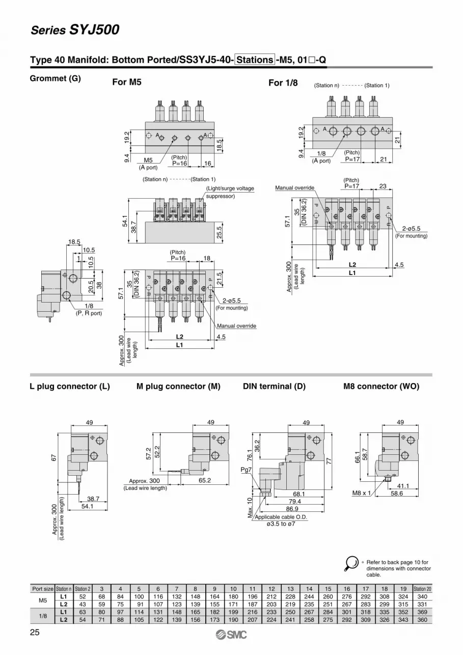
Port size
M5
1/8
Type 40 Manifold: Bottom Ported/SS3YJ5-40- Stations -M5, 01�-Q
Grommet (G) For M5
L plug connector (L) M plug connector (M)
For 1/8
DIN terminal (D) M8 connector (WO)
57.1
4.5
L1
L2
21.5
Manual override
Ap
pro
x. 300
(Le
ad
wire
le
ng
th)
35
(DIN
36
.2)
PR
RP
(Pitch)P=16 18
2-ø5.5(For mounting)
1
18.5
10.5
38
20.5
10.5
1/8(P, R port)
57.1
4.5
L1
L2
35
(DIN
36
.2)
Ap
pro
x. 300
(Le
ad
wire
le
ng
th)
2-ø5.5(For mounting)
(Pitch)P=17 23
RP
PR
Manual override
21
(Pitch)
P=17 21
19.2
9.4 1/8
(A port)
A A
25.5
54.1
38.7
(Station n) (Station 1)
(Light/surge voltage
suppressor)
+-+-+-+-
19.2
9.4 (Pitch)
P=16 16
18.5
AA
M5(A port)
49
Ap
pro
x. 300
(Le
ad
wire
le
ng
th)
67
54.138.7
65.2
49
Approx. 300 (Lead wire length)
57.2
52.2
76.1
Ma
x. 10
68.1
86.979.4
Applicable cable O.D.
ø3.5 to ø7
Pg7
77
49
36.2
66.1
58.7
58.641.1
M8 x 1
49
∗ Refer to back page 10 for dimensions with connector cable.
(Station n) (Station 1)
26
Series SYJ500
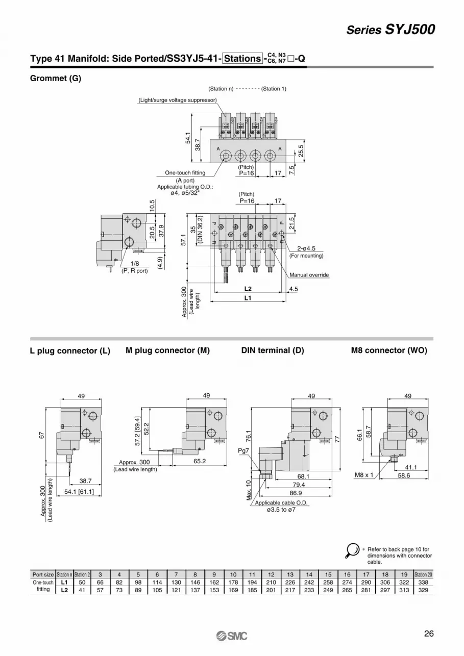
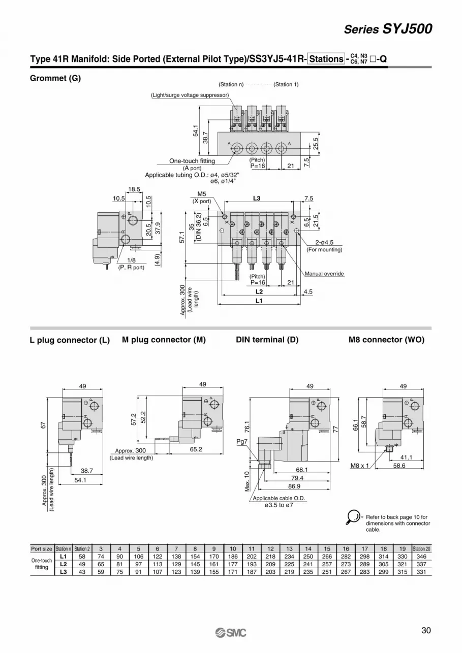
Type 41 Manifold: Side Ported/SS3YJ5-41- Stations - �-Q
Grommet (G)
L plug connector (L) M plug connector (M) DIN terminal (D) M8 connector (WO)
Station n
L1
L2
Station 2
50
41
3
66
57
4
82
73
5
98
89
6
114
105
7
130
121
8
146
137
9
162
153
10
178
169
11
194
185
12
210
201
13
226
217
14
242
233
15
258
249
16
274
265
17
290
281
18
306
297
19
322
313
Station 20
338
329
Port size
One-touch
fitting
∗ Refer to back page 10 for dimensions with connector cable.
57.1
L2
Appro
x. 300
(Lead w
ire
length
)35
(DIN
36.2
)
21.5
4.5
L1
(Pitch)
P=16 17
RP
RP
2-ø4.5(For mounting)
Manual override
37.9
20.5
10.5
(4.9
)
1/8(P, R port)
25.5
54.1
38.7
7.5(Pitch)
P=16 17One-touch fitting
(A port)Applicable tubing O.D.:
ø4, ø5/32"
(Station 1)(Station n)
A A
(Light/surge voltage suppressor)
+- +- +- +-
49
Appro
x. 300
(Lead w
ire length
)
67
54.1 [61.1]
38.7
65.2
49
Approx. 300 (Lead wire length)
57.2
[59.4
]
52.2
76.1
Max. 10
68.1
86.9
79.4
Applicable cable O.D.
ø3.5 to ø7
Pg7
77
49
41.1
58.6
66.1
58.7
M8 x 1
49
C4, N3C6, N7
27
Series SYJ500
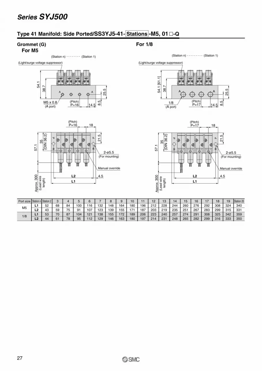
Type 41 Manifold: Side Ported/SS3YJ5-41- Stations -M5, 01�-Q
Station 2
52
43
53
44
Station n
L1
L2
L1
L2
3
68
59
70
61
4
84
75
87
78
5
100
91
104
95
6
116
107
121
112
7
132
123
138
129
8
148
139
155
146
9
164
155
172
163
10
180
171
189
180
11
196
187
206
197
12
212
203
223
214
13
228
219
240
231
14
244
235
257
248
15
260
251
274
265
16
276
267
291
282
17
292
283
308
299
18
308
299
325
316
19
324
315
342
333
Station 20
340
331
359
350
Port size
M5
1/8
For 1/8Grommet (G)
For M5
57.1
35
(DIN
36.2
)
Ap
pro
x. 300
(Le
ad
wire
le
ng
th)
Manual override
4.5
L1
L2
(Pitch)P=16 18
21.5P
R
PR
2-ø5.5(For mounting)
M5 x 0.8(A port)
(Pitch)P=16 14.5
25.5
8.5
54.1
38.7
(Station 1)(Station n)
A A
(Light/surge voltage suppressor)
+-+-+-+-
57.1
35
(DIN
36.2
)
Ap
pro
x. 300
(Le
ad
wire
le
ng
th)
Manual override
21.5
(Pitch)P=17 18
4.5
L1
L2
PR
PR
(Station 1)(Station n)
2-ø5.5(For mounting)
AA
8.5
25.5
(Pitch)P=17 14.5
38.7
54.1
[61.1
]
1/8(A port)
(Light/surge voltage suppressor)
+- +- +- +-
28
Series SYJ500
Station n
L1
L2
L3
Station 2
62
53
47
3
78
69
63
4
94
85
79
5
110
101
95
6
126
117
111
7
142
133
127
8
158
149
143
9
174
165
159
10
190
181
175
11
206
197
191
12
222
213
207
13
238
229
223
14
254
245
239
15
270
261
255
16
286
277
271
17
302
293
287
18
318
309
303
19
334
325
319
Station 20
350
341
335
L plug connector (L) M plug connector (M)
Type 21R Manifold: Top Ported (External Pilot Type)/SS3YJ5-21R- Stations -00�-Q
Grommet (G)
DIN terminal (D) M8 connector (WO)
∗ Refer to back page 10 for dimensions with connector cable.
A A A A57.1
4.5
L1
L2
21.5
6.5
L3 7.5
6.5
2.517
(Pitch)P=16 23
Ap
pro
x. 300
(Le
ad
wire
le
ng
th)
35
(DIN
36.2
)
M5 x 0.8(X port)
XX
2-ø5.5(For mounting)
M5(A port)
Manual override
18.5
10.5
20.5 38
10.5
P
R
1/8(P, R port)
+- +- +- +-
25.5
54.1
38.7
(Station 1)(Station n)
(Light/surge voltage suppressor)
49
Ap
pro
x. 300
(Le
ad
wire
le
ng
th)
67
38.7
54.1
P
R
65.2
49
Approx. 300 (Lead wire length)
57.2
52.2
PR
76.1
Ma
x. 10
68.1
79.4
86.9
P
R
Applicable cable O.D.
ø3.5 to ø7
Pg7
77
49
41.1
58.6
58.7
66.1
M8 x 1
P
R
49
Series SYJ500
3
78
69
63
80
71
65
Station n
L1
L2
L3
L1
L2
L3
Station 2
62
53
47
63
54
48
4
94
85
79
97
88
82
5
110
101
95
114
105
99
6
126
117
111
131
122
116
7
142
133
127
148
139
133
8
158
149
143
165
156
150
9
174
165
159
182
173
167
10
190
181
175
199
190
184
11
206
197
191
216
207
201
12
222
213
207
233
224
218
13
238
229
223
250
241
235
14
254
245
239
267
258
252
15
270
261
255
284
275
269
16
286
277
271
301
292
286
17
302
293
287
318
309
303
18
318
309
303
335
326
320
19
334
325
319
352
343
337
Station 20
350
341
335
369
360
354
Port size
M5
1/8
Type 40R Manifold: Bottom Ported (External Pilot Type)/SS3YJ5-40R- Stations -M5, 01�-Q
Grommet (G)
For M5
L plug connector (L) M plug connector (M)
For 1/8
DIN terminal (D) M8 connector (WO)
57.1
L3 7.5
21.5
6.5
L1
L2 4.5
6.5
23(Pitch)P=16
M5(X port)
35
(DIN
36.2
)
Ap
pro
x. 300
(Le
ad
wire
le
ng
th)
Manualoverride
XX
2-ø5.5(For
mounting)
1
38
20.5
10.5
18.5
10.5
P
R
1/8(P, R port)
57.1
L3 7.5
4.5
L1
L2
21.5
6.5
6.5
23(Pitch)P=17
M5(X port)
35
(DIN
36.2
)
Ap
pro
x. 300
(Le
ad
wire
le
ng
th)
Manualoverride
2-ø5.5(For
mounting)
X X
21
(Pitch)P=17 21
19.2
9.4 1/8
(A port)
A A
25.5
54.1
38.7
(Station n) (Station 1)(Light/surge voltage suppressor)
+-+-+-+-
19.2
9.4
18.5
(Pitch)P=16 21
AA
M5(A port)
49
Ap
pro
x. 300
(Le
ad
wire
le
ng
th)
67
54.1
38.7
P
R
65.2
49
Approx. 300 (Lead wire length)
57.2
52.2
P
R
68.1
79.4
86.9
76.1
Ma
x. 10
P
R
Applicable cable O.D.
ø3.5 to ø7
Pg7
77
49
66.1
58.7
58.6
41.1
M8 x 1
P
R49
29
(Station n) (Station 1)
∗ Refer to back page 10 for dimensions with connector cable.
30
Series SYJ500
3
74
65
59
Station n
L1
L2
L3
Station 2
58
49
43
4
90
81
75
5
106
97
91
6
122
113
107
7
138
129
123
8
154
145
139
9
170
161
155
10
186
177
171
11
202
193
187
12
218
209
203
13
234
225
219
14
250
241
235
15
266
257
251
16
282
273
267
17
298
289
283
18
314
305
299
19
330
321
315
Station 20
346
337
331
Type 41R Manifold: Side Ported (External Pilot Type)/SS3YJ5-41R- Stations - �-Q
Grommet (G)
L plug connector (L) M plug connector (M)
Port size
One-touch
fitting
DIN terminal (D) M8 connector (WO)
∗ Refer to back page 10 for dimensions with connector cable.
C4, N3C6, N7
57.1
4.5L2
L1
6.5
L3 7.5
21.5
6.5
M5(X port)
21(Pitch)P=16
35
(DIN
36.2
)
Ap
pro
x. 300
(Le
ad
wire
le
ng
th)
Manual override
XX
2-ø4.5(For mounting)
20.5
10.5
37.9
18.5
10.5
(4.9
)
P
R
1/8(P, R port)
25.5
(Pitch)P=16 21 7
.5
54.1
38.7
One-touch fitting(A port)
Applicable tubing O.D.: ø4, ø5/32"
(Station n) (Station 1)
(Light/surge voltage suppressor)
+- +- +- +-
49
Ap
pro
x. 300
(Le
ad
wire
le
ng
th)
67
54.1
38.7
P
R
65.2
49
Approx. 300 (Lead wire length)
57.2
52.2
P
R
76.1
Ma
x. 10
68.1
79.4
86.9
P
R
Applicable cable O.D.
ø3.5 to ø7
Pg7
77
49
41.1
58.6
66.1
58.7
M8 x 1
P
R
49
ø6, ø1/4"
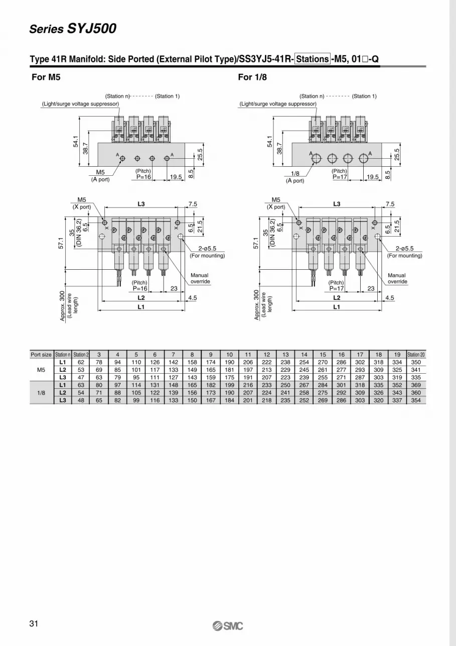
31
Series SYJ500
Station n
L1
L2
L3
L1
L2
L3
Station 2
62
53
47
63
54
48
3
78
69
63
80
71
65
4
94
85
79
97
88
82
5
110
101
95
114
105
99
6
126
117
111
131
122
116
7
142
133
127
148
139
133
8
158
149
143
165
156
150
9
174
165
159
182
173
167
10
190
181
175
199
190
184
11
206
197
191
216
207
201
12
222
213
207
233
224
218
13
238
229
223
250
241
235
14
254
245
239
267
258
252
15
270
261
255
284
275
269
16
286
277
271
301
292
286
17
302
293
287
318
309
303
18
318
309
303
335
326
320
19
334
325
319
352
343
337
Station 20
350
341
335
369
360
354
Type 41R Manifold: Side Ported (External Pilot Type)/SS3YJ5-41R- Stations -M5, 01�-Q
For M5 For 1/8
Port size
M5
1/8
57.1
(Pitch)P=16 23
4.5
L1
L2
35
(DIN
36.2
)6.5
21.5
6.5
L3 7.5M5
(X port)
Ap
pro
x. 300
(Le
ad
wire
le
ng
th)
XX
Manual override
2-ø5.5(For mounting)
(Pitch)P=16 19.5
25.5
8.5
54.1
38.7
M5(A port)
(Station 1)(Station n)
A A
(Light/surge voltage suppressor)
+-+-+-+-
57.1
35
(DIN
36.2
)
Ap
pro
x. 300
(Le
ad
wire
le
ng
th)
6.5
6.5
M5(X port)
Manual override
2-ø5.5(For mounting)
23(Pitch)P=17
4.5L2
L1
L3 7.5
21.5
X X
19.5(Pitch)P=17
25.5
8.5
54.1
38.7
AA
(Station 1)(Station n)
(Light/surge voltage suppressor)
1/8(A port)
+- +- +- +-

32
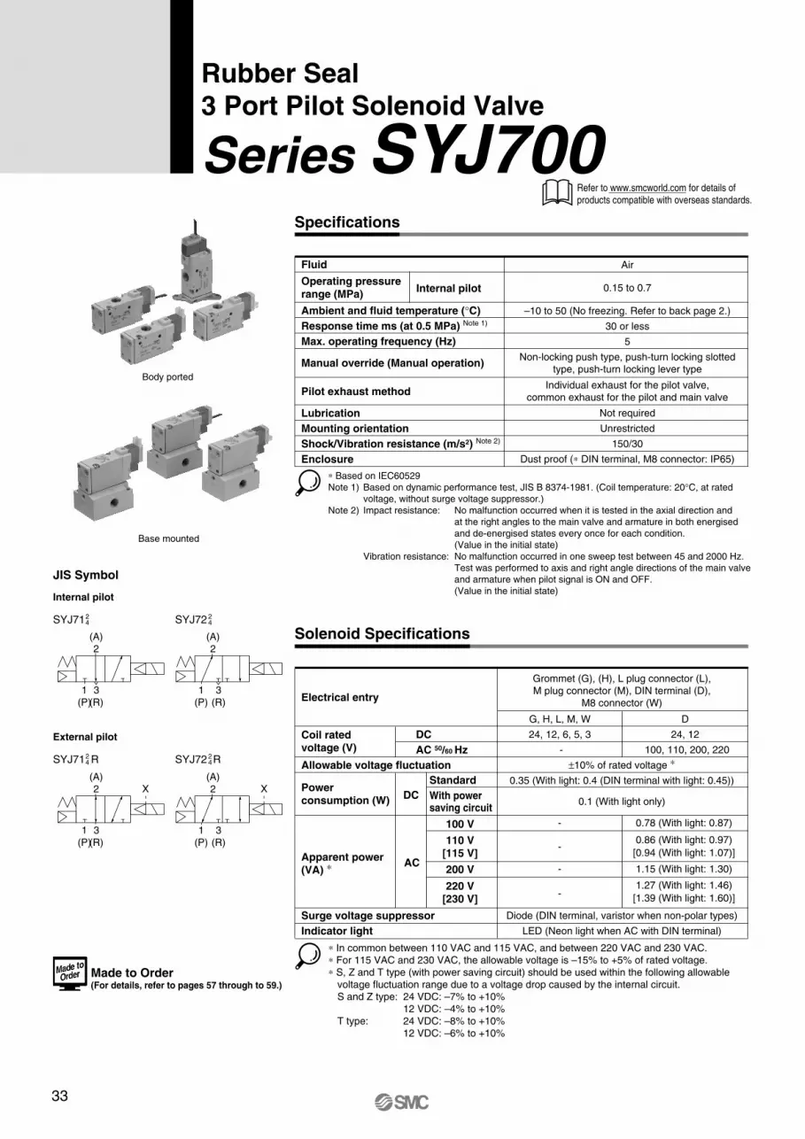
33
JIS Symbol
Internal pilot
SYJ7124 SYJ72 2
4
External pilot
SYJ71 R24 SYJ72 R2
4
X X
(A)
2
1
(P)
3
(R)
(A)
2
1
(P)
3
(R)
(A)
2
1
(P)
3
(R)
(A)
2
1
(P)
3
(R)
Body ported
Base mounted
Series SYJ700
Rubber Seal3 Port Pilot Solenoid Valve
Solenoid Specifications
Specifications
Fluid
Operating pressure range (MPa)
Ambient and fluid temperature (°C)
Response time ms (at 0.5 MPa) Note 1)
Max. operating frequency (Hz)
Manual override (Manual operation)
Pilot exhaust method
Lubrication
Mounting orientation
Shock/Vibration resistance (m/s2) Note 2)
Enclosure
Internal pilot
–10 to 50 (No freezing. Refer to back page 2.)
30 or less
5
Non-locking push type, push-turn locking slotted
type, push-turn locking lever type
Air
0.15 to 0.7
Not required
Unrestricted
150/30
Dust proof (∗ DIN terminal, M8 connector: IP65)
Individual exhaust for the pilot valve,
common exhaust for the pilot and main valve
∗ Based on IEC60529
Note 1) Based on dynamic performance test, JIS B 8374-1981. (Coil temperature: 20°C, at rated
voltage, without surge voltage suppressor.)
Note 2) Impact resistance: No malfunction occurred when it is tested in the axial direction and
at the right angles to the main valve and armature in both energised
and de-energised states every once for each condition.
(Value in the initial state)
Vibration resistance: No malfunction occurred in one sweep test between 45 and 2000 Hz.
Test was performed to axis and right angle directions of the main valve
and armature when pilot signal is ON and OFF.
(Value in the initial state)
Refer to www.smcworld.com for details of
products compatible with overseas standards.
Made to Order(For details, refer to pages 57 through to 59.)
Electrical entry
Coil rated voltage (V)
DC
AC 50/60 Hz
Standard
With powersaving circuit
Surge voltage suppressor
Indicator light
Power consumption (W)
DC
Apparent power(VA) ∗
AC
100 V
110 V[115 V]
200 V
220 V[230 V]
- 100, 110, 200, 220
±10% of rated voltage ∗
0.35 (With light: 0.4 (DIN terminal with light: 0.45))
0.1 (With light only)
-
-
-
-
0.78 (With light: 0.87)
1.15 (With light: 1.30)
0.86 (With light: 0.97)
[0.94 (With light: 1.07)]
1.27 (With light: 1.46)
[1.39 (With light: 1.60)]
Diode (DIN terminal, varistor when non-polar types)
LED (Neon light when AC with DIN terminal)
Grommet (G), (H), L plug connector (L),
M plug connector (M), DIN terminal (D),
M8 connector (W)
∗ In common between 110 VAC and 115 VAC, and between 220 VAC and 230 VAC.
∗ For 115 VAC and 230 VAC, the allowable voltage is –15% to +5% of rated voltage.
∗ S, Z and T type (with power saving circuit) should be used within the following allowable
voltage fluctuation range due to a voltage drop caused by the internal circuit.
S and Z type: 24 VDC: –7% to +10%
12 VDC: –4% to +10%
T type: 24 VDC: –8% to +10%
12 VDC: –6% to +10%
Allowable voltage fluctuation
G, H, L, M, W
24, 12, 6, 5, 3
D
24, 12
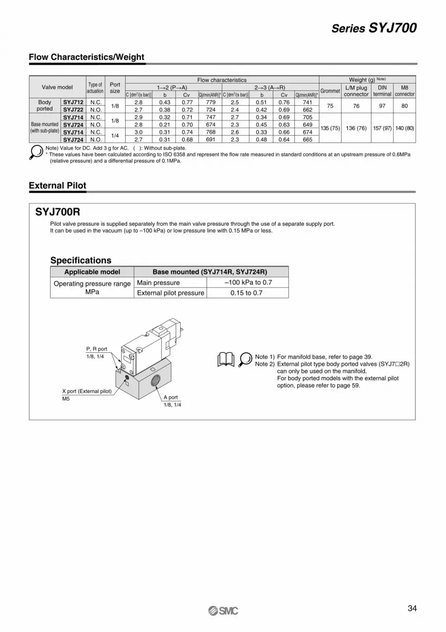
34
Series SYJ700
Flow Characteristics/Weight
External Pilot
SYJ700RPilot valve pressure is supplied separately from the main valve pressure through the use of a separate supply port.
It can be used in the vacuum (up to –100 kPa) or low pressure line with 0.15 MPa or less.
External pilot pressure
Main pressure
SpecificationsApplicable model
Operating pressure range
MPa
Base mounted (SYJ714R, SYJ724R)
Note 1) For manifold base, refer to page 39.Note 2) External pilot type body ported valves (SYJ7�2R)
can only be used on the manifold.For body ported models with the external pilot option, please refer to page 59.
–100 kPa to 0.7
0.15 to 0.7
P, R port
1/8, 1/4
A port
1/8, 1/4
X port (External pilot)
M5
Note) Value for DC. Add 3 g for AC. ( ): Without sub-plate.
* These values have been calculated according to ISO 6358 and represent the flow rate measured in standard conditions at an upstream pressure of 0.6MPa
(relative pressure) and a differential pressure of 0.1MPa.
SYJ712
SYJ722
SYJ714
SYJ724
SYJ714
SYJ724
C [dm3/(s bar)] b Cv C [dm3/(s bar)] b Cv
1�2 (P�A) 2�3 (A�R) Valve model
Flow characteristics Weight (g) Note)
GrommetL/M plugconnector
DINterminal
Type ofactuation
Portsize
1/8 75
135 (75)
76
136 (76)
97
157 (97)
M8connector
80
140 (80)
1/8
1/4
N.C. 2.8
2.7
2.9
2.8
3.0
2.7
0.43
0.38
0.32
0.21
0.31
0.31
0.77
0.72
0.71
0.70
0.74
0.68
2.5
2.4
2.7
2.3
2.6
2.3
0.51
0.42
0.34
0.45
0.33
0.48
0.76
0.69
0.69
0.63
0.66
0.64
N.O.
N.C.
N.O.
N.C.
N.O.
Bodyported
Base mounted(with sub-plate)
Q[l/min(ANR)]*
779
724
747
674
768
691
Q[l/min(ANR)]*
741
662
705
649
674
665
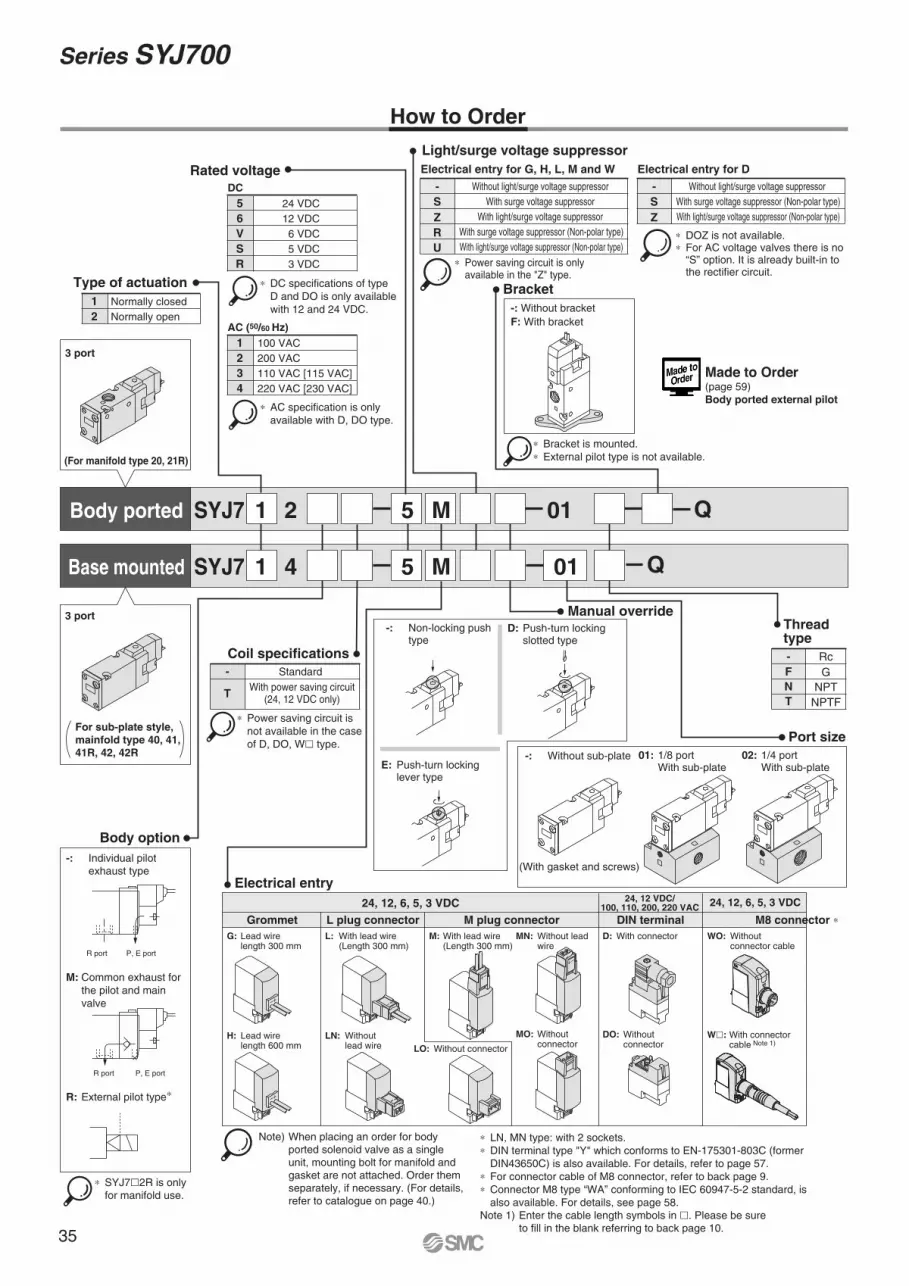
35
Series SYJ700
SYJ7 2 5 M 01
SYJ7 4 5 M 01
1
1
1
2
Normally closed
Normally open
Type of actuation
5
6
V
S
R
24 VDC
12 VDC
6 VDC
5 VDC
3 VDC
Rated voltage
DC
1
2
3
4
100 VAC
200 VAC
110 VAC [115 VAC]
220 VAC [230 VAC]
AC (50/60 Hz)
3 port
(For manifold type 20, 21R)
3 port
Body option
-: Individual pilot
exhaust type
M: Common exhaust for
the pilot and main
valve
R: External pilot type∗
∗ SYJ7�2R is only
for manifold use.
Bracket
-: Without bracket
F: With bracket
∗ Bracket is mounted.
∗ External pilot type is not available.
Port size
-: Without sub-plate
(With gasket and screws)
Manual override-: Non-locking push type
D: Push-turn locking slotted type
E: Push-turn locking lever type
02: 1/4 port With sub-plate
01: 1/8 port With sub-plate
R port P, E port
R port P, E port
Body ported
Base mounted
∗ AC specification is only
available with D, DO type.
∗ DC specifications of type
D and DO is only available
with 12 and 24 VDC.
Light/surge voltage suppressor
Rc
NPT
NPTF
G
Thread type
N
T
F
-
G: Lead wire length 300 mm
L: With lead wire (Length 300 mm)
M: With lead wire (Length 300 mm)
MN: Without lead wire
D: With connector
H: Lead wire length 600 mm
LN: Without lead wire LO: Without connector
MO: Without connector
DO: Without connector
Grommet L plug connector
24, 12, 6, 5, 3 VDC24, 12 VDC/
100, 110, 200, 220 VAC
M plug connector DIN terminal
WO: Without connector cable
24, 12, 6, 5, 3 VDC
M8 connector ∗
Electrical entry
∗ Power saving circuit is
not available in the case
of D, DO, W� type.
-
T
Standard
With power saving circuit(24, 12 VDC only)
Coil specifications
-+
–+–+
–+
+–
+–
How to Order
Electrical entry for G, H, L, M and W
- Without light/surge voltage suppressor
With surge voltage suppressor
With light/surge voltage suppressor
With surge voltage suppressor (Non-polar type)
With light/surge voltage suppressor (Non-polar type)
S
Z
R
U
Electrical entry for D
- Without light/surge voltage suppressor
With surge voltage suppressor (Non-polar type)
With light/surge voltage suppressor (Non-polar type)
S
Z
∗ Power saving circuit is only available in the "Z" type.
∗ DOZ is not available.∗ For AC voltage valves there is no “S” option. It is already built-in to the rectifier circuit.
For sub-plate style,
mainfold type 40, 41,
41R, 42, 42R
Note) When placing an order for body
ported solenoid valve as a single
unit, mounting bolt for manifold and
gasket are not attached. Order them
separately, if necessary. (For details,
refer to catalogue on page 40.)
∗ LN, MN type: with 2 sockets.
∗ DIN terminal type "Y" which conforms to EN-175301-803C (former
DIN43650C) is also available. For details, refer to page 57.
∗ For connector cable of M8 connector, refer to back page 9.
∗ Connector M8 type “WA” conforming to IEC 60947-5-2 standard, is
also available. For details, see page 58.
Note 1) Enter the cable length symbols in �. Please be sure
to fill in the blank referring to back page 10.
W�: With connector cable Note 1)
Q
Q
Made to Order(page 59)Body ported external pilot
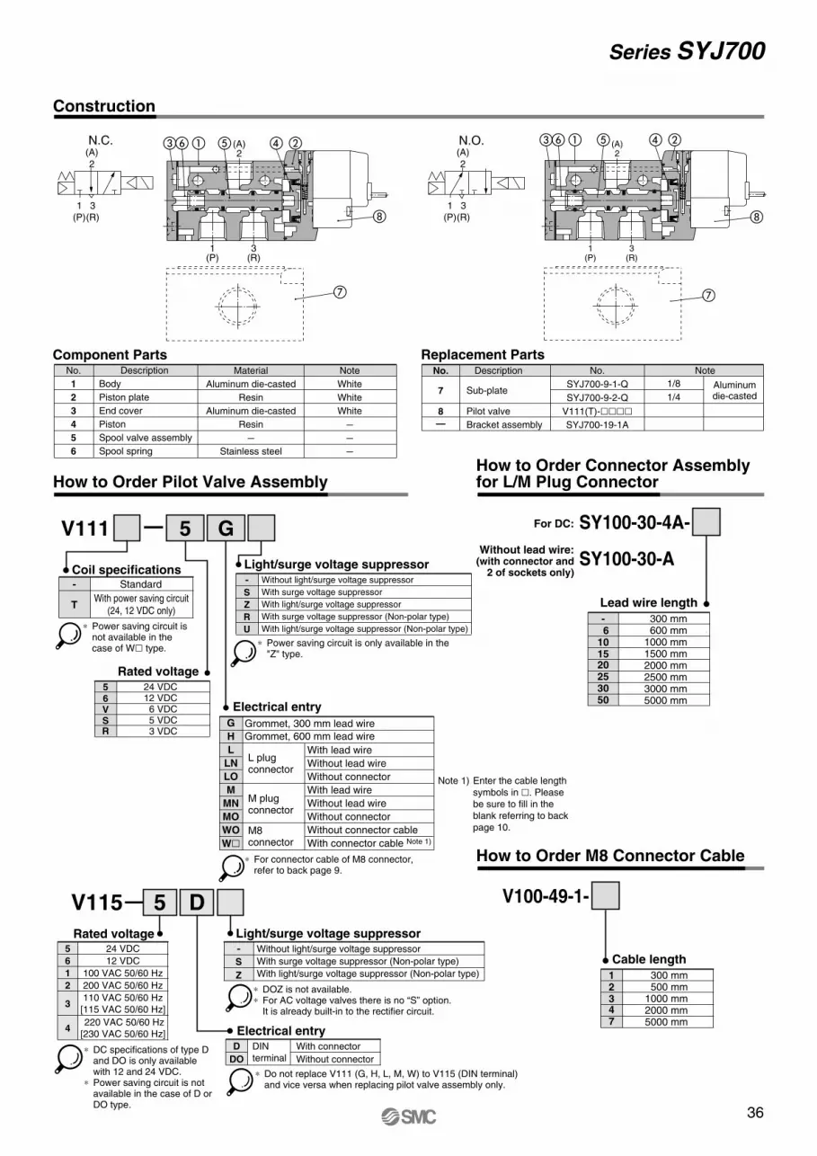
36
Series SYJ700
V111
5
6VSR
Construction
How to Order Pilot Valve AssemblyHow to Order Connector Assembly for L/M Plug Connector
5 G
24 VDC12 VDC6 VDC5 VDC3 VDC
Rated voltage
Electrical entry
(A)
2
N.C.
1
(P)
3
(R)
(A)
2
1
(P)
3
(R)
N.O.
� �
Component Parts Replacement PartsNo.
1
2
3
4
5
6
Description
Body
Piston plate
End cover
Piston
Spool valve assembly
Spool spring
Material
Aluminum die-casted
Resin
Aluminum die-casted
Resin
–
Stainless steel
Note
White
White
White
–
–
–
No.
8
—
Description
Pilot valve
Bracket assembly
NoteNo.
SYJ700-9-1-Q
SYJ700-9-2-Q
V111(T)-����SYJ700-19-1A
7 Sub-plate1/8
1/4
Aluminumdie-casted
How to Order M8 Connector Cable
V100-49-1-
12347
300 mm 500 mm1000 mm2000 mm5000 mm
Cable length
�� � � ��
�� � � ��
5 DV115
DIN
terminal
D With connector
DO Without connector
- Without light/surge voltage suppressor
With surge voltage suppressor (Non-polar type)
With light/surge voltage suppressor (Non-polar type)
S
Z
∗ DOZ is not available.∗ For AC voltage valves there is no “S” option.
It is already built-in to the rectifier circuit.
∗ Do not replace V111 (G, H, L, M, W) to V115 (DIN terminal) and vice versa when replacing pilot valve assembly only.
Rated voltage
Electrical entry
Light/surge voltage suppressor
(A)2
3(R)
1(P)
(A)2
3(R)
1(P)
∗ Power saving circuit is not available in the case of W� type.
-
T
Standard
With power saving circuit
(24, 12 VDC only)
Coil specifications
5 24 VDC
6 12 VDC
1 100 VAC 50/60 Hz
2 200 VAC 50/60 Hz
3
4 220 VAC 50/60 Hz
[230 VAC 50/60 Hz]
110 VAC 50/60 Hz
[115 VAC 50/60 Hz]
∗ DC specifications of type D and DO is only available with 12 and 24 VDC.
∗ Power saving circuit is not available in the case of D or DO type.
For DC:
Without lead wire:(with connector and
2 of sockets only)
SY100-30-4A-
SY100-30-A
- 6101520253050
300 mm 600 mm1000 mm1500 mm2000 mm2500 mm3000 mm5000 mm
Lead wire length
-
S
Z
R
U
Light/surge voltage suppressorWithout light/surge voltage suppressor
With surge voltage suppressor
With light/surge voltage suppressor
With surge voltage suppressor (Non-polar type)
With light/surge voltage suppressor (Non-polar type)
∗ Power saving circuit is only available in the "Z" type.
G
H
L
LN
LO
M
MN
MO
WO
W�
Grommet, 300 mm lead wire
Grommet, 600 mm lead wire
With lead wire
Without lead wire
Without connector
With lead wire
Without lead wire
Without connector
Without connector cable
With connector cable Note 1)
L plug connector
M plug connector
M8 connector
∗ For connector cable of M8 connector, refer to back page 9.
Note 1) Enter the cable length
symbols in �. Please
be sure to fill in the
blank referring to back
page 10.
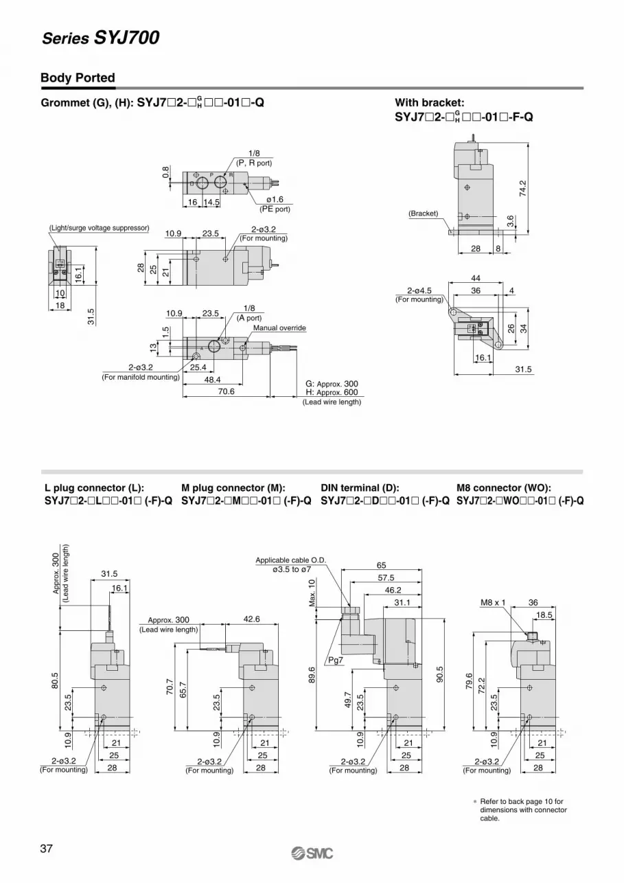
37
Series SYJ700
Body Ported
Grommet (G), (H): SYJ7�2-�GH ��-01�-Q With bracket:
SYJ7�2-�GH ��-01�-F-Q
L plug connector (L):
SYJ7�2-�L��-01� (-F)-QM plug connector (M):
SYJ7�2-�M��-01� (-F)-QDIN terminal (D):
SYJ7�2-�D��-01� (-F)-QM8 connector (WO):
SYJ7�2-�WO��-01� (-F)-Q
31.5
0.8
1.5
70.6
14.516
23.510.9
48.4
25.4
13
23.510.9
16.1
18
10
28
25
21
ø1.6(PE port)
2-ø3.2(For mounting)
G: Approx. 300H: Approx. 600
(Lead wire length)
1/8(A port)
(Light/surge voltage suppressor)
1/8(P, R port)
Manual override
2-ø3.2(For manifold mounting)
- +
RP
A
74.2
28
26
31.5
16.1
8
3.6
(Bracket)
2-ø4.5(For mounting)
4
34
44
36
+-
Approx. 300(Lead wire length)
42.6
79.6
72.2
18.5
23.5
10.9
31.1
23.5
10.9
Applicable cable O.D.
ø3.5 to ø7
Pg7
2-ø3.2(For mounting)
2-ø3.2(For mounting)
∗ Refer to back page 10 for dimensions with connector cable.
M8 x 1 36
65
46.2
57.5
Max. 10
89.6
90.5
49.7
28
25
21
28
25
21
23.5
10.9
31.5
16.1
23.5
10.9
Appro
x. 300
(Lead w
ire length
)
80.5
70.7
65.7
2-ø3.2(For mounting)
2-ø3.2(For mounting) 28
25
21
28
25
21
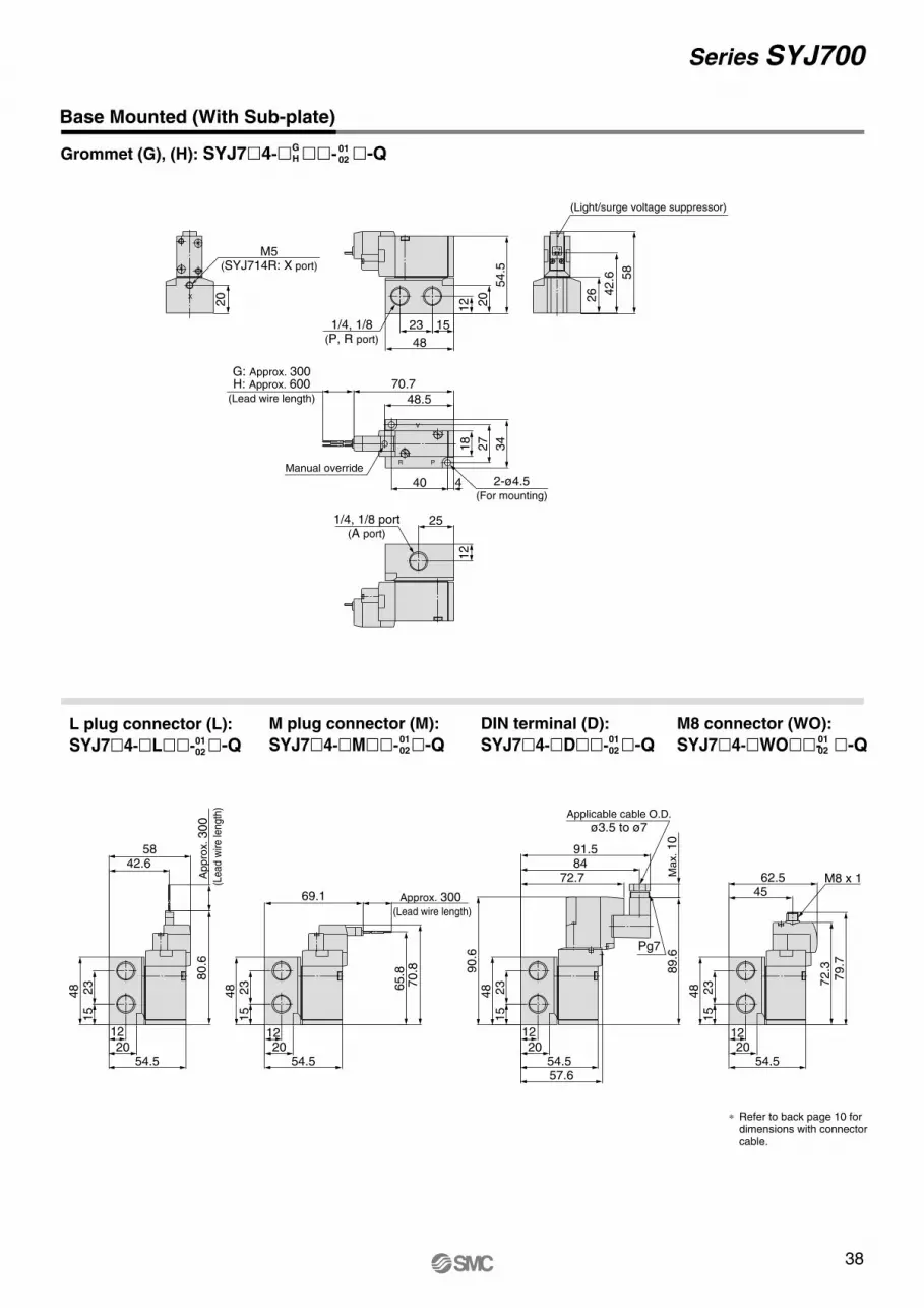
38
Series SYJ700
Grommet (G), (H): SYJ7�4-�GH ��- �-Q
Base Mounted (With Sub-plate)
L plug connector (L):
SYJ7�4-�L��- �-Q
M plug connector (M):
SYJ7�4-�M��- �-Q
0102
0102
0102
DIN terminal (D):
SYJ7�4-�D��- �-Q0102
M8 connector (WO):
SYJ7�4-�WO��- �-Q0102
70.7
20
G: Approx. 300H: Approx. 600
(Lead wire length) 48.5
40 4
Manual override
54.5
58
42.6
26
(Light/surge voltage suppressor)
1/4, 1/8 port(A port)
M5(SYJ714R: X port)
2-ø4.5(For mounting)
1/4, 1/8(P, R port)
X
A
R P18
20
25
12
12
48
23 15
34
27
+-
54.520
12
54.520
12
M8 x 1
∗ Refer to back page 10 for dimensions with connector cable.
Pg7
Applicable cable O.D.
ø3.5 to ø7
62.545
79.7
72.389.6
Max. 10
91.584
72.7
90.6
57.654.5
20
12
48 23
15
54.520
12
48 23
15
69.1
65.8
70.8
Approx. 300 (Lead wire length)
48 23
15
5842.6
Appro
x. 300
(Le
ad
wire
len
gth
)
80.6
48 23
15
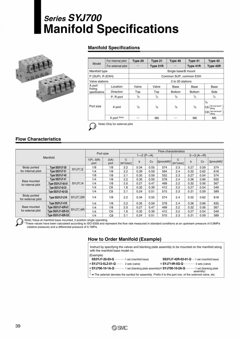
39
Manifold Specifications
Model
Manifold type
P (SUP), R (EXH)
Valve stations
A portPorting specifications
Port size
For internal pilot
For external pilot
Type 20 Type 21
Type 21R
Type 40
Location
Direction
P, R port
A port
X port Note)
Valve
Top
M5
Single base/B mount
Common SUP, common EXH
2 to 20 stations
Base
Bottom
1/8
Note) Only for external pilot
Type 41
Type 41R
Type 42
Type 42R
Base
Bottom
Base
Side
1/4
M5
1/4
M5
1/41/8
Valve
Top
1/8 1/8
1/8
C6
C8
1/81/8ø6 one-touch
fitting
ø8 one-touch
fitting
Manifold SpecificationsSeries SYJ700
Flow Characteristics
Note) Value at manifold base mounted, 2 position single operating.
*These values have been calculated according to ISO 6358 and represent the flow rate measured in standard conditions at an upstream pressure of 0.6MPa
(relative pressure) and a differential pressure of 0.1MPa.
Type SS3YJ7-20
Type SS3YJ7-21
Type SS3YJ7-40
Type SS3YJ7-41
Type SS3YJ7-42-01
Type SS3YJ7-42-C6
Type SS3YJ7-42-C8
Type SS3YJ7-21R
Type SS3YJ7-41R
Type SS3YJ7-42R-01
Type SS3YJ7-42R-C6
Type SS3YJ7-42R-C8
C
[dm3/(s•bar)]
1(P), 3(R)
port
2(A)
portb Cv
C
[dm3/(s•bar)]b Cv
1�2 (P�A) 2�3 (A�R)Manifold
Flow characteristicsPort size
1/8 2.2
2.2
2.1
2.2
2.0
1.6
2.1
2.2
2.2
2.0
1.6
2.1
0.34
0.39
0.35
0.35
0.27
0.32
0.24
0.34
0.35
0.27
0.32
0.24
0.55
0.59
0.59
0.59
0.47
0.39
0.51
0.55
0.59
0.47
0.39
0.51
2.3
2.4
2.3
2.4
2.2
2.2
2.3
2.4
2.4
2.2
2.2
2.3
0.27
0.32
0.27
0.36
0.32
0.27
0.31
0.32
0.36
0.32
0.27
0.31
0.59
0.62
0.54
0.66
0.56
0.54
0.59
0.62
0.66
0.56
0.54
0.59
1/8
1/8
1/8
1/8
C6
C8
1/8
1/8
1/8
C6
1/8
1/4
1/8
1/4
1/4
1/4
1/4
1/4
1/4
1/4
1/4
C81/4
SYJ7�2
SYJ7�4
SYJ7�2R
SYJ7�4R
Body ported
for internal pilot
Base mounted
for internal pilot
Body ported
for external pilot
Base mounted
for external pilot
How to Order Manifold (Example)
Instruct by specifying the valves and blanking plate assembly to be mounted on the manifold along
with the manifold base model no.
(Example)
SS3YJ7-20-03-Q .............1 set (manifold base)
SYJ712-5LZ-01-Q......... 2 sets (valve)
SYJ700-10-1A-Q............. 1 set (blanking plate assembly)
SS3YJ7-42R-03-01-Q ....1 set (manifold base)
SYJ714R-5G-Q............... 2 sets (valve)
SYJ700-10-2A-Q.............1 set (blanking plate assembly)
The asterisk denotes the symbol for assembly. Prefix it to the part nos. of the solenoid valve, etc.
∗∗
∗∗
Q[l/min(ANR)]*
574
594
552
578
499
412
515
574
578
499
412
515
Q[l/min(ANR)]*
574
618
574
635
567
549
589
618
635
567
549
589
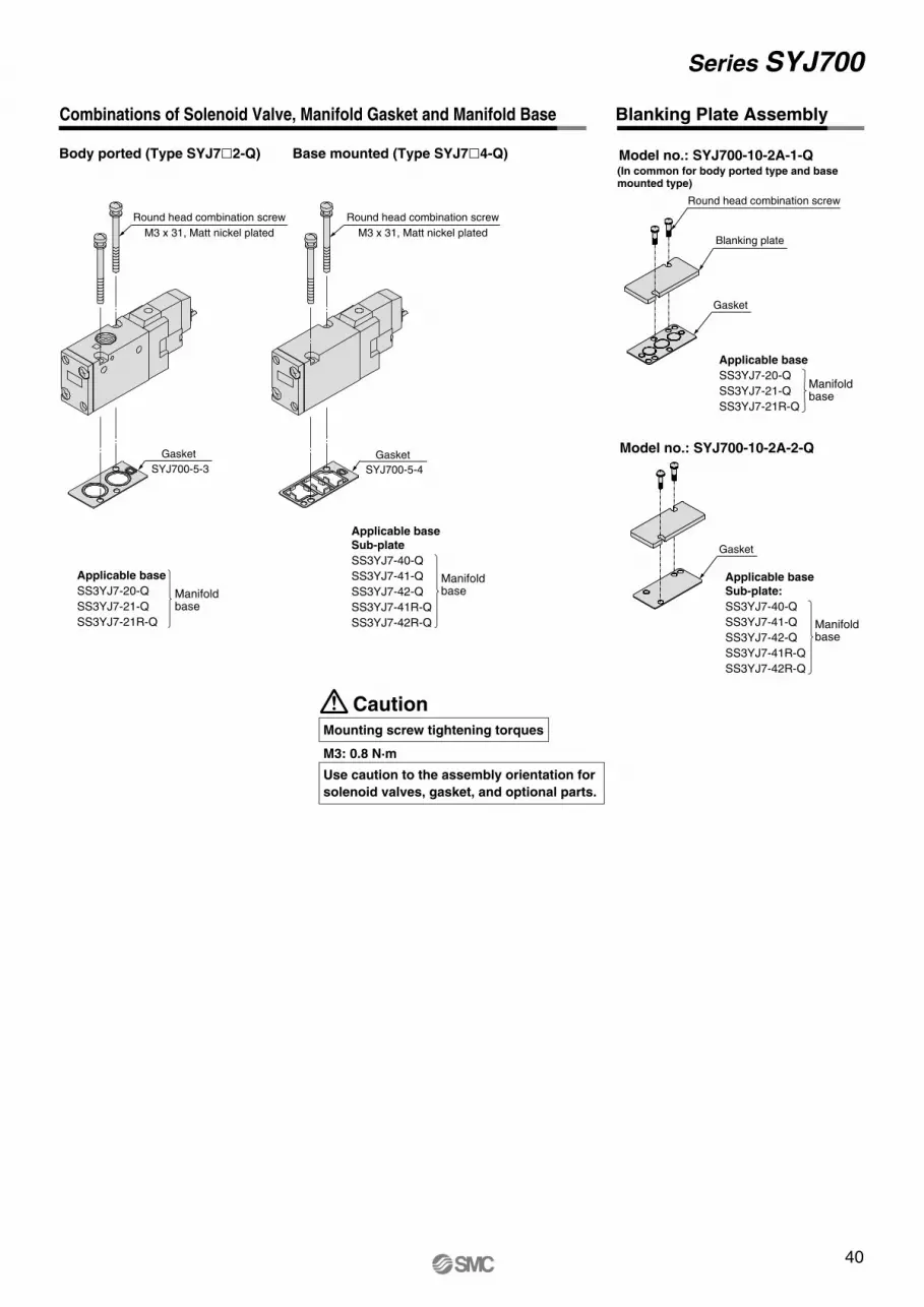
40
Combinations of Solenoid Valve, Manifold Gasket and Manifold Base Blanking Plate Assembly
Series SYJ700
Body ported (Type SYJ7�2-Q) Base mounted (Type SYJ7�4-Q)
Applicable base
SS3YJ7-20-Q
SS3YJ7-21-Q
SS3YJ7-21R-Q
Applicable base Sub-plate
SS3YJ7-40-Q
SS3YJ7-41-Q
SS3YJ7-42-Q
SS3YJ7-41R-Q
SS3YJ7-42R-Q
ManifoldbaseManifold
base
Gasket Gasket
SYJ700-5-3 SYJ700-5-4
(In common for body ported type and base mounted type)
Model no.: SYJ700-10-2A-1-Q
Gasket
Blanking plate
Round head combination screw
Round head combination screw
M3 x 31, Matt nickel plated
Round head combination screw
M3 x 31, Matt nickel plated
CautionMounting screw tightening torques
M3: 0.8 N·m
Use caution to the assembly orientation for
solenoid valves, gasket, and optional parts.
Model no.: SYJ700-10-2A-2-Q
Applicable base Sub-plate:
SS3YJ7-40-Q
SS3YJ7-41-Q
SS3YJ7-42-Q
SS3YJ7-41R-Q
SS3YJ7-42R-Q
Manifoldbase
Applicable base
SS3YJ7-20-Q
SS3YJ7-21-Q
SS3YJ7-21R-Q
Manifoldbase
Gasket
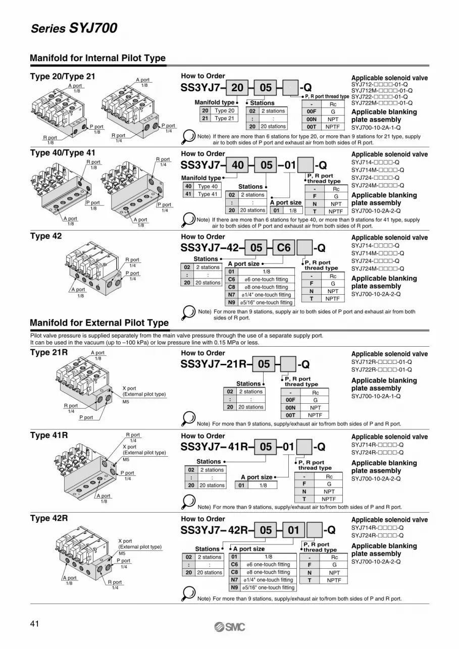
41
Series SYJ700
Type 20/Type 21
Type 40/Type 41
Type 42
Type 21R
Type 41R
How to Order Applicable solenoid valveSYJ712-����-01-QSYJ712M-����-01-QSYJ722-����-01-QSYJ722M-����-01-Q
Applicable blankingplate assemblySYJ700-10-2A-1-Q
Applicable solenoid valveSYJ714-����-Q
SYJ714M-����-Q
SYJ724-����-Q
SYJ724M-����-Q
Applicable blankingplate assemblySYJ700-10-2A-2-Q
Applicable solenoid valveSYJ714-����-Q
SYJ714M-����-Q
SYJ724-����-Q
SYJ724M-����-Q
Applicable blankingplate assemblySYJ700-10-2A-2-Q
Applicable solenoid valveSYJ712R-����-01-Q
SYJ722R-����-01-Q
Applicable blankingplate assemblySYJ700-10-2A-1-Q
Applicable solenoid valveSYJ714R-����-Q
SYJ724R-����-Q
Applicable blankingplate assemblySYJ700-10-2A-2-Q
Note) If there are more than 6 stations for type 20, or more than 9 stations for 21 type, supply air to both sides of P port and exhaust air from both sides of R port.
SS3YJ7-- 20 -- 05 --
How to Order
SS3YJ7-- 40 -- 05 --01
How to Order
SS3YJ7-- 41R-- 05 --01
01 1/8
A port size
How to Order
SS3YJ7--21R-- 05 --
How to Order
SS3YJ7--42-- 05 -- C6
01
C6
C8
N7
N9
1/8
ø6 one-touch fitting
ø8 one-touch fitting
ø1/4" one-touch fitting
ø5/16" one-touch fitting
A port size
Pilot valve pressure is supplied separately from the main valve pressure through the use of a separate supply port.
It can be used in the vacuum (up to –100 kPa) or low pressure line with 0.15 MPa or less.
Manifold for Internal Pilot Type
Manifold for External Pilot Type
Type 42R Applicable solenoid valveSYJ714R-����-Q
SYJ724R-����-Q
Applicable blankingplate assemblySYJ700-10-2A-2-Q
How to Order
SS3YJ7-- 42R-- 05 -- 01
01
C6
C8
N7
N9
1/8
ø6 one-touch fitting
ø8 one-touch fitting
ø1/4" one-touch fitting
ø5/16" one-touch fitting
A port size
01 1/8
A port size
40
41
Type 40
Type 41
P port 1/8
R port 1/8
A port1/8
P port 1/4
R port 1/4
A port 1/8
P port 1/4
R port 1/4
A port 1/8
P port 1/8
R port 1/8
A port
1/8
P port 1/4
R port 1/4
A port 1/8
P port 1/4
X port(External pilot type)
M5
R port 1/4
P port
1/4
X port(External pilot type)
M5
R port 1/4
A port1/8
A port 1/8
R port 1/4
X port(External pilot type)
M5
P port
A port1/8
Manifold type
02
:
20
2 stations
:
20 stations
Stations
02
:
20
2 stations
:
20 stations
Stations
02
:
20
2 stations
:
20 stations
Stations
02
:
20
2 stations
:
20 stations
Stations
02
:
20
2 stations
:
20 stations
Stations
02
:
20
2 stations
:
20 stations
Stations
20
21
Type 20
Type 21
Manifold type
Note) If there are more than 6 stations for type 40, or more than 9 stations for 41 type, supply air to both sides of P port and exhaust air from both sides of R port.
Note) For more than 9 stations, supply air to both sides of P port and exhaust air from both sides of R port.
Note) For more than 9 stations, supply/exhaust air to/from both sides of P and R port.
Note) For more than 9 stations, supply/exhaust air to/from both sides of P and R port.
Note) For more than 9 stations, supply/exhaust air to/from both sides of P and R port.
Rc
G
NPT
NPTF
P, R port thread type
00F
00N
00T
-
Rc
G
NPT
NPTF
P, R portthread type
F
N
T
-
Rc
G
NPT
NPTF
P, R portthread type
F
N
T
-
Rc
G
NPT
NPTF
P, R portthread type
00F
00N
00T
-
Rc
G
NPT
NPTF
P, R portthread type
F
N
T
-
Rc
G
NPT
NPTF
P, R portthread type
F
N
T
-
-+
-+
-+
-+
R
P-+
-+
-+
-+
R
P
A
A
A
A
-+
-+
-+
-+A
A
PR
X
-+
-+
-+
-+
PR
X
A
A
R
P
X
-+
-+
-+
-+
PR
X
-Q
-Q
-Q
-Q
-Q
-Q
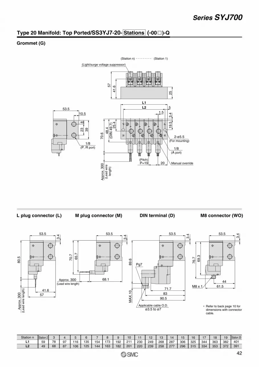
42
Series SYJ700
Station n
L1
L2
Station 2
59
49
3
78
68
4
97
87
5
116
106
6
135
125
7
154
144
8
173
163
9
192
182
10
211
201
11
230
220
12
249
239
13
268
258
14
287
277
15
306
296
16
325
315
17
344
334
18
363
353
19
382
372
Station 20
401
391
Grommet (G)
L plug connector (L) M plug connector (M)
Type 20 Manifold: Top Ported/SS3YJ7-20- Stations (-00�)-Q
DIN terminal (D) M8 connector (WO)
∗ Refer to back page 10 for dimensions with connector cable.
RP
RP
70.6
25
5
10.5
39
23
8
L2
L1
19.5
48.4
(DIN
49.7
)
3.4
25.4
Appro
x. 300
(Lead w
ire
length
)53.5
57
41.6
(Pitch)P=19 20
1.5
(Light/surge voltage suppressor)
1/8(P, R port)
Manual override
1/8(A port)
2-ø5.5(For mounting)
AAAA
+-+-+-+-
(Station n) (Station 1)
68.1
M8 x 1
Pg7
76.7
69.3
61.5
44
89.6
71.7
90.5
83
3.4
Applicable cable O.D.
ø3.5 to ø7
53.5 53.5
3.43.4
Approx. 300 (Lead wire length)
57
Appro
x. 300
(Lead w
ire length
)
41.6
80.5
53.5
70.7
65.7
53.5
3.4
MA
X.1
0
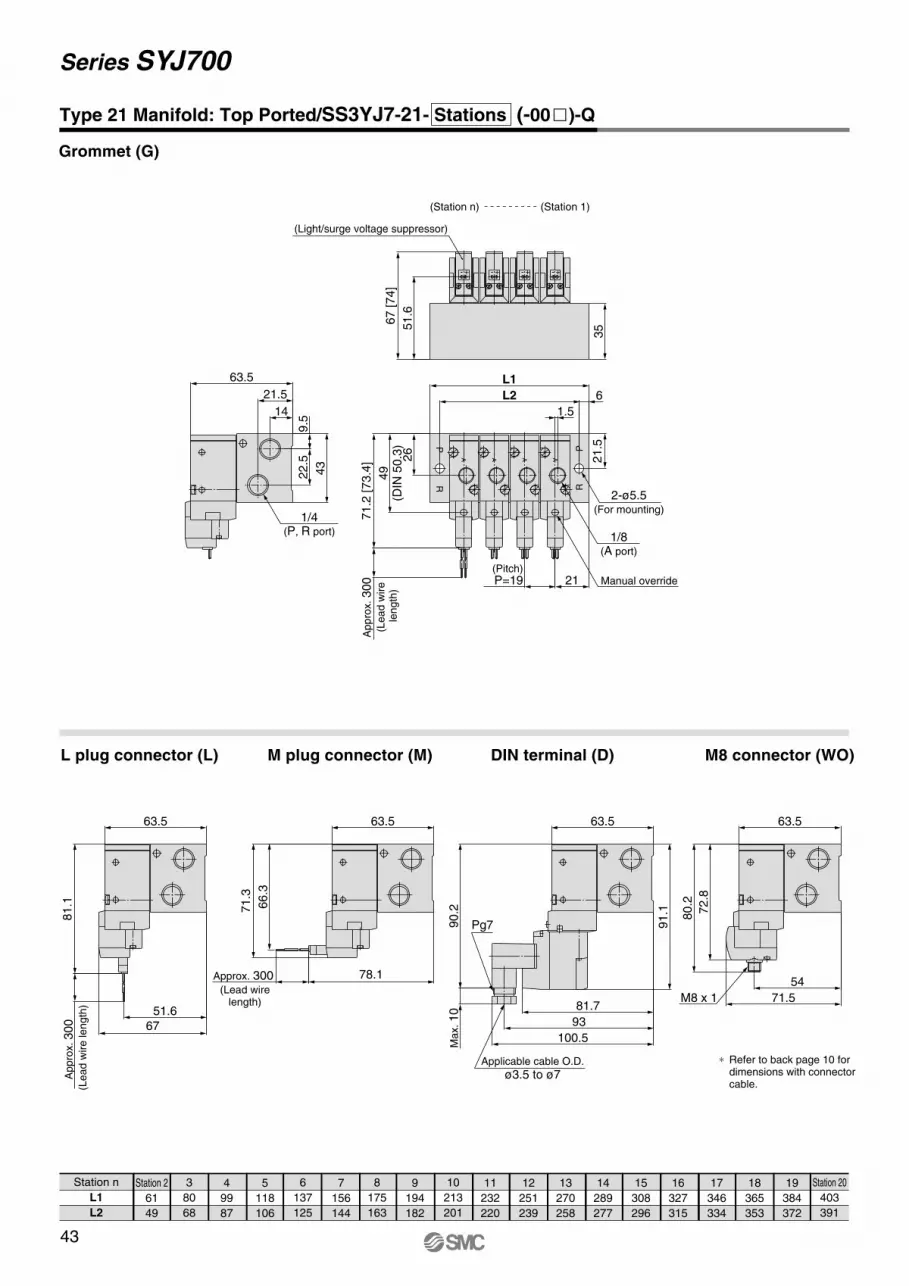
43
Series SYJ700
Station n
L1
L2
Station 2
61
49
3
80
68
4
99
87
5
118
106
6
137
125
7
156
144
8
175
163
9
194
182
10
213
201
11
232
220
12
251
239
13
270
258
14
289
277
15
308
296
16
327
315
17
346
334
18
365
353
19
384
372
Station 20
403
391
Grommet (G)
L plug connector (L) M plug connector (M) DIN terminal (D) M8 connector (WO)
Type 21 Manifold: Top Ported/SS3YJ7-21- Stations (-00�)-Q
71.2
[73.4
]
21.5
14
43
22.5
9.5
6L2
L1
21.5
35
Appro
x. 300
(Lead w
ire
length
)49
(DIN
50.3
)
63.567 [74]
51.6
Manual override
1/8(A port)
1.5
2-ø5.5(For mounting)
(Pitch)P=19 21
26
(Station 1)(Station n)
(Light/surge voltage suppressor)
1/4(P, R port)
RP
RP
AAAA
+-+-+-+-
78.1
∗ Refer to back page 10 for dimensions with connector cable.
M8 x 1
Applicable cable O.D.
ø3.5 to ø7
Pg7
71.5
54
80.2
72.8
90.2
Max. 10 81.7
100.5
93
63.5 63.5
91.1
Approx. 300 (Lead wire
length)
67
51.6
Appro
x. 300
(Lead w
ire length
)
81.1
63.563.5
71.3
66.3
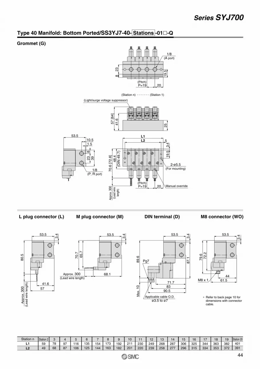
44
Series SYJ700
Station n
L1
L2
Station 2
59
49
3
78
68
4
97
87
5
116
106
6
135
125
7
154
144
8
173
163
9
192
182
10
211
201
11
230
220
12
249
239
13
268
258
14
287
277
15
306
296
16
325
315
17
344
334
18
363
353
19
382
372
Station 20
401
391
Grommet (G)
L plug connector (L) M plug connector (M)
Type 40 Manifold: Bottom Ported/SS3YJ7-40- Stations -01�-Q
DIN terminal (D) M8 connector (WO)
70.6
[72.8
]
1.55L2
L1
39
23
820
19.52
38
25
48.4
(DIN
49.7
)
19.5
3.4
10.553.5
App
rox.
300
(L
ead
wire
le
ngth
)
1/8(A port)
57 [64]
41.6
(Pitch)P=19 20
(Pitch)P=19
Manual override
2-ø5.5(For mounting)
(Light/surge voltage suppressor)
(Station n) (Station 1)
1/8(P, R port)
+-+-+-+-
68.1
∗ Refer to back page 10 for dimensions with connector cable.
M8 x 1
Applicable cable O.D.
ø3.5 to ø7
Pg7
61.544
79
.672.2
89.6
Max. 10
90.58371.7
3.4
87.1
3.453.5 53.5
3.4
3.4
Approx. 300 (Lead wire length)
Appro
x. 300
(Lead w
ire length
)
41.6
80.5
70.7
65.7
53.5
57
53.5
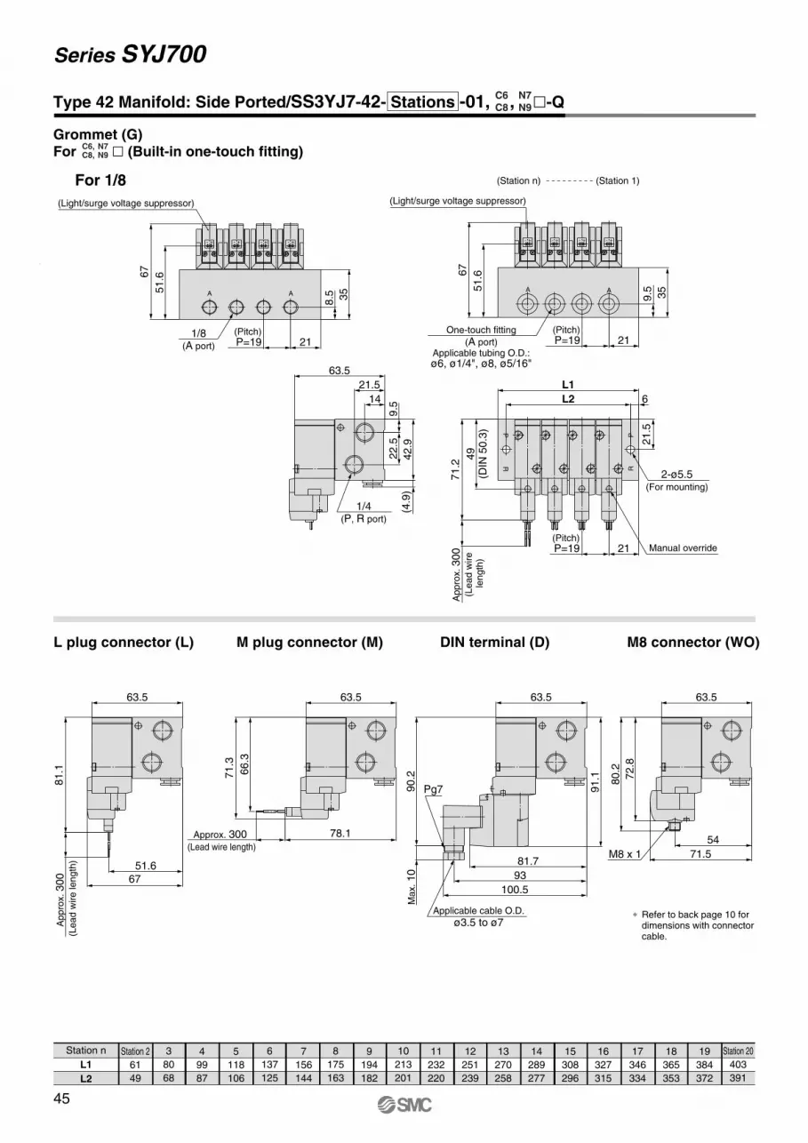
45
Series SYJ700
Station n
L1
L2
Station 2
61
49
3
80
68
4
99
87
5
118
106
6
137
125
7
156
144
8
175
163
9
194
182
10
213
201
11
232
220
12
251
239
13
270
258
14
289
277
15
308
296
16
327
315
17
346
334
18
365
353
19
384
372
Station 20
403
391
L plug connector (L) M plug connector (M)
For 1/8
Type 42 Manifold: Side Ported/SS3YJ7-42- Stations -01, , �-Q
DIN terminal (D) M8 connector (WO)
35
71.2
35
42.9
22
.59.5
21.5
14 6L2
L1
21.5
Appro
x. 300
(Lead w
ire
length
)49
(DIN
50.3
)
8.5
(Pitch)P=19 21
1/8(A port)
67
51.6
(Light/surge voltage suppressor)
AA
(Pitch)P=19 21
67
51.6
9.5
(4.9
)
63.5
(Pitch)P=19 21 Manual override
(Station 1)
2-ø5.5(For mounting)
(Station n)
(Light/surge voltage suppressor)
One-touch fitting
(A port)Applicable tubing O.D.:ø6, ø1/4", ø8, ø5/16"
1/4(P, R port)
AA
R
R
P
P
+-+-+-+-+-+-+-+-
78.1
∗ Refer to back page 10 for dimensions with connector cable.
M8 x 1
Applicable cable O.D.
ø3.5 to ø7
Pg7
54
71.5
80.2
72.8
90.2
Max. 10
100.5
93
81.7
63.5 63.5
91.1
Approx. 300 (Lead wire length)
67
51.6
Appro
x. 300
(Lead w
ire length
)
81.1
63.563.5
71.3
66.3
N7N9
C6C8
Grommet (G)For � (Built-in one-touch fitting)
N7N9
C6,C8,
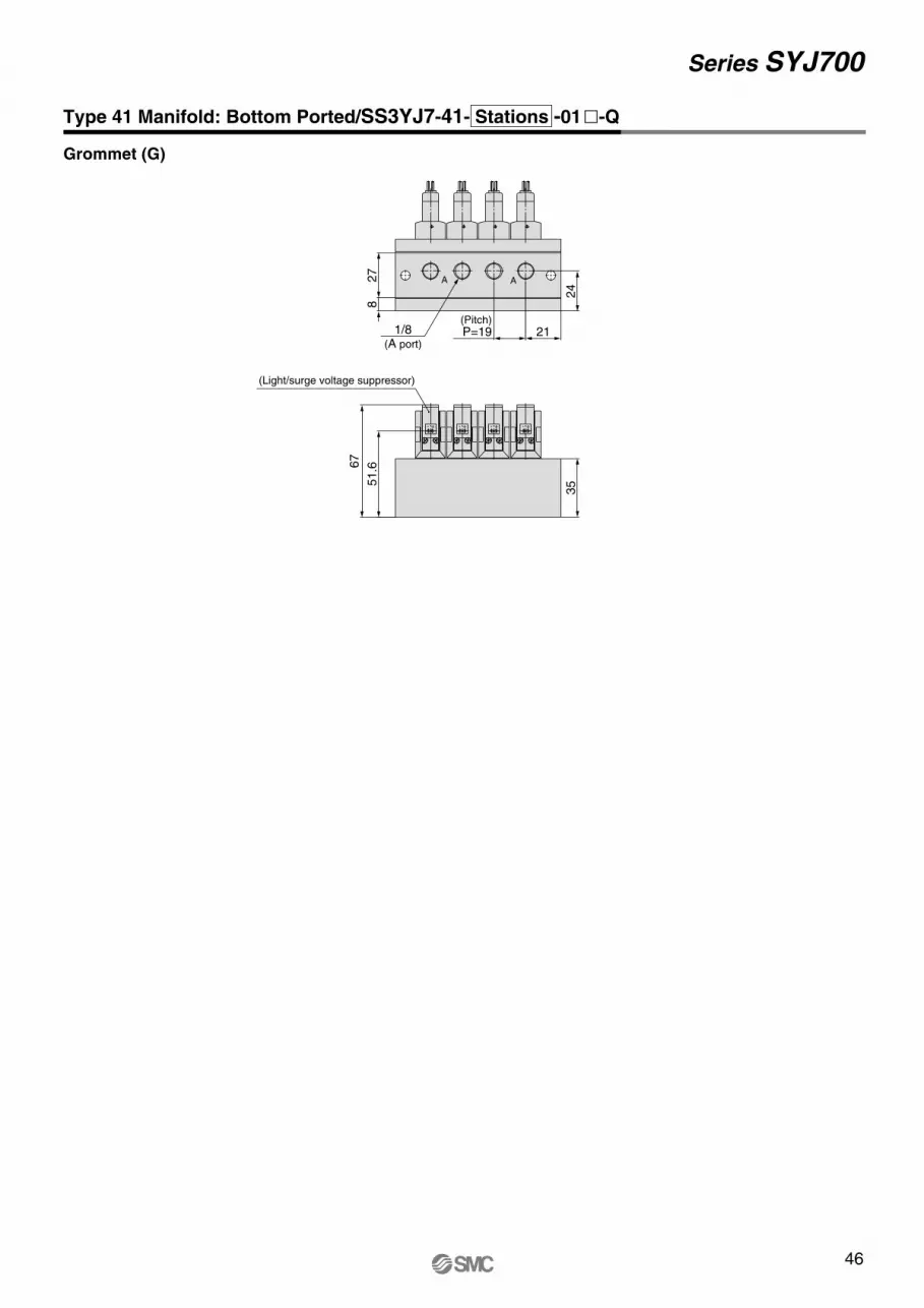
46
Series SYJ700
Type 41 Manifold: Bottom Ported/SS3YJ7-41- Stations -01�-Q
Grommet (G)
(Pitch)P=191/8
(A port)21
24
27
8
35
AA
(Light/surge voltage suppressor)
67
51.6
+-+-+-+-
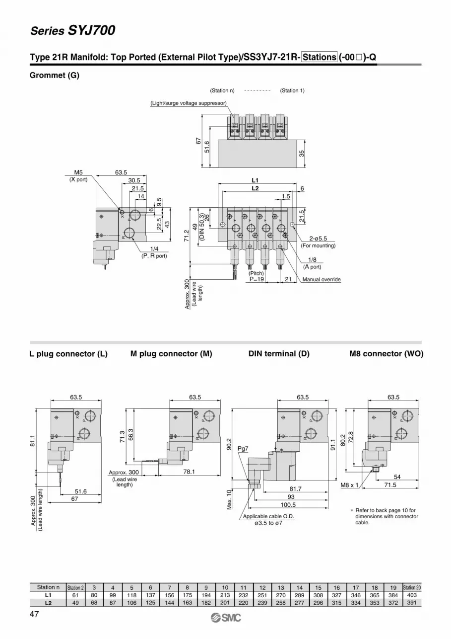
47
Series SYJ700
Station n
L1
L2
Station 2
61
49
3
80
68
4
99
87
5
118
106
6
137
125
7
156
144
8
175
163
9
194
182
10
213
201
11
232
220
12
251
239
13
270
258
14
289
277
15
308
296
16
327
315
17
346
334
18
365
353
19
384
372
Station 20
403
391
L plug connector (L) M plug connector (M) DIN terminal (D) M8 connector (WO)
Grommet (G)
Type 21R Manifold: Top Ported (External Pilot Type)/SS3YJ7-21R- Stations (-00�)-Q
71.2
35
6
21.5
L2
L130.5
21.5
14
43
22.5
9.5
6
63.5
49
(DIN
50.3
)
Appro
x. 300
(Lead w
ire
length
)
1/8(A port)
26
(Pitch)P=19 21
1.567
51.6
M5(X port)
1/4(P, R port)
X
P
R
Manual override
(Station 1)
2-ø5.5(For mounting)
(Station n)
(Light/surge voltage suppressor)
AAA
+-+-+-+-
A
78.1
∗ Refer to back page 10 for dimensions with connector cable.
M8 x 1
Applicable cable O.D.
ø3.5 to ø7
Pg7
X
P
R
X
P
R
80.2
72.8
71.5
54
100.5
93
81.7
90.2
Max. 10
91.1
63.5 63.5
67
51.6
Appro
x. 300
(Lead w
ire length
)
63.5
Approx. 300 (Lead wire
length)
71.3
66.3
81.1
63.5
X
P
R
X
P
R
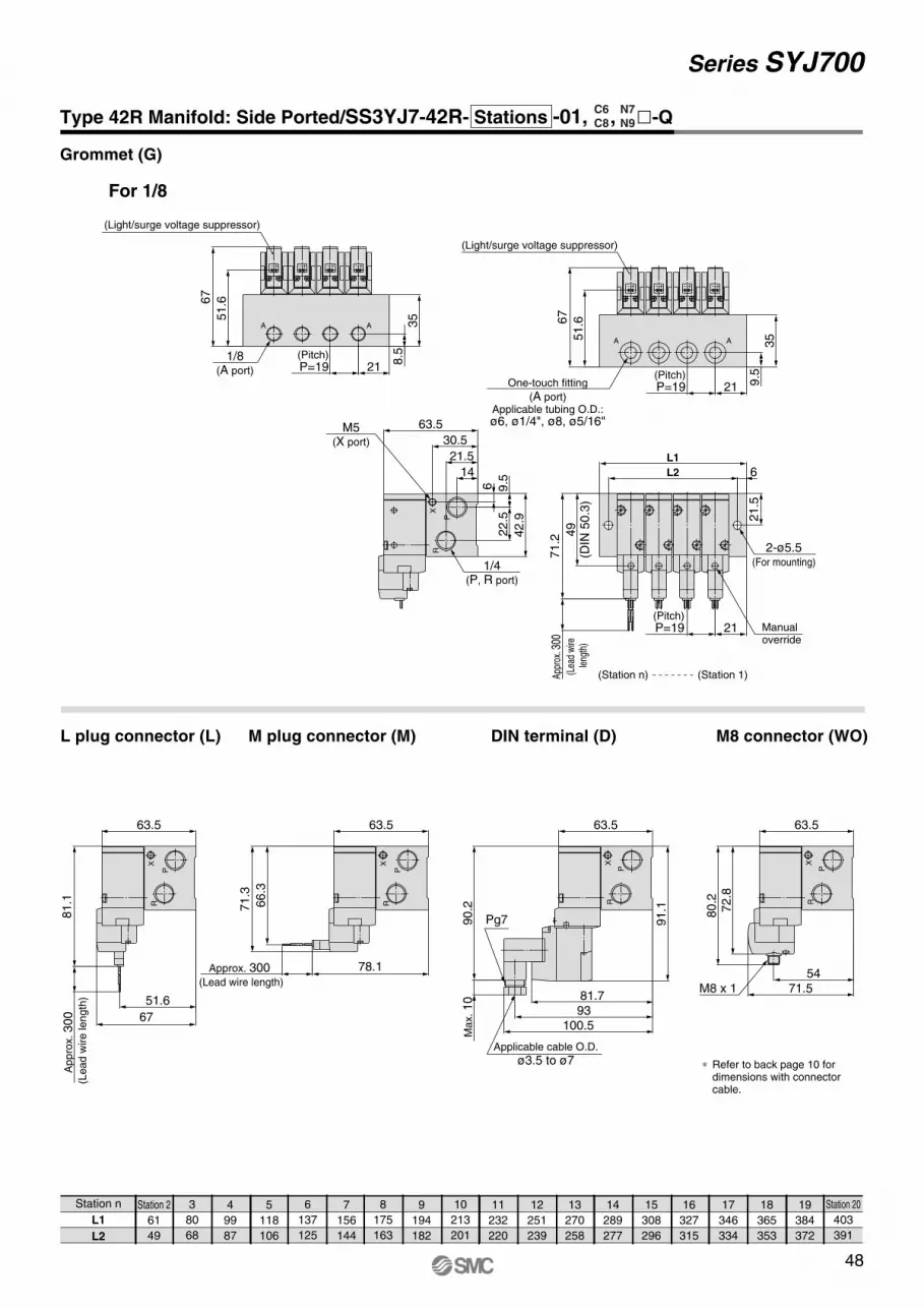
48
Series SYJ700
Station n
L1
L2
Station 2
61
49
3
80
68
4
99
87
5
118
106
6
137
125
7
156
144
8
175
163
9
194
182
10
213
201
11
232
220
12
251
239
13
270
258
14
289
277
15
308
296
16
327
315
17
346
334
18
365
353
19
384
372
Station 20
403
391
Grommet (G)
L plug connector (L) M plug connector (M) M8 connector (WO)DIN terminal (D)
Type 42R Manifold: Side Ported/SS3YJ7-42R- Stations -01, , �-Q
For 1/8
35
71.2
6
6L2
L1
21.5
30.5
21.5
14
42.9
22.5
9.5
(Pitch)P=19 21
App
rox.
300
(L
ead
wire
le
ngth
)49
(DIN
50.3
)
63.5
AA
M5(X port)
9.5(Pitch)
P=19 21
67
51.6
One-touch fitting
(A port)Applicable tubing O.D.:ø6, ø1/4", ø8, ø5/16"
R
P
X
Manualoverride
2-ø5.5(For mounting)
(Light/surge voltage suppressor)
(Station n) (Station 1)
1/4(P, R port)
+- +- +- +-
(Pitch)P=19 21
35
8.5
AA
67
51.6
1/8(A port)
(Light/surge voltage suppressor)
+-+-+-+-
M8 x 1
78.1
∗ Refer to back page 10 for dimensions with connector cable.
Applicable cable O.D.
ø3.5 to ø7
Pg7
X
P
R
X
P
R
80.2
72.8
71.554
100.59381.7
90.2
Ma
x. 10
91.1
63.5 63.5
Approx. 300 (Lead wire length)
67
Ap
pro
x. 300
(Le
ad
wire
le
ng
th) 51.6
81.1
71.3
66.3
63.563.5
R
P
X
R
P
X
N7N9
C6C8
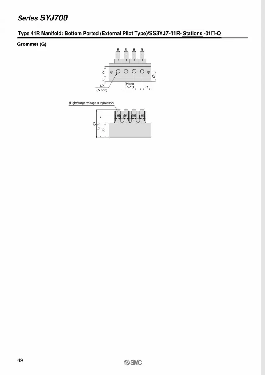
49
Series SYJ700
Type 41R Manifold: Bottom Ported (External Pilot Type)/SS3YJ7-41R- Stations -01�-Q
35
(Pitch)P=19 21
24
27
8
67
51.6
1/8(A port)
(Light/surge voltage suppressor)
+-+-+-+-
Grommet (G)

50
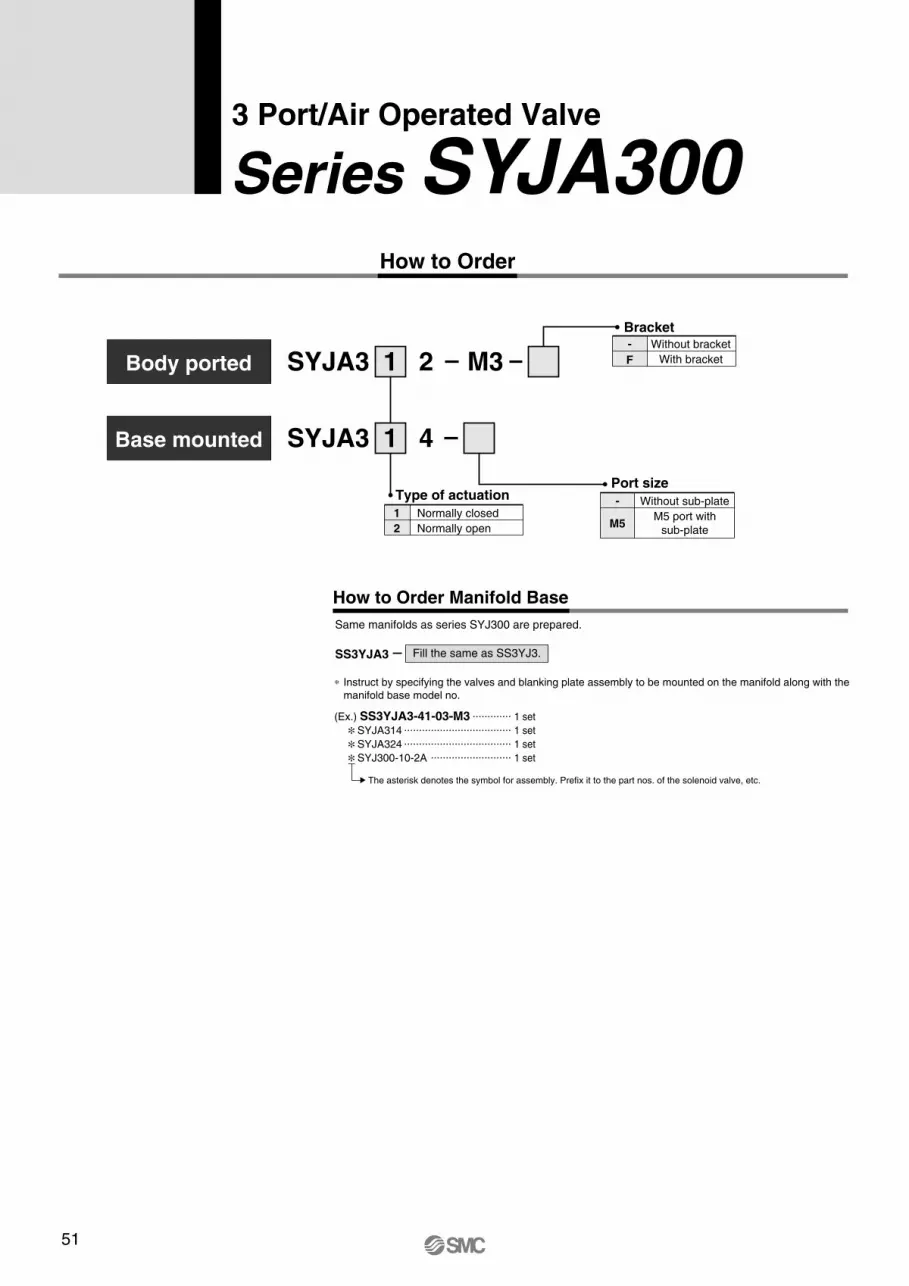
How to Order Manifold Base
Same manifolds as series SYJ300 are prepared.
∗ Instruct by specifying the valves and blanking plate assembly to be mounted on the manifold along with the
manifold base model no.
(Ex.) SS3YJA3-41-03-M3 ............. 1 set
∗SYJA314 .................................... 1 set
∗SYJA324 .................................... 1 set
∗SYJ300-10-2A ........................... 1 set
SS3YJA3 Fill the same as SS3YJ3.
51
How to Order
Normally open
Normally closed
2
1
Type of actuation
SYJA3 21
SYJA3 41
Without sub-plate
Port size
M5 port with
sub-plateM5
-
Without bracket
With bracketF
-
M3
Bracket
The asterisk denotes the symbol for assembly. Prefix it to the part nos. of the solenoid valve, etc.
Series SYJA3003 Port/Air Operated Valve
Body ported
Base mounted
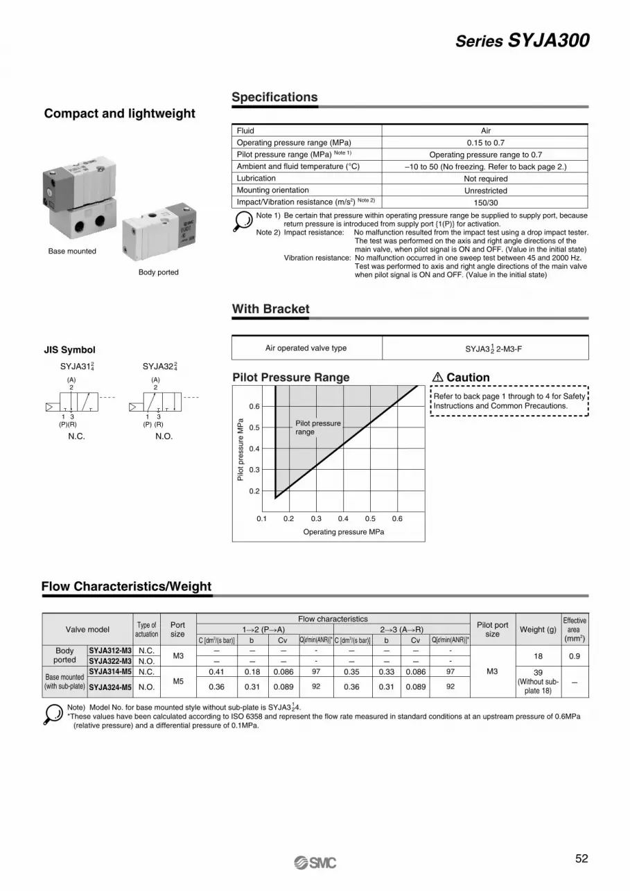
Flow Characteristics/Weight
Series SYJA300
Note) Model No. for base mounted style without sub-plate is SYJA3 4.
*These values have been calculated according to ISO 6358 and represent the flow rate measured in standard conditions at an upstream pressure of 0.6MPa
(relative pressure) and a differential pressure of 0.1MPa.
JIS Symbol
SYJA3124 SYJA322
4
Compact and lightweight
N.C. N.O.
(A)2
1(P)
3(R)
(A)2
1(P)
3(R)
Specifications
Fluid
Operating pressure range (MPa)
Pilot pressure range (MPa) Note 1)
Ambient and fluid temperature (°C)
Lubrication
Mounting orientation
Impact/Vibration resistance (m/s2) Note 2)
Air
0.15 to 0.7
Operating pressure range to 0.7
–10 to 50 (No freezing. Refer to back page 2.)
Not required
Unrestricted
150/30
Pilot Pressure Range
Refer to back page 1 through to 4 for Safety
Instructions and Common Precautions.
Caution
SYJA312-M3
SYJA322-M3
SYJA314-M5
SYJA324-M5
C [dm3/(s bar)] b Cv C [dm3/(s bar)] b Cv
1�2 (P�A) 2�3 (A�R)Valve model
Flow characteristics
Weight (g)Effective
area (mm2)
Pilot portsize
Type ofactuation
Portsize
M3
M3
18 0.9
–
39(Without sub-
plate 18)
–
–
0.41
0.36
–
–
0.18
0.31
–
–
0.086
0.089
–
–
0.35
0.36
–
–
0.33
0.31
–
–
0.086
0.089M5
N.C.
N.O.
N.C.
N.O.
Bodyported
Base mounted(with sub-plate)
12
52
Base mounted
Body ported
0.6
0.5
0.4
0.3
0.2
0.1 0.2 0.3 0.4 0.5 0.6
Operating pressure MPa
Pilo
t p
ressu
re M
Pa Pilot pressure
range
Note 1) Be certain that pressure within operating pressure range be supplied to supply port, because return pressure is introduced from supply port {1(P)} for activation.
Note 2) Impact resistance: No malfunction resulted from the impact test using a drop impact tester. The test was performed on the axis and right angle directions of the main valve, when pilot signal is ON and OFF. (Value in the initial state)
Vibration resistance: No malfunction occurred in one sweep test between 45 and 2000 Hz.Test was performed to axis and right angle directions of the main valve when pilot signal is ON and OFF. (Value in the initial state)
Q[l/min(ANR)]*
-
-
97
92
Q[l/min(ANR)]*
-
-
97
92
With Bracket
Air operated valve type SYJA3 2-M3-F12
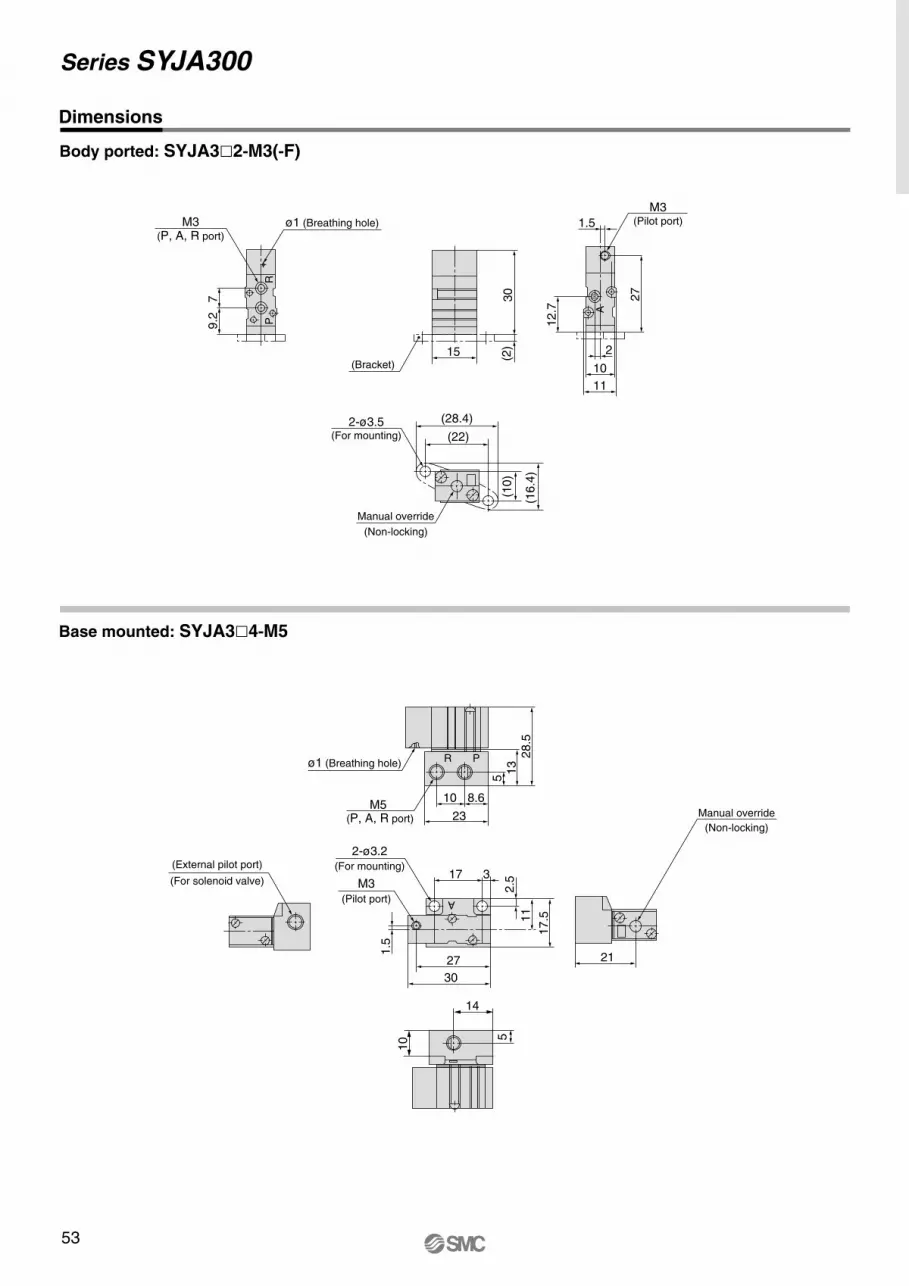
Series SYJA300
Dimensions
Body ported: SYJA3�2-M3(-F)
Base mounted: SYJA3�4-M5
Manual override
(Non-locking)
(For mounting)
(Bracket)
(Pilot port)
Manual override
(Non-locking)
(For mounting)
(Pilot port)
(For solenoid valve)
(28.4)
(22)
11
27
7M3
(P, A, R port)
9.2
RP
15
30
(2)
12.7
10
M3
1.5
2
(16.4
)
(10)
2-ø3.5
ø1 (Breathing hole)
14
17 3
1.5
2.5
27
23
8.610
17.5
28.5
13
5
11
30
21
10 5
2-ø3.2
ø1 (Breathing hole)
(P, A, R port)
M5
M3
A
(External pilot port)
PR
A
53
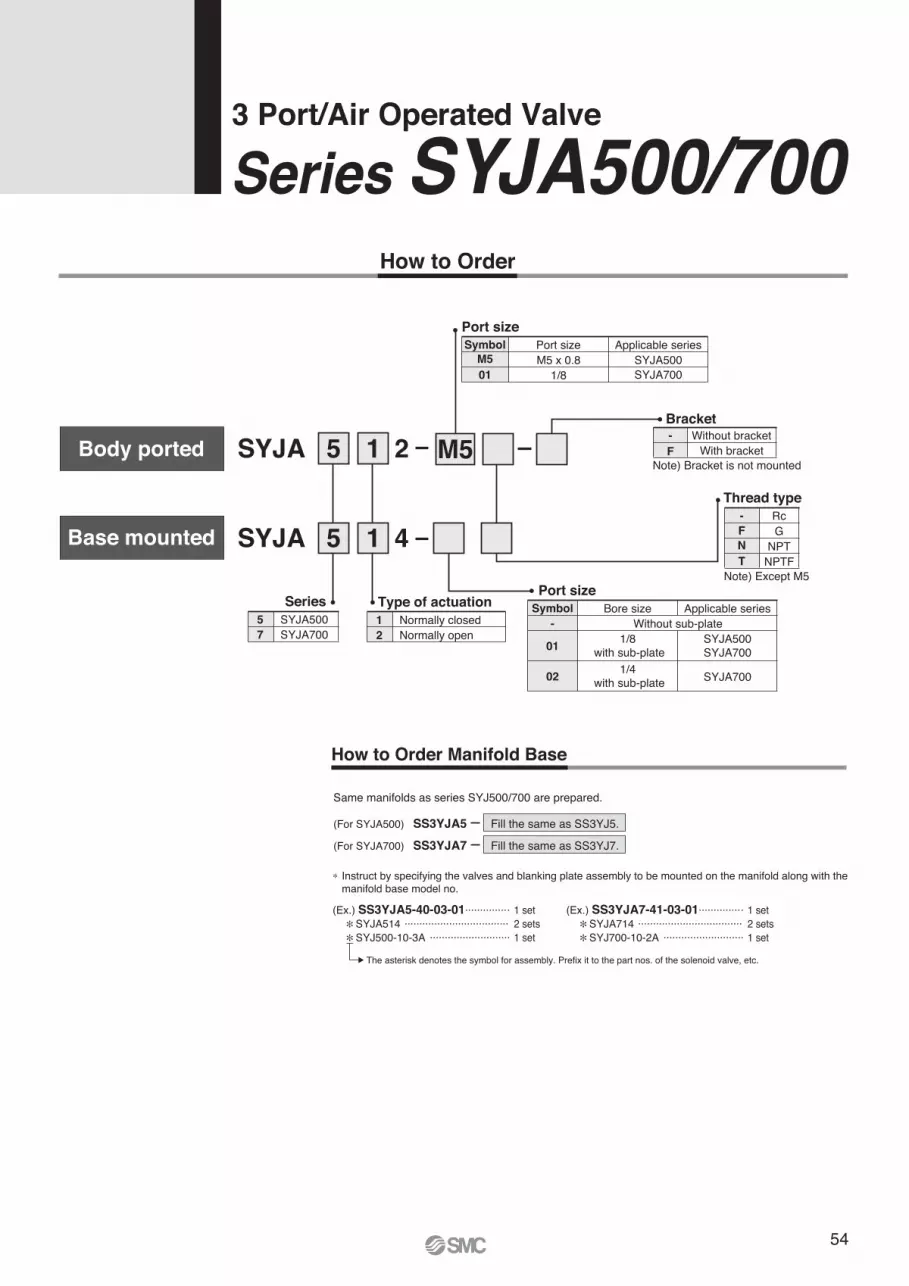
Normally openNormally closed
2
1
Type of actuation
How to Order Manifold Base
Same manifolds as series SYJ500/700 are prepared.
SS3YJA5 Fill the same as SS3YJ5.(For SYJA500)
SS3YJA7 Fill the same as SS3YJ7.(For SYJA700)
SYJA700SYJA500
7
5
Series
SYJA 25
SYJA 4
Bore sizePort size
1/8 with sub-plate01
Symbol
Without sub-plate-
1/4 with sub-plate
Applicable series
SYJA500SYJA700
SYJA70002
Port sizePort size
M5 x 0.8M5
Symbol
1/8
Applicable seriesSYJA500SYJA70001
RcG
NPTNPTF
Thread type
F
N
T
-
M5
5
1
1
Without bracketWith bracketF
-
Bracket
∗ Instruct by specifying the valves and blanking plate assembly to be mounted on the manifold along with the manifold base model no.
(Ex.) SS3YJA5-40-03-01.............. . 1 set∗SYJA514 ................................... 2 sets∗SYJ500-10-3A ........................... 1 set
(Ex.) SS3YJA7-41-03-01.............. . 1 set∗SYJA714 ................................... 2 sets∗SYJ700-10-2A ........................... 1 set
The asterisk denotes the symbol for assembly. Prefix it to the part nos. of the solenoid valve, etc.
How to Order
Series SYJA500/7003 Port/Air Operated Valve
Body ported
Base mounted
Note) Bracket is not mounted
Note) Except M5
54
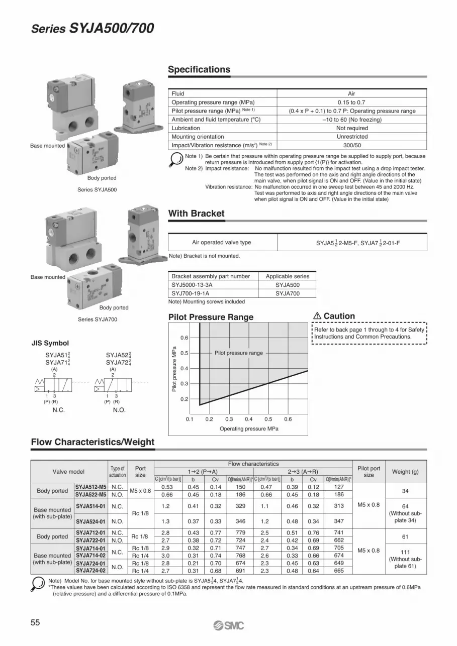
Flow Characteristics/Weight
SYJA512-M5
SYJA522-M5
SYJA514-01
SYJA524-01
C [dm3/(s bar)] b Cv C [dm3/(s bar)] b Cv1�2 (P�A) 2�3 (A�R)Valve model Weight (g)Pilot port
sizeType of
actuationPortsize
M5 x 0.8
M5 x 0.8
34
64(Without sub-
plate 34)Rc 1/8
N.C. 0.530.66
1.2
1.3
2.82.72.93.02.82.7
0.450.45
0.41
0.37
0.430.380.320.310.210.31
0.140.18
0.32
0.33
0.770.720.710.740.700.68
0.470.66
1.1
1.2
2.52.42.72.62.32.3
0.390.45
0.46
0.48
0.510.420.340.330.450.48
0.120.18
0.32
0.34
0.760.690.690.660.630.64
N.O.
N.C.
N.O.
Body ported
Base mounted(with sub-plate)
Specifications
FluidOperating pressure range (MPa)Pilot pressure range (MPa) Note 1)
Ambient and fluid temperature (ºC)LubricationMounting orientationImpact/Vibration resistance (m/s2) Note 2)
Air0.15 to 0.7
(0.4 x P + 0.1) to 0.7 P: Operating pressure range–10 to 60 (No freezing)
Not requiredUnrestricted
300/50
With Bracket
Air operated valve type SYJA5 2-M5-F, SYJA7 2-01-F12
12
Note) Bracket is not mounted.
Pilot Pressure Range
0.6
0.5
0.4
0.3
0.2
0.1 0.2 0.3 0.4 0.5 0.6Operating pressure MPa
Pilo
t pre
ssur
e M
Pa
JIS Symbol
SYJA51SYJA71
24 SYJA52
SYJA7224
N.C. N.O.
24
24
Series SYJA500
Series SYJA700
Body ported
Body ported
(A)2
1(P)
3(R)
(A)2
1(P)
3(R)
Base mounted
Base mounted
Note) Model No. for base mounted style without sub-plate is SYJA5 4, SYJA7 4.*These values have been calculated according to ISO 6358 and represent the flow rate measured in standard conditions at an upstream pressure of 0.6MPa (relative pressure) and a differential pressure of 0.1MPa.
12
12
SYJA712-01
SYJA722-01
SYJA714-01
SYJA714-02
SYJA724-01
SYJA724-02
Rc 1/8
Rc 1/8Rc 1/4Rc 1/8Rc 1/4
M5 x 0.8
61
111(Without sub-
plate 61)
N.C.N.O.
N.C.
N.O.
Body ported
Base mounted(with sub-plate)
Flow characteristics
55
Series SYJA500/700
Note 1) Be certain that pressure within operating pressure range be supplied to supply port, because return pressure is introduced from supply port {1(P)} for activation.
Note 2) Impact resistance: No malfunction resulted from the impact test using a drop impact tester. The test was performed on the axis and right angle directions of the main valve, when pilot signal is ON and OFF. (Value in the initial state)
Vibration resistance: No malfunction occurred in one sweep test between 45 and 2000 Hz.Test was performed to axis and right angle directions of the main valve when pilot signal is ON and OFF. (Value in the initial state)
Refer to back page 1 through to 4 for SafetyInstructions and Common Precautions.
Caution
Pilot pressure range
Q[l/min(ANR)]*150186
329
346
779724747768674691
Q[l/min(ANR)]*127186
313
347
741662705674649665
Bracket assembly part numberSYJ5000-13-3ASYJ700-19-1A
Applicable seriesSYJA500SYJA700
Note) Mounting screws included
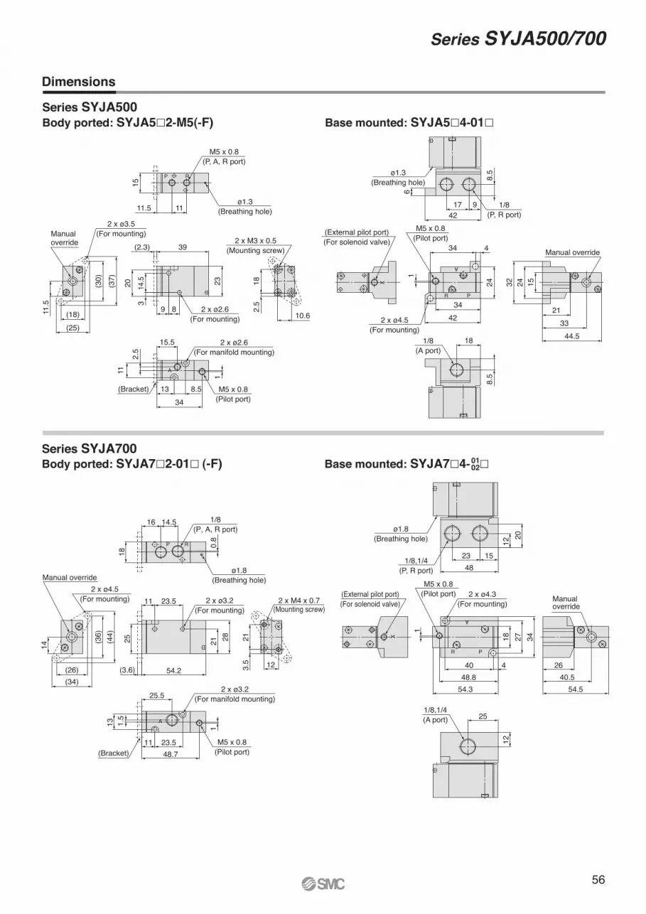
Series SYJA500/700
Dimensions
Series SYJA500
Body ported: SYJA7�2-01� (-F)
Body ported: SYJA5�2-M5(-F)
Series SYJA700Base mounted: SYJA7�4- �
Base mounted: SYJA5�4-01�
0102
56
44.533
21
32 24 15
Manual override
(External pilot port)(For solenoid valve)
X
18
8.5
1/8(A port)
8.5
6
4217 9
ø1.3(Breathing hole)
1/8(P, R port)
1
4234
24
434
2 x ø4.5(For mounting)
M5 x 0.8(Pilot port)
A
PR
11.5
(37)
(30)
(25)(18)
Manualoverride
2 x ø3.5(For mounting)
2.5
18
10.6
2 x M3 x 0.5(Mounting screw)
15
11.5 11ø1.3
(Breathing hole)
M5 x 0.8(P, A, R port)
RP
348.513
15.5
11
2.5
1
(Bracket)
2 x ø2.6(For manifold mounting)
M5 x 0.8(Pilot port)
A
2320 14.5
3
89
39(2.3)
2 x ø2.6(For mounting)
14
(34)(26)
(44)
(36)
2 x ø4.5(For mounting)
Manual override
123.5
21
2 x M4 x 0.7(Mounting screw)
(3.6)
28
11
21
54.2
25
23.5 2 x ø3.2(For mounting)
18
0.8
14.516
ø1.8(Breathing hole)
1/8(P, A, R port)
RP
13 1.5
25.5
23.51148.7
1
(Bracket)
2 x ø3.2(For manifold mounting)
M5 x 0.8(Pilot port)
A
1
54.3
4048.8
4
342718
2 x ø4.3(For mounting)
M5 x 0.8(Pilot port)
A
R P
54.540.5
26
Manual override
12
251/8,1/4(A port)
4823 15
2012
ø1.8(Breathing hole)
1/8,1/4(P, R port)
X
(External pilot port)(For solenoid valve)
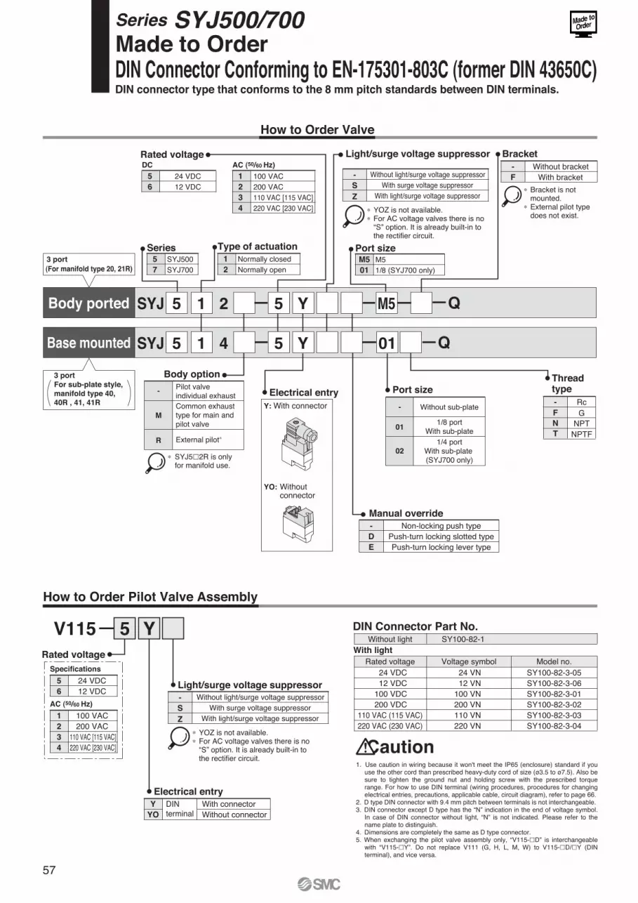
Series SYJ500/700Made to Order DIN Connector Conforming to EN-175301-803C (former DIN 43650C)DIN connector type that conforms to the 8 mm pitch standards between DIN terminals.
57
How to Order Valve
SYJ 2 5 Y M5
SYJ 4 5 Y 01
15
5 1
1
2
Normally closedNormally open
Type of actuation
5
7
SYJ500SYJ700
SeriesM5
01
M5 1/8 (SYJ700 only)
Port size
5
6
24 VDC12 VDC
Rated voltageDC
1
2
3
4
100 VAC 200 VAC 110 VAC [115 VAC] 220 VAC [230 VAC]
AC (50/60 Hz)
3 port
(For manifold type 20, 21R)
Body option
-
∗ SYJ5�2R is only for manifold use.
Bracket
Port size
How to Order Pilot Valve Assembly
- Without light/surge voltage suppressorS
Z
With surge voltage suppressorWith light/surge voltage suppressor
∗ YOZ is not available.∗ For AC voltage valves there is no “S” option. It is already built-in to the rectifier circuit.
Light/surge voltage suppressor
Body ported
Base mounted
∗ Bracket is not mounted.∗ External pilot type does not exist.
Rc
NPTNPTF
G
Thread type
N
T
F
-Y: With connector
YO: Without connector
Electrical entry
5 YV115
DINterminal
Y With connectorYO Without connector
- Without light/surge voltage suppressorS
Z
With surge voltage suppressorWith light/surge voltage suppressor
∗ YOZ is not available.∗ For AC voltage valves there is no “S” option. It is already built-in to the rectifier circuit.
Light/surge voltage suppressor
Electrical entry
5 24 VDC6 12 VDC
Specifications
1 100 VAC2 200 VAC3 110 VAC [115 VAC]4 220 VAC [230 VAC]
Rated voltage
AC (50/60 Hz)
Without lightWith light
SY100-82-1
Rated voltage Voltage symbol Model no.24 VDC 24 VN SY100-82-3-0512 VDC 12 VN SY100-82-3-06
100 VDC 100 VN SY100-82-3-01200 VDC 200 VN SY100-82-3-02
110 VAC (115 VAC) 110 VN SY100-82-3-03220 VAC (230 VAC) 220 VN SY100-82-3-04
- Non-locking push typeD Push-turn locking slotted typeE Push-turn locking lever type
Manual override
DIN Connector Part No.
Caution1. Use caution in wiring because it won't meet the IP65 (enclosure) standard if you
use the other cord than prescribed heavy-duty cord of size (ø3.5 to ø7.5). Also be sure to tighten the ground nut and holding screw with the prescribed torque range. For how to use DIN terminal (wiring procedures, procedures for changing electrical entries, precautions, applicable cable, circuit diagram), refer to page 66.
2. D type DIN connector with 9.4 mm pitch between terminals is not interchangeable.3. DIN connector except D type has the “N” indication in the end of voltage symbol.
In case of DIN connector without light, “N” is not indicated. Please refer to the name plate to distinguish.
4. Dimensions are completely the same as D type connector.5. When exchanging the pilot valve assembly only, “V115-�D” is interchangeable
with “V115-�Y”. Do not replace V111 (G, H, L, M, W) to V115-�D/�Y (DIN terminal), and vice versa.
Pilot valve individual exhaust
M
Common exhaust type for main and pilot valve
R External pilot∗
- Without sub-plate
011/8 port
With sub-plate
02
1/4 portWith sub-plate (SYJ700 only)
- Without bracketF With bracket
For sub-plate style,
manifold type 40,
40R , 41, 41R
3 port
Q
Q
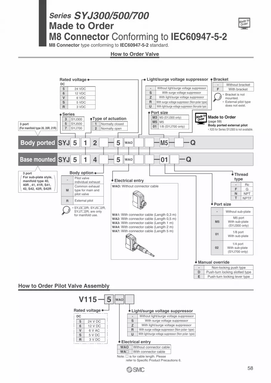
Series SYJ300/500/700Made to Order M8 Connector Conforming to IEC60947-5-2M8 Connector type conforming to IEC60947-5-2 standard.
58
How to Order Valve
SYJ 2 5 WAO M5
SYJ 4 5 01
15
5 1
12
Normally closed
Normally open
Type of actuation357
SYJ300
SYJ500
SYJ700
SeriesM3M501
M3 (SYJ300 only)
M5
1/8 (SYJ700 only)
Port size
56VSR
24 VDC
12 VDC
6 VDC
5 VDC
3 VDC
Rated voltageDC
3 port(For manifold type 20, 20R, 21R)
Body option
-
∗ SYJ3�2R, SYJ5�2R, SYJ7�2R, are only for manifold use.
Bracket
Port size
How to Order Pilot Valve Assembly
- Without light/surge voltage suppressor
S
Z
With surge voltage suppressor
With light/surge voltage suppressor
Light/surge voltage suppressor
Body ported
Base mounted
∗ Bracket is not mounted.∗ External pilot type does not exist.
Rc
NPTNPTF
G
Thread type
NT
F-WAO: Without connector cable
WA1: With connector cable (Length 0,3 m)WA2: With connector cable (Length 0,5 m)WA3: With connector cable (Length 1 m)WA4: With connector cable (Length 2 m)WA7: With connector cable (Length 5 m)
Electrical entry
5V115
WAO Without connector cableWA� With connector cable
- Without light/surge voltage suppressor
S
Z
With surge voltage suppressor
With light/surge voltage suppressor
Light/surge voltage suppressor
Electrical entry
5 24 V DC6 12 V DCV 6 V ACS 5 V DCR 3 V DC
Rated voltage
DC
- Non-locking push typeD Push-turn locking slotted typeE Push-turn locking lever type
Manual override
Pilot valve individual exhaust
MCommon exhaust type for main and pilot valve
R External pilot
- Without sub-plate
011/8 port
With sub-plate
021/4 port
With sub-plate (SYJ700 only)
- Without bracketF With bracket
For sub-plate style, manifold type 40, 40R , 41, 41R, S41,42, S42, 42R, S42R
3 port
Q
QWAO
RU
With surge voltage suppressor (Non-polar type)
With light/surge voltage suppressor (Non-polar type)
M5M5 port
With sub-plate (SYJ300 only)
WAO
R
U
With surge voltage suppressor (Non polar- type)
With light/surge voltage suppressor (Non polar- type)
Note: � is for cable length. Please refer to Specific Product Precautions 6.
Made to Order(page 59)Body ported external pilot∗ X20 for Series SYJ300 is not available.
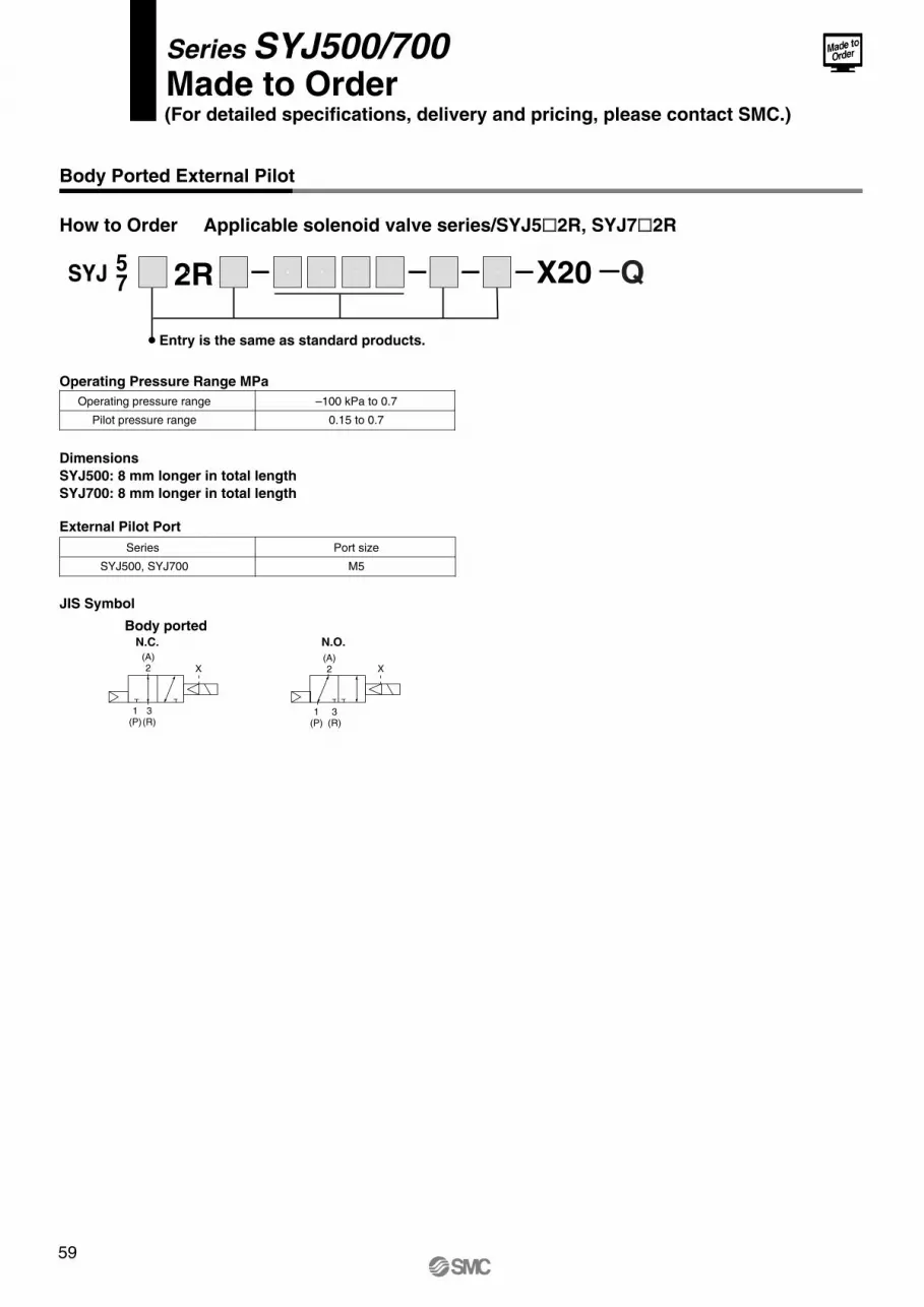
Body Ported External Pilot
(For detailed specifications, delivery and pricing, please contact SMC.)
Series SYJ500/700Made to Order
Operating Pressure Range MPa
Operating pressure range
Pilot pressure range
–100 kPa to 0.7
0.15 to 0.7
How to Order Applicable solenoid valve series/SYJ5�2R, SYJ7�2R
SYJ 57 2R X20
Entry is the same as standard products.
External Pilot Port
DimensionsSYJ500: 8 mm longer in total lengthSYJ700: 8 mm longer in total length
JIS Symbol
Body portedN.C. N.O.
Series
SYJ500, SYJ700
Port size
M5
X X(A)2
1(P)
3(R)
(A)2
1(P)
3(R)
59
Q

60
� �
Back page 1
Safety InstructionsSeries SYJ
These safety instructions are intended to prevent a hazardous situation and/or equipment damage. These instructions indicate the level of potential hazard by labels of "Caution", "Warning" or "Danger". To ensure safety, be sure to observe ISO 4414 Note 1), JIS B 8370 Note 2) and other safety practices.
1. The compatibility of pneumatic equipment is the responsibility of the person who designs the pneumatic system or decides its specifications.Since the products specified here are used in various operating conditions, their compatibility for the
specific pneumatic system must be based on specifications or after analysis and/or tests to meet your
specific requirements. The expected performance and safety assurance will be the responsibility of the
person who has determined the compatibility of the system. This person should continuously review
the suitability of all items specified, referring to the latest catalogue information with a view to giving
due consideration to any possibility of equipment failure when configuring a system.
2. Only trained personnel should operate pneumatically operated machinery and equipment.Compressed air can be dangerous if an operator is unfamiliar with it. Assembly, handling or repair of
pneumatic systems should be performed by trained and experienced operators.
3. Do not service machinery/equipment or attempt to remove components until safety is confirmed.1. Inspection and maintenance of machinery/equipment should only be performed once measures to
prevent falling or runaway of the driver objects have been confirmed.
2. When equipment is to be removed, confirm the safety process as mentioned above. Cut the supply
pressure for this equipment and exhaust all residual compressed air in the system.
3. Before machinery/equipment is restarted, take measures to prevent shooting-out of cylinder piston
rod, etc.
4. Contact SMC if the product is to be used in any of the following conditions:1. Conditions and environments beyond the given specifications, or if product is used outdoors.
2. Installation on equipment in conjunction with atomic energy, railway, air navigation, vehicles,
medical equipment, food and beverages, recreation equipment, emergency stop circuits, clutch and
brake circuits in press applications, or safety equipment.
3. An application which has the possibility of having negative effects on people, property, or animals,
requiring special safety analysis.
Note 1) ISO 4414: Pneumatic fluid power--General rules relating to systems.
Note 2) JIS B 8370: General Rules for Pneumatic Equipment
Warning
Caution : Operator error could result in injury or equipment damage.
Warning : Operator error could result in serious injury or loss of life.
Danger : In extreme conditions, there is a possible result of serious injury or loss of life.
Design
Selection
Selection
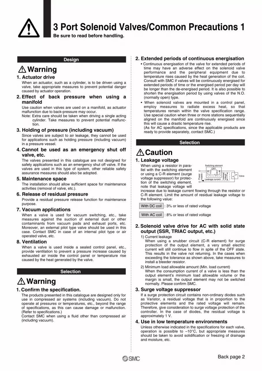
1. Actuator driveWhen an actuator, such as a cylinder, is to be driven using a valve, take appropriate measures to prevent potential danger caused by actuator operation.
2. Effect of back pressure when using a manifoldUse caution when valves are used on a manifold, as actuator malfunction due to back-pressure may occur.Note: Extra care should be taken when driving a single acting
cylinder. Take measures to prevent potential malfunc-tion.
3. Holding of pressure (including vacuum)Since valves are subject to air leakage, they cannot be used for applications such as holding pressure (including vacuum) in a pressure vessel.
4. Cannot be used as an emergency shut off valve, etc.The valves presented in this catalogue are not designed for safety applications such as an emergency shut off valve. If the valves are used in this type of system, other reliable safety assurance measures should also be adopted.
5. Maintenance space The installation should allow sufficient space for maintenance activities (removal of valve, etc.).
6. Release of residual pressureProvide a residual pressure release function for maintenance purpose.
7. Vacuum applicationsWhen a valve is used for vacuum switching, etc., take measures against the suction of external dust or other contaminants from vacuum pads and exhaust ports, etc. Moreover, an external pilot type valve should be used in this case. Contact SMC in case of an internal pilot type or air operated valve, etc.
8. VentilationWhen a valve is used inside a sealed control panel, etc., provide ventilation to prevent a pressure increase caused by exhausted air inside the control panel or temperature rise caused by the heat generated by the valve.
Design
Selection
1. Confirm the specification.The products presented in this catalogue are designed only for use in compressed air systems (including vacuum). Do not operate at pressures or temperatures, etc., beyond the range of specifications, as this can cause damage or malfunction. (Refer to specifications.)Contact SMC when using a fluid other than compressed air (including vacuum).
2. Extended periods of continuous energisation• Continuous energisation of the valve for extended periods of
time may have an adverse effect on the solenoid valve performance and the peripheral equipment due to temperature rises caused by the heat generation of the coil. Consult with SMC if valves will be continuously energised for extended periods of time or the energised period per day will be longer than the de-energised period. It is also possible to shorten the energisation period by using valves of the N.O. (normally open) type.
• When solenoid valves are mounted in a control panel, employ measures to radiate excess heat, so that temperatures remain within the valve specification range. Use special caution when three or more stations sequentially aligned on the manifold are continuously energised since this will cause a drastic temperature rise.(As for AC specifications, since the applicable products are ready to provide separately, contact SMC.)
Warning
Warning
Back page 2
3 Port Solenoid Valves/Common Precautions 1Be sure to read before handling.
Selection
With DC coil : 3% or less of rated voltage
With AC coil : 8% or less of rated voltage
Caution
Switching element
C
OFF
Leakage current
Valve
R
Leak
age
volta
ge
Po
we
r su
pp
ly
1. Leakage voltageWhen using a resistor in para-llel with the switching element or using a C-R element (surge voltage suppressor) for protec-tion of the switching element, note that leakage voltage will increase due to leakage current flowing through the resistor or C-R element. Limit the amount of residual leakage voltage to the following value:
2. Solenoid valve drive for AC with solid state output (SSR, TRIAC output, etc.) 1) Current leakage
When using a snubber circuit (C-R element) for surge protection of the output element, a very small electric current will still continue to flow in spite of the OFF state. This results in the valve not returning. In the cases when exceeding the tolerance as shown above, take measures to install a bleeder resistor.
2) Minimum load allowable amount (Min. load current)When the consumption current of a valve is less than the output element’s minimum load allowable volume or the margin is small, the output element may not be switched normally. Please confirm SMC.
3. Surge voltage suppressorIf a surge protection circuit contains non-ordinary diodes such as Varistor, a residual voltage that is in proportion to the protective elements and the rated voltage will remain. Therefore, give consideration to surge voltage protection of the controller. In the case of diodes, the residual voltage is approximately 1 V.
4. Use in low temperature environmentsUnless otherwise indicated in the specifications for each valve, operation is possible to –10°C, but appropriate measures should be taken to avoid solidification or freezing of drainage and moisture, etc.
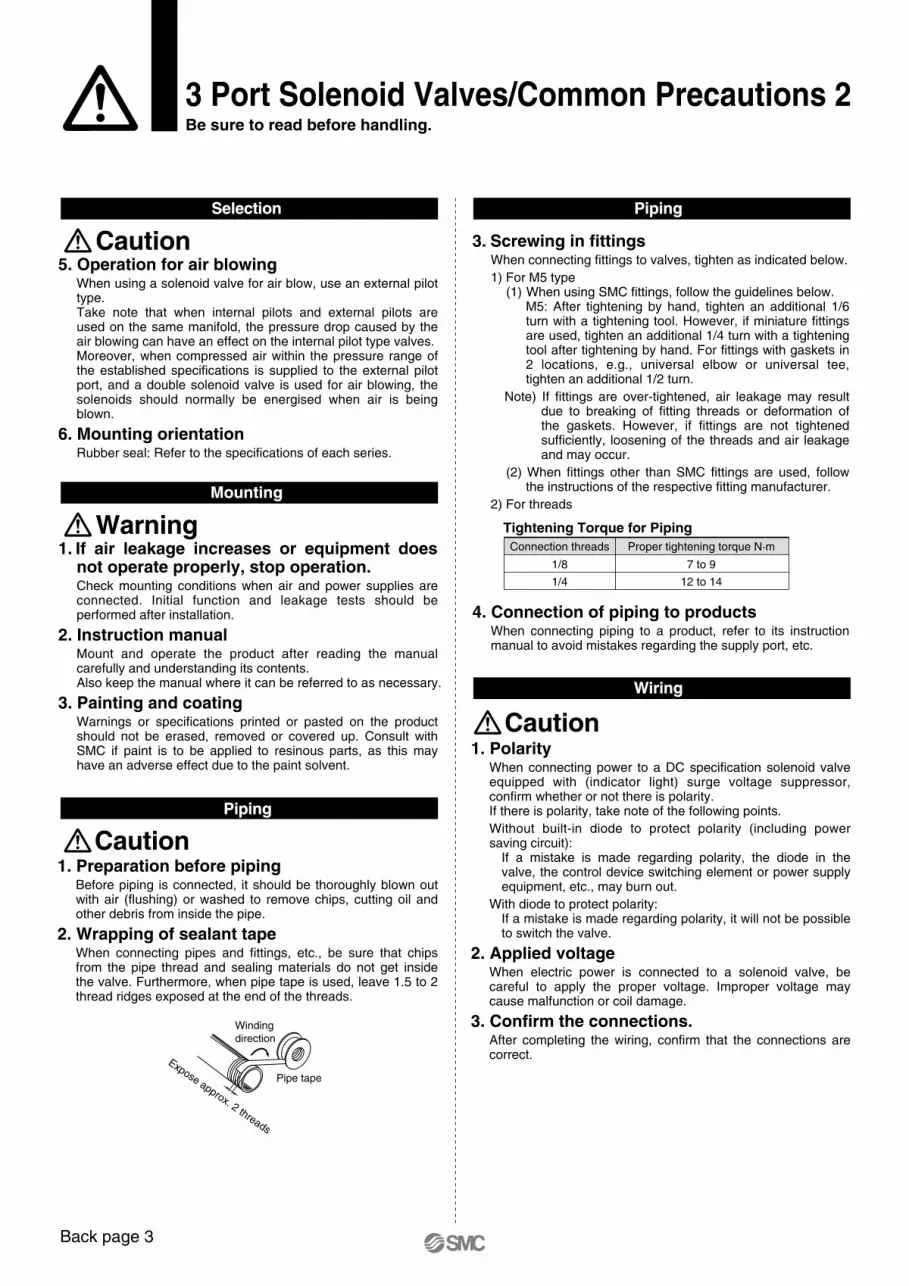
Back page 3
3 Port Solenoid Valves/Common Precautions 2Be sure to read before handling.
1. If air leakage increases or equipment does not operate properly, stop operation.Check mounting conditions when air and power supplies are connected. Initial function and leakage tests should be performed after installation.
2. Instruction manual Mount and operate the product after reading the manual carefully and understanding its contents. Also keep the manual where it can be referred to as necessary.
3. Painting and coatingWarnings or specifications printed or pasted on the product should not be erased, removed or covered up. Consult with SMC if paint is to be applied to resinous parts, as this may have an adverse effect due to the paint solvent.
Mounting
1. Preparation before pipingBefore piping is connected, it should be thoroughly blown out with air (flushing) or washed to remove chips, cutting oil and other debris from inside the pipe.
2. Wrapping of sealant tapeWhen connecting pipes and fittings, etc., be sure that chips from the pipe thread and sealing materials do not get inside the valve. Furthermore, when pipe tape is used, leave 1.5 to 2 thread ridges exposed at the end of the threads.
Piping
Windingdirection
Pipe tape
Expose approx. 2 threads
Warning
5. Operation for air blowingWhen using a solenoid valve for air blow, use an external pilot type. Take note that when internal pilots and external pilots are used on the same manifold, the pressure drop caused by the air blowing can have an effect on the internal pilot type valves.Moreover, when compressed air within the pressure range of the established specifications is supplied to the external pilot port, and a double solenoid valve is used for air blowing, the solenoids should normally be energised when air is being blown.
6. Mounting orientation Rubber seal: Refer to the specifications of each series.
Selection
Caution
Caution
3. Screwing in fittingsWhen connecting fittings to valves, tighten as indicated below.
1) For M5 type(1) When using SMC fittings, follow the guidelines below.
M5: After tightening by hand, tighten an additional 1/6 turn with a tightening tool. However, if miniature fittings are used, tighten an additional 1/4 turn with a tightening tool after tightening by hand. For fittings with gaskets in 2 locations, e.g., universal elbow or universal tee, tighten an additional 1/2 turn.
Note) If fittings are over-tightened, air leakage may result due to breaking of fitting threads or deformation of the gaskets. However, if fittings are not tightened sufficiently, loosening of the threads and air leakage and may occur.
(2) When fittings other than SMC fittings are used, follow the instructions of the respective fitting manufacturer.
2) For threads
1. Polarity When connecting power to a DC specification solenoid valve equipped with (indicator light) surge voltage suppressor, confirm whether or not there is polarity.If there is polarity, take note of the following points.
Without built-in diode to protect polarity (including power saving circuit):
If a mistake is made regarding polarity, the diode in the valve, the control device switching element or power supply equipment, etc., may burn out.
With diode to protect polarity:If a mistake is made regarding polarity, it will not be possible to switch the valve.
2. Applied voltageWhen electric power is connected to a solenoid valve, be careful to apply the proper voltage. Improper voltage may cause malfunction or coil damage.
3. Confirm the connections.After completing the wiring, confirm that the connections are correct.
Wiring
Caution
Piping
4. Connection of piping to productsWhen connecting piping to a product, refer to its instruction manual to avoid mistakes regarding the supply port, etc.
Tightening Torque for PipingConnection threads
1/8
1/4
7 to 9
12 to 14
Proper tightening torque N·m
Operating Environment
Maintenance
Operating Environment
Air Supply
Lubrication
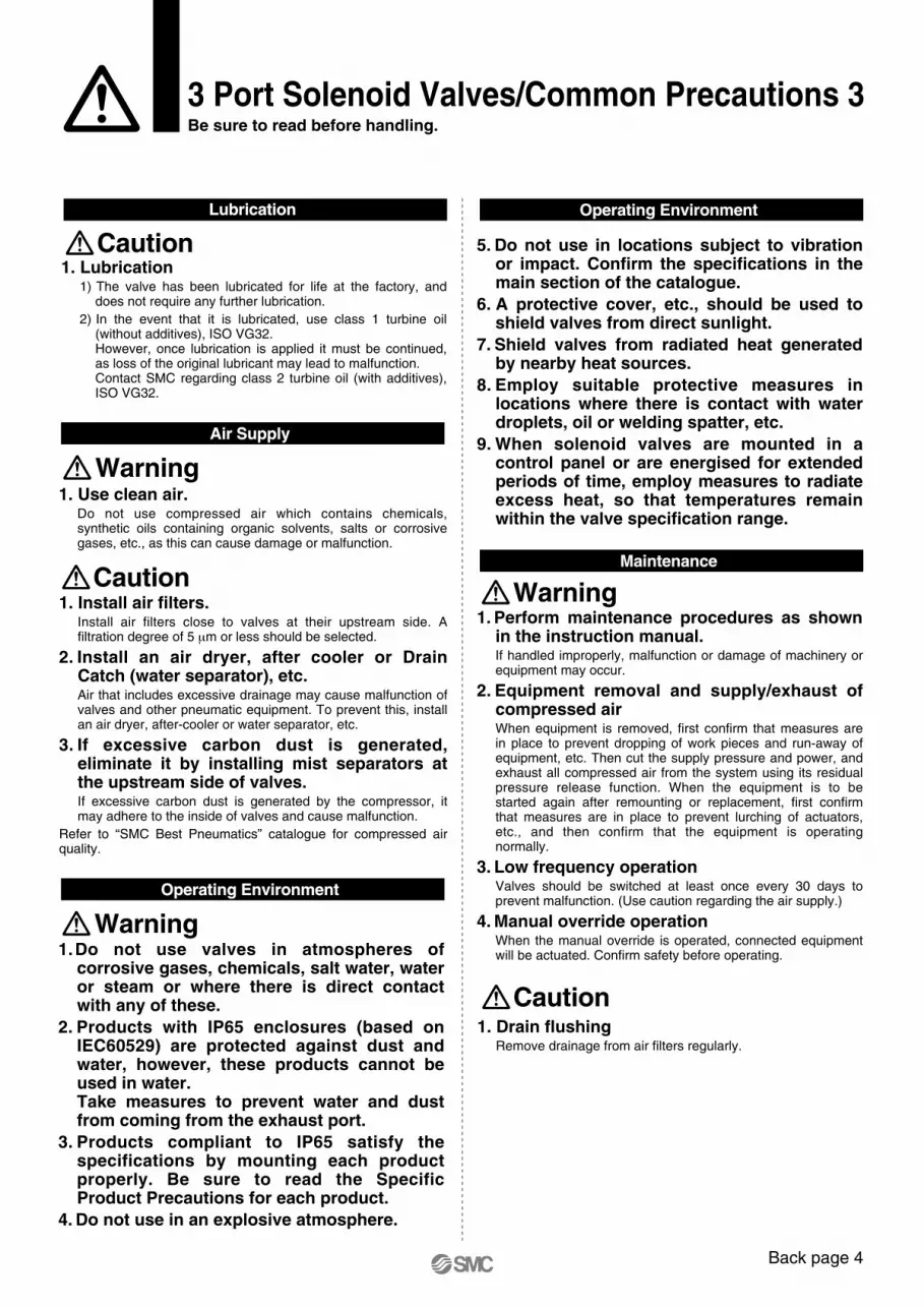
Mounting
Piping
Selection
Wiring
Piping
3 Port Solenoid Valves/Common Precautions 3Be sure to read before handling.
1. Drain flushingRemove drainage from air filters regularly.
1.Do not use valves in atmospheres of corrosive gases, chemicals, salt water, water or steam or where there is direct contact with any of these.
2. Products with IP65 enclosures (based on IEC60529) are protected against dust and water, however, these products cannot be used in water.Take measures to prevent water and dust from coming from the exhaust port.
3. Products compliant to IP65 satisfy the specifications by mounting each product properly. Be sure to read the Specific Product Precautions for each product.
4. Do not use in an explosive atmosphere.
Operating Environment
Warning
1. Perform maintenance procedures as shown in the instruction manual. If handled improperly, malfunction or damage of machinery or equipment may occur.
2. Equipment removal and supply/exhaust of compressed air When equipment is removed, first confirm that measures are in place to prevent dropping of work pieces and run-away of equipment, etc. Then cut the supply pressure and power, and exhaust all compressed air from the system using its residual pressure release function. When the equipment is to be started again after remounting or replacement, first confirm that measures are in place to prevent lurching of actuators, etc., and then confirm that the equipment is operating normally.
3. Low frequency operationValves should be switched at least once every 30 days to prevent malfunction. (Use caution regarding the air supply.)
4. Manual override operationWhen the manual override is operated, connected equipment will be actuated. Confirm safety before operating.
Maintenance
Warning
5. Do not use in locations subject to vibration or impact. Confirm the specifications in the main section of the catalogue.
6. A protective cover, etc., should be used to shield valves from direct sunlight.
7. Shield valves from radiated heat generated by nearby heat sources.
8. Employ suitable protective measures in locations where there is contact with water droplets, oil or welding spatter, etc.
9. When solenoid valves are mounted in a control panel or are energised for extended periods of time, employ measures to radiate excess heat, so that temperatures remain within the valve specification range.
Operating Environment
Caution
1. Use clean air.Do not use compressed air which contains chemicals, synthetic oils containing organic solvents, salts or corrosive gases, etc., as this can cause damage or malfunction.
1. Install air filters.Install air filters close to valves at their upstream side. A filtration degree of 5 μm or less should be selected.
2. Install an air dryer, after cooler or Drain Catch (water separator), etc.Air that includes excessive drainage may cause malfunction of valves and other pneumatic equipment. To prevent this, install an air dryer, after-cooler or water separator, etc.
3. If excessive carbon dust is generated, eliminate it by installing mist separators at the upstream side of valves.If excessive carbon dust is generated by the compressor, it may adhere to the inside of valves and cause malfunction.
Refer to “SMC Best Pneumatics” catalogue for compressed air quality.
Air Supply
Warning
Caution
Back page 4
Lubrication
1. Lubrication1) The valve has been lubricated for life at the factory, and
does not require any further lubrication.
2) In the event that it is lubricated, use class 1 turbine oil (without additives), ISO VG32.However, once lubrication is applied it must be continued, as loss of the original lubricant may lead to malfunction.Contact SMC regarding class 2 turbine oil (with additives), ISO VG32.
Caution
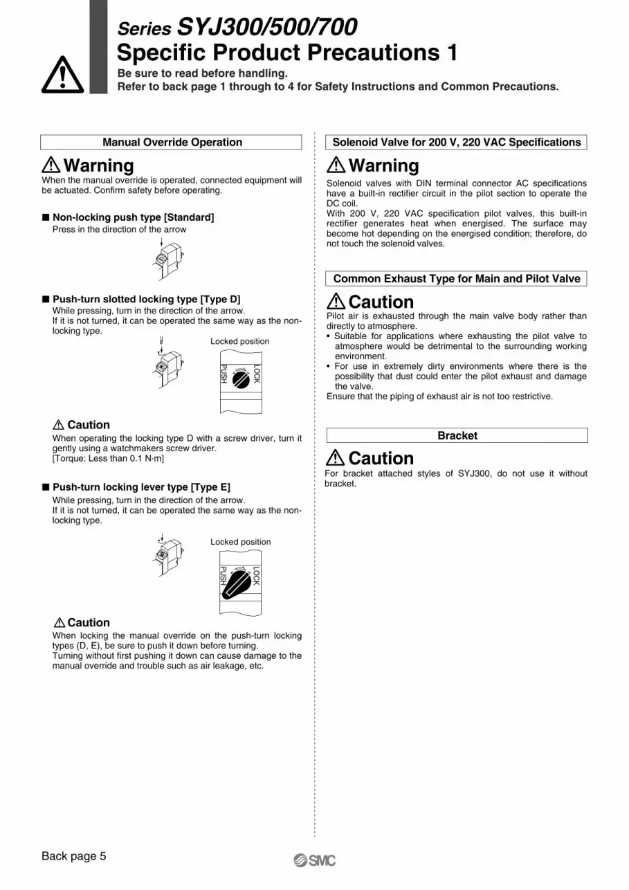
Back page 5
� Non-locking push type [Standard]Press in the direction of the arrow
Series SYJ300/500/700Specific Product Precautions 1Be sure to read before handling.Refer to back page 1 through to 4 for Safety Instructions and Common Precautions.
� Push-turn slotted locking type [Type D]
Locked position
� Push-turn locking lever type [Type E]
Locked position
PU
SH
LOC
K
Caution
Solenoid valves with DIN terminal connector AC specifications have a built-in rectifier circuit in the pilot section to operate the DC coil.With 200 V, 220 VAC specification pilot valves, this built-in rectifier generates heat when energised. The surface may become hot depending on the energised condition; therefore, do not touch the solenoid valves.
Manual Override Operation
Warning
While pressing, turn in the direction of the arrow.If it is not turned, it can be operated the same way as the non-locking type.
When operating the locking type D with a screw driver, turn it gently using a watchmakers screw driver.[Torque: Less than 0.1 N.m]
While pressing, turn in the direction of the arrow.If it is not turned, it can be operated the same way as the non-locking type.
When the manual override is operated, connected equipment will be actuated. Confirm safety before operating.
Caution
When locking the manual override on the push-turn locking types (D, E), be sure to push it down before turning.Turning without first pushing it down can cause damage to the manual override and trouble such as air leakage, etc.
Solenoid Valve for 200 V, 220 VAC Specifications
Warning
Pilot air is exhausted through the main valve body rather than directly to atmosphere.• Suitable for applications where exhausting the pilot valve to
atmosphere would be detrimental to the surrounding working environment.
• For use in extremely dirty environments where there is the possibility that dust could enter the pilot exhaust and damage the valve.
Ensure that the piping of exhaust air is not too restrictive.
Common Exhaust Type for Main and Pilot Valve
Caution
Bracket
For bracket attached styles of SYJ300, do not use it without bracket.
Caution
PU
SH
LOC
K
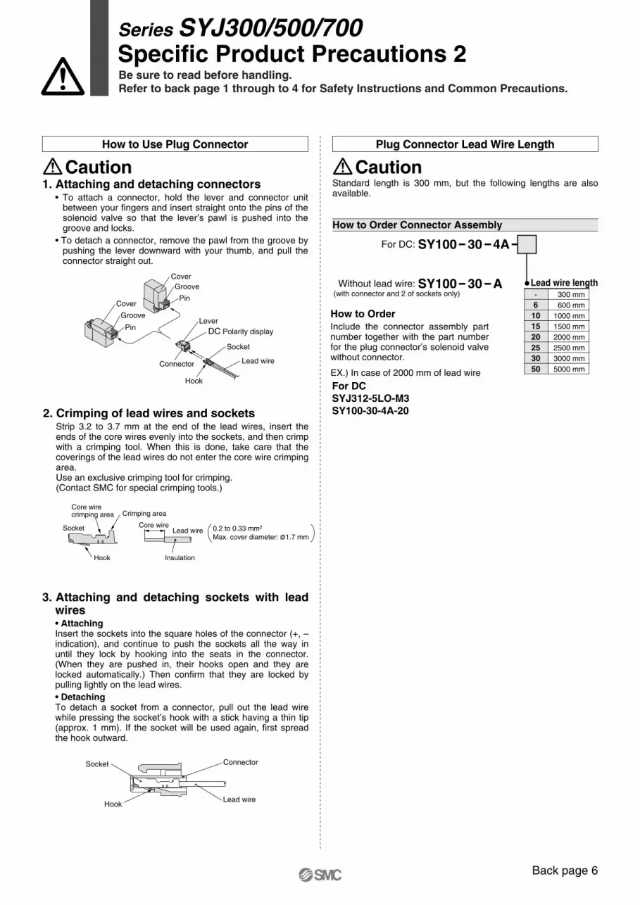
Back page 6
3. Attaching and detaching sockets with lead wires• Attaching Insert the sockets into the square holes of the connector (+, – indication), and continue to push the sockets all the way in until they lock by hooking into the seats in the connector. (When they are pushed in, their hooks open and they are locked automatically.) Then confirm that they are locked by pulling lightly on the lead wires.
• DetachingTo detach a socket from a connector, pull out the lead wire while pressing the socket’s hook with a stick having a thin tip (approx. 1 mm). If the socket will be used again, first spread the hook outward.
Series SYJ300/500/700Specific Product Precautions 2Be sure to read before handling.Refer to back page 1 through to 4 for Safety Instructions and Common Precautions.
How to Order Connector Assembly
For DC: SY100 30 4A
Without lead wire: SY100 30 A Lead wire length-
6101520253050
300 mm
600 mm
1000 mm
1500 mm
2000 mm
2500 mm
3000 mm
5000 mm
For DCSYJ312-5LO-M3SY100-30-4A-20
(with connector and 2 of sockets only)
How to Order Include the connector assembly part number together with the part number for the plug connector’s solenoid valve without connector.
EX.) In case of 2000 mm of lead wire
Connector
Lead wire
Socket
Hook
Lead wire Socket
Crimping areaCore wire crimping area
Hook Insulation
0.2 to 0.33 mm2 Max. cover diameter: ø1.7 mm
Core wire
2. Crimping of lead wires and sockets Strip 3.2 to 3.7 mm at the end of the lead wires, insert the ends of the core wires evenly into the sockets, and then crimp with a crimping tool. When this is done, take care that the coverings of the lead wires do not enter the core wire crimping area.Use an exclusive crimping tool for crimping.(Contact SMC for special crimping tools.)
Socket
Hook
Lead wire
DC Polarity display
Lever
Connector
Pin
GrooveCover
Pin
Groove
Cover
-+
1. Attaching and detaching connectors• To attach a connector, hold the lever and connector unit
between your fingers and insert straight onto the pins of the solenoid valve so that the lever’s pawl is pushed into the groove and locks.
• To detach a connector, remove the pawl from the groove by pushing the lever downward with your thumb, and pull the connector straight out.
Caution
How to Use Plug Connector
Standard length is 300 mm, but the following lengths are also available.
Caution
Plug Connector Lead Wire Length
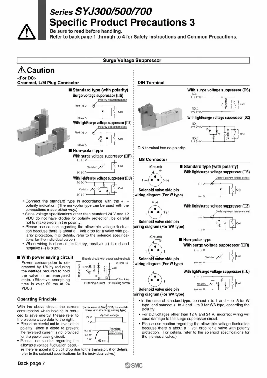
Back page 7
Series SYJ300/500/700Specific Product Precautions 3Be sure to read before handling.Refer to back page 1 through to 4 for Safety Instructions and Common Precautions.
With surge voltage suppressor (DS)
With light/surge voltage suppressor (DZ)
DIN Terminal
DIN terminal has no polarity.
<For DC> Grommet, L/M Plug Connector
� Standard type (with polarity)Surge voltage suppressor (�S)
Red (+)
Black
Polarity protection diode
With light/surge voltage suppressor (�Z)
Red (+)
Black
Polarity protection diode
• Connect the standard type in accordance with the +, – polarity indication. (The non-polar type can be used with the connections made either way.)
• Since voltage specifications other than standard 24 V and 12 VDC do not have diodes for polarity protection, be careful not to make errors in the polarity.
• Please use caution regarding the allowable voltage fluctua-tion because there is about a 1 volt drop for a valve with po-larity protection. (For details, refer to the solenoid specifica-tions for the individual valve.)
• When wiring is done at the factory, positive (+) is red and negative (–) is black.
� Non-polar typeWith surge voltage suppressor (�R)
With light/surge voltage suppressor (�U)
(–) (+)
(+) (–)
Varistor
(–) (+)
(+) (–)
Varistor
Surge Voltage Suppressor
Caution
M8 Connector
Solenoid valve side pinwiring diagram (For W type)
Solenoid valve side pinwiring diagram (For WA type)
Solenoid valve side pinwiring diagram (For W type)
Solenoid valve side pinwiring diagram (For WA type)
With light/surge voltage suppressor (�U)
� Non-polar typeWith surge voltage suppressor (�R)
With light/surge voltage suppressor (�Z)
� Standard type (with polarity)With light/surge voltage suppressor (�S)
• In the case of standard type, connect + to 1 and – to 3 for W type, and connect + to 4 and - to 3 for WA type, according the polarity.
• For DC voltages other than 12 V and 24 V, incorrect wiring will case damage to the surge suppressor circuit.
• Please use caution regarding the allowable voltage fluctuation because there is about a 1 volt drop for a valve with polarity protection. (For details, refer to the solenoid specifications for the individual valve.)
(+)
(–)
Diode to prevent reverse current
(+)
(–)
Diode to prevent reverse current
(–) (+)
(+) (–)
Varistor
(–) (+)
(+) (–)
Varistor
Coil
Coil
Coil
Coil
Operating Principle
(In the case of SYJ ��T, the electric wave form of energy saving type)
357
Applied voltage
StandardWith power
saving circuit
62 ms
24 V
0 V
0.4 W
0.1 W
0 W
� With power saving circuit Electric circuit (with power saving circuit)
1: Starting current 2: Holding current
2
Red (+)
Black (–)
LED
1
Power consumption is de-creased by 1/4 by reducing the wattage required to hold the valve in an energised state. (Effective energising time is over 62 ms at 24 VDC.)
With the above circuit, the current consumption when holding is redu-ced to save energy. Please refer to the electric wave data to the right.• Please be careful not to reverse the
polarity, since a diode to prevent the reversed current is not provided for the power saving circuit.
• Please use caution regarding the allowable voltage fluctuation becau-se there is about a 0.5 volt drop due to the transistor. (For details, refer to the solenoid specifications for the individual valve.)
Coil
Dio
de
Tim
er
circ
uit
Va
rist
or
Va
rist
or
Coil
Coil
Coil
Coil
Coil
Coil
(Ground)
4
1
1 3
(Ground)
4
1 3
4
1 (+) 3 (–)
3 (–)
4 (+)
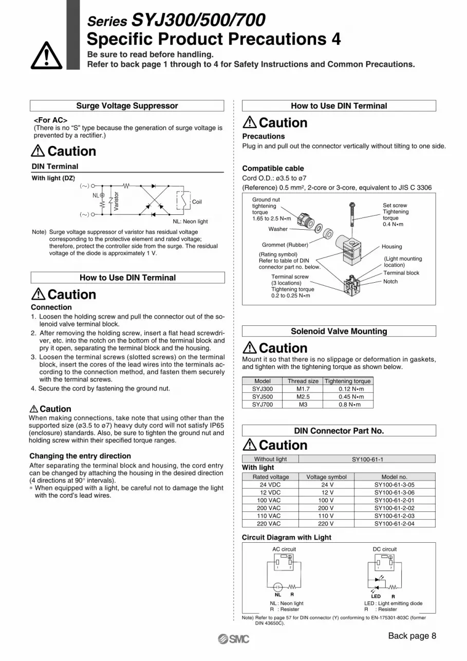
Series SYJ300/500/700Specific Product Precautions 4Be sure to read before handling.Refer to back page 1 through to 4 for Safety Instructions and Common Precautions.
Changing the entry direction
Compatible cable
Precautions Plug in and pull out the connector vertically without tilting to one side.
Cord O.D.: ø3.5 to ø7
(Reference) 0.5 mm2, 2-core or 3-core, equivalent to JIS C 3306
After separating the terminal block and housing, the cord entry can be changed by attaching the housing in the desired direction (4 directions at 90° intervals).∗ When equipped with a light, be careful not to damage the light
with the cord’s lead wires.
Circuit Diagram with Light
Note) Refer to page 57 for DIN connector (Y) conforming to EN-175301-803C (formerDIN 43650C).
Rated voltage24 VDC12 VDC
100 VAC200 VAC110 VAC220 VAC
Voltage symbol24 V12 V
100 V200 V110 V220 V
Model no.SY100-61-3-05SY100-61-3-06SY100-61-2-01SY100-61-2-02SY100-61-2-03SY100-61-2-04
Without light SY100-61-1
With light
Caution
How to Use DIN Terminal
Mount it so that there is no slippage or deformation in gaskets, and tighten with the tightening torque as shown below.
Caution
Solenoid Valve Mounting
CautionDIN Connector Part No.
When making connections, take note that using other than the supported size (ø3.5 to ø7) heavy duty cord will not satisfy IP65 (enclosure) standards. Also, be sure to tighten the ground nut and holding screw within their specified torque ranges.
Caution
Connection 1. Loosen the holding screw and pull the connector out of the so-
lenoid valve terminal block.
2. After removing the holding screw, insert a flat head screwdri-ver, etc. into the notch on the bottom of the terminal block and pry it open, separating the terminal block and the housing.
3. Loosen the terminal screws (slotted screws) on the terminal block, insert the cores of the lead wires into the terminals ac-cording to the connection method, and fasten them securely with the terminal screws.
4. Secure the cord by fastening the ground nut.
Caution
How to Use DIN Terminal
DIN Terminal
With light (DZ)
Note) Surge voltage suppressor of varistor has residual voltage corresponding to the protective element and rated voltage; therefore, protect the controller side from the surge. The residual voltage of the diode is approximately 1 V.
<For AC>(There is no “S” type because the generation of surge voltage is prevented by a rectifier.)
Surge Voltage Suppressor
Caution
ModelSYJ300SYJ500SYJ700
Thread sizeM1.7M2.5M3
Tightening torque0.12 N �m0.45 N �m0.8 N �m
Va
rist
or
Coil Ground nuttightening torque1.65 to 2.5 N �m
Washer
Grommet (Rubber)
(Rating symbol)Refer to table of DINconnector part no. below.
Terminal screw(3 locations)Tightening torque0.2 to 0.25 N �m
Set screwTightening torque0.4 N �m
Housing
(Light mountinglocation)
Terminal block
Notch
Back page 8
NL: Neon light
AC circuit
NL : Neon lightR : Resister
LED : Light emitting diodeR : Resister
DC circuit
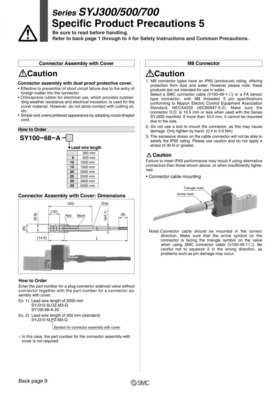
Back page 9
Series SYJ300/500/700Specific Product Precautions 5Be sure to read before handling.Refer to back page 1 through to 4 for Safety Instructions and Common Precautions.
1. M8 connector types have an IP65 (enclosure) rating, offering protection from dust and water. However please note: these products are not intended for use in water.Select a SMC connector cable (V100-49-1-�) or a FA sensor type connector, with M8 threaded 3 pin specifications conforming to Nippon Electric Control Equipment Association Standard, NECA4202 (IEC60947-5-2). Make sure the connector O.D. is 10.5 mm or less when used with the Series SYJ300 manifold. If more than 10.5 mm, it cannot be mounted due to the size.
2. Do not use a tool to mount the connector, as this may cause damage. Only tighten by hand. (0.4 to 0.6 Nm)
3. The excessive stress on the cable connector will not be able to satisfy the IP65 rating. Please use caution and do not apply a stress of 30 N or greater.
Failure to meet IP65 performance may result if using alternative connectors than those shown above, or when insufficiently tighte-ned.
Caution
• Connector cable mounting
Note) Connector cable should be mounted in the correct direction. Make sure that the arrow symbol on the connector is facing the triangle symbol on the valve when using SMC connector cable (V100-49-1-�). Be careful not to squeeze it in the wrong direction, as problems such as pin damage may occur.
M8 Connector
CautionConnector assembly with dust proof protective cover.• Effective to prevention of short circuit failure due to the entry of
foreign matter into the connector.• Chloroprene rubber for electrical use, which provides outstan-
ding weather resistance and electrical insulation, is used for the cover material. However, do not allow contact with cutting oil, etc.
• Simple and unencumbered appearance by adopting round-shaped cord.
Caution
Connector Assembly with Cover
-
101520253050
300 mm
1000 mm6 600 mm
1500 mm2000 mm2500 mm3000 mm5000 mm
Lead wire length
SY100-68-A
Connector Assembly with Cover: Dimensions
Red Black
Gray
(14.5) L
(40)
(10)(8)
(8)
(6.9
)
(ø4.1
)
How to Order
Symbol for connector assembly with cover
How to Order Enter the part number for a plug connector solenoid valve without connector together with the part number for a connector as-sembly with cover.
Ex. 1) Lead wire length of 2000 mm SYJ312-5LOZ-M3-Q SY100-68-A-20
Ex. 2) Lead wire length of 300 mm (standard) SYJ312-5LPZ-M3-Q
∗ In this case, the part number for the connector assembly with cover is not required.
Arrow mark
Triangle mark
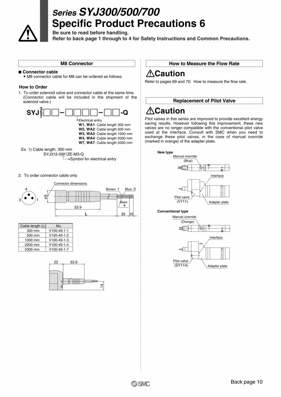
Back page 10
Refer to pages 69 and 70: How to measure the flow rate.
Series SYJ300/500/700Specific Product Precautions 6Be sure to read before handling.Refer to back page 1 through to 4 for Safety Instructions and Common Precautions.
New type
Conventional type
(Orange)
Manual override
(Blue)
Manual override
Interface
Pilot valve
(V111) Adapter plate
A B+-
A B+-
Interface
Pilot valve
(SY114) Adapter plate
How to Measure the Flow Rate
Caution
Pilot valves in this series are improved to provide excellent energy saving results. However following this improvement, these new valves are no longer compatible with the conventional pilot valve used at the interface. Consult with SMC when you need to exchange these pilot valves, in the case of manual override (marked in orange) of the adapter plate.
Replacement of Pilot Valve
Caution
� Connector cable� M8 connector cable for M8 can be ordered as follows:
1. To order solenoid valve and connector cable at the same time. (Connector cable will be included in the shipment of the solenoid valve.)
2. To order connector cable only
22 33.9
14
How to Order
357
Electrical entry W1, WA1: Cable length 300 mm W2, WA2: Cable length 500 mmW3, WA3: Cable length 1000 mmW4, WA4: Cable length 2000 mm W7, WA7: Cable length 5000 mm
Ex. 1) Cable length: 300 mmSYJ312-5W1ZE-M3-Q
Symbol for electrical entry
SYJ
13
4
M8 Connector
Connector dimensions
Brown: 1 Blue: 3
Black: 433.9
ø9
L 35 10
Cable length (L)
500 mm1000 mm2000 mm5000 mm
No.
V100-49-1-2300 mm V100-49-1-1
V100-49-1-3V100-49-1-4V100-49-1-7
-Q

SMC CORPORATION Akihabara UDX 15F, 4-14-1, Sotokanda, Chiyoda-ku, Tokyo 101-0021, JAPAN Phone: 03-5207-8249 FAX: 03-5298-5362Specifications are subject to change without prior notice
and any obligation on the part of the manufacturer.
ARGENTINA, AUSTRALIA, BOLIVIA, BRASIL, CANADA, CHILE,CHINA, HONG KONG, INDIA, INDONESIA, MALAYSIA, MEXICO,NEW ZEALAND, PHILIPPINES, SINGAPORE, SOUTH KOREA,
TAIWAN, THAILAND, USA, VENEZUELA
OTHER SUBSIDIARIES WORLDWIDE:
© DiskArt™ 1988
© DiskArt™ UKSMC Pneumatics (UK) LtdVincent Avenue, Crownhill, Milton Keynes, MK8 0ANPhone: +44 (0)800 1382930 Fax: +44 (0)1908-555064E-mail: [email protected]://www.smcpneumatics.co.uk
AustriaSMC Pneumatik GmbH (Austria).Girakstrasse 8, A-2100 KorneuburgPhone: +43 2262-62280, Fax: +43 2262-62285E-mail: [email protected]://www.smc.at
Czech RepublicSMC Industrial Automation CZ s.r.o.Hudcova 78a, CZ-61200 BrnoPhone: +420 5 414 24611, Fax: +420 5 412 18034E-mail: [email protected]://www.smc.cz
PortugalSMC Sucursal Portugal, S.A.Rua de Engº Ferreira Dias 452, 4100-246 PortoPhone: +351 22-610-89-22, Fax: +351 22-610-89-36E-mail: [email protected]://www.smces.es
BelgiumSMC Pneumatics N.V./S.A.Nijverheidsstraat 20, B-2160 WommelgemPhone: +32 (0)3-355-1464, Fax: +32 (0)3-355-1466E-mail: [email protected]://www.smcpneumatics.be
LithuaniaSMC Pneumatics Lietuva, UABOslo g.1, LT-04123 VilniusPhone: +370 5 264 81 26, Fax: +370 5 264 81 26
LatviaSMC Pneumatics Latvia SIASmerla 1-705, Riga LV-1006Phone: +371 781-77-00, Fax: +371 781-77-01E-mail: [email protected]://www.smclv.lv
SwedenSMC Pneumatics Sweden ABEkhagsvägen 29-31, S-141 71 HuddingePhone: +46 (0)8-603 12 00, Fax: +46 (0)8-603 12 90E-mail: [email protected]://www.smc.nu
FranceSMC Pneumatique, S.A.1, Boulevard de Strasbourg, Parc Gustave EiffelBussy Saint Georges F-77607 Marne La Vallee Cedex 3Phone: +33 (0)1-6476 1000, Fax: +33 (0)1-6476 1010E-mail: [email protected]://www.smc-france.fr
FinlandSMC Pneumatics Finland OyPL72, Tiistinniityntie 4, SF-02231 ESPOOPhone: +358 207 513513, Fax: +358 207 513595E-mail: [email protected]://www.smc.fi
EstoniaSMC Pneumatics Estonia OÜLaki 12, 106 21 TallinnPhone: +372 6510370, Fax: +372 65110371E-mail: [email protected]://www.smcpneumatics.ee
GreeceSMC Hellas EPEAnagenniseos 7-9 - P.C. 14342. N. Philadelphia, AthensPhone: +30-210-2717265, Fax: +30-210-2717766E-mail: [email protected]://www.smchellas.gr
Turkey
Entek Pnömatik San. ve Tic Ltd. Sti.Perpa Tic. Merkezi Kat: 11 No: 1625, TR-80270 Okmeydani IstanbulPhone: +90 (0)212-221-1512, Fax: +90 (0)212-221-1519E-mail: [email protected]://www.entek.com.tr
PolandSMC Industrial Automation Polska Sp.z.o.o.ul. Poloneza 89, PL-02-826 Warszawa, Phone: +48 22 211 9600, Fax: +48 22 211 9617E-mail: [email protected]://www.smc.pl
NetherlandsSMC Pneumatics BVDe Ruyterkade 120, NL-1011 AB AmsterdamPhone: +31 (0)20-5318888, Fax: +31 (0)20-5318880E-mail: [email protected]://www.smcpneumatics.nl
IrelandSMC Pneumatics (Ireland) Ltd.2002 Citywest Business Campus, Naas Road, Saggart, Co. DublinPhone: +353 (0)1-403 9000, Fax: +353 (0)1-464-0500E-mail: [email protected]://www.smcpneumatics.ie
HungarySMC Hungary Ipari Automatizálási Kft.Budafoki ut 107-113, H-1117 BudapestPhone: +36 1 371 1343, Fax: +36 1 371 1344E-mail: [email protected]://www.smc.hu
SwitzerlandSMC Pneumatik AGDorfstrasse 7, CH-8484 WeisslingenPhone: +41 (0)52-396-3131, Fax: +41 (0)52-396-3191E-mail: [email protected]://www.smc.ch
ItalySMC Italia S.p.AVia Garibaldi 62, I-20061Carugate, (Milano)Phone: +39 (0)2-92711, Fax: +39 (0)2-9271365E-mail: [email protected]://www.smcitalia.it
GermanySMC Pneumatik GmbHBoschring 13-15, D-63329 EgelsbachPhone: +49 (0)6103-4020, Fax: +49 (0)6103-402139E-mail: [email protected]://www.smc-pneumatik.de
SloveniaSMC industrijska Avtomatika d.o.o.Mirnska cesta 7, SLO-8210 TrebnjePhone: +386 7 3885412 Fax: +386 7 3885435E-mail: [email protected]://www.smc.si
SlovakiaSMC Priemyselná Automatizáciá, s.r.o.Námestie Matina Benku 10, SK-81107 BratislavaPhone: +421 2 444 56725, Fax: +421 2 444 56028E-mail: [email protected]://www.smc.sk
RomaniaSMC Romania srlStr Frunzei 29, Sector 2, BucharestPhone: +40 213205111, Fax: +40 213261489E-mail: [email protected]://www.smcromania.ro
NorwaySMC Pneumatics Norway A/SVollsveien 13 C, Granfos Næringspark N-1366 LysakerTel: +47 67 12 90 20, Fax: +47 67 12 90 21E-mail: [email protected]://www.smc-norge.no
DenmarkSMC Pneumatik A/SKnudsminde 4B, DK-8300 OdderPhone: +45 70252900, Fax: +45 70252901E-mail: [email protected]://www.smcdk.com
RussiaSMC Pneumatik LLC.4B Sverdlovskaja nab, St. Petersburg 195009Phone.:+7 812 718 5445, Fax:+7 812 718 5449E-mail: [email protected]://www.smc-pneumatik.ru
SpainSMC España, S.A.Zuazobidea 14, 01015 VitoriaPhone: +34 945-184 100, Fax: +34 945-184 124E-mail: [email protected]://www.smces.es
http://www.smc.euhttp://www.smcworld.com
EUROPEAN SUBSIDIARIES:
BulgariaSMC Industrial Automation Bulgaria EOOD16 kliment Ohridski Blvd., fl.13 BG-1756 SofiaPhone:+359 2 9744492, Fax:+359 2 9744519E-mail: [email protected]://www.smc.bg
CroatiaSMC Industrijska automatika d.o.o.Crnomerec 12, 10000 ZAGREBPhone: +385 1 377 66 74, Fax: +385 1 377 66 74E-mail: [email protected]://www.smc.hr
1st printing LS printing LS 00 Printed in Spain