Embed Size (px)
Citation preview

27
3. Subsurface Facies Analysis
Douglas J. Cant, Geological Survey of Canada, 3303 - 33rd St. N.W.Calgary, Alberta T2L 2A7
INTRODUCTIONThis chapter will attempt to bridge themethodological and scale gap betweensedimentology based largely on out-crops and modern environments, andtechniques and results of large-scale,subsurface investigations. It is an intro-duction to 1) geophysical logs and cor-relation, 2) subsurface facies analysis,3) seismic methods, and 4) larger-scale analysis of sedimentary faciessuccessions and allostratigraphy.
Subsurface work lends itself to thestudy of facies relationships on a scalelarger than can be accomplished onmost outcrops. Consequently, manyrelatively new ideas concerning allo-stratigraphy, sequence stratigraphy,base-level changes, and global strati-graphic correlations have emerged!from subsurface geology, and arebased on both geological and geo-physical data.
DIFFERENCES FROMSURFACE WORKSubsurface data provide a differentlybiased sample of a rock unit thanoutcrop data. Drill holes and cores areconcentrated in localities and zones ofeconomic interest whereas outcropspreferentially expose rocks which areharder and more resistant to weath-ering. Because drill holes and geo-physical logs normally sample a con-tinuous, uninterrupted section (where-as outcrops rarely do), subsurface cor-relation is based on more completedata. Seismic-reflection data mayprovide a coherent three-dimensionalpicture of a basin, along with informa-tion on the relationships between thesediments and structural features of a basin.
Subsurface data cannot provide asmuch local facies information. No mat-ter how closely spaced wells may be,
data from geophysical logs, 3 to20 cm-diameter cores, and cross sec-tions constructed from them, cannotmatch the level of local detail availablefrom an outcrop. Seismic data give a view of a basin on a very much largerscale than outcrop studies. The differ-ences in the appropriate scales ofinvestigation for outcrop comparedwith subsurface studies are extremelysignificant, both scientifically andeconomically.
Subsurface methodsThe following sections will brieflyreview the principles behind sub-surface methods of investigation, in-cluding both geological methods (welllogs and cores), and geophysicalmethods (seismic-reflection data).Other publications discuss thesetechniques in more detail, notablyKrumbein and Sloss (1963), Allen
Table 1 Log types, properties measured, and geological uses.
Log
Spontaneouspotential
Resistivity
Gamma-ray
Sonic
Caliper
Neutron
Density
Dipmeter
Property Measured
Natural electric potential (compared todrilling mud)
Resistance to electric current flow
Natural radioactivity — related toK, Th, U
Velocity of compressional sound wave
Size of hole
Concentrations of hydrogen (water andhydrocarbons) in pores
Bulk density(electron density) includes pore fluidin measurement
Orientation of dipping surfaces byresistivity changes
Units
Millivolts
Ohm-metres
API units
Microseconds/metre
Centimetres
Per cent porosity
Kilograms per cubicmetre (gm/cm3)
Degrees(and direction)
Geological Uses
Lithology (in some cases), correlation,curve shape analysis, identification ofporous zones.
Identification of coals, bentonites, fluidevaluation.
Lithology (shaliness), correlation, curveshape analysis.
Identification of porous zones, coal,tightly cemented zones.
Evaluate hole conditions and reliabilityof other logs.
Identification of porous zones, crossplots with sonic, density logs forempirical separation of lithologies.
Identification of some lithologiessuch as anhydrite, halite, nonporouscarbonates.
Structural analysis, stratigraphicanalysis

28 CANT
(1975), Payton (1977), Selley (1978),Anstey (1982), and Miall (1984). Somenewly developed methods in subsur-face sedimentology, such as the useof resistivity microscanners to detectsedimentary structures, and the anal-ysis of high-resolution dipmeter data,are as yet not widely applied, but arediscussed by Hurst et al. (1990). Thetwo major types of data, subsurfacegeological and geophysical, will betreated separately, but where avail-able, both can be integrated.
GEOLOGICAL USES OFWELL LOGSWell logs are made by pulling an in-strumented tool up the hole, andrecording the data as a function ofdepth. They are used extensively in thepetroleum industry for evaluation of thefluids in rocks, but this aspect will notbe covered here. The interested readeris referred to the various loggingcompany manuals, or to Asquith(1982). Geophysical logs are the fun-damental source of data in many sub-surface studies because virtually everyoil and gas well is logged from near thetop to the bottom. Almost all welllogging is done by pulling the mea-surement tool up the hole on the endof a wire. Different types of logs andthe properties they measure areshown in Table 1 and are discussedbriefly below. On any well log, the ab-solute elevation of any bed or bedcontact is obtained by subtracting itsdepth in the well from the surveyed el-evation of the Kelly Bushing (KB) onthe drilling platform; this elevation isgiven on the top (header) of the welllog.
Spontaneous potential (SP) logThis log records the electric potentialbetween an electrode pulled up thehole and a reference electrode at thesurface. This potential exists becauseof electrochemical differences betweenthe waters within the formation and thedrilling mud, and because of ionic se-lection effects in shales (the surfacesof clay minerals selectively allowpassage of cations compared toanions). The potential is measured inmillivolts on a relative scale only(Fig. 1) because the absolute valuedepends on the properties of thedrilling mud. In shaly sections, themaximum SP response to the right
can be used to define a "shale line"(Fig. 1). Deflections of the log from theshale line indicate zones of permeablerock containing interstitial fluid withsalinities different from the drillingmud.
Experience in many basins hasshown that the SP log may be a good in-_dicator of lithology in areas where sand-stones are permeable and water
saturated However, where low-perme-ability rocks occur, such as the tightlycemented sandstones of the westernAlberta Basin or the bitumen-saturatedAthabasca Oil Sands, the SP log cannot-
reliably distinguish lithologies If subsur-face formations contain fresh rather thansaline water (such as some UpperCretaceous rocks of Alberta), SP deflec-tion is suppressed or even reversed
Figure 1 Example of SP and resistivity logs from the Alberta Basin. A shale line is shownon the SP — any deviation from this reflects porous rock. Two resistivity logs are shown — one of medium depth (resistivity) and another (deep induction) which reads farther into therock beyond the influence of the drilling mud. The deep induction log shows lower resistivityin porous zones, probably indicating salt-water saturation. The carbonates are DevonianWinterburn dolomites overlain by Cretaceous Mannville Group sandstones and shales. Thecurved arrows indicate individual iacies successions; these car, br. seen as progressiveupward deflections in both the SP and resistivity logs.

3. SUBSURFACE FACIES ANALYSIS 29
from normal, depending on the salinityof the drilling mud. The best test of thereliability of the SP log in determininglithology is to calibrate the log againstcores and cuttings~[cTJUinys are" 1 to3 mm fragments of rock brought to thesurface during normal drilling by thecirculating mud) and hence gain expe-rience in a particular area.
Resistivity logThis log records the resistance of in-terstitial fluids to the flow of an electriccurrent, either transmitted directly tothe rock through an electrode, or mag-netically induced deeper into the for-mation from the hole (induction logs;Fig. 1). The term "deep" here refers to
horizontal distance from the well bore.Resistivities at different depths intothe rock are measured by varying thelength of the tool and focusing theinduced current. Several resistivity andinduction curves are commonly shownon the same track (Fig. 1).
Resistivity logs are used for evalua-tion of fluids within formations. Thev'can also be used for identification ofcoals (high resistance), thin lime-
"sic gs in shales (high resistance), andjjentonites (low resistance), as shownin TaBte"-T. In older wells where fewtypes of logs were run, the resistivitylog may be useful for picking tops andbottoms of formalions, and tor^coTre^lating between wells. Freshwater-satu-
11-3-70-11W6
rated porous rocks have high resis-tivities, so the log can be used in thesecases to^separate shales from poroussandstonesjirjd rnrhnnntnt
Gamma-ray logThis log (Fig. 2) measures the naturalgamma-ray emission of the variouslayers penetrated in the well, a prop-erty related to their content of radio-genic isotopes of potassium, uraniumand thorium. These elements (particu-larly potassium) are common in clay_minerals and some evaporites. In ter-rigenous clastic successions the" log re-flects the "cleanness" (lack of clays) or "phgjiness" fhigh radioactivities on theAP|_scale, Fig. 2) of the rock, averagedover an interval of about 2 m. Becauseof this property, gamma-ray log pat-terns mimic ver t i r a l sandsCQOlgpJ nr
carbonate-content trends of fades suc-cessions. It must be emr1'the gamma-ray reading is •'.•<•tion of grain size or carbo; <-: -only of the proportion o\ faiMOcViviCements, which may be { -e ; f e j IrA^C.proportion of shale. For example, ciay-free sandstones or conglomerates with
"any mix of sand and pebble clast sizesgenerally give similar responses, andlime mudstone gives the same re-sponse as grainstone. Distinguishingbetween clean (clay-free) lithologiessuch as sandstones, conglomerates,dolomites, and limestones is best doneby calibration of one or more lqqsJo__jc^s^ icu j t i ngs ,
Once the main lithologies are known,
Figure 2 Gamma-ray, caliper, and sonic logs from the Alberta Basin. Because of spacelimitations, coaly shales (higher gamma-ray readings) are labelled coals. The lower sectionconsists of the Ireton and Leduc Formations and the upper section shows regressiveshoreline successions of the Upper Mannville Spirit River Formation.
Figure 3 Relationship between gamma-ray deflection and proportion of shale. A cutoff half-way between maximum andminimum values corresponds to about 28per cent shale, and is commonly used as a criterion for lithologic mapping.

30 CANT
the gamma-ray log can be calibrated tolithology by establishing minimum andmaximum readings corresponding topure carbonate or sandstone versuspure shale end members. The concen-tration of radioactive elements in shaleinc reases wi th c o m p a c t i o n ^ so theshale line should be readjtFsled.if a thick section is being studied. The toolresponse is nonl inear (Fig. 3), so a cutoff halfway between the shale lineand sandstone (or o ther c lean l i th-o logy) l ine has a va lue of rough ly30 per cent shale for purposes suchas lithologic mapping.
There are three main interpretation
problems with the gamma-ray log, 1)the log response may be affected bycliagenetic, radioactive clays in pores,2) shales rich in illite (high K) are mi^reradioactive man tnose ncn in montmo^rMlonites or^chloriTeg, ana 3) ajj<os"ic~sa^dstoTTes ( h i g h ^ - f j i j d s p a r s } are,more radioactive than those lackingfeldspar. Calibration of the log againstcores~or cuttings may be necessary todistinguish lithologies in some cases.
Sonic logThis log (Fig. 2) measures the velocityof sound waves in rock. This velocitydepends on 1) lithology, 2) amount of
Figure 4 A gamma-ray cross section in the Upper Mannville Group of Alberta illustratingcorrelation by pattern matching. The correlations have been made using the following cri-teria, 1) facies successions do not show abrupt lateral changes in character, 2) facies suc-cessions do not show abrupt changes in thickness, 3) facies successions do not showseaward (right to left) coarsening, 4) correlated surfaces slo.-.e seaward (to the left;.Coals (blank) were loentmea 0" sonir ions. ~-:etc logs are not spaced proportionally !c 'Mc distances between wells.
f
in terconnected porespace J _ax id 3)typ"e~T5T~fUiidJflJhe pores. The log isuseful for delineating beds of low-velocity material such as coal (Fig. 2) o poorly cemented sandstones, as wellas h igh -ve loc i t y ma te r i a l s u c h a*.iqhtly cemented sandstones and car-onates or igneous basemenj. Sonic
logs are also important in understand-ing and calibrating seismic l ines, asexplained below.
Porosity logsDensity and neutron logs can be d*> -played as estim4tes_oX_p_orosities. Thedensity tool emits gamma radiaiwhich is scattered back to the deteaurin amounts proportional to the electrondensity of the rock. The electron density,in most cases, is related to the density ofthe solid material, and the amount anddensity of pore fluids. Density porosity iscalculated by assuming a density of thesolid material (2650 kg/m3 for sandstoneand shale, 2710 kg/m3 for limestone) andfluid (1146 kg/m3 for salt water).
The neutron log measures the hy-d r o g e n concen t ra t i on (in water or~petroleum) in the rock. The tool emitsneutrons of a known energy level, thenmeasures the .energy of neutrons re-flected from the rock. Because energyis transferred most easily to particles of
<^sjrnilar mass^the hydrogen concentrationcan be estimated. Neutron porosities arecalculated by assuming that oil or waterfills the pore spaces. Gas, or waterbound intoclay, minprak ijivp anoma-lously low values.
Caliper logThis log records the diameter of the hole(Fig. 2), and gives an indication of itscondition and hence the reliability ofother logs. A very large hole indicatesthat dissolution, caving or falling in of therock wall has occurred, which can lead toerrors in log responses. This log is partic-ularly useful in mixed evaporite succes-sions where dissolution has preferentiallyleached out soluble evaporites. A holesmaller than the drill bit size may bepresent because the fluid fraction of thedrilling mud invades permeable zones,leaving the solid fraction (mud or filtercake) on the inside of the hole. In onegas f ie ld in the Mannvi l le Group ofAlberta, very permeable, matrix-freeconglomerate can be recognized on thecaliper log where tne note bize is sfjiaileithan the bit size.

Dipmeter logThis log is made by a resistivity toolwith three or four electrodesmounle_d_on separate arms with a commoncentre point. The orientation of the toolis also continuously recorded. Wh£rea dipping bed is enccajntered, the re-
3""fo the iitnofogic change takesplace atUilferent elevations on eacfi^aTmrfrTie direction and magnitude ofSip' can be calculated from this infor-mation.^
T n e dip_m_eter measures structural^dig^ but can also detect various typesof sedjmervtary dips such as arcom-paction drape over ,a reej. a sloping
^jTQucrarspeT'ligation.
3. SUBSURFACE FACIES ANALYSIS
techniques; Griffiths and Bakke, 1990)may be the primary tools in the future.At present, most geologists match logpatterns by eye (or by tracing andoverlaying logs), allowing for variationsin lithologies, thicknesses, and com-pleteness of section. Three major cor-relation methods will be discussed, 1)marker beds, 2) pattern matching, and3) slice techniques.
or even some cross-stratFTrTmany cases/it is difficult to
determine the nature of a dippingsurface unless a core has been cut.
CORRELATION OF LOGSCorrect correlation of stratigraphicunits is absolutely necessary to makereliable cross sections and maps, andto conduct regional facies analysis.Complex numerical procedures formatching and correlation of logs (suchas a method adapted from gene-typing
| Marker beds I The log response ("kick") of a distinc-tive bed or series of beds can be usedas a marker (e.g., Fig. 19 in Chapter12) even if the lithology or origin of thebed is not known. Distinctive, laterallyextensive groups of beds commonlyresult from transgressions or regres-sions or erosional episodes which re-distribute proximal sediment far across the basin. Markers that can bemapped regionally may therefore berelated to, or include, important al-lostratigraphic surfaces. For example,condensed sections (possibly ex-pressing jna£imjjmJloj2dJiig_s^^Chapter 1) are perhaps the mostextensive marker beds, and are ex-
Figure 5 Gamma-ray cross section correlated by pattern matching which shows faciessuccessions sloping seaward and downlapping against a lower surface. Correct patternmatching a|lowj>ja^ntifjcati^^ such as this. D indicates downlapand T indicates toplap. The logs are not spaced proportionally to distances between wells.
31
cause_ihey_are es-pes. In the Alberta
sh Scale Horizonjilis a Basinshale rich in organic debris. It can beidentified over most of the basin by itscharacteristic high-gamma ray, slightlyhigh-resistivity, ancMiigh-porosityvalues. It is used in many studies 5tthe units above and below it (particu-larly the Viking Formation), as a hori-zontal datum for cross sections. Thetop of the Middle Mannville BlueskySandstone is also a prominent markerin the Mannville Group. The Bluesky isa shoreline deposit abruptly overlainby marine shales; this contact is a bounding discontinuity used to defineallostratigraphic units.
In other situations, markers are notrelated to allostratigraphic units. Forexample, volcanogenic bentonites areeasily recognized on logs (Table 1),providing reliable markers as well astime lines.
Pattern matchingThis technique involves recognitionandjriatching of distinctive log patterns^
J3l_any origin.JTie correlated patternsmay represent vertical fgcies success-i o n s (Fig. 4), jguperimpospH fanips,Successions, or unconformity-boundedunits (Fig. 19 in Chapter 12). The sur-faces of the units chosen may betransgressive and separate individualfacies successions (Fig. 4). Alterna-tively, surfaces of maximum transgres-
^mposrFe-transqressiv1r>sjaa_separatetfromrc^mpollle^gressive)units (to bediscussed in more detail below). Thebounding surfaces of the chosen unitsmay also be unconformities, such asCardium Formation surface E5 (Fig. 19in Chapter 12).
By matching patterns, correlationsare made on the basis of log shapesover intervals of metres or tens ofmetres, rather than on individual peaks,troughs, or markers within the succes-sion. Pattern matching may allow_cjp£-relation even wb<*rf> lateral variationsin lithologies, facies, and thicknessesof units have occurred (Fig. 4). In diffi-"cult ca'SesTTnatcningls facilitated bytracing one log and overlaying it on anadjacent log. The logs can be movedup and down until the best overall fit isobtained. Constantly changing posi-tions of fit may indicate lateral faciesPL thickness changes, and may mdF"cate synsedimentary tectonism. ..

32 CANT
Pattern matching is extremely usefulbecause it can be used to correlatefacies successions or allostratigraphicunits as defined from cores or outcrop. Ittherefore facilitates investigation of re-gional facies relationships. Examples ofthis are shown in Figure 15 of Chapter12, and Figure 16 of Chapter 9. Detailedpattern matching of individual faciessuccessions may delineate surfaces oftoplap, downlap or onlap (Fig. 5), andcan therefore be used to define large-scale or composite allostratigraphicunits. Pattern matching has worked ex-tremej^well irTmanv studies oTshaitow-manne_sediments in the CretaceousWestern Interior Seaway of NorthAmerica, largely because of the lateraluniformity of these rocks (at least com-paTelTRroIrier facies).
Certain assumptions about the stylesof lateral variation of facies must bemade in pattern matching in order todecide between alternative possibilities.For example, the cross sections ofFigures 4 and 5 show that in theseshoreline-to-shallow-marine elastics, thecorrelated units satisfy a number of con-ditions: 1) individual facies successionsdo not show abrupt changes in thick-nesses, log patterns, or inferred grainsize patterns; 2) individual successionsdo not show seaward increases in thethicknesses of sandstones; 3) succes-sions slope gradually seaward (unlesssynsedimentary or postsedimentary tec-tonism has occurred); and 4) abruptlateral changes in facies successionsimply that an unconformity exists.Readers may be able to make differentcorrelations through the same wells, de-pending in part on the initial assumptionsmade.
i Slic_fi_lachniqu.esAs a method of last resort, when noother method yields results, an intervalcan be subdivided by arbitrarily slicinglteither into units of constanjJhicknesR,or into units witFthickTiiiiesproportionalto the entire interval (Fig. 6). Slicing aninterval does not give true correlations; itis only a way of splitting a section whichcannot be subdivided any other way.The implicit assumption is made thattime lines through the interval are essen-tially horizontal. Where this assumptionis invalid, slice techniques may yieldresults which aie grossly in error. It is a means of last resort, but is necessary insome situations which do not yield to
the other methods discussed above.The thicknesses of slices should be
chosen to minimize complications. Forexample, if sandstones in JNs\ areaaverage 30 m in thickness, the choice ofslices less than 30 m may not yield inter-pretable results. In some cases, trial anderror is necessary to find the optimumsolution.
Slice techniques are most commonlyagplied jn nonmarine deposits. Here,other techniques do not work wellbecause of the lack of continuous bedsand absence of laterally extensive faciessuccessions. By noting the stratigraphicposition and thickness of each lithologicunit with respect to a marker (commonlythe top of the unit), the data is in a formof maximum utility when computerized.Thicknesses of slices can be changedeasily until patterns emerge. Note thatslice techniques may produce correla-tions which cut across depositional unitsor unconformities if they are applied tounits with sloping depositional surfaces.Flach (1984) has used this technique tomap sandstone-filled channels in thenonmarine to estuarine McMurrayFormation of Alherta. He was ahlft_tashow the locationsofthe major oil sandsreservoirs at different stratigraphic levelseven though precise correlation cojjldnot be achieved.
SUBSURFACE MAPSMapping in the subsurface differs littlefrom surface work except for the hugevolume of data which can be collected
from a large number of wells. _C.orrtpjjterization of data bases and lanesurvey systems has progressed to thepoint where automatic map productiorof some attributes is dorae routinelyand quickly.
Subsurface geological maps areeither compilations of data, or i<nterp_re ___tive summaries, DatiTcompTTation mapsof many different quantities have beenmade, but for stratigraphic and sedi-mentological purposes, there are threemain types, 1) structure maps that.show the elevation of a surface (theexample in Fig. 20 of Chapter 12 issimilar to a structure map), 2) isopachmaps that show the thickness oTVunTT(Fig. 21 in Chapter 9), and 3) litholog-ical maps that show the composition of . a unit in one of several way_sJFig, 23 inCTiapter 9). Examples include maps ofthe thickness of carbonate rocks as a percentage of the total thickness, mapsof net sandstone thickness, or maps ofthe ratio of clastic to carbonate thick-nesses. Full descriptions of the differentmap types are given by Krumbein andSloss (1963) and Mial! (1984). Inter-pretive summary maps and block dia-grams of such aspects as facies dis-tributions, paleogeographies, and sedi-ment supply directions are alsocommonly made (Figs. 18, 21, 22 inChapter 12; Figs. 11, 18 in Chapter 9).Note that all maps depend absolutelyon correct correlation of units. If corre-lations are wrong, the resulting mapswill be worthless.
Figure fi rrncc Qsntion (gar.,ma-ray iuys on left. r*»siRtiyity iog= on pigm) from the UpperCiotaceous Horseshoe Canyon Formation, Alberta. The section between ihe E Formation and the basal marker was subdivided into six equal slices, chosen to include butnot split the major channel sandstones. Simplified from Nurkowski and Rahmani (1984).

3. SUBSURFACE FACIES ANALYSIS 33
SUBSURFACE FACIES ANALYSISWithout cores, the definition and inter-pretation of facies in the subsurfaceare generalized and imprecise. Makinglithological logs of cores is similar tothe measurement of outcrop sections,the most obvious differences beingthe scale of features which canbe observed in a limited-diameter(commonly 9 cm) core, and the lack oforiented sedimentary structures for pa-leocurrent analysis, iahates^ and mud-stones.however, are commonly moreeasily studied in cores than in out-crops (the trace fauna is particularlywell displayed in cores, Chapter 4).Cores should always be examinedwith the logs present to check for com-pleteness of recovery, core-log corre-lation, and log responses. Well-logcross sections (Fig. 15 in Chapter 12;Fig. 19 in Chapter 9) and appropriatekinds of maps can extend the interpre-tations made from cores, and set theminto a larger-scale stratigraphic andpaleogeographic context.
Log curve shapesThe shapes of well-log curves havelong been interpreted in terms of de-positional facies because of theirresemblance to grain size succes-sions (e.g., Selley, 1978). Where SP-Resistivity or Gamma-Sonic pairs oflogs are used, the patterns are mir-rored, resulting in (among others) Jjelk.s j iapedand funnel-shaped profiles(notelheHfunnel in the-lower TialTofwell 7-10-62-7W5 in Figure 15 ofChapter 12). Much published workuses a simplistic "pigeon-hole" ap-proach to interpretation. An example isthe classif ication of bell-shapedgamma-ray profiles as fining-upwaid.meandering-stream facies succes-sions. Problems with this approach willbe discussed below.
The most typical vertical patternsseen on gamma-ray, SP and resistivitylogs are shown in Figure 7. It is em-phasized in this diagram that no pattern is unique to, or diagnostic of, any particular depositional environ-
ment. It follows that interpretation based on log curve shape alone is ex-tremely imprecise. In those specificstudies where log patterns have beencalibrated to well-understood deposi-tional facies successions in cores and/or outcrops, the log-pattern methodcan be applied successfully to the in-terpretation of correlative uncoredfacies successions.
The scale of facies successions isalso a very important criterion con-straining the interpretation of curveshapes. For example, funnel-shapedpatterns (Fig. 7) may range from a fewmetres to several hundred metresin thickness. These are appropriatescales (respectively) for a crevasse.
(§Pla$ building into an TnterdisTnbutaiy;_B|^j[Fig. 5 in Chapter 9), andjLEiQ-grading deltaic succession (Figs. 7, 16In Chapte7~9~V
Difficulties in interpretation of logpatterns may result from deviations ofindividual facies successions from thegeneral model in Figure 7, possibly in
Figure 7 The most common idealized log curve shapes which may be interpreted by correlation with many different core examples (seeother chapters). Where resistivity or sonic logs are shown opposite gamma-ray logs, the patterns are mirrored, resulting in the bell and funnel labels. The limitations of this approach to facies analysis, in the absence of other data, is emphasized in the text, and by the multiple possibleenvironmental interpretations indicated below each curve. Log curve shapes, in the absence of other data, are not diagnostic of particularenvironments.
34 CANT
some cases because of base-levelchanges. Other difficulties result fromthe amalgamation of units. For ex-ample, the standard clastic progradingshoreline succession (left side ofFig. 14 in Chapter 12) generatesa continuously upward-broadeningfunnel-shaped gamma-ray pattern(Fig. 7). Sharp-based sandy shorelinefacies successions (right half of Fig. 14in Chapter 12, also Fig. 15 in Chapter 12)may result from small drops in relativesea level followed by progradation(forced regression, Chapter 12), orerosional transgression followed byshallow water regressive deposition(Chapter 12). In both of these cases,the typical funnel-shaped log pattern isreplaced by a cylindrical or blockyprofile (Fig. 15 in Chapter 12), probablynot correctly interpretable from logpattern alone.
Amalgamation of facies successionscan also alter the standard log profilesof Figure 7. Superimposed channel de-posits of meandering rivers can gen-erate a stacked sandstone body char-acterized by a cylindrical log profile.Similarly, a transgressive sandstonecapped by a regressive shoreline sand-stone may be characterized by a cylin-drical profile and conceal a transgres-sive unconformity or ravinement (Chap-ter 12). In the Middle Mannville BlueskyFormation, shoreline sandstones are insome places superimposed directly onnonmarine sandstones in the overalltransgressive succession. These formsharp-based, cylindrical log patterns.These examples illustrate that simplisticlabelling of log curve shapes in termsof depositional environments, withoutcore or outcrop information, should beavoided.
RECOGNITION OF BOUNDINGDISCONTINUITIESAllostratigraphic units are defined bytheir bounding discontinuities (Chap-ter 1). Because subsurface data can beused to document lateral relationshipson a large scale, recognition of thesediscontinuities (maximum flooding sur-faces, surfaces of marine transgressionand regressive surfaces of erosion) hasbecome extremely important in subsur-face investigations. Delineation of thesediscontinuities allows stratigraphic sub-division of rocks into large-scale geneticpackages, with possible implications forlarge-scale facies relationships.
Condensed sectionsThese stratigraphic intervals representperiods of vrrv low sedimentationrates in marine depositional environ-ments as a result of major transgres-sions (Fig. 27 in Chapter 13). Theycommonly characterize maximumflooding surfaces, and can also bepresent at marine flooding surfaces(Chapter 1). Condensed sections inclastic rocks are commonly formed as
a result of cut-off of clastic supply. Incarbonate successions, the sediment-producing environments are drowned.Condensed sections may show up lith-ologically in carbonate (and someclastic) successions as hardgroundt.with early diagenetic carbonate anaphosphatic cementation (see Chapter4). In other clastic successions, theyoccur as intervals of oolite and limemud sedimentation. In basinal shales
Figure 8 Gamma-ray cross section from the Upper Mannville Group in British Columbia,correlated by pattern matching. The correlation lines slope seaward (to the left), outlining cli-noform surfaces which tangentially downlap onto transgressive shallow-marine shales. Thesection is hunn r.n mo mn nf tho Middie Maor.ville Elussky Formption (Datum). V>? maximum Hooding surface is the top of the transgressive ^haie (about 2a m above DHI.The sandstones (shaded) were deposited on the original clinoform slope. The logs are notspaced proportionally to distances between wells.
¥V the condensed horizons may be
V organic-rich radioactive shales, or^^ pelagic deposits such as chalks or
W chalky shales. Because of these litho-W logic contrasts with adjacent rocks, as
well as their wide lateral extent inmany basins, condensed sections maybe recognized on logs as marker bedswith characteristically different well-logresponses. A good example is theFish Scale Horizon, which is com-monly used as a horizontal datum forregional cross sections in the Creta-ceous of the Alberta Basin.
Many condensed sections are over-lain by downlapping depositional sur-faces or clinoforms which may berecognized on seismic lines (see
3. SUBSURFACE FACIES ANALYSIS
Seismic Stratigraphy section below),well-log cross sections (Fig. 8), and a few large outcrops. Clinoforms are de-veloped in response to transgressivedeepening followed by the re-estab-lishment of laterally prograding sedi-mentary layers. In Figure 8, regressiveshelf-to-shoreline clastic facies suc-cessions slope seaward creating a cl inoform, and terminate against,or downlap onto the transgressiveshales and sandstones below. Thecondensed section (and in this case,the maximum flooding surface) lies di-rectly below the surface of downlap. Insome nonmarine units, surfaces sim-ilar to condensed sections may becharacterized by thin brackish to
Figure 9 Gamma-ray cross section from the Upper Mannville of eastern Alberta. Theregionally correlative log patterns in these fluvio-deltaic deposits (shown at each end) arereplaced locally by the valley-fill sandstone. Mapping has shown these anomalous gamma-ray log patterns occur in a linear trend. Detailed pattern matching across the sandstonesimplies later incision of valleys into the top of the unit, rather than a contemporaneouschannel.
35
marine shales and limestones de-posited in lagoons and estuaries as a result of transgression.
UnconformitiesSurfaces of erosion or bypass aregenerally identified where underlyingmarkers or facies successions aretruncated (Fig. 19 in Chapter 12), oroverlying ones show onlapping rela-tionships. Well-log cross sections ofmarine rocks commonly allow defini-tion of very low-angle, regional uncon-formities which may be undetectableon the scale of most outcrops. TheCardium erosion surface designatedE5 is a good example (Chapter 12). Inshoreline to nonmarine depos:','gional truncations are much more ou; cult to detect because of the ab?t-'" ' of extensive marker beds or easily corelated facies successions. As shownin Figure 5, detailed correlations ofshoreline facies successions mayshow surfaces of onlap and downlap,hence defining minor bounding discon-tinuities.
In other examples, unconformitiesmay be inferred in shoreline and non-marine sections where locally distinc-tive stratigraphic units or successionsrecognizable locally are cut out and re-placed by anomalous units. An exam-ple is shown in the cross section(Fig. 9) from the Lower CretaceousMannville group of eastern Alberta.Here, the gamma-ray logs in wells 11-30-55-14W4 and 6-32-55-13W4 can becorrelated in detail by matching coars-ening-upward and fining-upward pat-terns in these shoreline and nonmarinesediments (interpretations from nu-merous cores). Sonic and resistivitylogs (not shown) were also used tomake the best possible patternmatches. The thick sandstones justbelow the datum in wells 7-33, 7-36and 6-31 are anomalous depositswhich locally replace the interbeddedsandstones and shales. Numerouscores and some outcrops show thatthese thick sandstones are fluvial toestuarine in origin. Mapping has shownthat they are linear bodies extendingfor tens of kilometres along the basin,but generally less than 5 to 8 km wide.Reasonable correlations can be madebetween the sediments on either sideof the channel (Fig. 9, wells 11-30 and6-32), probably indicating that layerswere once continuous, but have subse-

36 CANT
Figure 10 The seismic image of an un-conformity (or any other surface) dependson the acoustic impedance across it. Theupper diagram shows rock units with theirsonic velocities (km/sec). The lowerdiagram shows reflections, with amplitudesindicated by the thicknesses. The polarityof the reflection (i.e., whether a peak or a trough is generated first) depends on theimpedance change, whether positive ornegative. Where the polarity is reversed,the unconformity is indicated by a wavyline. The shaded peak of the reflection ac-tually occurs one-half wavelength belowthe unconformity here.
6 - 33 - 14 - 13W4
Figure 11 Well 6-33-14-13W4, insouthern Alberta, showing (right) a gamma ray log, (top left) a display of soniclog data from the well, seismic data fromshot points 194 and 196, with the syntheticseismogram between them, and (bottomleft) a seismic line through the well. Thetops of the Mannvil le Group (MNVL),Middle Mannville Ostracod Zone (OCDZ),and Mississippian (MSSP) are marked oneach. The shot points (SP) are indicatedabove the seismic line. The peak (to theright) of each reflection is infilled. Note thelack of vertical resolution of the seismicdata compared to the well log. However,the seismic line shows the context of thelower Mannville sandstone in a valley cuton the sub-Cretaceous unconformity. Note the truncations of reflections at the sub-Cretaceous unconformity. Modified from a well-integrated subsurface geology andseismic study by Hopkins elal. (1987).

SUBSURFACE FACIES ANALYSIS 37
quent ly been inc ised by val leys. A series of correlative incision events atthe same stratigraphic level marks anunconformity which is undetectablewhere the channels are absent. Thesea n o m a l o u s s a n d s t o n e un i ts weretherefore deposited within valleys cutas part of an unconformity that devel-oped on fluvial and thin deltaic se-quences. The most generally acceptedinterpretation of the series of events inthis part of the Mannville Group (Fig. 9)is: 1) deposition of the interbeddedfluvial and deltaic sands and shales, 2)drop of relative sea level, allowing theincision of 30 m-deep f luvial valleysthrough the coastal p lain, 3) rise ofrelative sea level (transgression) andsalt water invasion of the va l leys ,forming linear estuaries, and 4) com-plete filling of the valley by transgres-sive sediments grading from fluvial toestuarine deposits.
This interpretation illustrates the in-
tegration of facies analysis performedon cores with allostratigraphic analysisessentially done on well-log cross sec-tions. By itself, core logging could nothave shown the relationships betweenthe estuarine deposits and the olderdeltaic sediments. Equally, allostrati-g raph ic analys is of cross sec t ionswould not have yielded much informa-tion about the nature of the sedimentsand their relationships to sea level.
SEISMIC REFLECTIONSSeismic surveys are conducted to in-v e s t i g a t e subsu r face geo logy bysending compressional sound wavesinto the earth and detect ing the re-flected or refracted energy returningto the surface. Shal low (up to sev-eral hundreds of metres penetration)single-channel systems (one receiver)or medium depth (up to 10 km pene-tration) multi-channel systems (manyrece ive rs , wi th d ig i ta l data added
mathemat ica l ly ) record ent i rely re-flected energy. By moving trje point oforigin of the sound waves (the shotpoint) and the detectors, a continuoussection of any desired length may beobtained. Seismic sect ions are nor-mally shot in straight lines.
A seismic ref lect ion is generatedwhere a descending sound wave en-counters an interface which reflectspart of the energy back to the detec-tors. The reflectivity of a surface hasbeen found to depend on the contrastin the density and sound transmissionvelocity of the materials above andbelow it. The product of these quanti-ties is the acoustic impedance of themedium, and the strength or amplitudeof a reflection from a surface dependson the acoustic impedance contrast orratio, across it. Reflections are gener-ated from stratigraphic surfaces suchas bed contacts or unconformities onlywhere a contrast in acoustic imped-
Figure 12 Seismic section from the Venture area, Scotian Shell of eastern Canada. The horizontal scale is distance, but the vertical scale istwo-way travel time (up to 4 seconds), and is nonlinear with respect to depth in metres (the Venture B-13 well is 5219 m deep). The age dataand formation picks are from the two wells shown, tied in by synthetic seismograms. In this area, growth faults affect the Upper Jurassic toLower Cretaceous section, but younger rocks are almost undisturbed. Curved arrows indicate units of upward-increasing reflection frequen-cies, amplitudes, and continuities. ESB indicates an erosional sequence boundary.

38 CANT
ance occurs across them. For exam-ple, an unconformity is not cLimaged if sandstones of similalocity and density are superimpabove and below it. However, lattwhere the sandstone lies be;shale with lower velocity, a reflects , generated (Fig. 10).
A seismic section comprises a series of shot points displayed hori-zontally, and a series of reflectionsshown at different vertical distances.In Figure 11 (lower left), the shotpoints are 25 m apart, and each shotpoint has a seismic trace displayedbeneath it. By convention, the righthalf of each trace is filled in (black-ened), for illustrative purposes. Wherethe trace deflects markedly left orright, a reflection from an interface isindicated. Reflections are character-ized by their amplitude and frequency,and by the degree of continuity ofpeaks and troughs from shot point toshot point. A seismic section appearsvery much like a geological cross sec-tion (Fig. 12), with a series of surfacesof contrasting acoustic impedance dis-played horizontally, appearing likesedimentary bedding. However, a seis-
mic section is not a geological crosssection. Individual sedimentary unitsare not imaged, regardless . sirlithology, if there is no impedan con-trast at their surfaces. Also, ! er-tical dimension of a seismic se , n isnot depth, but the two-way travel time(down and back) of the sonic wave(Figs. 11, 12). Because velocities gen-erally increase with greater depths, thedisplay is nonlinear with respect todepth. Depth conversion can be doneroughly by using interval velocities,calculated during data processing, and
commc -n at the tops of manysections ,ure 11, the 200 m-thickMannvii • : oup is represented byabout truee peaks and troughs.Therefore the stratigraphic thicknessrepresented by the average reflection(peak to peak) is about 67 m. It istherefore emphasized that one reflec-tion does not represent a single bed,but a stratigraphic interval several tensto hundreds of metres in thickness.
In many cases, depths are obtainedby using synthetic seismograms. Syn-thetics are created by assuming or
Figure 13 Stratigraphic patterns commonly seen on seismic lines, at many differer;scales. When combined with biostratigraphic dating, these patterns are the basis for int-pretation of the stratigraphic history of a basin. Similar patterns but generally of a smai<-scale, may be identified on correctly correlated well-log cross sections.
1 - Alluvial conglomerate and sandstones.lacustrine shales
2 - Non-marine clastic and coal
2b - Deltaic facies
3 - Shoreline to regressive shallow marine facies successions
3b - As above.but with incised non-marine fill
3c - As above,but growth faulted
3d - Shoreline deposits-isolated by base-level drop
4 - Slope shales and interbedded sandstones
5 - Deep marine clastic fans
6 - Lagoonal-Shelf carbonates;shale interbeds
7 - Reef
8 -. Deep marine carbonate apron
9 - Carbonate slope.micrites and megabreccias
10 - Deep marine pelagic sediments
F igure 14 Composite diagrams of Ir.teral faeces rslationships shuv,!, or, seismic oaia in a s'ope basin (one with deep water such ~s < passive continental margin), and a ramp basin (one on the craton lacking very deep water). The depositional facies can be generally identifiedby the overall lateral relationships, and by the large-scale features such as the slope, the mounds, and the reefs that can be imaged.

measuring a characteristic seismic of marine geological investigations ot that the relative strengths of reflectionswavelet for an area, then mathemati- the upper few hundred metres) are can be observed. Reflectiorvfrequencycally combining it with depth, velocity, recorded directly onto paper by analog (time interval between peaks) dependsand density data from sonic logs used processes. Multi-channel seismic data on the spacing of reflectors as wellto calculate acoustic impedance con- (collected by the petroleum industry as processing. Reflection continuitytrasts. This procedure models or calcu- for exploration and development) are depends on the lateral extent of the re-lates from the sonic log data what the recorded digitally to allow subsequent flector. Within a data set of relativelyseismic response of the rock units numerical processing by large com- uniform conditions of acquisition, pro-should be. Visual comparison of ampli- puters. Seismic processing consists of cessing, and display, variations intude and frequency patterns on the a complex series of numerical opera- these characteristics may be inter-synthetic seismogram can be made tions performed on the raw data. It is pretable in terms of rock propertieswith the real seismic record to estimate designed to enhance the reliability and sedimentary facies (see Seismicdepths (from log depths) to reflections (reduce multiple internal reflections Facies section below).(Figs. 11, 13). Details of synthetic seis- and spurious reflections), sensitivity A typical seismic line through themogram construction are given in a (increase signal to noise ratio) and po- Venture gas field, Scotian Shelf, isvery understandable and readable sitioning (correct locations of reflec- shown in Figure 12. Individual shotform by Anstey (1982). A synthetic tions from dipping beds) of the data. It points and traces cannot be seen onseismogram is a very powerful tool for also allows the data to be displayed in this scale, but the more or less hori-calibrating the seismic response to the an interpretable fashion. zontal dark lines in Figure 12 are re-stratigraphy of an area, because it Reflection amplitude, as mentioned flections like those in the lower left ofshows which lithologic interval is re- above, is a function of acoustic im- Figure 11. The seismic line has beensponsible for an individual reflection. pedance contrast. It is well enough annotated with formation names on
Single-channel seismic data (typical preserved during modern processing the left end, and ages on the right.
Figure 15 Upper Cretaceous and Tertiary section from the Venture area, Scotian Shelf. Erosional sequence boundaries (ESB) on seismiclines are indicated by truncation or onlap ot reflectors. Clinoforms are indicated by "C". Many rotational normal faults disrupt the clinoform setsat the base of the Banquereau Formation. The^ipJj^irnplitudejeflBctions in the Wyandot Formation originate from chalk beds which areessentially analogous to a co^densed_section, deposited at the peak of the transgiession when clastic input was low.

40 CANT
These data are derived from the twowells, as tied in with synthetic seismo-grams. In this case, seismic facies se-quences were defined on variations inamplitudes, frequencies, and continu-ities of reflections. The growth faults inthe Jurassic section and the minorfractures in the Lower Tertiary weredelineated by correlating breaks in re-flections. Detailed parts of this line willbe discussed later in the chapter.
SEISMIC STRATIGRAPHYSeismic stratigraphy involves the ap-plication of seismic data to the study ofregional and global sedimentary se-quences and their bounding unconfor-mities. It grew out of investigationsperformed by the Exxon ProductionResearch Company, summarized ini-tially in Payton (1977). This publicationexplains many of the fundamentals oflarge-scale stratigraphic analysis (bothseismic and otherwise) and must beunderstood by anyone attempting thiskind of work. The interpretations of rel-ative sea level changes purely interms of eustacy (Vail et a/., 1977)have recently been modified by someworkers, but the basic principles ofseismic stratigraphy are demonstratedin this publication (Payton, 1977).
Figures 11 and 12 emphasize a fun-damental condition of seismic stratig-raphy, namely that the scale andresolution of multichannel seismicdata are very different from outcrop orwell-log cross sections. Particularly atgreat depths where velocities are high,seismic data are generally incapableof resolving stratigraphic features lessthan 50 to 100 m in thickness. Thesedifferences in scale of resolution areemphasized in the example from theMannville Group of Alberta (Fig. 11),where a gamma-ray log, a synthetic ofthe well, and a seismic line, show thedifferences in degree of vertical reso-lution. Recent detailed work usingwell-log cross sections (Figures 5 and9) has revealed several unconformitieswithin the Upper Mannville alone, butthese all occur within one seismic se-quence (definition in Chapter 1). Manyrecurring stratal patterns are seen onseismic lines that are useful for strati-graphic subdivision and analysis ofbase-level changes. Figure 13 showsmany of *ne more important configura-tions and this terminology applied tothem. These configurations have been
interpreted to result from eustatic varia-tion of sea level, although other mech-anisms are now considered possible(Chapter 1). However their origins areinterpreted, these configurations arefundamentally important, large-scalefeatures seen on seismic lines and
some well-log cross sections.Seismic reflections are in mos
cases generated where sharp lithelogic contrasts occur between succe:sive stratigraphic units. Lateral grad,'tions of lithology or facies cannot t imaged. Sharp stratigraphic contr;.
Figure 16 A core log from the Upper Jurassic-Lower Cretaceous Missisauga FormationScotian Shelf, showing a regressive shoreface sandstone, followed by a transgressive sandstone. The flooding surface occurs at the top of the oolitic carbonates (just above top o mrp\ These transgressive carbonates generate high-amplitude, laterally continuous reflettions on seismic iines. The patterns of upwaidly increasing reflection amplitude frpquervand continuity are shown in Figures 12 (curved arrows) and 17.

complex stacking of thalweg sand-stones and overbank mudstones inlarge submarine fan valleys (Fig. 29 inChapter 13). Similar seismic fadesoccur in nonmarine fluvialjjeposits.with numerous variable-amplitude,discontJiUJjaiiS-^^BectiQns related tothe presence of high-reflectivity coalsand discontinuous shales in overbankareas, cut out by sandstone-filledchannels. This seismic characterdiffers TrorrTthe much more contin-uous, more constant amplitude reflec-tions generated from shoreline andshallow-marine elastics (Fig. 12), andfrom continuous basin floor turbidites(Fig. 31E in Chapter 13). HigjTly_con^tinuous, high-amplitude reflectionsfTorn interbedded shelf shales and"limesTones a£e_easily separable Inmany examples from chaotic, almost
.^^TlectiQn-free>TeeTseismic facies.Some generalizations aboDTSTasticseismic facies have been discussedby Sangree and Widmier (1977) andRoksandic (1978), and carbonateseismic facies by Bubb and Hatlelid(1977) and Sarg (1988).
Where uniform seismic data collec-tion, processing, and display have oc-curred, simple qualitative calibration ofreflection characteristics to core andwell-log data from a specific area canalso be made. This calibration proce-dure is analogous to the calibrationand interpretation of SP or gamma-raylog patterns but is probably even morerisky because of the lack of resolutionof individual successions on theseismic scale.
Figure 18 A seismic line with core andwell-log control from the Upper CretaceousLogan Canyon Formation, Scotian Shelf.The core suggests interbedded openmarine (from micropaleontology) and estu-arine deposits, with erosion and generationof intraclasts and coal clasts. The alterna-tion of open marine and estuarine depositsis interpreted to result from short-periodbase-level drops which cut erosion sur-faces on the shelf (see Chapter 11). Theseismic line shows a complete lack ofseismic-reflection patterns (compare toFigures 12 and 17). The core is equivalentto the section imaged between 1.9 and 2.0seconds.

Calibration of well logs, cores and shoreline clastic facies successions,seismic responses: Scotian Shelf with apparent transgressive shelf de-This calibration has been carried out posits as shown by many cores andon two intervals of shallow-marine sed- logs (Fig. 17) from Venture gas field,iments on the Scotian Shelf of eastern The transgressive units commonly areCanada. The Upper Jurassic to Lower capped"b~y oofltlc caroonattTbeds onCretaceous Missisauga Formation the flooding surTacesTfiaTgenerate"(Fig. 16) consists mainly of stacked strong seismic refiectionsTThese sur-coarsening-upward shallow marine to faces are in many examples overlain
by small clinoform sets (C in Fig. 17) ofthe basal, slightly deeper-water shelfdeposits above. The patterns ofupward-increasing reflection ampli-tudes, continuities, and frequenciescan be used to interpret the same styleof sedimentation in uncored areas.
The shaly Albian to CenomanianLogan Canyon Formation shows com-pletely different shallow-marine faciesin cores (Figs. 12, 18). The sharp-based sandstones do not appear to beparts of regressive coarsening-upwardsuccessions; they are more randomlyinterbedded. On the basis of their sedi-mentary and biogenic structures incores, they can be interpreted as estu-arine or even nonmarine deposits inter-calated within the marine shales.Although well control is not adequate tomap incised valleys, it is believed thatthe basal surfaces of the sandstonesrepresent erosional events resultingfrom short-term base-level drops.
The seismic response of thisshallow-marine facies (Fig. 18) iscompletely different from that of theMissisauga interval (Fig. 12) dis-cussed above. Amplitudes and timesof arrival (depths) of individual reflec-tions vary laterally in an irregularfashion across the interval. No verticalpatterns of reflection amplitudes orfrequencies can be documented.Some sloping reflections with apparentonlaps exist (Fig. 18) which could beinterpreted as delineating erosion sur-faces, but resolution of these is poor.Small (less than 50 m high), laterallyrestricted clinoforms and minor growthfaults also occur in places (Fig. 18).The overall aspect of the seismic re-sponse of this interval is an absenceof patterns of any seismic attributes,either vertically or horizontally. Thediscontinuous reflections have variableamplitudes which are not organizedinto any larger-scale patterns; this isdue to lateral variation in the amountof sandstone, minor growth faults, andabsence of major transgressive orcondensed horizons. This seismicfacies should be contrasted with thepackages of upwardly increasing re-flection amplitudes, frequencies andcontinuities shown in Figure 17.
LARGE-SCALE FACIESRELATIONSHIPSSubsurface work has contributed a great deal in recent years to knowl-
Figure 21 Stratigraphy of the Mannville Group of the Alberta Basin from a proximal area(SE) to a distal one (NW). The lower part of the succession (up to the MFS, maximumflooding surface) consists of a transgressive systems tract, and the upper part is a highstandsystems tract. The shale clinoforms are shown in Figure 8. Depositional environments fromoutcrop and subsurface work are shown.
44 CANT
edge of large-scale facies re lat ion-ships. It has particularly helped in un-derstanding the way in which faciessuccessions relate to one another andto the d i f fe ren t t ypes of L d ingsur faces. This sect ion presents , inthe most abbreviated form possible, a few of the most general conclusionsachieved by subsurface study of theselarge-scale relationships.
Large-scale facies associations canbe g r o u p e d in to depos i t i ona l s y s -tems t racts, depend ing on re lat ion-ships to allostratigraphic bounding dis-continuities, positions in the basin withrespect to other systems tracts, andwhether they have overall prograda-t iona l or re t rog rada t i ona l pa t te rns(Fig. 19). Depositional systems tractsare associated with specific boundingdiscontinuities. For example, a trans-gressive systems tract is capped by a max imum f lood ing sur face or c o n -densed section (Fig. 19), whereas a highstand systems tract is capped byan unconformity (Fig. 19). The fac iesassoc ia t ions or sys tems t racts arenormally composed of several verticalfacies successions (Fig. 20). Individ-ual success ions do not necessar i lyshow the same t rend. The associa-t ions o f b o u n d i n g d i s c o n t i n u i t i e ssystems tracts have been reviewed byPosamentier and Vail (1988). Theseauthors interpret the organization ofdeposi t ional systems and erosionaldiscontinuities almost entirely in termsof eustatic sea level variation. How-ever , o ther i n te rp re ta t i ons can bemade in terms of tectonic subsidenceand variations in the rate of sedimen-tation. An example of this is shown inFigure 2 1 , from the Lower CretaceousMannville Group of Alberta. The Lowerto M idd le M a n n v i l l e (be low M F Sin F i g . 21) c o m p r i s e s a l o w s t a n dto transgressive systems tract madeup of individual progradational faciessuccessions. The thin shale directlyabove the Bluesky Sandstone con-tains the maximum flooding surface,as shown by regional cross sections.The Upper Mannv i l l e is a s t rong lyprogradational highstand depositionalsystems tract. The stratigraphy of thisclastic wedge has been interpreted asthe result of variations in tectonic sub-s idence and sed iment supply ratesf rom the Cord i l le ra to ' " « f o r o i » n Hbasin, rather than eustailc variations insea leve l . The Mannv i l l e sys tems
tracts occur in the same arrangementas she. in Figure 19, but the inter-p re ta t ay d i f fe r f rom that ofPosan, and Vail (1988).
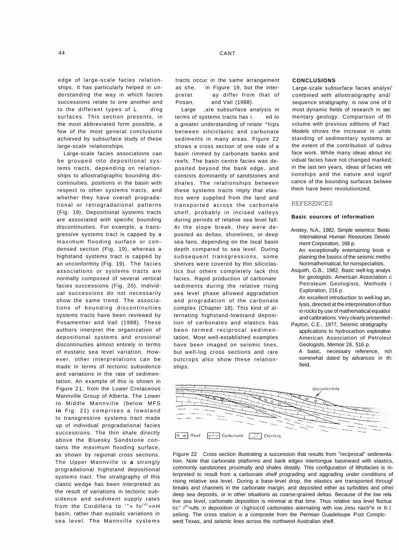
Large ,a le subsurface analysis interms of systems tracts has i. ed toa greater understanding of relate ^hipsbetween si l ic ic last ic and carbonatesediments in many areas. Figure 22shows a cross section of one side of a basin rimmed by carbonate banks andreefs. The basin centre facies was de-posi ted beyond the bank edge, andconsists dominantly of sandstones andsha les . The re la t ionsh ips betweenthese systems tracts imply that elas-tics were supplied from the land andt r a n s p o r t e d ac ross the ca rbona teshe l f , p r o b a b l y in i nc i sed va l leysduring periods of relative sea level fall.A t the s lope break, they were de -posited as deltas, shorelines, or deepsea fans, depending on the local basindepth compared to sea level. Durings u b s e q u e n t t r ansg ress ions , someshelves were covered by thin siliciclas-t ics but others complete ly lack thisfacies. Rapid production of carbonatesediments dur ing the relative risingsea level phase al lowed aggradationand p rograda t ion of the carbonatecomplex (Chapter 18). This kind of al-ternating highstand-lowstand deposi-t ion of carbonates and elastics hasbeen t e r m e d rec ip roca l s e d i m e n -tation. Most well-established exampleshave been imaged on seismic lines,but wel l- log cross sections and rareoutcrops also show these re la t ion-ships.
CONCLUSIONSLarge-scale subsurface facies analysi'combined with allostratigraphy and/sequence stratigraphy, is now one of tlmost dynamic fields of research in secmentary geology. Comparison of thvolume with previous editions of Fact Models shows the increase in undestanding of sedimentary systems arthe extent of the contribution of subsuface work. While many ideas about incvidual facies have not changed marked;in the last ten years, ideas of facies relrt ionships and the nature and signifcance of the bounding surfaces betweethem have been revolutionized.
REFERENCES
Basic sources of information
Anstey, N.A., 1982, Simple seismics: BostoInternational Human Resources Develoment Corporation, 168 p.An exceptionally entertaining book e plaining the basics of the seismic metho Nonmathematical, for nonspecialists.
Asquith, G.B., 1982, Basic well-log analysfor geologists: American Association c Petroleum Geologists, Methods i Exploration, 216 p.An excellent introduction to well-log an, lysis, directed at the interpretation of tlun in rocks by use of mathematical equatioi and calibrations. Very clearly presented -
Payton, C.E., 1977, Seismic stratigraphyapplications to hydrocarbon explorativeAmerican Association of PetroleuiGeologists, Memoir 26, 516 p.A basic, necessary reference, no\ somewhat dated by advances in th: field.
Figure 22 Cross section illustrating a succession that results from "reciprocal" sedimenta-tion. Note that carbonate platforms and bank edges intertongue basinward with elastics,commonly sandstones proximally and shales distally. This configuration of lithofacies is in-terpreted to result from a carbonate shelf prograding and aggrading under conditions ofrising relative sea level. During a base-level drop, the elastics are transported througfbreaks and channels in the carbonate margin, and deposited either as turbidites and otheideep sea deposits, or in other situations as coarse-grained deltas. Because of the low relative sea level, carbonate deposition is minimal at that time. Thus relative sea level fluctuatic" ro<=u!ts ;n deposition o! i lighsicrd carbonates aiiernating with iow.,innu riacti^e m II-.Iseliing. The cross station is a composite from the Permian Guadeloupe P.cct Complc-west Texas, and seismic lines across the northwest Australian shelf.

Van Wagoner, J.C., Mitchum, R.M. Jr.,Posamentier, H.W. and Vail, P.R., 1987,Key definitions of sequence stratig-raphy, in Bally, A.W., ed., Atlas ofseismic stratigraphy. American Asso-ciation of Petroleum Geologists, Studiesin Geology 27, p. 11-14.Many basic definitions presented graph-ically in a large format. All the genetic associations of sequence stratigraphy are shown, with the assumption that eu-static sea level variation is the control-ling parameter of stratigraphic units.
Van Wagoner, J.C., Mitchum, R.M.,Campion, K.M. and Rahmanian, V.D.,1990, Siliciclastic sequence stratigraphyin well logs, cores and outcrops: con-cepts for high-resolution correlation oftime and facies: American Associationof Petroleum Geologists, Methods inExploration Series no. 7, 55 p.This is the latest comprehensive discus-sion of sequence stratigraphy, with many subsurface examples.
Wilgus, C.K., Hastings, B.S., Posamentier,H.W., RQSS, C.A. and Kendall,C.G.St .C, eds., 1988, Sea levelchanges: an intergrated approach:Society of Economic Paleontologistsand Mineralogists, Special Publication42, 407 p.Collection of papers emphasizing con-ceptual basis of sequence stratigraphy plus numerous case studies of sea level change from the geological record.
Other references
Allen, D.R., 1975, Identification of sedi-ments — their depositional environmentand degree of compaction — from welllogs, in Chilingarian, G.V. and Wolf,K.H., eds., Compaction of coarse-grained sediments I: New York,Elsevier, p. 349-402.
Bubb, J.N. and Hatlelid, W.G., 1977,Seismic stratigraphy and globalchanges of sea level, Part 10: Seismicrecognition of carbonate buildups, inPayton, C.E., ed., Seismic stratigraphy— applications to hydrocarbon explo-ration: American Association of Petro-leum Geologists, Memoir 26, p. 185-204.
Flach, P.D., 1984. Oil sands geology — Athabasca deposit north: AlbertaResearch Council, Bulletin 46, 31 p.
3. SUBSURFACE FACIES ANALYSIS
Griff iths, C M . and Bakke, S., 1990,Interwell matching using a combinationof petrophysically derived numericallithologies and gene-typing techniques,in Hurst, A., Lovell, M.A., and Morton,A.C., eds., Geological applications ofwireline logs: Geological Society ofLondon, Special Publication 48, p. 133-151.An example of one numerical technique for log correlation, not as yet widely used by geologists.
Hopkins, J.C., Lawton, D.C. and Gunn,J.D., 1987, Geologic and seismic evalu-ation of a Lower Mannville valleysystem; Aidesson prospect, RollingHills, southwestern Alberta: Bulletin ofCanadian Petroleum Geology, v. 35,p. 296-315.
Hurst, A., Lovell, M.A. and Morton, A.C.,1990, Geological applications of wirelinelogs: Geological Society of London,Special Publication 48, 357 p.
Krumbein, W.C. and Sloss, L.L., 1963,Stratigraphy and sedimentation: SanFrancisco, W.H.Freeman and Co., 660 p.
Miall, A.D., 1984, Principles of BasinAnalysis: New York, Springer Verlag,490 p.
Nurkowski, J.R. and Rahmani, R.A., 1984,An Upper Cretaceous fluvio-lacustrinecoal-bearing sequence, Red Deer area,Alberta, Canada, in Rahmani, R.A. andFlores, R.M., eds., Sedimentology ofcoal and coal-bearing sequences:International Association of Sedi-mentologists, Special Publication 7,p. 163-176.
Example of the use of bentonitic marker beds and slices in subdividing an uncor-rectable unit.
Posamentier, H.W. and Vail, P.R., 1988,Eustatic controls on clastic deposition II— Sequence and systems tract models,in Wilgus, C.K., et al., eds., Sea-levelchanges — an integrated approach:Society of Economic Paleontologistsand Mineralogists, Special Publication42, p. 125-154.A complete exposition of the relation-ships between facies, facies succes-sions, depositional systems tracts, transgressive surfaces, and erosional surfaces. The interpretation of eustasy as the only controlling parameter may be overstated, but the basic relation-ships discussed in this paper are of prime importance in large-scale strati-graphic and sedimentological analysis.
45
Roksandic, M.M., 1978, Seismic faciesanalysis concepts: GeophysicalProspecting, v. 26, p. 383-398.
Sangree, J.B. and Widmier, J.M., 1977,Seismic stratigraphy and globalchanges of sea level, Part 9: Seismic in-terpretation of clastic depositionalfacies, in Payton, C.E., ed., Seismicstratigraphy — applications to hydro-carbon exploration: American Asso-ciation of Petroleum Geologists, Memoir26, p. 165-184.
Sarg, J.F., 1988, Carbonate sequencestratigraphy, in Wilgus, C.K., et al., eds.,Sea-level changes — an integrated ap-proach: Society of Economic Paleon-tologists and Mineralogists, SpecialPublication 42, p. 155-181.
Selley, R.C., 1978, Concepts and methodsof subsurface facies analysis: AmericanAssociation of Petroleum Geologists,Continuing Education Course NotesSeries 9, 82 p.
Vail, P.R., Todd, R.G. and Sangree, J.B.,1977, Seismic stratigraphy and globalchanges of sea level, Part 5: chrono-stratigraphic significance of seismic re-flections, in Payton. C P <-'< 0 r > l r ™ ! "stratigraphy, — applicantcarbon exploration: Amencoi.ciation of Petroleum Geologists, Memoii26, p. 99-133.


![[PPT]Facies and Facies Models - UCSC Directory of individual …mclapham/eart120/slides/Facies... · Web viewWhat is a facies? A sedimentary unit with consistent characteristics (lithology,](https://img.pdfslide.net/doc/110x75/5aef4a8a7f8b9a8c308bc665/pptfacies-and-facies-models-ucsc-directory-of-individual-mclaphameart120slidesfaciesweb.jpg)