Embed Size (px)
Citation preview

30-0352TRU-BOOSTX
Boost Controller Gauge
AEM Performance Electronics, 2205 126th Street Unit A, Hawthorne, CA 90250 - Phone: (310) 484-2322http://www.aemelectronics.com
STOP! - READ THIS BEFORE INSTALL OR USE!
WARNING:
THIS INSTALLATION MAY REQUIRE WELDING OR INTEGRATION INTO A VEHICLE'S ELECTRICAL SYSTEM. DAMAGE TO
SENSITIVE ELECTRONICS, FIRE, OR EXPLOSION MAY OCCUR IF PROPER PRECAUTION IS NOT TAKEN. IF THERE IS ANY
DOUBT, DO NOT ATTEMPT THE INSTALLATION AND CONSULT A PROFESSIONAL. NOTE: IT IS THE RESPONSIBILITY OF
THE ENGINE TUNER TO ULTIMATELY CONFIRM THE CALIBRATION USE FOR ANY PARTICULAR ENGINE IS SAFE FOR ITS
INTENDED USE. AEM HOLDS NO RESPONSIBILITY FOR ANY ENGINE DAMAGE THAT RESULTS FROM THE MISUSE OF
THIS PRODUCT.
THIS PRODUCT HAS LEGAL RESTRICTIONS. READ THIS BEFORE INSTALL OR USE!
THIS PRODUCT MAY BE USED SOLELY ON VEHICLES USED IN SANCTIONED COMPETITION WHICH MAY NEVER BE USED UPON A PUBLIC ROAD
OR HIGHWAY, UNLESS PERMITTED BY SPECIFIC REGULATORY EXEMPTION. (VISIT THE “EMISSIONS” PAGE AT
HTTP://WWW.SEMASAN.COM/EMISSIONS FOR STATE BY STATE DETAILS.) IT IS THE RESPONSIBILITY OF THE INSTALLER AND/OR USER OF
THIS PRODUCT TO ENSURE THAT IT IS USED IN COMPLIANCE WITH ALL APPLICABLE LAWS AND REGULATIONS. IF THIS PRODUCT WAS
PURCHASED IN ERROR, DO NOT INSTALL AND/OR USE IT. THE PURCHASER MUST ARRANGE TO RETURN THE PRODUCT FOR A FULL REFUND.
THIS POLICY ONLY APPLIES TO INSTALLERS AND/OR USERS WHO ARE LOCATED IN THE UNITED STATES; HOWEVER CUSTOMERS WHO
RESIDE IN OTHER COUNTRIES SHOULD ACT IN ACCORDANCE WITH THEIR LOCAL LAWS AND REGULATIONS.
InstructionManual
The AEM Tru-BoostX Controller Gauge is a stand-alone boost controller that features a four-digit central readout with 24sweeping LED's, providing immediate reference to the boost reading in real-time. An AEMnet (CAN bus) output is includedand can be used with AEM devices such as the Dash Displays.
Features
· 2-1/16" / 52mm outer diameter mounting· On-board pressure sensor, measures up to 80 PSIg· Locking connector· Supports vehicle / system voltages up to 16V· Auto-dimming display· Displays both vacuum and boost· Three programmable boost settings (high boost, low
boost, and scramble boost)· Three operating modes (A, B, and OFF)· Two over-boost alarm feature· One negative-active lowside output for external alarm
lamp· One negative-triggered input for scramble boost
activation· One AEMnet (CAN bus) output· Peak boost recall feature· Programmable display units (PSIg, BAR, and KPg)· Programmable LED scale· Programmable waste-gate opening hold-off pressure· Black bezel / "Boost" faceplate supplied; Silver / white
available as optional purchase
KIT CONTENTS
PN Description
10-4352 INST, X-SERIES TRU BOOST GAUGE
35-4352 GAUGE ASSY, X-SERIES TRU BOOST
35-4303 INSTALL KIT
35-8618 NUT, KNURLED, M4x0.7 (2)
35-8614 BRACKET, X-SERIES GAUGE
35-3447 HARNESS, TRU BOOST CONTROLLER
35-8617 RUBBER BAND, X-SERIES GAUGE
35-2400 BOOST CONTROL SOLENOID
35-2401 BOOST CONTROL MUFFLER
35-2152 1/8 NPT MALE TO -4 MALE ADAP (2)
35-2153 1/8 NPT MALE TO 3/16 BARB ADAP (2)
8-158 ADAPTER, 1/8" HOSE TO 1/8" NPT
8-161-120 VACUUM HOSE, 7/64" X 120"
*OPTIONAL* ACCESSORIES
PN Description
30-0352-
ACC
BEZEL, X-SERIES GAUGE SILVER
FACEPLATE, X-SERIES TRU BOOST WHITE

2
10/2/2019 - DOCUMENT NUMBER: 10-4352 © 2019 AEM Peformance Electronics
30-0352 Tru-BoostX Gauge User Manual
Gauge Installation
Installation using supplied bracket Installation w ithout bracket, using rubber band
A 2-1/16" (52mm) hole is required to mount the X-Series gauge. A bracket and thumbscrews are provided to facilitateinstallation into a panel or gauge pod. In some cases, the gauge cup may be pushed into a mounting hole causing aninterference fit strong enough to retain the gauge; the supplied rubber band may be fit to the gauge to create a tighter fit inmounting holes slightly larger than 52mm. It is, however, recommended that gauges be mounted securely using thesupplied bracket to ensure they never become loose and cause a hazard during vehicle operation. The gauge panel aboveis for illustrative purposes only, it is not supplied.
Note: The gauge is not water-proof and should not be installed in a location with exposure to water or snow. Damagecaused by water ingress will not be covered under warranty.
Refer to the Wiring Installation Diagram for details on how to connect the gauge harness to the vehicle. Then, connect thecable to the gauge. The connector will only fit one way. In addition, the boost hose protruding from the back of the gaugeis connected to the onboard pressure sensor. The manifold boost hose must be connected to the manifold for thecontroller to work properly. Connect the manifold boost hose to manifold using the supplied tubing and 1/8" NPT barb oran existing manifold pressure port.
Note: Do not pull on the boost hose as physical damage may occur.

3
10/2/2019 - DOCUMENT NUMBER: 10-4352 © 2019 AEM Peformance Electronics
30-0352 Tru-BoostX Gauge User Manual
Wiring Installation Diagram

4
10/2/2019 - DOCUMENT NUMBER: 10-4352 © 2019 AEM Peformance Electronics
30-0352 Tru-BoostX Gauge User Manual
Gauge ConnectionsThe X-Series Tru-BoostX Controller Gauge is supplied with a Power/IO harness; the harness is connected to the gauge asshown below. The Power/IO harness will require further integration into the vehicle. The minimum Power/IO connectionsrequired to operate the gauge are switched 12V (5A fuse) and ground. The boost solenoid and hose need to be connectedas well. Please reference the diagrams and information on the provided for further detail.
Connector A - Power / IO
Pin Color Description
1 RED Switched 12V Power (5A Fuse)
2 BLACK Power Ground
3 GREEN/BLACK AEMnet- / CANL (Optional)
4 WHITE/BLACK AEMnet+ / CANH (Optional)
5 ORANGE Scramble Boost (Optional)
6 - 8 - Not Used
9 BLACK Boost Solenoid OutputNegative-
10 GRAY Alarm Lowside OutputNegative- (Optional)
Important Notes on Wiring· Route harnesses carefully to avoid chafing or undue strain.· Apply strain reliefs and wire coverings as necessary (not
included).· Secure wiring to vehicle with wire ties (not included)· Use a 5A inline fuse on the switched 12V power supply
line (Pin 1 - Power/IO).· Match the existing wire gauge when extending wires.· Ensure all connections are secure and insulated from
shorts to adjacent wires and the vehicle structure. Utilizeproper crimping and solder/heat-shrink techniques.
· Replacement pins are JST P/N SPUD-001T-P0.5 terminalsfor 22-26 AWG wire.

5
10/2/2019 - DOCUMENT NUMBER: 10-4352 © 2019 AEM Peformance Electronics
30-0352 Tru-BoostX Gauge User Manual
Boost Solenoid InstallationWhen energized, ports 1 & 2 are connected, when de-energized, ports 2 & 3 are connected. The port numbers are clearlynoted on the solenoid body. See the diagrams below for plumbing instructions.

6
10/2/2019 - DOCUMENT NUMBER: 10-4352 © 2019 AEM Peformance Electronics
30-0352 Tru-BoostX Gauge User Manual
OperationThe inner numeric LEDs and outer ring LEDs display the currently measured manifold pressure; the outer LEDs will flashwhen the sensor reading exceeds the (configurable) warn/alarm threshold value. Button A and button B are located on theface of the gauge and are used to configure the boost controller gauge.
Select operating mode (A, B, OFF)§ The gauge should be in its run mode, showing the current
sensor reading§ Depress and hold the A button for three seconds until the
next mode appears§ Repeat until the desired mode is selected§ Select mode A to use the boost setting A§ Select mode B to use the boost setting B§ Select mode OFF to disable the boost solenoid§ The gauge will return to run mode shortly after the last
button press§ Press the A button and the current mode will be displayed
Display peak value§ The gauge should be in its run mode, showing the current
sensor reading§ Press the B button; the peak (highest) sensor reading will
be displayed after "HI" is displayed§ The peak value will be reset to zero after every power
cycles§ The gauge will return to run mode shortly after the last
button press
Clear stored peak value§ The gauge should be in its run mode, showing the current
sensor reading§ Depress and hold the B button for three seconds until
"CLr" appears to clear the peak valueWill be displayed to confirm the peak valuehas been reset
§ The gauge will return to run mode shortly after the lastbutton press
Enter quick setup menu§ The gauge should be in its run mode, showing the
current sensor reading§ Depress and hold the A and B button together for
three seconds until "PRG" appears§ Press the A button; boost setting A and the current
manifold pressure will be displayed alternatively. Oncethe manifold pressure is over one PSI, only the currentmanifold pressure is displayed.
§ Set the output duty cycle (10%-90%) for mode A.§ Use the A button to decrease the value and use the B
button to increase the value§ Press the A and B button together for one second to
move on to boost setting B. Boost setting B and thecurrent manifold pressure will be displayedalternatively. Once the manifold pressure is over onePSI, only the current manifold pressure is displayed.
§ Set the output duty cycle (10%-90%) for mode B.§ Press the A and B button together for one second to
return to run mode
Enter full setup menu§ The gauge should be in its run mode, showing the
current sensor reading§ Depress and hold the A and B button together for
three seconds until "PRG" appears§ Depress and hold the A and B button together once
more for three seconds until "UNIT" appears§ Use the A button to decrease the value and use the B
button to increase the value of the desired settings§ Press the A and B button together for one second to
move on to the next setting§ To exit, continue the setup until the run mode is
reached
Menu Options:Change display units
§ The gauge should be in setup mode alternatingbetween "Unit" and the current unit setting
§ Select from PSIg ("PSI"), Bar ("bAr"), and Kpg("PAS").
Change scramble boost duty cycle§ The gauge should be in setup mode alternating
between "SCb" and the current duty cycle setting§ Set the output duty cycle (10%-90%) for the scramble
boost feature. The Tru-BoostX controller will output theselected duty cycle when the scramble boost input isgrounded.
7
10/2/2019 - DOCUMENT NUMBER: 10-4352 © 2019 AEM Peformance Electronics
30-0352 Tru-BoostX Gauge User Manual
Change scramble time§ The gauge should be in setup mode alternating
between "SCt" and the current time setting§ Select the duration of time (0-25.5 seconds) the Tru-
BoostX controller will output the scramble boostduty cycle when the scramble boost input isgrounded.
Change alarm pressure§ The gauge should be in setup mode alternating
between "ALA" and the current pressure setting§ Set the boost pressure at which the alarm will
activate. When the alarm is activated, the LEDs willflash and the warning light output (gray wire) ispulled to ground.
Change wastegate crack pressure§ The gauge should be in setup mode alternating
between "oPP" and the current pressure setting§ Set the boost pressure at which the wastegate
starts to open. The Tru-BoostX controller will keepthe boost solenoid open from one PSI until the boostexceeds the selected value. This value can beadjusted to reduce lead in boost spikes or reducespool up time. It is recommended that this setting isset 2-3 PSI below the actual crack pressure.
Change display full scale§ The gauge should be in setup mode alternating
between "FULL" and the current scale setting§ Set the full-scale value of the sweeping LED lights.
The LED lights start at 0 PSIg and stop at the full-scale value, increasing in twenty-four equalincrements.
Change boost setting A§ The gauge should be in setup mode alternating
between boost setting A and the current manifoldpressure. Once the manifold pressure is over onePSI, only the manifold pressure is displayed.
§ Set the output duty cycle (10%-90%) for mode A.When in mode A, this is the duty cycle the Tru-BoostX controller will output.
Change boost setting B§ The gauge should be in setup mode alternating
between boost setting B and the current manifoldpressure. Once the manifold pressure is over onePSI, only the manifold pressure is displayed.
§ Set the output duty cycle (10%-90%) for mode B.When in mode B, this is the duty cycle the Tru-BoostX controller will output.
§ Press the A and B button together for one second toreturn to the run mode.
Setup Menu Tree
8
10/2/2019 - DOCUMENT NUMBER: 10-4352 © 2019 AEM Peformance Electronics
30-0352 Tru-BoostX Gauge User Manual
How It WorksTurbo Boost ControlIn a turbo-charged application, the wastegate varies the amount of exhaust gases to the exhaust turbine. Thus, thewastegate essentially regulates the amount of boost produced by the turbocharger. Typically, the wastegate has aninternal spring that is preset to open at a certain pressure commonly known as the Wastegate Crack Pressure or SpringPressure. Boost pressure is supplied to the wastegate as a reference. When the boost pressure exceeds the wastegatecrack pressure, the wastegate vents excess exhaust gases, effectively reducing the boost output. With no pressure to thewastegate, the wastegate is shut and the turbo continues to build boost. By adding a boost solenoid, the wastegateboost pressure reference can be manipulated electronically to change the turbocharger boost output. The boost solenoidis configured in a way that if the boost control is disabled, the wastegate operates at the default spring pressure.
Pulse Width Modulation (PWM)The technique used to control the boost solenoid is Pulse Width Modulation commonly known as PWM. The Tru-BoostXcontroller is configured to pulse the boost solenoid at a frequency of 30 Hertz. The solenoid is driven high and low rapidlyand the duty cycle is used to specify the duration of time the boost solenoid is held open. Using this approach, thesolenoid emits a buzzing sound.
Duty CycleEach time period or cycle has two component, on-time and off-time. Duty cycle is the percentage of on-time. Adjustingthe duty cycle allows the solenoid to bleed more or less air from the wastegate boost pressure reference port. Remember,venting all the air from the wastegate means it will allow the turbo to build maximum boost.
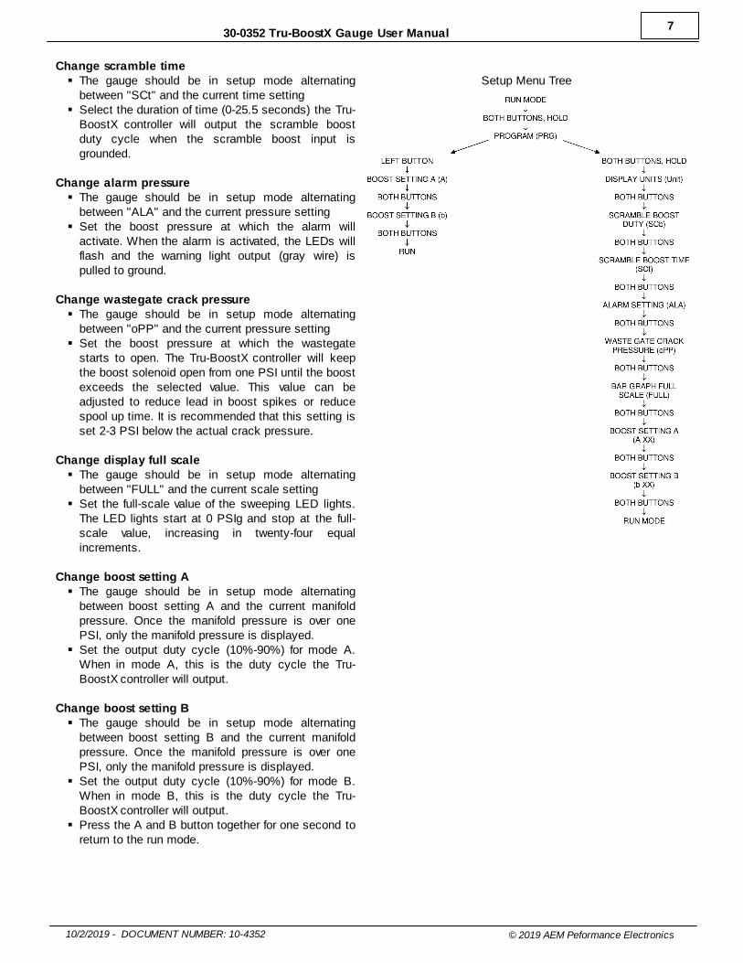
More Duty = More BoostTo understand how the solenoid becomes a variable air flow restricting valve to meet a specific wastegate position, note
the following duty cycle signal examples.
The oscilloscope trace above shows a 30Hz, 50% duty
cycle signal coming from the controller. The solenoid will
be ON when the signal is low and OFF when the signal is
high.
The oscilloscope trace above shows a 30Hz, 20% duty
cycle signal. The solenoid will be ON when the signal is
low (20% of the time) and OFF when the signal is high
(80% of the time).
Correlating Duty Cycle and Boost PressureThe boost controller has no idea how much duty is required to achieve a specific amount of boost. Since, each turbo-charged application will be different, the boost controller has to be tuned so that the boost controller will know how muchduty cycle will create the target boost.

9
10/2/2019 - DOCUMENT NUMBER: 10-4352 © 2019 AEM Peformance Electronics
30-0352 Tru-BoostX Gauge User Manual
LimitationsThe boost solenoid is not usable at any duty less than 10%. Thus, at 10% the boost solenoid is considered off. Likewise,maximum on duty is capped at 90%. In addition, the minimum and maximum boost created is also limited by either thewastegate or the turbocharger itself. Upgrading the wastegate and/or turbocharger may be required to achieve the desiredboost level the current setup cannot provide.
Using the Tru-BoostX controller gaugeThe Tru-BoostX controller must be tuned for the specific application. Setup the gauge through the setup menu. Tune theboost controller by adjusting boost setting A and B, as well as the scramble boost setting (if used) until the desiredpressure is achieved under load. The quick setup menu is perfect for quickly adjusting the duty cycle. The WastegateCrack Pressure (oPP) setting may be adjusted to reduce lead in boost spikes or reduce spool up time. It is recommendedthat this setting is set 2-3 PSI below the actual crack pressure.
Once tuned, choose a running mode (A, B, or OFF). In all modes, the sweeping LEDs will not illuminate when manifoldpressure is less than 0 PSIg. In mode A, the gauge will output the duty cycle selected for boost setting A. The gauge willoutput the duty cycle selected for boost setting B when in mode B. In the "OFF" mode, the solenoid output is turned off.Press and hold the left button for three seconds to change run modes. The order of run modes is shown in the menu treebelow. The gauge also remembers the peak boost level achieved. Press the B button to display the peak boost. Press andhold the B button for three seconds to clear the peak boost value.
Button A and Button B
Scramble BoostScramble boost is a feature that allows the driver to momentarily change the duty cycle output of the Tru-BoostXcontroller. The output duty cycle for the scramble boost is set in the scramble boost (SCb) option. The scramble boostduration is set by the scramble boost time (SCt) option. Scramble boost is activated by grounding the orange scrambleboost input wire.
AlarmAll 24 outer LEDs will flash if manifold pressure exceeds the alarm value (ALA) for more than 1 second. The low sidedriver output will also switch to ground. The LEDs will continue to flash and the output will stay grounded until eitherbutton is pushed or the gauge is turned off.
Over-BoostThe boost solenoid will shut off, all 24 outer LEDs will flash and the center digits will display "Ob" if manifold pressureexceeds the alarm value by 10% for more than 1 second or if manifold pressure exceeds the alarm level by 20% for morethan 200 milliseconds. The solenoid will remain off and the LEDs will continue to flash until either button is pushed or thegauge is turned off.
Error DetectionErS- If the boost solenoid is shorted or disconnected, the LEDs will flash and the center digits will display “ErS”. The errorcode will not activate when the Tru-BoostX is in the off mode. Note: The solenoid always has a small PWM signal to allowfor fault detection.

10
10/2/2019 - DOCUMENT NUMBER: 10-4352 © 2019 AEM Peformance Electronics
30-0352 Tru-BoostX Gauge User Manual
Faceplate / Bezel InstallationThe gauge kit is supplied assembled with a black faceplate and black bezel. An accessory kit is available (for purchasethrough AEM dealers) which includes an optional silver bezel and white faceplate. Please reference the OptionalAccessories section earlier in the document for the appropriate part numbers. Contact your dealer or visitwww.aemelectronics.com for more information.
The faceplate is not reversible. Dis-assembly is required to change the faceplate or change the bezel of the gauge. Thefollowing diagram will provide familiarization with the major components of the gauge prior to beginning the procedure.
Item Qty Description
1 1 Lens
2 1 Bezel
3 1 Faceplate
4 1 Diffuser
5 1 Light Guide
6 2 Button
7 1 Cup w/ Mounting Stud (M4 x 0.7)
8 3 Assembly Screw
9 1 Mounting Bracket
10 2 Brass Thumb Screw (M4 x 0.7)
11 1 Printed Circuit Board (PCB)
12 1 Manifold Boost Hose

11
10/2/2019 - DOCUMENT NUMBER: 10-4352 © 2019 AEM Peformance Electronics
30-0352 Tru-BoostX Gauge User Manual
Gauge Disassembly
STEP 1 - Remove the three assembly screws (8) using a #1 Phillips
head screwdriver. Separate the bezel (2) and cup (7) from the rest of the
assembly. If you have purchased the optional accessory kit, the silver
bezel may be replaced for the existing bezel at this time.
STEP 2 - Separate the PCB (11) and cup (7) from the remaining
components. *Under no circumstance attempt to detach the
manifold boost hose (12) from the PCB!
STEP 3 - Slide the light guide (5) upward to remove it, the buttons may
fall out at this time - take care not to lose them.
STEP 4 - As you separate the remaining components, diffuser (4),
faceplate (3), lens (1), note the order in which they were assembled.
The faceplate (3) may now be replaced for a different color as included in
the optional accessory kit.
12
10/2/2019 - DOCUMENT NUMBER: 10-4352 © 2019 AEM Peformance Electronics
30-0352 Tru-BoostX Gauge User Manual
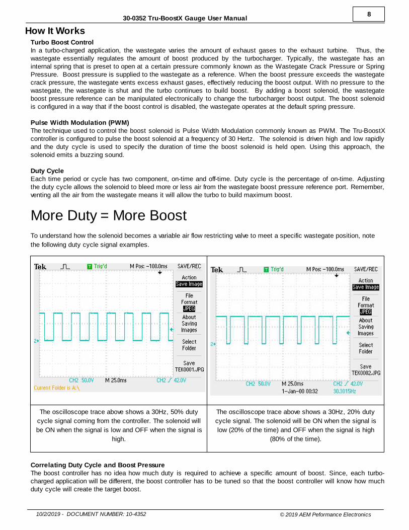
Gauge Assembly
STEP 1 - Place the light guide (5) on a flat surface (black side up) and
slide the buttons (6) into the slots.
STEP 2 - Stack the diffuser (4), faceplate (3), and lens (1) in order, over
the buttons, and on to the light guide.
STEP 3 - Reassemble the PCB and display stack with the bezel, making
sure screw holes are aligned through the entire assembly.
STEP 4 - Re-assemble and tighten screws to 2 in-lb (previously
assembled bezel) or 3 in-lb (new bezel). Do not over-tighten!

13
10/2/2019 - DOCUMENT NUMBER: 10-4352 © 2019 AEM Peformance Electronics
30-0352 Tru-BoostX Gauge User Manual
AEMnet (CAN bus) OutputWHITE WIRE WITH BLACK STRIPE = AEMnet+ / CANHGREEN WIRE WITH BLACK STRIPE = AEMnet- / CANL
The AEMnet output is suitable for output to AEM devices such as the Dash Displays. The following CAN configurationand message definition information is provided below to facilitate interface with third-party devices.
Bus TerminationAll AEMnet/CAN networks must be terminated to have anequivalent of approximately 60 Ohms of resistance. Generally, this means a 120 Ohm resistor connected inparallel to AEMnet+/AEMnet- (or CANH/CANL) at bothphysical ends of the bus run. The X-Series device does nothave any internal termination and is intended to beconnected to a pre-existing, properly terminated network. Please refer to the Bosch CAN2.0B specification for furtherdetail.
bit rate 500 Kb/Sec
format 29 bit ID
transmit rate 20 Hz
terminating resistor none
endianness big / Motorola
DLC 8
Message ID 0x000A0310
Byte Bit Bitmask Label Data Type Scaling Offset Range
0-1 - - Boost Press 16 bitunsigned
0.01 PSIg / bit 0.0 0 to 655.35 PSIg
2-3 - - Over-boost AlarmThreshold
16 bitunsigned
0.01 PSIg / bit 0.0 0 to 655.35 PSIg
4-5 - - Boost Max 16 bitunsigned
0.01 PSIg / bit 0.0 0 to 655.35 PSIg
6-7 - - Wastegate Crack Press 16 bitunsigned
0.01 PSIg / bit 0.0 0 to 655.35 PSIg
Message ID 0x000A0311
Byte Bit Bitmask Label Data Type Scaling Offset Range
0 - - Boost Control Output 8 bitunsigned
1 % / bit 0 0 to 255 %
1 - - Boost Control ScrambleDuty
8 bitunsigned
1 % / bit 0 0 to 255 %
2 - - Boost Control Target ADuty
8 bitunsigned
1 % / bit 0 0 to 255 %
3 - - Boost Control Target BDuty
8 bitunsigned
1 % / bit 0 0 to 255 %
4 - - Boost Scramble Timeout 8 bitunsigned
0.1 s / bit 0 0 to 25.5 s
5 4-7(MSB)
16 Reserved - - - -
3 8 Boost Solenoid Status Boolean 0 = "OK", 1 ="Error"
0 0/1
2 4 Over-boost Status Boolean 0 = "OK" , 1 ="Over-boost"
0 0/1

14
10/2/2019 - DOCUMENT NUMBER: 10-4352 © 2019 AEM Peformance Electronics
30-0352 Tru-BoostX Gauge User Manual
1 2 Over-boost ShutdownStatus
Boolean 0 = "OK", 1 ="Shutdown"
0 0/1
0 (LSB) 0 Scramble Boost InputState
Boolean 0 = "Off", 1 = "On" 0 0/1
6-7 - - Reserved - - - -
FAQ / TroubleshootingWhat are the minimum wiring connections needed to use the gauge?Switched/fused 12V (RED) and power ground (BLACK) must be supplied to the 10 pin connector. The boost solenoidneeds to be connected to the 10 pin connector as well. See the Wiring Installation Diagram for more details. Any unusedwires may be secured and fastened away for future use.
The LEDs flashes and the center digits display "ErS".The boost controller gauge detected a short or disconnect in the boost solenoid circuit. Check the wiring and correct anyissues.
Why is my gauge not showing boost or vacuum?The gauge is not connected to a source that sees manifold pressure.
What is a good source for manifold pressure?The best source would be a port on the intake manifold. Alternatively, the manifold boost hose can be tee off of theexisting vacuum hoses. Ensure there are no flow control devices that can interfere with the pressure reference, e.g. checkvalves, solenoids.
My gauge is displaying boost pressure but the solenoid is not activating.Ensure that the boost controller gauge is in either mode A or mode B. Boost solenoid control is disabled in mode Off.
How do I know what mode the gauge is in?The gauge will display the mode when it is turned on. Press the A button to display the mode during operation.
Why is the boost is not increasing?Make sure the gauge is in mode A or B and that the Wastegate Crack Pressure "oPP" and the boost settings areconfigured. Check the solenoid plumbing.
What does spring setting mean? What should I set this to?Spring setting or Wastegate Crack Pressure "oPP" is the boost pressure at which the Wastegate starts to open. Thisvalue can be adjusted to reduce lead in boost spikes or reduce spool up time. It is recommended that this setting is set 2-3 PSI below the actual crack pressure.
What do I have to set this gauge to in order to make x boost?Every setup will act differently due to differences in engine size, turbo size, and other set up aspects. Hence, there is nooption to just input a boost target. Try the following. Set the Wastegate Crack Pressure "oPP". As a safety net, set thealarm "ALA" to the target boost. Increase either boost setting A or B under load until the target boost is achieved. Set thegauge to the corresponding mode and confirm that the boost target is being met under driving conditions.
Can I extend the wires in my power harness?Yes, but match the existing wire gauge use of proper crimping/soldering techniques is required.
Can I extend the vacuum line?It is not recommended that the vacuum line is extended beyond the length of the hose already supplied, 10FT. The shorterthe hose between the gauge and the manifold, the better.

15
10/2/2019 - DOCUMENT NUMBER: 10-4352 © 2019 AEM Peformance Electronics
30-0352 Tru-BoostX Gauge User Manual
Specifications
Dimensions diameter (bezel) 2.40 / 61 in / mm
diameter (cup) 2-1/16 / 52 in / mm
depth (incl. bezel) 0.825 / 21 in / mm
depth (cup only) 0.200 / 5 in / mm
Supply Voltage min 7 VDC
max 18 VDC
Supply Current (13.8V) nominal 1.5 A
peak 3 A
Lowside Current max 1.5 AOperating Temperature min -4 / -20 degF / degC
max (16V Supply) 185 / 85 degF / degC
Operating Pressure vacuum -29 inHg
max boost 80 PSI
CAN 2.0B Output bit rate 500 Kb/Sec
format 29 bit ID
transmit rate 20 Hz
terminating resistor none
endianness big / Motorola
Message/Arbitration ID 0x000A0310-0x000A0311
DLC 8
12 Month Limited WarrantyAEM Performance Electronics w arrants to the consumer that all AEM ELECTRONICS products w ill be free from defects in material and
w orkmanship for a period of tw elve months from date of the original purchase. Products that fail w ithin this 12-month w arranty period w ill be
repaired or replaced w hen determined by AEM that the product failed due to defects in material or w orkmanship. This w arranty is limited to the
repair or replacement, at AEM’s discretion, of the AEM Electronics part. In no event shall this w arranty exceed the original purchase price of the
AEM ELECTRONICS part nor shall AEM ELECTRONICS be responsible for special, incidental or consequential damages or cost incurred due to the
failure of this product.
Warranty claims to AEM ELECTRONICS must be transportation prepaid and accompanied by dated proof of purchase. This w arranty applies only
to the original purchaser of product and is non-transferable. All implied w arranties shall be limited in duration to the said 12-month w arranty period.
Improper use or installation, accident, abuse, unauthorized repairs or alterations voids this w arranty.
AEM ELECTRONICS disclaims any liability for consequential damages due to breach of any w ritten or implied w arranty on all products
manufactured by AEM ELECTRONICS.
Warranty returns w ill only be accepted by AEM ELECTRONICS w hen accompanied by a valid Return Merchandise Authorization (RMA) number.
Product must be received by AEM ELECTRONICS w ithin 30 days of the date the RMA is issued.
Please note that before AEM ELECTRONICS can issue an RMA for any electronic product, it is f irst necessary for the installer or end user to
contact the tech line at 1-800-423-0046 to discuss the problem. Most issues can be resolved over the phone. Under no circumstances should a
system be returned, or an RMA requested before the above process transpires. AEM ELECTRONICS w ill not be responsible for products that are
installed incorrectly, installed in a non-approved application, misused, or tampered w ith.
Fuel Pumps installed w ith incorrect polarity (+&- w ires crossed) w ill not be w arranted. Proper fuel f iltration before and after the fuel pump are
essential to fuel pump life. Any pump returned w ith contamination w ill not be w arranted.
Any AEM ELECTRONICS product, excluding discontinued products, can be returned for repair if it is out of the w arranty period. There is a minimum
charge for inspection and diagnosis of AEM ELECTRONICS parts w hich are out of w arranty. Parts used in the repair of AEM ELECTRONICS
electronic components w ill be extra. AEM ELECTRONICS w ill provide an estimate of repairs and must receive w ritten or electronic authorization
before repairs are made to the product.
Need additional help? Contact the AEM Performance Electronics tech department at 1-800-423-0046 or email us at [email protected].