Embed Size (px)
Citation preview

Paper Classification number: T-I
30 Years OfMSR Restoration And Upgrade, An Experience Base For FutureDesigns
Abraham L. YardenThermal Engineering [nternational
California, USA
Clement W. TamThermal Engineering [nternational
California, USA
AkiraOkabeHitachi, Ltd., Power & Industrial
System, Japan
Abstract
Many existing Nuclear power plants world-wide areundergoing a new birth - approaching the end of theirinitial licensing period, their generating capacity is nowbeing uprated through a recognition of the conservatism oftheir initial design; their MSRs upgraded to restoredeteriorated performance, eliminate historically highmaintenance costs and to meet the added needs of thisplant uprating; and re-licensed for continued operation intothe years ahead. An important aspect of this process is therecognition that the moisture separator reheaters (MSRs)can no longer be considered to be mere balance-of-plant(BOP) auxiliaries - their significant impact on MWegeneration, plant operating stability, and reliability hasbecome increasingly appreciated. Over the years in excess90 sets of MSRs have been already redesigned andreconstructed worldwide.
Over the past 30 years, MSRs of every type, and lately MSvessels have been upgraded for a variety of operationalreasons to take full advantage of the advancing technologythat has emerged on many ITonts. While this has permittedthe plant upratings currently in progress and decreased theunacceptably high maintenance costs and MWe lossexperienced, it has also, perhaps more importantly, pointedthe way toward the efficient, reliable MSR designsrequired for the new generation of much larger nuclearpower plants being built and planned for the years ahead.
1 INTRODUCTION
There are a wide variety of specific moisture separatorreheater (MSR) designs and several moisture separator(MS) designs for original equipment, which were createdover the years. For this reason, MSR and MS redesign andreconstruction projects have, of necessity, been unique tothe specific design - there is no standard to the MSR orMS upgrade process. These projects run the gamut ITommere moisture-separation system replacement all the wayto total redesign and replacement of entire MSRs includingthe vessels. To illustrate both the range and specifics ofthese successfully completed projects, several are cited
here. Overall, this will clearly show that the nuclearindustry has in hand the wherewithal to meet thecontinuing needs of today and challenges of the future inproviding the advanced MSR technology that will assurelong-term successful operation of the new, large LWRnuclear power plants to come.
A good example of this is the relatively recent advent ofnuclear power in the Peoples Republic of China which hasgiven stimulus to new MSR original-equipment designs.Although its first indigenous nuclear power plant, a 300MWe PWR at the Qinshan site, was equipped with MSRslargely similar to the licensor's original design, the fournew 700-MWe units now under construction and nearingcompletion employ advanced MSR designs and areexpected to show improvements in performance,reliability, and life over those recently built in east Asiausing standard earlier designs. These new designs atQinshan do not depart from the well-established designprinciples of the past. Rather, they evolve ITom them andimprove them in areas of real impact - size, accessibility,flow streamlining, and resistance to flow-assisted corrosion(FAC).
Broadly speaking, MSR components can be classified asmoisture separators, reheaters, and vessels. Within each ofthese component classifications, there exist a wide varietyof active and passive element considerations - thermal,hydraulic, mechanical, metallurgical, radiological,architectural, and structural for example includingunique installation problems and schedules.
2 MOISTURE SEPARATORS (MS)
The efficiency of originally installed moisture separators(MS) in non-reheat and reheat nuclear steam cycles, hasalways been doubtful. Efficiency levels achieved in oldMS technologies lacked means of quantification, andassumptions made regarding their efficiency were highlyoptimistic. As a result these MSs in reheat cycles havetraditionally been unnecessarily high consumers of inletthrottle and/or extraction steam, if only to evaporatemoisture not mechanically separated. This inefficiency

was ITequently exacerbated by poor HP-turbine exhaustdistribution across the MS elements.
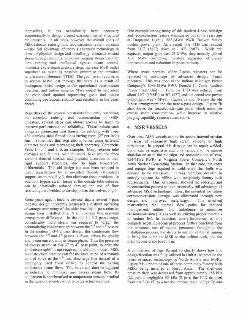
Today's advanced MS design technology includes twobasic parts that address both the former shortcomings perforated plates immediately upstream of the mechanicalmoisture separator chevron vanes now can assure nearlyequal HP-turbine exhaust distribution across the entireopen face of the MS chevron vanes, and modem doublepocket chevron vanes that result in essentially 100-percentMS efficiency. Figure I show the "V" arrangement of theMS elements in a modem MSR configuration. Figure 2 isa photo of the installation of the flow-redistributingperforated plates, just upstream of the double-pocketchevron vanes. Figures 3a and 3b show a MS doublepocket chevron vane arrangement and a photo of a smallsection of it.
While moisture separation section reconstruction, using themodem-technology components has singularly contributedto increases in MWe output of past MSR and MS vesselredesign and reconstruction projects, the MS contributionis usually combined with other factors, such as reheaterrestoration which also constitutes a major contributor.However the specific MS contribution toward these endscan be established in the case of recent projects at two nonreheat nuclear power plants in the central US that usemoisture separators only, and in a recent MS sectionupgrade project at a Carolina Plant MSR.
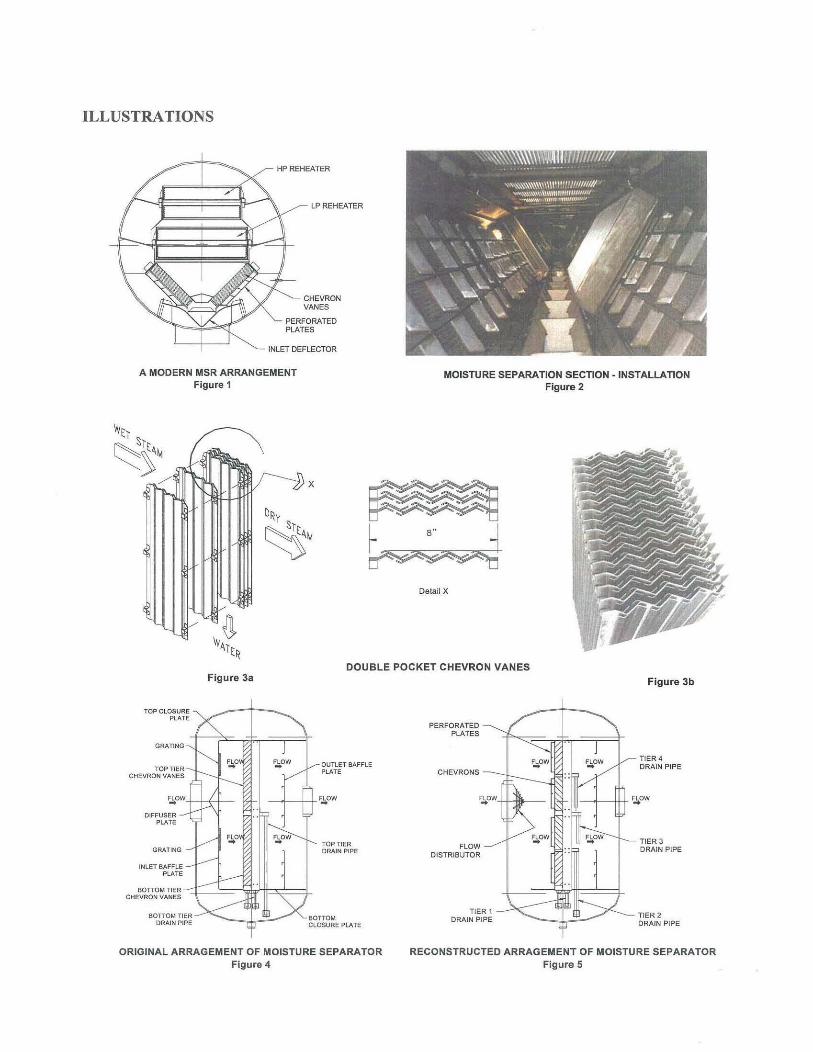
In the first case, there were four, essentially duplicate 820MWe BWRs at the Dresden and Quad Cities plants, builtapproximately 30 years ago. Each incorporated fouroriginal equipment manufacturer (OEM) moistureseparator vessels (MSs), reflecting the design technologyof their time. These MSs are essentially 24-ft (7.3-m) high13-ft (4-m) wide vessels containing four vertical moistureseparator panels which are slightly offset vertically, Fig. 4.At full load, 306 kg/sec (2,432,000 lblhr) of HP turbineoutlet steam at 15.5 BarG (225 psig) and approximately88-percent quality enters each of these MSs and is guidedto the two upper and two lower panels by a V-shapeddeflector, followed by a full-faced baffling plate with twoupper and lower openings, whose distribution effectivenesswas questionable as was their ability to reduce the highturbulence of the incoming steam. There is conclusiveevidence that the dry steam originally anticipated fordelivery to the LP turbine was never really achieved.
While several redesign and reconstruction options existed,optimization pointed to the replacement of the originalsingle-pocket chevron vanes with modem-technologydouble-pocket vanes. One particularly unique obstacle tobe overcome in order to fully utilize the repaired, existinginternal panels was the support structure. The standard,single-pocket, moisture-separation chevron vane panelsproduced 20 or 30 years ago measured 250-mm (IO-in.)
deep by 2.2-m (91-in.) long. Today's, advancedtechnology, double-pocket chevron vane panels are punchproduced to a standard size of 200 mm (8 in.). An earliersolution here involved installing structural spacers in bothdimensions to accommodate the standard new chevronvane panels into the existing support structure.
At Dresden and Quad Cities, all of these MS structuralmodifications and chevron vane panel installations had tobe accomplished through a 600-mm (24-in.) diametermanway into each MS vessel, and installation time waslimited to 16 days. Therefore the installation of perforatedplates was excluded. The initial design target calculatedwas to achieve a 7-MWe gain in each unit. After MSreconstruction, excluding perforated plates, anddiscounting other outage improvements, the actual gain ineach of two plants was I I MWe. The third gained 6.5MWe. The fourth will be retrofitted soon.
Lessons learned ITom these installations lead to significantfurther enhancement of the new design. This also applies toa later version of these old OEM MS vessels with a conicaldistributor instead of a V-shaped deflector and a bafflingplate. These enhancements involved a deeper chevron vanecore blade which extends to 250 mm (10 in.), so as to fitinto the existing support frame with no need forcompensating strips. Restructuring the four-panel, two-tierarrangement into an eight-panel, four-tier arrangementprovides for two additional intermediate drain channelsand shorter chevron vanes, i.e. J m (42 in.). This four-tierarrangement prevents accumulating moisture buildup at thechevron footing and provides ample gravity drainageinside the vessel which is fully vented. Fig. 5.
3 MSR REHEATERS
MSR reheaters have traditionally been fabricated in a widevariety of thermal and physical designs by the variousturbine-generator OEMs over the past 30 years. In eachcase, these design configurations have been intimatelyrelated to the MSR shells and internal structures employed.For example: single-stage (taking heating steam at turbinethrottle temperature and pressure), two-stage (taking bothsteam at throttle temperature and temperature andextraction steam from a mid-point in the HP turbine), asingle tube pass (involving straight tube heat exchanger) 2tube pass (involving a single U-tube heat exchanger), andboth an old- and new-design 4-tube pass (involving a Utube heat exchanger partitioned at its header to create 4passes configurations) are all commonly encountered.Others, such as two V-tube banks connected in seriesthrough a common header and a 6-tube pass configurationhave also been in limited use as original or replacementequipment.
In addition to usually having to take into account thephysical constraints imposed by the MSR shells
themselves, it has occasionally been necessaryeconomically to design around existing internal structuralrequirements. In all cases, however, the overall goals ofMSR reheater redesign and reconstruction remain constant- take full advantage of today's advanced technology interms of physical design and metallurgy, eliminate wastedsteam through minimizing excess purging steam used fortube venting and ineffectual bypass steam control,minimize cycle-steam pressure drop, increase MSR outletsuperheat as much as possible (minimize the terminaltemperature difference (TID». The goal here of course, isto restore MWe lost through the years as a result ofinadequate initial design and/or operational deteriorationovertime, and further enhance MWe output to help meetthe established uprated repowering goals and assurecontinuing operational stability and reliability in the yearsahead.
Regardless of the several constraints frequently restrictingthe complete redesign and reconstruction of MSRreheaters, several steps can almost always be taken toimprove performance and reliability. These include suchthings as optimizing heat transfer by retubing with Type439 stainless steel finned tubes having more (27 per inch)fins. Sometimes this step also involves using differentdiameter tubes and rearranging their geometry, ComanchePeak, Units I and 2, is an example. Many reheater tubedamages and failures, over the years, have resulted fromvariable thermal stresses and physical distortion in theirrigid support structures, due to high temperaturedifferentials. This old design has now been replaced inmany installations by a so-called flexible (slip-plate)support structures, Fig 5, that eliminate these problems. Inaddition, bypass steam losses at the outside tube columnscan be drastically reduced through the use of flowrestricting bars welded to the slip-plates themselves, Fig 6.
Some years ago, it became obvious that a revised 4-passreheater design inherently possessed a distinct operatingadvantage over many of the older installed 4-pass reheaterdesign then installed. Fig. 6 summarizes this essentialarrangement difference. In the old 1-4-3-2 pass design,considerably more steam was required to "drag" theaccumulating condensate up between the 3rd and 4th passes.In the modem 1-3-4-2 pass design, this condensate flowbetween the 3'" and 4'" passes is down, driven by gravityand is con-current with its steam phase. Thus the presenceof excess steam, at this 3'" to 4'" pass point, to drive thecondensate uphill is not required. In addition, modem MSRreconstruction practice call for the installation of a manualcontrol valve at the 4th pass discharge line instead of acommonly used fixed orifice to control the exitingcondensate steam flow. This valve can then be adjustedperiodically to minimize any excess steam flow. Itsadjustment is benchmarked to temperature sensors installedin the tube outlet ends, which provide actual readings.
One example among many of this modem 4-pass redesignand reconstruction feature was carried out some years agoat Duquesne Light's 888-MWe PWR Beaver Valleynuclear power plant. As a result The TTD was reducedfrom 31e" (56Fj down to lie" (20F"). While theexpected output gain was 12 MWe, they actually gained15.6 MWe (including moisture separator efficiencyimprovement and reduction in pressure loss).
Where space permits, older 2-pass reheaters can bereplaced to advantage by advanced design, 4-passreheaters. This was done at the Indiana Michigan PowerCompany's I089-MWe PWR Donald C. Cook NuclearPower Plant, Unit I. Here the TID was reduced fromabout lIe" (I9.8F") to 5Co (9F") and the actual test poweroutput gain was 7 MWe. Figures 7a and 7b show the old2-pass arrangement and the new 4-pass design. Figure 7balso shows the steam/condensate paths which minimizeexcess steam consumption, while increase its relativepurging capability (excess steam ratio).
4 MSR VESSELS
Over time, MSR vessels can suffer severe internal erosionin areas of extremely high steam velocity or highturbulence. In general this damage can be repair welded,but it can be expensive and only temporary. A uniquesituation arose in the redesign and reconstruction of two,954-MWe PWRs at Virginia Power Company's NorthAnna Nuclear Generating Station. In that case, the costsand outage time required to weld-repair the shells wasdeemed to be excessive. It was therefore decided toentirely replace the MSRs with completely factory-builtreplacements. This, of course, allowed the redesign andreconstruction process to take essentially full advantage ofadvanced MSR technology. Thus, the potential for futurecorrosion/erosion damage was eliminated through newdesign and improved metallurgy. This involvedrestructuring the internal flow paths for reducedimpingement, eddies, and turbulence to mtmmlzeerosion/corrosion (EC) as well as utilizing proper materialsto endure EC. In addition, cost-effectiveness of thiscomplete MSR replacement process further benefited fromthe enhanced use of station personnel throughout theinstallation process, the ability to use conventional riggingto bring the complete MSR to the turbine deck, and themain turbine crane to set it in.
A comparison of Figs. 8a and 8b clearly shows how thisdesign freedom was fully utilized in Unit #1 to produce thelatest advanced technology in North Anna's new MSRs.Figure 9 is a photo of one of these completely factory builtMSRs being installed at North Anna. The shell-sidepressure drop was decreased from approximately 158 kPa(22 psi) to negligible 55 kPa (8 psi); the TTD droppedfrom 23Co (4IFO) to a nearly unmeasurable 3Co (5FO); and

an average actual power output gain of 14 MWe wasachieved.
5 MSRINSTALLATION
Field installation of redesigned and reconstructed MSRcomponents - moisture separation elements and reheatersof various configurations - always presents manychallenges. Figure lOis a photo of the reheater installationat KEPCO's Kori 2 unit in Korea. Frequently crampedconditions are encountered in the MSR componentinstallation process. In the first place, time is always acritical element; usually this field work must stay within,or at least minimally exceed, otherwise short scheduledoutage time. This requires an exceptionally high degree ofpre-planning and leans heavily upon the lessons learned In
prior MSR restoration projects. The game plan alwaysincludes contingencies.
Figure II shows the solution to a recent unique problem atSouthern Nuclear's two 820- MWe BWR at Plant Hatch inthe southern US where clear space did not exist towithdraw and lift out, and then re-insert the reheaterbundles. Not only did a wall have to be removed, but alsothe bundle assemblies had to be lowered at an angle,leveled, and only then inserted into the existing shells.
Figures 12a and 12b show another installation problem atthe 975-MWe BWR Cofrentes nuclear power plant inSpain. Here the tube bundles to be removed were not selfsupporting. Hence they had to be removed onto asupporting "tray" at the two levels required for the tworeheater bundles, one above the other, involved per MSRshell.
A very recent innovation in the design and reconstructionof MS sections was successfully carried out at the DuaneArnold Energy Center's 656-MWe BWR in the central US.Since this is a BWR, personnel radiation exposure was animportant consideration in any maintenance operation orcomponent reconstruction operation. To minimizepersonnel radiation exposure during the MSR redesign andreconstruction, structures containing the chevron moistureseparator banks and integral perforated plates wereprefabricated in the factory and shipped as individualmodules to the plant site, Fig 13. In addition to greatlyspeeding up the installation process and minimizingpersonnel radiation exposure, the added benefits of in-shopquality control vs. field assembly within the MSR shell areobvious.
6 ADVANCED MSRs FORTOMORROW'S LARGER NUCLEARPOWER PLANTS
The wide variety and extent of experience gained over thepast 30 years in the redesign, reconstruction, upgrading,and restoration of over 90 MSR sets of essentially everydesign (with the continual application of the lessonslearned) have enahled the nuclear industry world-wide tomeet and overcome the inadequacies in MSRs originallyconsidered to be mere BOP accessories. With this wealthof experience to lean on, and the current appreciation oftheir potentially high impact - for good or bad - in PWRand BWR nuclear power plant cycles, future MSRs willplay an increasing, direct role in plant design.
As nuclear power unit sizes increase by as much as 50percent and more, i.e. from the 1000-MWe range up toperhaps the 1750-MWe range as now being contemplatedin Japan, this 30-year experience becomes invaluahle. Forexample, certainly current MSR physical size cannot bemerely prorated to match unit size increases, nor can amore complex design with multiple shells be physically oreconomically considered as a viable answer. So whatfactors do produce workahle solution?
One is volumetric efficiency increase - the elimination ofwasteful internal structures and the functional use of idle,or residual, space - that must be achieved. A recentexample of this concept was the MSR replacements at theNorth Anna Nuclear Generating Station in Virginia, USAduring its uprating from 900 MWe to 954 MWe. Figure8a, when compared to Fig. 8b, clearly shows how Idlespace was utilized. A wider, octagonal, 4-pass reheater,using a modem configuration replaced the originalrectangular reheater and produced increased performance.Advanced, double-pocket chevron vanes preceded byperforated plates for better wet-steam distributionincreased moisture separation efficiency. One mustremember, however, that many constraints remained atNorth Anna - vessel diameter and length, for example.
This example points up the benefits of the currentrethinking of the place of the MSRs in conceptualizing thelarger nuclear power plants of tomorrow. No longer arethey a mere turbine auxiliaries; they are now a specificallyidentified, major component. Therefore, MSR needs nowplaya major role in large-plant turbine-deck design. This,of course, leads to full MSR performance optimizationbased on the wealth of experience gained over the past 30years.
New, larger nuclear power-plant licensing and predictedplant lives in the 60-year range (essentially doubling thepast's original licensing practices) require very specialattention to those factors that have limited MSR life in thepast. Flow-assisted corrosion (FAC), sometimes called

"wall thinning" or "erosion/corrosion," can no longer betolerated if this extended plant is to be achieved. Thismeans that the steam-flow streamlining lessons learnedover the years with regard to such design refinements, suchas controlling wall-rubbing and gouging steam velocities,areas of frontal steam-flow impingement, and the criticalrelationships between cycle chemistry (stearn/water) andendurance chemistry (carbon, low-alloy, and stainlesssteels) must be carefully considered in future MSRdesigns.Another promising development for possible future use isthe high-velocity moisture separators (HVMSs), Fig. 14.As a "gross" moisture-separation system (increasing steamquality from about 85 percent to as much as 97 percent) inthe HP turbine exhaust piping ahead of the in-vesselchevron-vane, this greatly lightens the hydraulic load onthe in-vessel MS section. In one case, the swirling steamflow in the HVMS centrifugally "throws" the bulk of themoisture to the piping wall where it is peripherallycollected as condensate and, through a loop seal, removedby gravity to a low-pressure receiver. In other cases, asteam feed is needed to induce purging of the condensateinto a valve, controlling its flow to a lower-pressure sump.This possibility of an HVMS-in-series with the in-vesselMS section can have several advantages: (I) It assuresessentially total system moisture removal, and (2) Thepressure drop created by the HVMS can be more thanmade up by reduced losses of the dryer downstream steamflow. Some unsubstantiated reports claim that thistechnology also produces a reduction in piping erosion.
While innovation is an evolving process, care must betaken to avoid unproven design "fads" and confine thisprocess to "mtlking" improvements for all their worth outofproven systems.
As a result of the lessons learned in the past 30 years ofMSR redesign, reconstruction, restoration, and upgradingexperience MSRs stand today at their pinnacle of designand performance as major plant components. Thereforethe nuclear power industry can be confident that the MSRcomponent in the much larger units in the future willperform optimally throughout their extended plant lives.
BIBLIOGRAPHY
G. Loeb, D. Taylor and A.L. Yarden. CommonwealthEdison Upgrading Moisture Separators in Four OlderNPP Units - Gaining 11 MWe In Each of the FirstTwo. EPRI Nuclear Power Plant PerformanceSeminar, August 7-8, 2000.
A.L. Yarden, C.W. Tam, S.T. Deahna and C.V. McFeaters.Reconstruction of the MSRs in Situ at Beaver Valley.Nuclear Engineering International, October 1992.
W.E. Thomas, A.V. Bankley, A.L. Yarden, and C.W. Tam.Complete MSR Replacement at North Anna Eliminates20 Years of FAC Damage, Increases MWe Output.PLlM+PLEX 1999, November 3-5, 1999.
M.R. Price, T.G. Wells, A.L. Yarden and C.W. Tam.Southern Nuclear Integrates MSR Refurbishment WithPower Uprate Program. Power Engineering, April2000.
L.M. Cerezo and A.L. Yarden. Significant MWe Gainsand Unique Installation Challenges in MSR UpgradeProgram at Cofrentes. ASME International JointPower Generation Conference, 1998.
E.S. Sorenson, C.S. Sullivan, A.L. Yarden and C.W. Tam.MSR Upgrade at Duane Arnold Uses Modularizationto Cut Radiation Exposure and Erection Time. ASMEInternational Joint Power Generation Conference, June24-26,2002.
A.L. Yarden and C.W. Tam. The MSR Evolution. NuclearEngineering International, December 1994.
ILLUSTRATIONS
HP REHEATER
LP REHEATER
CHEVRONVANES
PERFORATEDPLATES
INLET DEFLECTOR
A MODERN MSR ARRANGEMENTFigure 1
MOiSTURE SEPARATION SECTION -INSTALLATIONFigure 2
x
Detail X
Figure 3aDOUBLE POCKET CHEVRON VANES
Figure 3b
~OW+-+-<~_
DIFFUSERPLATE
TIER 4DRAIN PIPE~ow
IIII-~f---+J+~OW~OW'+J-HII;--
CHEVRONS
PERFORATEDPLATES
OUTLET BAFFLEPLATE
_+--++F~OW
,",0
GRATING
TOP CLOSUREPLATE
rOPllERCHEVRON VANES
~o
GRATING
~owTOP TIERDRAIN PIPE
FLOWDISTRIBUTOR
~ow ~ow TIER 3DRAIN PIPE
INLET BAFFLEPLATE
BOTTOM T'ER--=t:::::-'=,-(i··n':3~=:j..CHEVRON VANES
BOTTO~ TIERDRAIN PIPE
BOTTOMCLOSURE PLATE
TIER 1DRAIN PIPE
TIER 2DRAIN PIPE
ORIGINAL ARRAGEMENT OF MOISTURE SEPARATORFigure 4
RECONSTRUCTED ARRAGEMENT OF MOISTURE SEPARATORFigure 5

PASSES PASSES
TOTAL MAINHEATING
STEAMADMITTED
L
1 ......3'"
TOTAL MAINHEATING
STEAMADMITTED
L
...
I~
TO DRAIN1-4-3-2 PASS
(OLD)
~ HEATING STEAM
TO DRAIN
mm CONDENSATE
1·3-4-2 PASS(NEW)
4-PASS TUBESIDE ARRANGEMENTSFigure 6
3/4"DIATUBES
EFFECTIVE LENGTH
I PASSES I..3/4~ DIA TUBES
NON_CONDENS~E~~~C~~~~~~~~~~~~STEAM FROM2ND PASS TO
3RDPASS
\...----~
518" DIA. TUBES
HEATING CONDENSATE PRESSURESTEAM IN OUT EQUAL. LINE
Figure 7bFigure 7a
t •• ~HEATING CONDENSATE CONDENSATE PRESSURE
STEAM IN + EXCESS OUT EQUALIZATIONSTEAM OUT LINE
1_== -==® CONDENSATE FORMATION=-- -- IN TUBES
AN ORIGINAL (a) AND AN ADVANCED (b) 4-PASS DESIGNS
STANDARDCAPACITY
REHEATER
STANDARDCAPACITY
CHEVRONS
PERFORATEDPLATES
STEAMMANIFOLD
HIGH CAPACITYREHEATER
HIGH PERFORMANCECHEVRONS
PERFORATEDPLATES
STEAMMANIFOLD
FLOWDEFLECTORS
DRAIN CHANNEL
ORIGINAL MOISTURE SEPARATOR REHEATERFigure Sa
NEW MOISTURE SEPARATOR REHEATERFigure Bb

A NEW MSR VESSEL-INSTALLATIONFigure 9 REPLACEMENT REHEATER -INSTALLATION
Figure 10
~~~~~;::~~~U ~~~;;;;~ :MSR FLOOR:: LEVEL
EWHPEATER
GANTRY CRANE, I-I
-til ~N
REH
NEW REHEATERBUNDLE INSHIPPING CONTAINER
EXISTING COLUMN
LP HEATER~-tI-......:::""_J'ILATFORM
CRANE
EXISTING COLUMN
TURBINE OPERATINGROOM FLOOR
SETUP FOR HOISTING DOWN A NEW LP REHEATER (ENCASED)Figure 11a
SETUP FOR INSTALLATION OF NEW HP BUNDLEFigure 11b
\,,,I
\,,,
REHEATER INSTALlATION - STUDYFlQure 12a
REHEATER INSTALLATiON - ACTUALFigure 12b
SEPARATED WATER
EXTRACTION
INTEGRAL STEAM INJECTlQN
MOISTURE SEPARATION MODULE INSERTIONFigure 13
HIGH VELOCITY MOISTURE SEPARATOR (HVMS)Figure 14


![MSRS Silk Road.ppt [ ۮe Ҧ ])](https://img.pdfslide.net/doc/110x75/62080a07c66d7513ad212043/msrs-silk-roadppt-e-.jpg)