Embed Size (px)
Citation preview
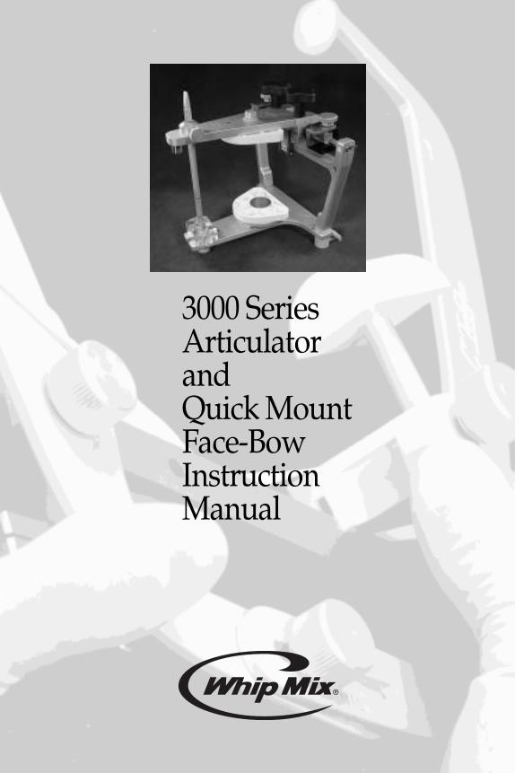
3000 SeriesArticulatorandQuick MountFace-BowInstructionManual
2
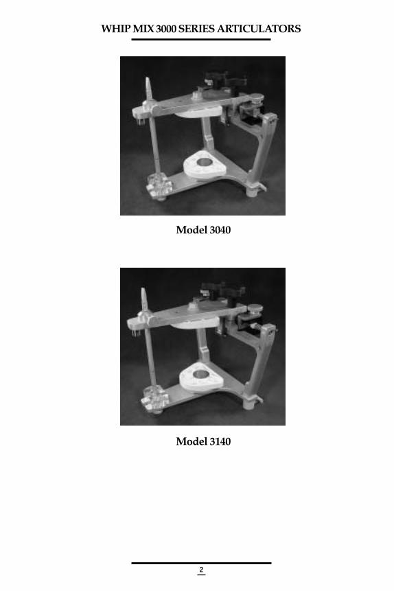
WHIP MIX 3000 SERIES ARTICULATORS
Model 3040
Model 3140
3
CONTENTS
INTRODUCTION 5
OBTAINING FACE-BOW REGISTRATION 6
I. Preparing The Face-Bow 6
II. Preparing The Face-Bow Fork 7
III. Positioning The Face-Bow On The Patient 9
IV. Removing The Face-Bow From The Patient 12
V. Obtaining Interocclusal Records 13
DIRECT MOUNTING THE MAXILLARY CAST ON SERIES 3000 ARTICULATORS 20
I. Preparing The Articulator For Mounting Casts 20
II. Placing A Direct Mounting Face-Bow On The Articulator 23
III. Mounting The Maxillary Cast With A Direct Mounting Face-Bow 25
INDIRECT MOUNTING THE MAXILLARY CAST ON SERIES 3000 ARTICULATORS 28
I. Preparing The Face-Bow And Articulator For Mounting Casts 30
II. Placing The Face-Bow Transfer Assembly On The Articulator 31
III. Mounting The Maxillary Cast 32
MOUNTING THE MANDIBULAR CAST 33
SETTING THE CONDYLAR GUIDANCE OF THE ARTICULATOR 36
TECHNIQUE FOR FABRICATION OF A CUSTOM INCISAL GUIDE TABLE 42
COMPLETE DENTURE TECHNIQUE 43
I. Constructing Occlusion Rims 43
II. Preparing The Face-Bow Fork 43
III. Preparing The Face-Bow Armamentarium 44
IV. Positioning The Face-Bow 44
V. Obtaining Interocclusal Records 45
VI. Preparing The Articulator For Mounting Casts 46
VII. Mounting The Maxillary Cast 46
VIII. Mounting The Mandibular Cast 48
4
IX. Setting The Adjustable Incisal Guide Table 48
X. Obtaining Protrusive Record 49
XI. Fabricating A Remount Index 50
XII. Remounting Casts 51
XIII. Completed Dentures 51
INTERCHANGEABILITY WITH SERIES 3000 ARTICULATORS 52
REMINDERS AND SUGGESTIONS 53
MAINTENANCE 54
SERIES 3000 ARTICULATORS PARTS LISTS 55
Model 3040 Articulator 55
Model 3140 Articulator 56
WHIP MIX FACE-BOWS PARTS LISTS 57-60
Model 8645 Face-Bow (For Direct Mounting) 57
Model 9600 Face-Bow (For Direct Mounting) 58
Models 9175/9185/9195 Face-Bows (For Indirect Mounting) 59
Models 9275/9285/9295 Face-Bows (For Indirect Mounting) 60
BIBLIOGRAPHY 61
5
INTRODUCTION
WHIP MIX Articulators and QUICK MOUNT Face-Bows are designed to enable the user to quickly and easilymount casts of a patient’s dentition on a mechanical device that will reproduce their natural relationship andmovements with an acceptable degree of accuracy. The simplicity and speed with which the necessaryregistrations are obtained and transferred to a WHIP MIX Articulator enable the operator to accomplish correctiveand restorative dentistry with much greater precision than has ever before been possible without the use ofexpensive equipment and time consuming techniques.
For those already using a fully adjustable instrument, a WHIP MIX Articulator serves as an excellent auxiliaryinstrument for diagnostic and patient education purposes, as well as constructing the clutches and recordingdevices needed to secure the proper recordings for setting the more complex instrument. Being arcon typeinstruments, WHIP MIX Articulators are ideal for the study of occlusion and the movements of the temporomandibularjoints. With the condyle located on the lower frame and the guidance on the upper frame (arcon design), WHIPMIX semi-adjustable articulators have become the preferred choice of many teaching institutions. Advancing toa fully adjustable articulator becomes a much easier process after initial training on an arcon semi-adjustablearticulator.
Series 3000 Articulators feature the same sturdy construction and reliability which have been demonstratedsuccessfully in other WHIP MIX Articulator Series. In addition, the following innovative and useful features havebeen incorporated:
• Ergonomic design with wide lingual access and ample interframe distance.
• Tracking condylar guidance with progressive side shift capability.
• An easily positioned centric latch provides a quick wayto return to centric position.
• A permanent intercondylar width of 110 mm — the same as the M settingfound on other WHIP MIX Articulators.
• Elastics provide positive tracking of the condyles during excursivemovements if secured.
• Condyle release mechanisms to prevent accidental separation of thecondyles from the tracking condylar guidance.
• Non-skid rubber feet for stabilizing articulator when open
WHIP MIX Series 3000 Articulators feature the innovative ACCUMOUNT Mounting System ofinterchangeability. This makes it possible to interchange mounted casts between any Series 3000 Articulatorwithout loss of accuracy.
As with other models in the WHIP MIX family of Articulators, a variety of accessories are available.Each Series 3000 Articulator is packaged with the following items:
1 - Instruction Manual 1 - #8580B Plastic Mounting Plate, Set of 2
1 - Serial Number Card
1 - #8580 Metal Mounting Plate, Set of 2
6
OBTAINING FACE-BOW REGISTRATION
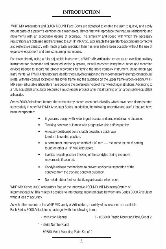
Fig. 1
Items needed for a Face-Bow Registration:1. Face-Bow with Nasion Relator Assembly and Face-Bow Fork (bite fork)2. Compound or Wax Registration Material3. Bard-Parker® Blade or similar instrument
I. Preparing Face-Bows
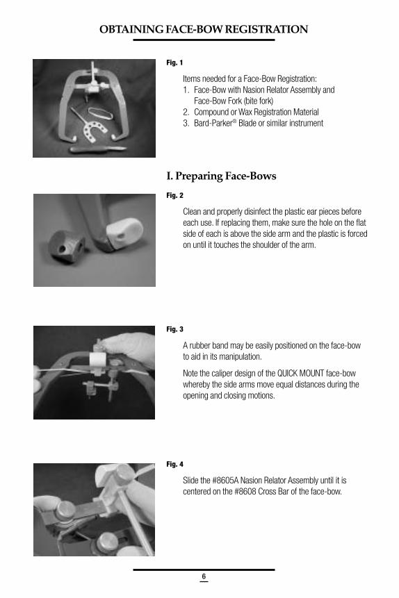
Fig. 2
Clean and properly disinfect the plastic ear pieces beforeeach use. If replacing them, make sure the hole on the flatside of each is above the side arm and the plastic is forcedon until it touches the shoulder of the arm.
Fig. 3
A rubber band may be easily positioned on the face-bowto aid in its manipulation.
Note the caliper design of the QUICK MOUNT face-bowwhereby the side arms move equal distances during theopening and closing motions.
Fig. 4
Slide the #8605A Nasion Relator Assembly until it iscentered on the #8608 Cross Bar of the face-bow.
7
Fig. 5
Loosen the #8604 Thumb Screw on top of the face-bow. Ifusing the Whip Mix metal face-bow you will need to loosenthe three thumb screws on top of the face-bow.
Fig. 6
Loosen the #8640 T-Screw.
Fig. 7
Loosen the #8643 T-Screw.
II. Preparing The Face-Bow Fork
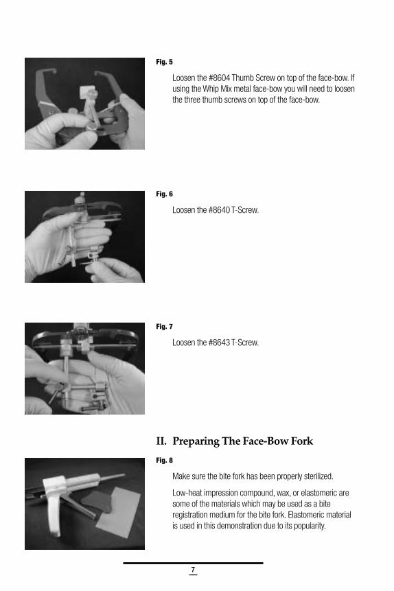
Fig. 8
Make sure the bite fork has been properly sterilized.
Low-heat impression compound, wax, or elastomeric aresome of the materials which may be used as a biteregistration medium for the bite fork. Elastomeric materialis used in this demonstration due to its popularity.
8
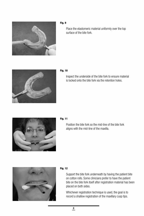
Fig. 9
Place the elastomeric material uniformly over the topsurface of the bite fork.
Fig. 10
Inspect the underside of the bite fork to ensure materialis locked onto the bite fork via the retention holes.
Fig. 11
Position the bite fork so the mid-line of the bite forkaligns with the mid-line of the maxilla.
Fig. 12
Support the bite fork underneath by having the patient biteon cotton rolls. Some clinicians prefer to have the patientbite on the bite fork itself after registration material has beenplaced on both sides.
Whichever registration technique is used, the goal is torecord a shallow registration of the maxillary cusp tips.
9
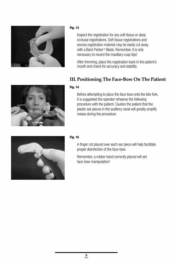
Fig. 13
Inspect the registration for any soft tissue or deepocclusal registrations. Soft tissue registrations andexcess registration material may be easily cut awaywith a Bard-Parker® Blade. Remember, it is onlynecessary to record the maxillary cusp tips!
After trimming, place the registration back in the patient’smouth and check for accuracy and stability.
III. Positioning The Face-Bow On The Patient
Fig. 14
Before attempting to place the face-bow onto the bite fork,it is suggested the operator rehearse the followingprocedure with the patient. Caution the patient that theplastic ear pieces in the auditory canal will greatly amplifynoises during the procedure.
Fig. 15
A finger cot placed over each ear piece will help facilitateproper disinfection of the face-bow.
Remember, a rubber band correctly placed will aidface-bow manipulation!
10
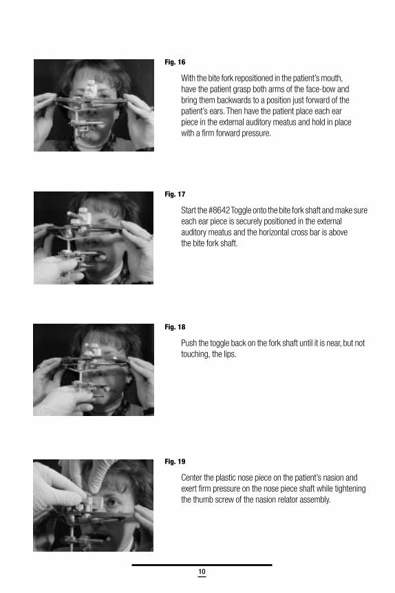
Fig. 16
With the bite fork repositioned in the patient’s mouth,have the patient grasp both arms of the face-bow andbring them backwards to a position just forward of thepatient’s ears. Then have the patient place each earpiece in the external auditory meatus and hold in placewith a firm forward pressure.
Fig. 17
Start the #8642 Toggle onto the bite fork shaft and make sureeach ear piece is securely positioned in the externalauditory meatus and the horizontal cross bar is abovethe bite fork shaft.
Fig. 18
Push the toggle back on the fork shaft until it is near, but nottouching, the lips.
Fig. 19
Center the plastic nose piece on the patient’s nasion andexert firm pressure on the nose piece shaft while tighteningthe thumb screw of the nasion relator assembly.
11
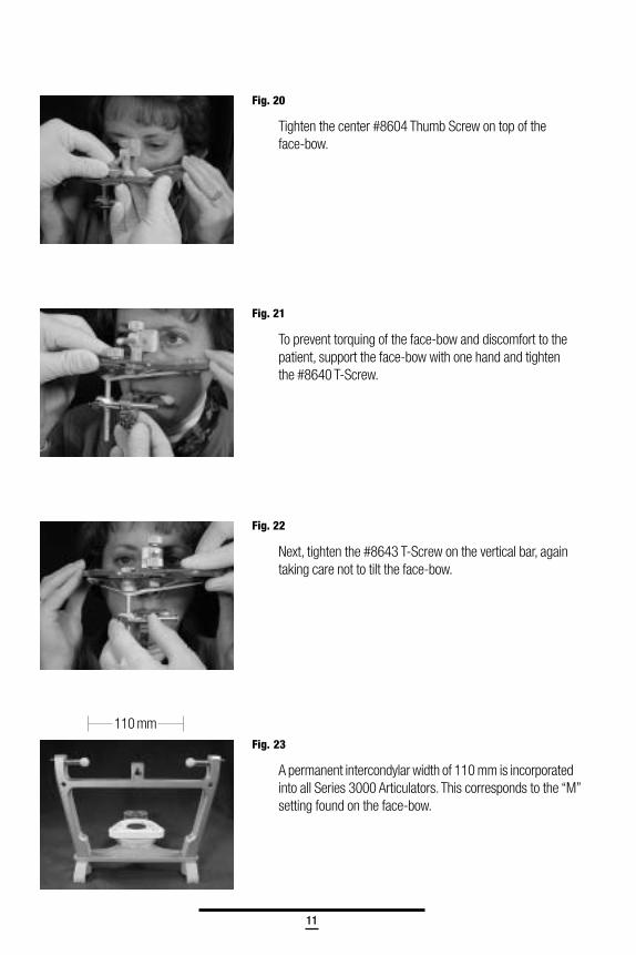
Fig. 20
Tighten the center #8604 Thumb Screw on top of theface-bow.
Fig. 21
To prevent torquing of the face-bow and discomfort to thepatient, support the face-bow with one hand and tightenthe #8640 T-Screw.
Fig. 22
Next, tighten the #8643 T-Screw on the vertical bar, againtaking care not to tilt the face-bow.
Fig. 23
A permanent intercondylar width of 110 mm is incorporatedinto all Series 3000 Articulators. This corresponds to the “M”setting found on the face-bow.
110 mm
12
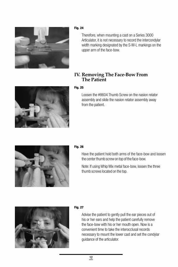
Fig. 24
Therefore, when mounting a cast on a Series 3000Articulator, it is not necessary to record the intercondylarwidth marking designated by the S-M-L markings on theupper arm of the face-bow.
IV. Removing The Face-Bow FromThe Patient
Fig. 25
Loosen the #8604 Thumb Screw on the nasion relatorassembly and slide the nasion relator assembly awayfrom the patient.
Fig. 26
Have the patient hold both arms of the face-bow and loosenthe center thumb screw on top of the face-bow.
Note: If using Whip Mix metal face-bow, loosen the threethumb screws located on the top.
Fig. 27
Advise the patient to gently pull the ear pieces out ofhis or her ears and help the patient carefully removethe face-bow with his or her mouth open. Now is aconvenient time to take the interocclusal recordsnecessary to mount the lower cast and set the condylarguidance of the articulator.
13
V. Obtaining Interocclusal Records
There are several materials available which may be usedto make interocclusal records. There are also differenttechniques and philosophies for making these records.The material selected should complement the particulartechnique used. The technique suggested in this manualis but one method and Whip Mix does not imply that this isthe only technique one can use.
The following interocclusal records (check bites) may beutilized to program the condylar guidance of the articulator:
• Centric Relation and/or Maximum Intercuspation
• Right Lateral
• Left Lateral
• Protrusive (optional)
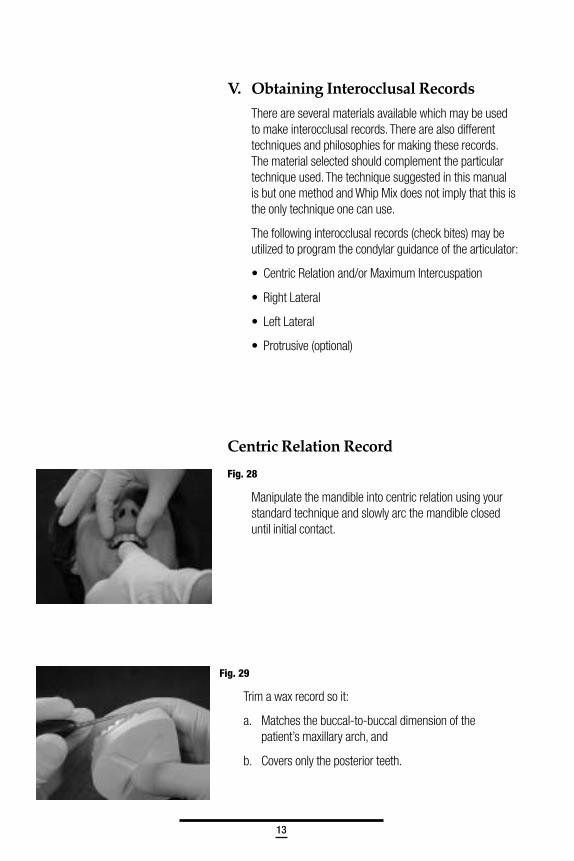
Fig. 28
Manipulate the mandible into centric relation using yourstandard technique and slowly arc the mandible closeduntil initial contact.
Centric Relation Record
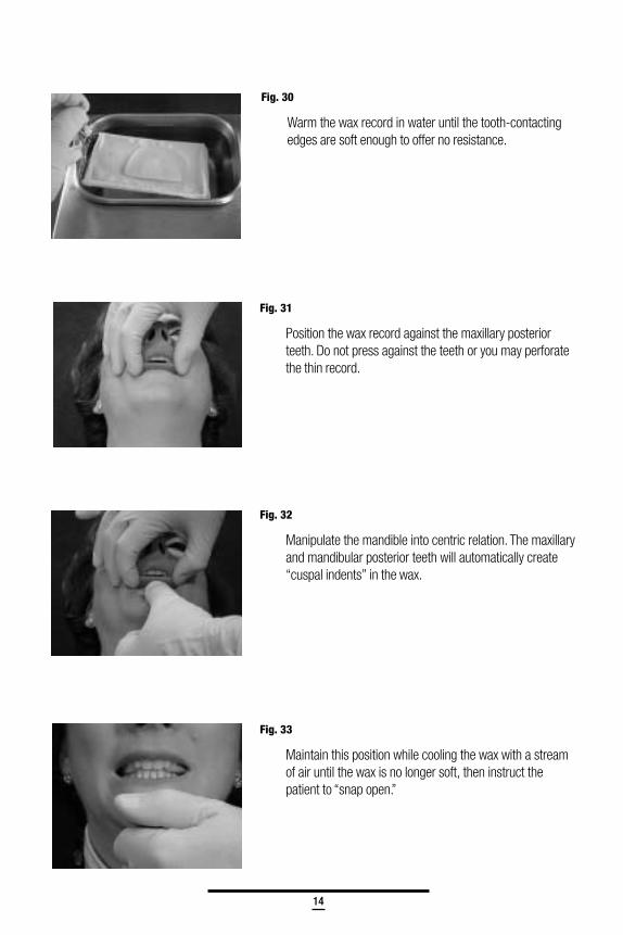
Fig. 29
Trim a wax record so it:
a. Matches the buccal-to-buccal dimension of thepatient’s maxillary arch, and
b. Covers only the posterior teeth.
14
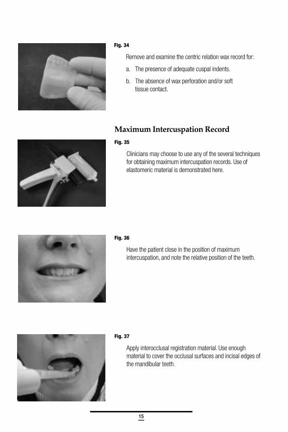
Fig. 30
Warm the wax record in water until the tooth-contactingedges are soft enough to offer no resistance.
Fig. 31
Position the wax record against the maxillary posteriorteeth. Do not press against the teeth or you may perforatethe thin record.
Fig. 32
Manipulate the mandible into centric relation. The maxillaryand mandibular posterior teeth will automatically create“cuspal indents” in the wax.
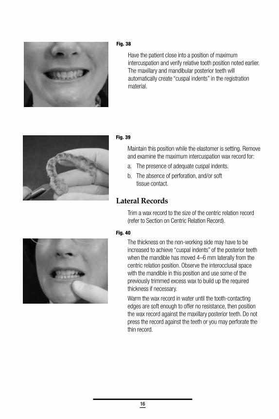
Fig. 33
Maintain this position while cooling the wax with a streamof air until the wax is no longer soft, then instruct thepatient to “snap open.”
15
Fig. 34
Remove and examine the centric relation wax record for:
a. The presence of adequate cuspal indents.
b. The absence of wax perforation and/or softtissue contact.
Maximum Intercuspation Record
Fig. 35
Clinicians may choose to use any of the several techniquesfor obtaining maximum intercuspation records. Use ofelastomeric material is demonstrated here.
Fig. 36
Have the patient close in the position of maximumintercuspation, and note the relative position of the teeth.
Fig. 37
Apply interocclusal registration material. Use enoughmaterial to cover the occlusal surfaces and incisal edges ofthe mandibular teeth.
16
Fig. 38
Have the patient close into a position of maximumintercuspation and verify relative tooth position noted earlier.The maxillary and mandibular posterior teeth willautomatically create “cuspal indents” in the registrationmaterial.
Fig. 39
Maintain this position while the elastomer is setting. Removeand examine the maximum intercuspation wax record for:
a. The presence of adequate cuspal indents.
b. The absence of perforation, and/or softtissue contact.
Lateral Records
Trim a wax record to the size of the centric relation record(refer to Section on Centric Relation Record).
Fig. 40
The thickness on the non-working side may have to beincreased to achieve “cuspal indents” of the posterior teethwhen the mandible has moved 4–6 mm laterally from thecentric relation position. Observe the interocclusal spacewith the mandible in this position and use some of thepreviously trimmed excess wax to build up the requiredthickness if necessary.
Warm the wax record in water until the tooth-contactingedges are soft enough to offer no resistance, then positionthe wax record against the maxillary posterior teeth. Do notpress the record against the teeth or you may perforate thethin record.
17
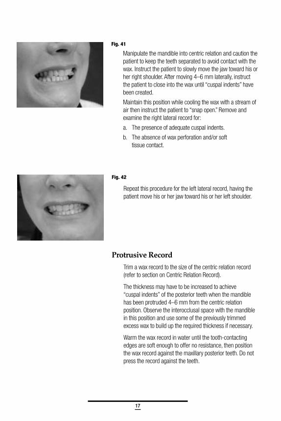
Fig. 41
Manipulate the mandible into centric relation and caution thepatient to keep the teeth separated to avoid contact with thewax. Instruct the patient to slowly move the jaw toward his orher right shoulder. After moving 4–6 mm laterally, instructthe patient to close into the wax until “cuspal indents” havebeen created.
Maintain this position while cooling the wax with a stream ofair then instruct the patient to “snap open.” Remove andexamine the right lateral record for:
a. The presence of adequate cuspal indents.
b. The absence of wax perforation and/or softtissue contact.
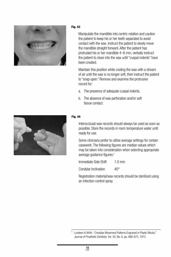
Fig. 42
Repeat this procedure for the left lateral record, having thepatient move his or her jaw toward his or her left shoulder.
Protrusive Record
Trim a wax record to the size of the centric relation record(refer to section on Centric Relation Record).
The thickness may have to be increased to achieve“cuspal indents” of the posterior teeth when the mandiblehas been protruded 4–6 mm from the centric relationposition. Observe the interocclusal space with the mandiblein this position and use some of the previously trimmedexcess wax to build up the required thickness if necessary.
Warm the wax record in water until the tooth-contactingedges are soft enough to offer no resistance, then positionthe wax record against the maxillary posterior teeth. Do notpress the record against the teeth.
18
Fig. 44
Interocclusal wax records should always be used as soon aspossible. Store the records in room temperature water untilready for use.
Some clinicians prefer to utilize average settings for certaincasework. The following figures are median values whichmay be taken into consideration when selecting appropriateaverage guidance figures:1
Immediate Side Shift 1.0 mm
Condylar Inclination 40°
Registration material/wax records should be sterilized usingan infection control spray.
1 Lundeen & Wirth, “Condylar Movement Patterns Engraved in Plastic Blocks,”Journal of Prosthetic Dentistry, Vol. 30, No. 6, pp. 866-875, 1973.
Fig. 43
Manipulate the mandible into centric relation and cautionthe patient to keep his or her teeth separated to avoidcontact with the wax. Instruct the patient to slowly movethe mandible straight forward. After the patient hasprotruded his or her mandible 4–6 mm, verbally instructthe patient to close into the wax until “cuspal indents” havebeen created.
Maintain this position while cooling the wax with a streamof air until the wax is no longer soft, then instruct the patientto “snap open.” Remove and examine the protrusiverecord for:
a. The presence of adequate cuspal indents.
b. The absence of wax perforation and/or softtissue contact.

19
20
I. Preparing The Articulator ForMounting Casts
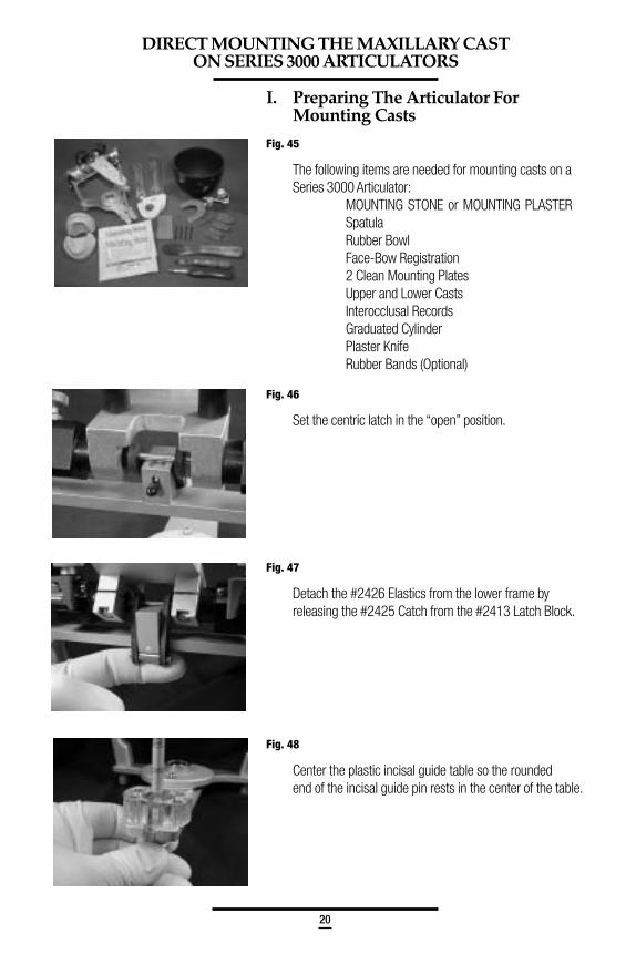
Fig. 45
The following items are needed for mounting casts on aSeries 3000 Articulator:
MOUNTING STONE or MOUNTING PLASTERSpatulaRubber BowlFace-Bow Registration2 Clean Mounting PlatesUpper and Lower CastsInterocclusal RecordsGraduated CylinderPlaster KnifeRubber Bands (Optional)
Fig. 46
Set the centric latch in the “open” position.
Fig. 47
Detach the #2426 Elastics from the lower frame byreleasing the #2425 Catch from the #2413 Latch Block.
Fig. 48
Center the plastic incisal guide table so the roundedend of the incisal guide pin rests in the center of the table.
DIRECT MOUNTING THE MAXILLARY CASTON SERIES 3000 ARTICULATORS
21
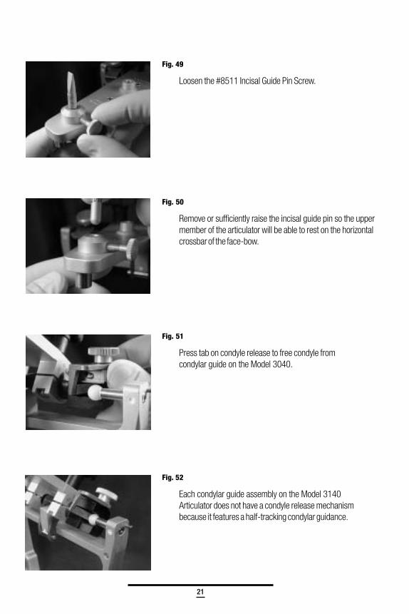
Fig. 49
Loosen the #8511 Incisal Guide Pin Screw.
Fig. 50
Remove or sufficiently raise the incisal guide pin so the uppermember of the articulator will be able to rest on the horizontalcrossbar of the face-bow.
Fig. 51
Press tab on condyle release to free condyle fromcondylar guide on the Model 3040.
Fig. 52
Each condylar guide assembly on the Model 3140Articulator does not have a condyle release mechanismbecause it features a half-tracking condylar guidance.
22
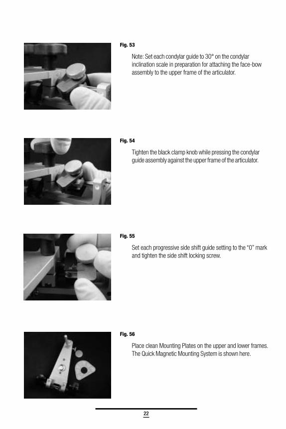
Fig. 53
Note: Set each condylar guide to 30° on the condylarinclination scale in preparation for attaching the face-bowassembly to the upper frame of the articulator.
Fig. 54
Tighten the black clamp knob while pressing the condylarguide assembly against the upper frame of the articulator.
Fig. 55
Set each progressive side shift guide setting to the “0” markand tighten the side shift locking screw.
Fig. 56
Place clean Mounting Plates on the upper and lower frames.The Quick Magnetic Mounting System is shown here.
23
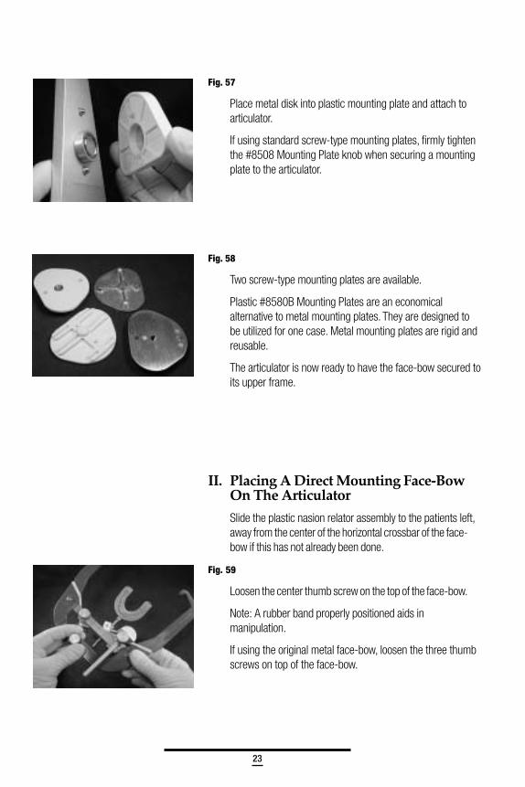
Fig. 57
Place metal disk into plastic mounting plate and attach toarticulator.
If using standard screw-type mounting plates, firmly tightenthe #8508 Mounting Plate knob when securing a mountingplate to the articulator.
Fig. 58
Two screw-type mounting plates are available.
Plastic #8580B Mounting Plates are an economicalalternative to metal mounting plates. They are designed tobe utilized for one case. Metal mounting plates are rigid andreusable.
The articulator is now ready to have the face-bow secured toits upper frame.
II. Placing A Direct Mounting Face-BowOn The Articulator
Slide the plastic nasion relator assembly to the patients left,away from the center of the horizontal crossbar of the face-bow if this has not already been done.
Fig. 59
Loosen the center thumb screw on the top of the face-bow.
Note: A rubber band properly positioned aids inmanipulation.
If using the original metal face-bow, loosen the three thumbscrews on top of the face-bow.
24
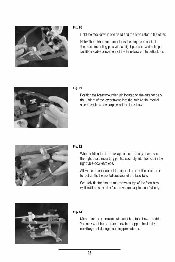
Fig. 61
Position the brass mounting pin located on the outer edge ofthe upright of the lower frame into the hole on the medialside of each plastic earpiece of the face-bow.
Fig. 62
While holding the left-bow against one’s body, make surethe right brass mounting pin fits securely into the hole in theright face-bow earpiece.
Allow the anterior end of the upper frame of the articulatorto rest on the horizontal crossbar of the face-bow.
Securely tighten the thumb screw on top of the face-bowwhile still pressing the face-bow arms against one’s body.
Fig. 63
Make sure the articulator with attached face-bow is stable.You may want to use a face-bow fork support to stabilizemaxillary cast during mounting procedures.
Fig. 60
Hold the face-bow in one hand and the articulator in the other.
Note: The rubber band maintains the earpieces againstthe brass mounting pins with a slight pressure which helpsfacilitate stable placement of the face-bow on the articulator.
25
III. Mounting The Maxillary Cast WithA Direct Mounting Face-Bow
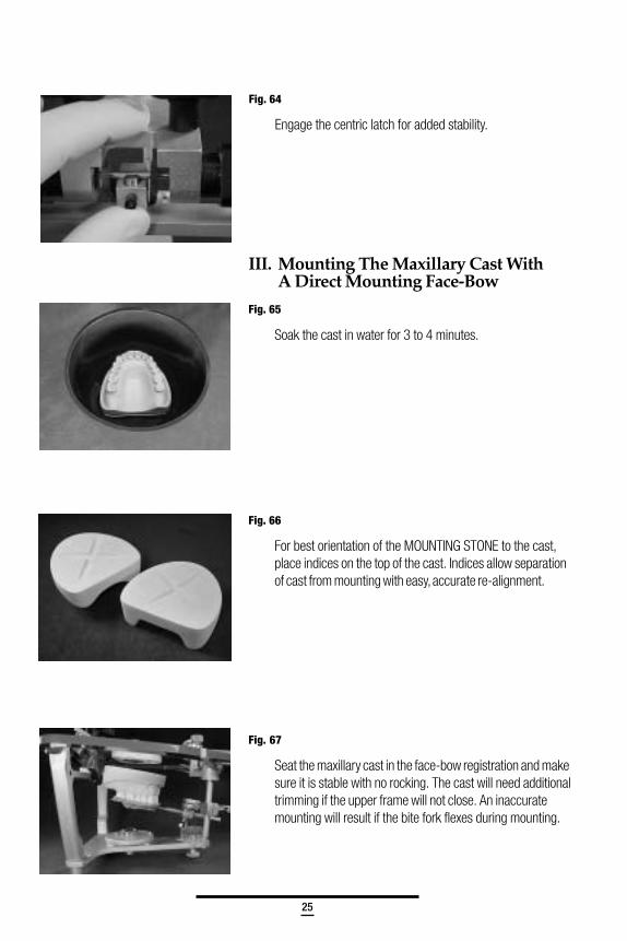
Fig. 65
Soak the cast in water for 3 to 4 minutes.
Fig. 66
For best orientation of the MOUNTING STONE to the cast,place indices on the top of the cast. Indices allow separationof cast from mounting with easy, accurate re-alignment.
Fig. 67
Seat the maxillary cast in the face-bow registration and makesure it is stable with no rocking. The cast will need additionaltrimming if the upper frame will not close. An inaccuratemounting will result if the bite fork flexes during mounting.
Fig. 64
Engage the centric latch for added stability.
26
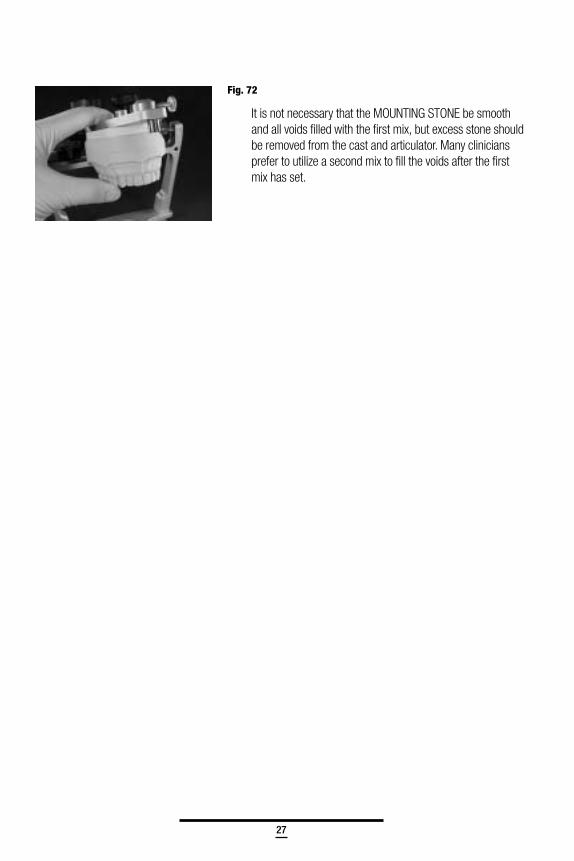
Fig. 69
Whip Mix MOUNTING STONE is ideal for mounting castsbecause it is formulated to have a short working time, greatstacking ability and extremely low setting expansion.
Lift the upper frame of the articulator and apply MOUNTINGSTONE to the base of the cast and the mounting plate.
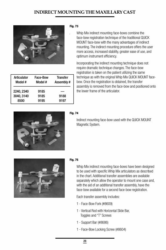
Fig. 70
Close the upper frame to contact the cross bar, bringing theMOUNTING STONE on the two surfaces together. Do not usetoo thick a mix of MOUNTING STONE or attempt to applyforce when the stone has already begun to set. Hold theupper frame in position until the MOUNTING STONE has set.
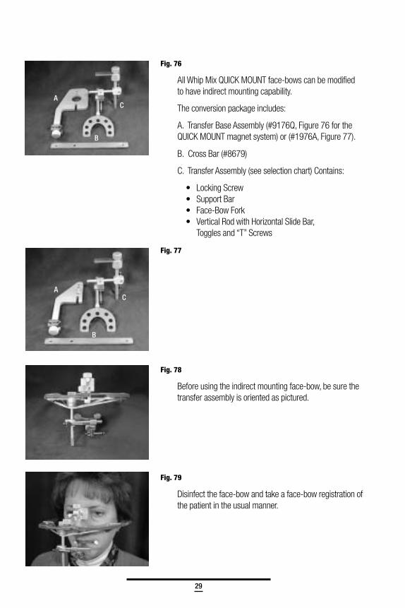
Fig. 71
Carefully remove the face-bow from the articulator.
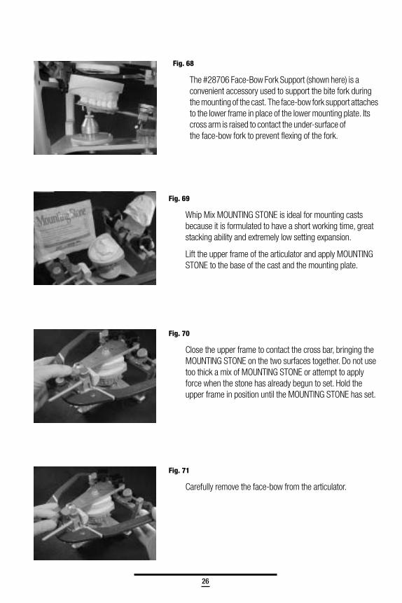
Fig. 68
The #28706 Face-Bow Fork Support (shown here) is aconvenient accessory used to support the bite fork duringthe mounting of the cast. The face-bow fork support attachesto the lower frame in place of the lower mounting plate. Itscross arm is raised to contact the under-surface ofthe face-bow fork to prevent flexing of the fork.
27
Fig. 72
It is not necessary that the MOUNTING STONE be smoothand all voids filled with the first mix, but excess stone shouldbe removed from the cast and articulator. Many cliniciansprefer to utilize a second mix to fill the voids after the firstmix has set.
28
.
INDIRECT MOUNTING THE MAXILLARY CAST
Fig. 73
Whip Mix indirect mounting face-bows combine theface-bow registration technique of the traditional QUICKMOUNT face-bow with the many advantages of indirectmounting. The indirect mounting procedure offers the usermore access, increased stability, greater ease of use, andoptimum instrument efficiency.
Incorporating the indirect mounting technique does notrequire dramatic technique changes. The face-bowregistration is taken on the patient utilizing the sametechnique as with the original Whip Mix QUICK MOUNT face-bow. Once the registration is obtained, the transferassembly is removed from the face-bow and positioned ontothe lower frame of the articulator.
Fig. 74
Indirect mounting face-bow used with the QUICK MOUNTMagnetic System.
Fig. 75
Whip Mix indirect mounting face-bows have been designedto be used with specific Whip Mix articulators as describedin the chart. Additional transfer assemblies are availableseparately which allow the operator to mount one case and,with the aid of an additional transfer assembly, have theface-bow available for a second face-bow registration.
Each transfer assembly includes:
1 - Face-Bow Fork (#8609)
1 - Vertical Rod with Horizontal Slide Bar,Toggles and “T” Screws
1 - Support Bar (#8686)
1 - Face-Bow Locking Screw (#8604)
Articulator Face-Bow TransferModel # Model # Assembly #
2240, 2340 9185 —3040, 3140 9185 9188
8500 9195 9197
29
Fig. 76
All Whip Mix QUICK MOUNT face-bows can be modifiedto have indirect mounting capability.
The conversion package includes:
A. Transfer Base Assembly (#9176Q, Figure 76 for theQUICK MOUNT magnet system) or (#1976A, Figure 77).
B. Cross Bar (#8679)
C. Transfer Assembly (see selection chart) Contains:
• Locking Screw• Support Bar• Face-Bow Fork• Vertical Rod with Horizontal Slide Bar,
Toggles and “T” Screws
Fig. 77
Fig. 78
Before using the indirect mounting face-bow, be sure thetransfer assembly is oriented as pictured.
Fig. 79
Disinfect the face-bow and take a face-bow registration ofthe patient in the usual manner.
A C
B
A
B
C
A
B
C
30
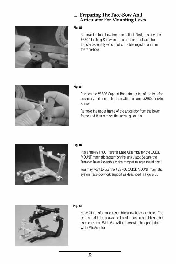
I. Preparing The Face-Bow AndArticulator For Mounting Casts
Fig. 80
Remove the face-bow from the patient. Next, unscrew the#8604 Locking Screw on the cross bar to release thetransfer assembly which holds the bite registration fromthe face-bow.
Fig. 81
Position the #8686 Support Bar onto the top of the transferassembly and secure in place with the same #8604 LockingScrew.
Remove the upper frame of the articulator from the lowerframe and then remove the incisal guide pin.
Fig. 82
Place the #9176Q Transfer Base Assembly for the QUICKMOUNT magnetic system on the articulator. Secure theTransfer Base Assembly to the magnet using a metal disc.
You may want to use the #28706 QUICK MOUNT magneticsystem face-bow fork support as described in Figure 68.
Fig. 83
Note: All transfer base assemblies now have four holes. Theextra set of holes allows the transfer base assemblies to beused on Hanau Wide Vue Articulators with the appropriateWhip Mix Adaptor.
31
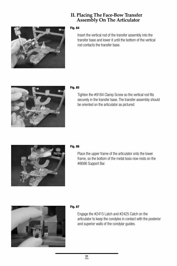
II. Placing The Face-Bow TransferAssembly On The Articulator
Fig. 84
Insert the vertical rod of the transfer assembly into thetransfer base and lower it until the bottom of the verticalrod contacts the transfer base.
Fig. 85
Tighten the #9184 Clamp Screw so the vertical rod fitssecurely in the transfer base. The transfer assembly shouldbe oriented on the articulator as pictured.
Fig. 86
Place the upper frame of the articulator onto the lowerframe, so the bottom of the metal boss now rests on the#8686 Support Bar.
Fig. 87
Engage the #2415 Latch and #2425 Catch on thearticulator to keep the condyles in contact with the posteriorand superior walls of the condylar guides.
32
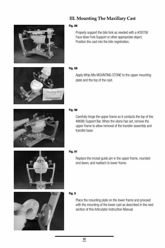
III. Mounting The Maxillary Cast
Fig. 88
Properly support the bite fork as needed with a #28706Face-Bow Fork Support or other appropriate object.Position the cast into the bite registration.
Fig. 89
Apply Whip Mix MOUNTING STONE to the upper mountingplate and the top of the cast.
Fig. 90
Carefully hinge the upper frame so it contacts the top of the#8686 Support Bar. When the stone has set, remove theupper frame to allow removal of the transfer assembly andtransfer base.
Fig. 91
Replace the incisal guide pin in the upper frame, roundedend down, and reattach to lower frame.
Fig. 9
Place the mounting plate on the lower frame and proceedwith the mounting of the lower cast as described in the nextsection of this Articulator Instruction Manual.
33
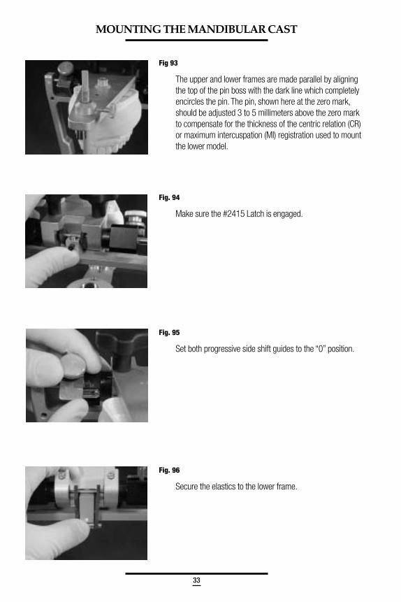
Fig 93
The upper and lower frames are made parallel by aligningthe top of the pin boss with the dark line which completelyencircles the pin. The pin, shown here at the zero mark,should be adjusted 3 to 5 millimeters above the zero markto compensate for the thickness of the centric relation (CR)or maximum intercuspation (MI) registration used to mountthe lower model.
Fig. 94
Make sure the #2415 Latch is engaged.
Fig. 95
Set both progressive side shift guides to the “0” position.
Fig. 96
Secure the elastics to the lower frame.
MOUNTING THE MANDIBULAR CAST
34
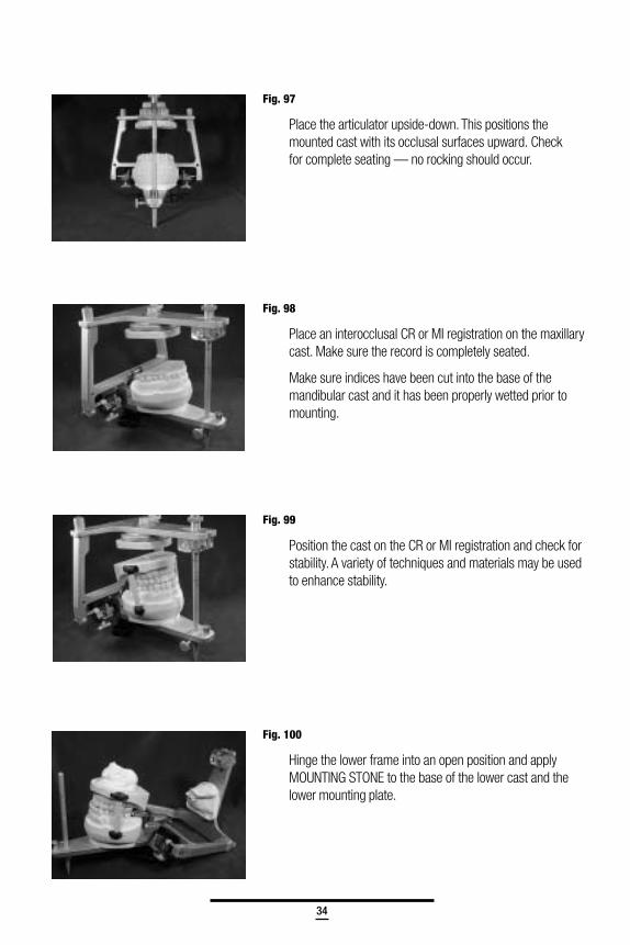
Fig. 97
Place the articulator upside-down. This positions themounted cast with its occlusal surfaces upward. Checkfor complete seating — no rocking should occur.
Fig. 98
Place an interocclusal CR or MI registration on the maxillarycast. Make sure the record is completely seated.
Make sure indices have been cut into the base of themandibular cast and it has been properly wetted prior tomounting.
Fig. 99
Position the cast on the CR or MI registration and check forstability. A variety of techniques and materials may be usedto enhance stability.
Fig. 100
Hinge the lower frame into an open position and applyMOUNTING STONE to the base of the lower cast and thelower mounting plate.
35
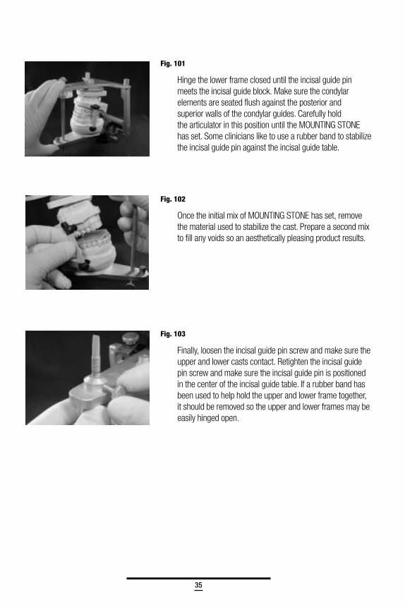
Fig. 101
Hinge the lower frame closed until the incisal guide pinmeets the incisal guide block. Make sure the condylarelements are seated flush against the posterior andsuperior walls of the condylar guides. Carefully holdthe articulator in this position until the MOUNTING STONEhas set. Some clinicians like to use a rubber band to stabilizethe incisal guide pin against the incisal guide table.
Fig. 102
Once the initial mix of MOUNTING STONE has set, removethe material used to stabilize the cast. Prepare a second mixto fill any voids so an aesthetically pleasing product results.
Fig. 103
Finally, loosen the incisal guide pin screw and make sure theupper and lower casts contact. Retighten the incisal guidepin screw and make sure the incisal guide pin is positionedin the center of the incisal guide table. If a rubber band hasbeen used to help hold the upper and lower frame together,it should be removed so the upper and lower frames may beeasily hinged open.
36
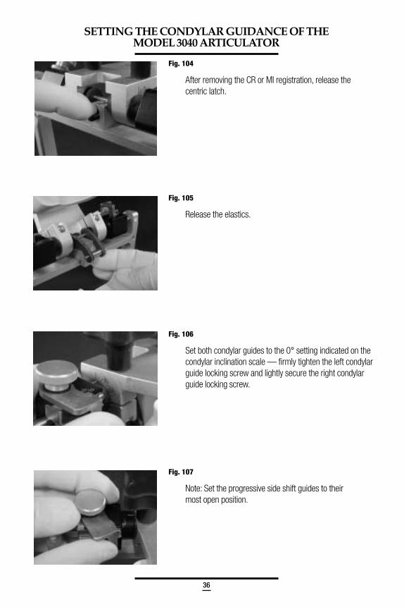
Fig. 104
After removing the CR or MI registration, release thecentric latch.
Fig. 105
Release the elastics.
Fig. 106
Set both condylar guides to the 0° setting indicated on thecondylar inclination scale — firmly tighten the left condylarguide locking screw and lightly secure the right condylarguide locking screw.
Fig. 107
Note: Set the progressive side shift guides to theirmost open position.
SETTING THE CONDYLAR GUIDANCE OF THEMODEL 3040 ARTICULATOR
37
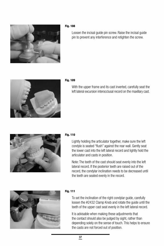
Fig. 108
Loosen the incisal guide pin screw. Raise the incisal guidepin to prevent any interference and retighten the screw.
Fig. 109
With the upper frame and its cast inverted, carefully seat theleft lateral excursion interocclusal record on the maxillary cast.
Fig. 110
Lightly holding the articulator together, make sure the leftcondyle is seated “flush” against the rear wall. Gently seatthe lower cast into the left lateral record and lightly hold thearticulator and casts in position.
Note: The teeth of the cast should seat evenly into the leftlateral record. If the posterior teeth are raised out of therecord, the condylar inclination needs to be decreased untilthe teeth are seated evenly in the record.
Fig. 111
To set the inclination of the right condylar guide, carefullyloosen the #2432 Clamp Knob and rotate the guide until theteeth of the upper cast seat evenly in the left lateral record.
It is advisable when making these adjustments thatthe contact should also be judged by sight, rather thandepending solely on the sense of touch. This helps to ensurethe casts are not forced out of position.
38
Fig. 112
Tighten the #2432 Clamp Knob to secure the guideinto position. DO NOT USE EXCESSIVE PRESSUREwhen tightening the clamp knob.
Fig. 113
To set the right progressive side shift, loosen the right#8520A Side Shift Guide Locking Screw and move the#2405 Right Side Shift Guide until it touches the side ofthe condyle element.
Retighten the right #8520A Screw.
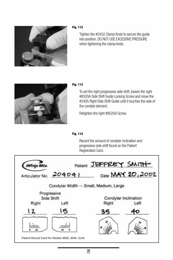
Fig. 114
Record the amount of condylar inclination andprogressive side shift found on the PatientRegistration Card.
Patient Record Card For Models 8500, 3040, 3140.
39
Fig. 115
After the right condylar guidance has been recorded, thecondylar guidance should be neutralized as previouslydescribed. Next, the left condylar guidance is adjusted usingthe right lateral excursion record and repeating the aboveprocedure.
Fig. 116
Many wish to set the condylar inclination of the articulatorwith a protrusive record. To utilize the protrusive record,first neutralize the condylar inclination and progressive sideshift settings. Place the protrusive record on the invertedupper frame of the articulator and gently seat the lowercast into the protrusive record.
Both condylar elements will have moved away fromthe posterior surfaces of their respective condylar guides.
Fig. 117
Using sight and touch, rotate the left condylar guide until theteeth on the left side of the upper cast seat evenly into theprotrusive record, then tighten the #2432 Clamp Knob.Record the reading and repeat the procedure on the rightside. Note: The lateral records are used to determine theprogressive side shift settings.
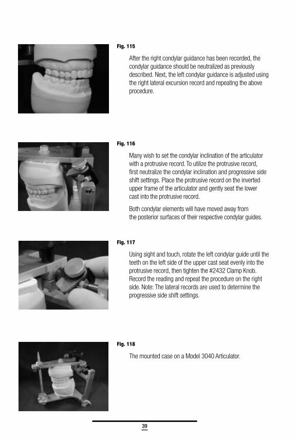
Fig. 118
The mounted case on a Model 3040 Articulator.
40
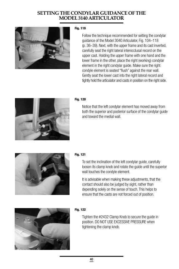
Fig. 119
Follow the technique recommended for setting the condylarguidance of the Model 3040 Articulator, Fig. 104–118(p. 36–39). Next, with the upper frame and its cast inverted,carefully seat the right lateral interocclusal record on theupper cast. Holding the upper frame with one hand and thelower frame in the other, place the right (working) condylarelement in the right condylar guide. Make sure the rightcondyle element is seated “flush” against the rear wall.Gently seat the lower cast into the right lateral record andtightly hold the articulator and casts in position on the right side.
Fig. 120
Notice that the left condylar element has moved away fromboth the superior and posterior surface of the condylar guideand toward the medial wall.
Fig. 121
To set the inclination of the left condylar guide, carefullyloosen its clamp knob and rotate the guide until the superiorwall touches the condyle element.
It is advisable when making these adjustments, that thecontact should also be judged by sight, rather thandepending solely on the sense of touch. This helps toensure that the casts are not forced out of position.
Fig. 122
Tighten the #2432 Clamp Knob to secure the guide inposition. DO NOT USE EXCESSIVE PRESSURE whentightening the clamp knob.
SETTING THE CONDYLAR GUIDANCE OF THEMODEL 3140 ARTICULATOR
41
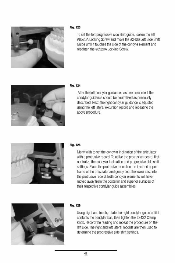
Fig. 123
To set the left progressive side shift guide, loosen the left#8520A Locking Screw and move the #2406 Left Side ShiftGuide until it touches the side of the condyle element andretighten the #8520A Locking Screw.
Fig. 124
After the left condylar guidance has been recorded, thecondylar guidance should be neutralized as previouslydescribed. Next, the right condylar guidance is adjustedusing the left lateral excursion record and repeating theabove procedure.
Fig. 125
Many wish to set the condylar inclination of the articulatorwith a protrusive record. To utilize the protrusive record, firstneutralize the condylar inclination and progressive side shiftsettings. Place the protrusive record on the inverted upperframe of the articulator and gently seat the lower cast intothe protrusive record. Both condylar elements will havemoved away from the posterior and superior surfaces oftheir respective condylar guide assemblies.
Fig. 126
Using sight and touch, rotate the right condylar guide until itcontacts the condylar ball, then tighten the #2432 ClampKnob. Record the reading and repeat the procedure on theleft side. The right and left lateral records are then used todetermine the progressive side shift settings.
42
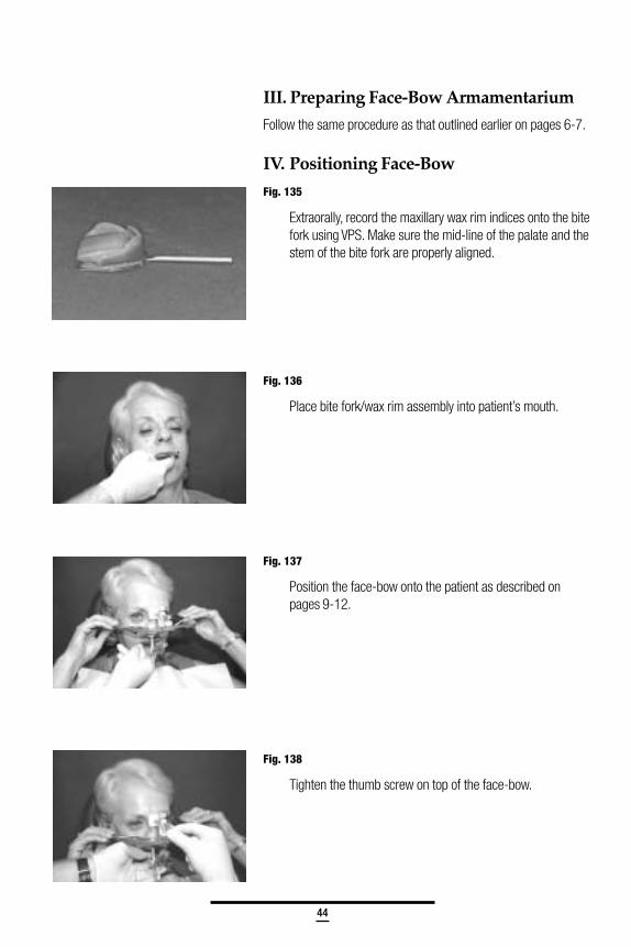
Fig. 129
5. Carefully, close the articulator in centric position.
6. Move the upper frame of the articulator back to simulatea straight protrusive movement (end to end).
7. From centric, move the upper member of the articulatorto give a straight right lateral movement.
8. Then, move the upper member of the articulator togive a straight left lateral movement.
9. Move through all intermediate excursions betweenthe lateral and protrusive positions. Allow the acrylicto harden and trim off excess acrylic.
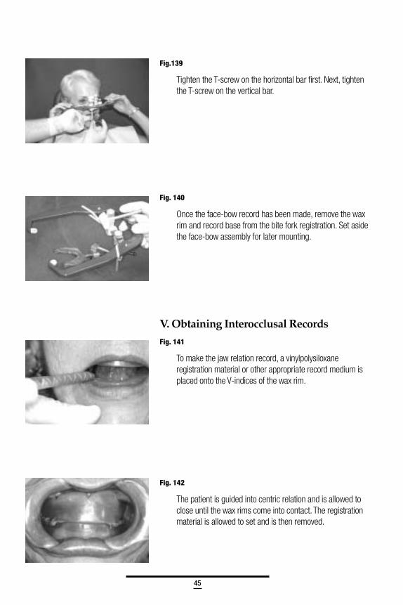
Fig. 130
The #8533 Dovetail Incisal Block is a convenientaccessory designed so a custom acrylic guide may beeasily removed and can later be easily replaced. Itsdovetail sides and centering screw assure the user ofaccurate repositioning time after time.
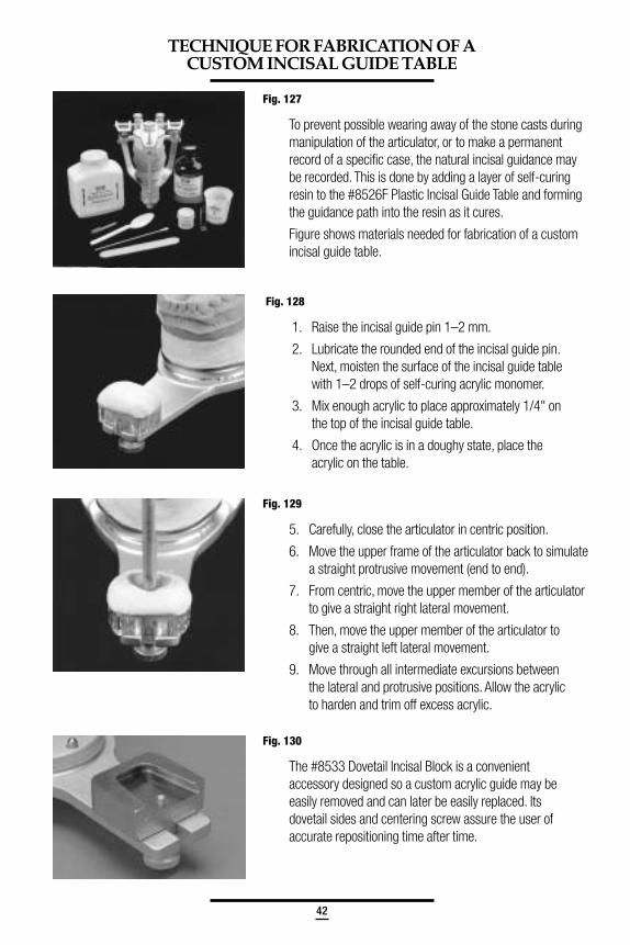
Fig. 127
To prevent possible wearing away of the stone casts duringmanipulation of the articulator, or to make a permanentrecord of a specific case, the natural incisal guidance maybe recorded. This is done by adding a layer of self-curingresin to the #8526F Plastic Incisal Guide Table and formingthe guidance path into the resin as it cures.
Figure shows materials needed for fabrication of a customincisal guide table.
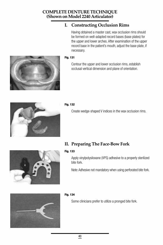
Fig. 128
1. Raise the incisal guide pin 1–2 mm.
2. Lubricate the rounded end of the incisal guide pin.Next, moisten the surface of the incisal guide tablewith 1–2 drops of self-curing acrylic monomer.
3. Mix enough acrylic to place approximately 1/4" onthe top of the incisal guide table.
4. Once the acrylic is in a doughy state, place theacrylic on the table.
TECHNIQUE FOR FABRICATION OF ACUSTOM INCISAL GUIDE TABLE
43
I. Constructing Occlusion Rims
Having obtained a master cast, wax occlusion rims shouldbe formed on well-adapted record bases (base plates) forthe upper and lower arches. After examination of the upperrecord base in the patient’s mouth, adjust the base plate, ifnecessary.
Fig. 131
Contour the upper and lower occlusion rims, establishocclusal vertical dimension and plane of orientation.
Fig. 132
Create wedge-shaped V indices in the wax occlusion rims.
II. Preparing The Face-Bow Fork
Fig. 133
Apply vinylpolysiloxane (VPS) adhesive to a properly sterilizedbite fork.
Note: Adhesive not mandatory when using perforated bite fork.
Fig. 134
Some clinicians prefer to utilize a pronged bite fork.
COMPLETE DENTURE TECHNIQUE(Shown on Model 2240 Articulator)
44
III. Preparing Face-Bow Armamentarium
Follow the same procedure as that outlined earlier on pages 6-7.
IV. Positioning Face-Bow
Fig. 135
Extraorally, record the maxillary wax rim indices onto the bitefork using VPS. Make sure the mid-line of the palate and thestem of the bite fork are properly aligned.
Fig. 136
Place bite fork/wax rim assembly into patient’s mouth.
Fig. 137
Position the face-bow onto the patient as described onpages 9-12.
Fig. 138
Tighten the thumb screw on top of the face-bow.
45
Fig.139
Tighten the T-screw on the horizontal bar first. Next, tightenthe T-screw on the vertical bar.
Fig. 140
Once the face-bow record has been made, remove the waxrim and record base from the bite fork registration. Set asidethe face-bow assembly for later mounting.
V. Obtaining Interocclusal Records
Fig. 141
To make the jaw relation record, a vinylpolysiloxaneregistration material or other appropriate record medium isplaced onto the V-indices of the wax rim.
Fig. 142
The patient is guided into centric relation and is allowed toclose until the wax rims come into contact. The registrationmaterial is allowed to set and is then removed.
46
VI. Preparing The Articulator ForMounting Casts
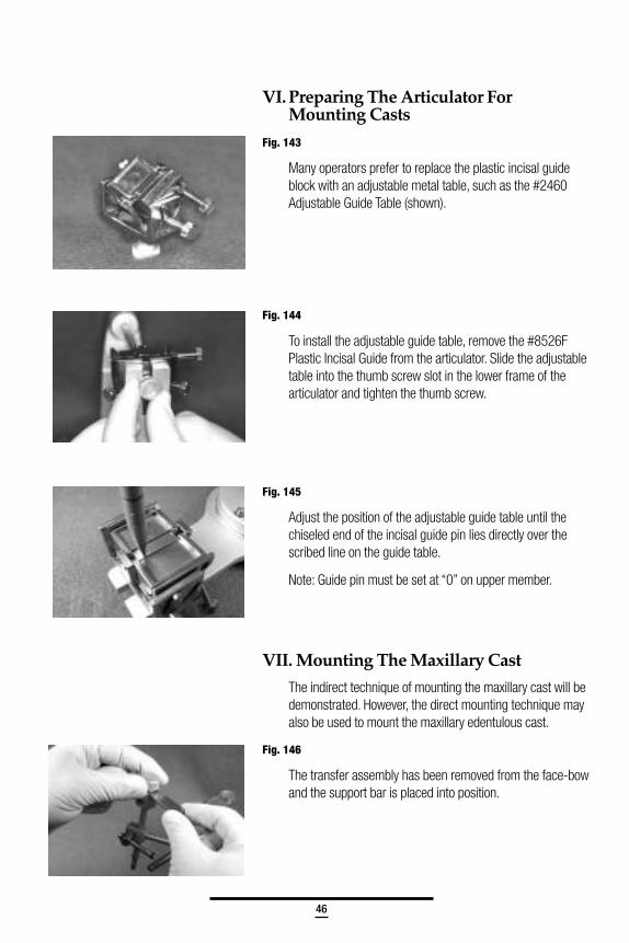
Fig. 143
Many operators prefer to replace the plastic incisal guideblock with an adjustable metal table, such as the #2460Adjustable Guide Table (shown).
Fig. 144
To install the adjustable guide table, remove the #8526FPlastic Incisal Guide from the articulator. Slide the adjustabletable into the thumb screw slot in the lower frame of thearticulator and tighten the thumb screw.
Fig. 145
Adjust the position of the adjustable guide table until thechiseled end of the incisal guide pin lies directly over thescribed line on the guide table.
Note: Guide pin must be set at “0” on upper member.
VII. Mounting The Maxillary Cast
The indirect technique of mounting the maxillary cast will bedemonstrated. However, the direct mounting technique mayalso be used to mount the maxillary edentulous cast.
Fig. 146
The transfer assembly has been removed from the face-bowand the support bar is placed into position.
47
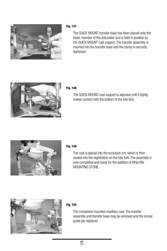
Fig. 147
The QUICK MOUNT transfer base has been placed onto thelower member of the articulator and is held in position bythe QUICK MOUNT cast support. The transfer assembly isinserted into the transfer base and the clamp is securelytightened.
Fig. 148
The QUICK MOUNT cast support is adjusted until it lightlymakes contact with the bottom of the bite fork.
Fig. 149
The cast is placed into the occlusion rim, which is thenseated into the registration on the bite fork. The assembly isnow completed and ready for the addition of Whip MixMOUNTING STONE.
Fig. 150
The completed mounted maxillary cast. The transferassembly and transfer base may be removed and the incisalguide pin replaced.
48
VIII. Mounting The Mandibular Cast
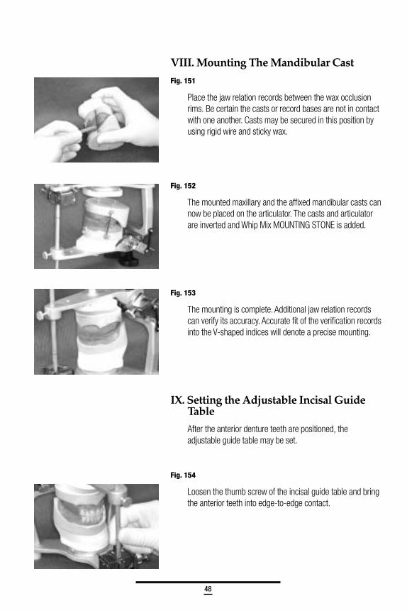
Fig. 151
Place the jaw relation records between the wax occlusionrims. Be certain the casts or record bases are not in contactwith one another. Casts may be secured in this position byusing rigid wire and sticky wax.
Fig. 152
The mounted maxillary and the affixed mandibular casts cannow be placed on the articulator. The casts and articulatorare inverted and Whip Mix MOUNTING STONE is added.
Fig. 153
The mounting is complete. Additional jaw relation recordscan verify its accuracy. Accurate fit of the verification recordsinto the V-shaped indices will denote a precise mounting.
IX. Setting the Adjustable Incisal GuideTable
After the anterior denture teeth are positioned, theadjustable guide table may be set.
Fig. 154
Loosen the thumb screw of the incisal guide table and bringthe anterior teeth into edge-to-edge contact.
49
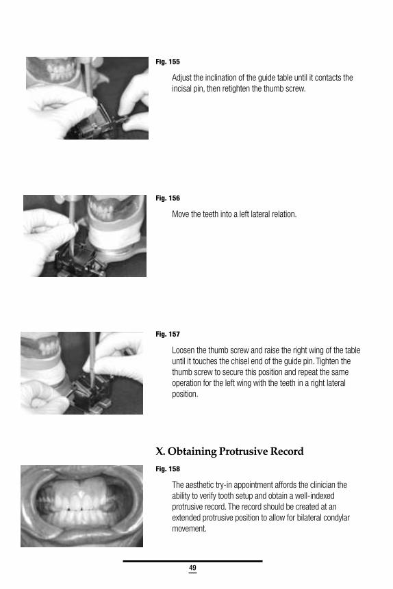
Fig. 155
Adjust the inclination of the guide table until it contacts theincisal pin, then retighten the thumb screw.
Fig. 156
Move the teeth into a left lateral relation.
Fig. 157
Loosen the thumb screw and raise the right wing of the tableuntil it touches the chisel end of the guide pin. Tighten thethumb screw to secure this position and repeat the sameoperation for the left wing with the teeth in a right lateralposition.
X. Obtaining Protrusive Record
Fig. 158
The aesthetic try-in appointment affords the clinician theability to verify tooth setup and obtain a well-indexedprotrusive record. The record should be created at anextended protrusive position to allow for bilateral condylarmovement.
50
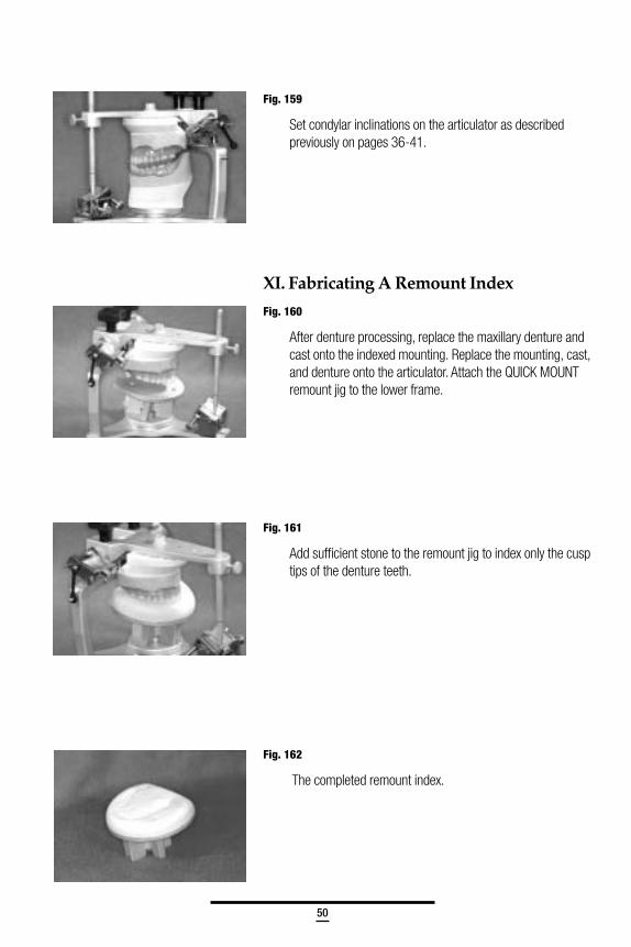
Fig. 159
Set condylar inclinations on the articulator as describedpreviously on pages 36-41.
XI. Fabricating A Remount Index
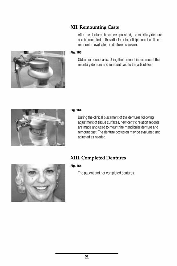
Fig. 160
After denture processing, replace the maxillary denture andcast onto the indexed mounting. Replace the mounting, cast,and denture onto the articulator. Attach the QUICK MOUNTremount jig to the lower frame.
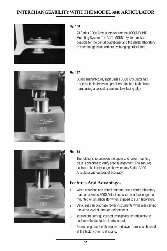
Fig. 161
Add sufficient stone to the remount jig to index only the cusptips of the denture teeth.
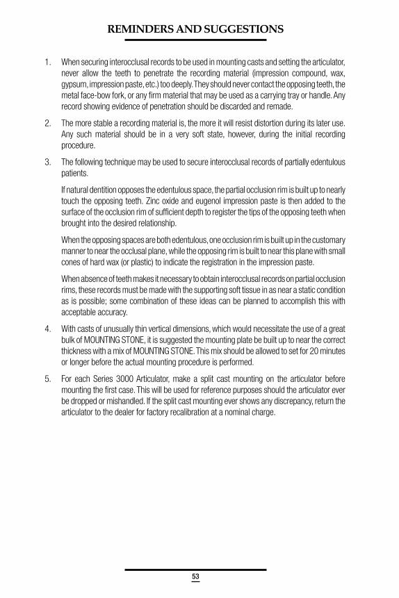
Fig. 162
The completed remount index.
51
XII. Remounting Casts
After the dentures have been polished, the maxillary denturecan be mounted to the articulator in anticipation of a clinicalremount to evaluate the denture occlusion.
Fig. 163
Obtain remount casts. Using the remount index, mount themaxillary denture and remount cast to the articulator.
Fig. 164
During the clinical placement of the dentures followingadjustment of tissue surfaces, new centric relation recordsare made and used to mount the mandibular denture andremount cast. The denture occlusion may be evaluated andadjusted as needed.
XIII. Completed Dentures
Fig. 165
The patient and her completed dentures.
52
Fig. 166
All Series 3000 Articulators feature the ACCUMOUNTMounting System. The ACCUMOUNT System makes itpossible for the dental practitioner and the dental laboratoryto interchange casts without exchanging articulators.
Fig. 167
During manufacture, each Series 3000 Articulator hasa special table firmly and precisely attached to the lowerframe using a special fixture and low-fusing alloy.
Fig. 168
The relationship between the upper and lower mountingplate is checked to verify precise alignment. This assurescasts can be interchanged between any Series 3000Articulator without loss of accuracy.
Features And Advantages
1. When clinicians and dental students use a dental laboratorythat has a Series 3000 Articulator, casts need no longer bemounted on an articulator when shipped to such laboratory.
2. Clinicians can purchase fewer instruments while maintainingthe same level of care for their patients.
3. Instrument damage caused by shipping the articulator toand from the dental lab is eliminated.
4. Precise alignment of the upper and lower frames is checkedat the factory prior to shipping.
INTERCHANGEABILITY WITH THE MODEL 3040 ARTICULATOR
53
REMINDERS AND SUGGESTIONS
1. When securing interocclusal records to be used in mounting casts and setting the articulator,never allow the teeth to penetrate the recording material (impression compound, wax,gypsum, impression paste, etc.) too deeply. They should never contact the opposing teeth, themetal face-bow fork, or any firm material that may be used as a carrying tray or handle. Anyrecord showing evidence of penetration should be discarded and remade.
2. The more stable a recording material is, the more it will resist distortion during its later use.Any such material should be in a very soft state, however, during the initial recordingprocedure.
3. The following technique may be used to secure interocclusal records of partially edentulouspatients.
If natural dentition opposes the edentulous space, the partial occlusion rim is built up to nearlytouch the opposing teeth. Zinc oxide and eugenol impression paste is then added to thesurface of the occlusion rim of sufficient depth to register the tips of the opposing teeth whenbrought into the desired relationship.
When the opposing spaces are both edentulous, one occlusion rim is built up in the customarymanner to near the occlusal plane, while the opposing rim is built to near this plane with smallcones of hard wax (or plastic) to indicate the registration in the impression paste.
When absence of teeth makes it necessary to obtain interocclusal records on partial occlusionrims, these records must be made with the supporting soft tissue in as near a static conditionas is possible; some combination of these ideas can be planned to accomplish this withacceptable accuracy.
4. With casts of unusually thin vertical dimensions, which would necessitate the use of a greatbulk of MOUNTING STONE, it is suggested the mounting plate be built up to near the correctthickness with a mix of MOUNTING STONE. This mix should be allowed to set for 20 minutesor longer before the actual mounting procedure is performed.
5. For each Series 3000 Articulator, make a split cast mounting on the articulator beforemounting the first case. This will be used for reference purposes should the articulator everbe dropped or mishandled. If the split cast mounting ever shows any discrepancy, return thearticulator to the dealer for factory recalibration at a nominal charge.
54
MAINTENANCE
The Whip Mix Model 3040 Articulator is a sturdily constructed instrument that will provide many yearsof service with reasonable care. Both the upper and lower frames are made of cast aluminum. Allaluminum parts are anodized to prevent corrosion or staining. Each condyle element consists of astainless steel shaft and a durable plastic condyle ball. The condylar guide assemblies are made ofanodized aluminum.
• Do not attempt to dislodge or remove the condyle ball from the condyle elementshaft.
• The sealing compound placed over the #2414 Latch Block Mounting Screw,#4415 Set Screws, #8548 Set Screws, and #8507 Screw should not bedisturbed.
• Do not attempt to remove the #2428 Screws holding each condyle releasemechanism.
• Avoid getting wax or stone in the screw holes which may damage the threads.
• Tighten screws snugly, but not too tightly. Overtightening the retaining screws canstrip the threads.
• It is a good idea to use a carrying case when the articulator is transported.Dropping the articulator may result in bent or broken parts which may affect thearticulator’s ability to accurately reproduce a patient’s mandibular movements.
• A thin film of lubricant (Whip Mix LUBRIPLATE) or silicone sprayapplied to the surfaces upon which the condylar elements movewill provide a smooth action of these parts.
• Failing to remove excess stone, or not keeping the articulator clean may result incorrosion of articulator surfaces.
• Apply silicone spray to articulator frame to prevent plaster or stone fromsticking to surfaces.
55
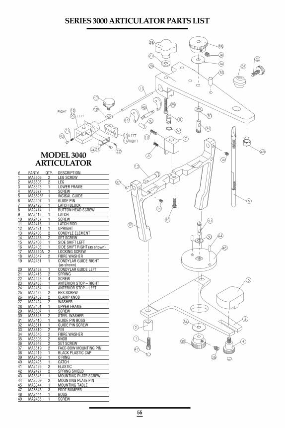
SERIES 3000 ARTICULATOR PARTS LIST
MODEL 3040ARTICULATOR
# PART# QTY. DESCRIPTION1 MA8506 2 LEG SCREW2 MA8505 2 LEG3 MA8343 1 LOWER FRAME4 MA8527 1 SCREW5 MA8526F 1 INCISAL GUIDE6 MA2407 1 GUIDE PIN7 MA2423 1 LATCH BLOCK8 MA2414 1 BUTTON HEAD SCREW9 MA2415 1 LATCH10 MA2437 1 SCREW11 MA2416 1 LATCH ROD12 MA2421 1 UPRIGHT13 MA2408 2 CONDYLE ELEMENT14 MA2438 2 SET SCREW15 MA2406 1 SIDE SHIFT LEFT16 MA2405 1 SIDE SHIFT RIGHT (as shown)17 MA8520A 2 LOCKING SCREW18 MA8547 2 FIBRE WASHER19 MA2451 1 CONDYLAR GUIDE RIGHT
(as shown)20 MA2452 1 CONDYLAR GUIDE LEFT21 MA2418 2 SPRING22 MA2428 4 SCREW23 MA2453 1 ANTERIOR STOP – RIGHT24 MA2454 1 ANTERIOR STOP – LEFT25 MA2422 2 HEX SCREW26 MA2432 2 CLAMP KNOB27 MA2424 2 WASHER28 MA2401 1 UPPER FRAME29 MA8507 1 SCREW30 MA8545 2 STEEL WASHER31 MA2410 1 GUIDE PIN BOSS32 MA8511 1 GUIDE PIN SCREW33 MA8810 2 PIN34 MA8546 2 FIBRE WASHER35 MA8508 2 KNOB36 MA8548 2 SET SCREW37 MA8519 2 FACE-BOW MOUNTING PIN38 MA2419 1 BLACK PLASTIC CAP39 MA2409 1 O RING40 MA2425 1 CATCH41 MA2426 2 ELASTIC42 MA2427 2 SPRING SHIELD43 MA8345 1 MOUNTING PLATE SCREW44 MA8509 2 MOUNTING PLATE PIN45 MA8344 1 MOUNTING TABLE47 MA8543 3 FOOT BUMPER48 MA2444 1 BOSS49 MA2435 1 SCREW
56
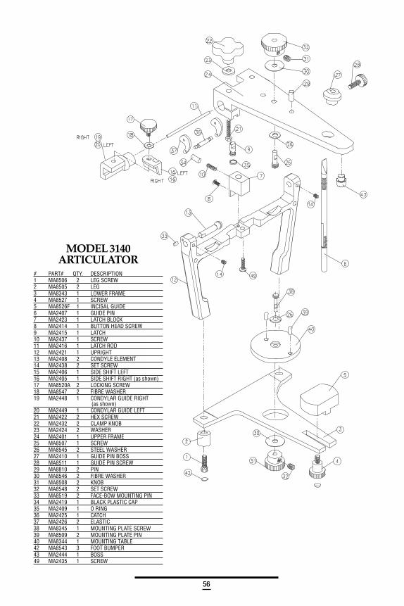
MODEL 3140ARTICULATOR
# PART# QTY. DESCRIPTION1 MA8506 2 LEG SCREW2 MA8505 2 LEG3 MA8343 1 LOWER FRAME4 MA8527 1 SCREW5 MA8526F 1 INCISAL GUIDE6 MA2407 1 GUIDE PIN7 MA2423 1 LATCH BLOCK8 MA2414 1 BUTTON HEAD SCREW9 MA2415 1 LATCH10 MA2437 1 SCREW11 MA2416 1 LATCH ROD12 MA2421 1 UPRIGHT13 MA2408 2 CONDYLE ELEMENT14 MA2438 2 SET SCREW15 MA2406 1 SIDE SHIFT LEFT16 MA2405 1 SIDE SHIFT RIGHT (as shown)17 MA8520A 2 LOCKING SCREW18 MA8547 2 FIBRE WASHER19 MA2448 1 CONDYLAR GUIDE RIGHT
(as shown)20 MA2449 1 CONDYLAR GUIDE LEFT21 MA2422 2 HEX SCREW22 MA2432 2 CLAMP KNOB23 MA2424 2 WASHER24 MA2401 1 UPPER FRAME25 MA8507 1 SCREW26 MA8545 2 STEEL WASHER27 MA2410 1 GUIDE PIN BOSS28 MA8511 1 GUIDE PIN SCREW29 MA8810 2 PIN30 MA8546 2 FIBRE WASHER31 MA8508 2 KNOB32 MA8548 2 SET SCREW33 MA8519 2 FACE-BOW MOUNTING PIN34 MA2419 1 BLACK PLASTIC CAP35 MA2409 1 O RING36 MA2425 1 CATCH37 MA2426 2 ELASTIC38 MA8345 1 MOUNTING PLATE SCREW39 MA8509 2 MOUNTING PLATE PIN40 MA8344 1 MOUNTING TABLE42 MA8543 3 FOOT BUMPER43 MA2444 1 BOSS49 MA2435 1 SCREW
57
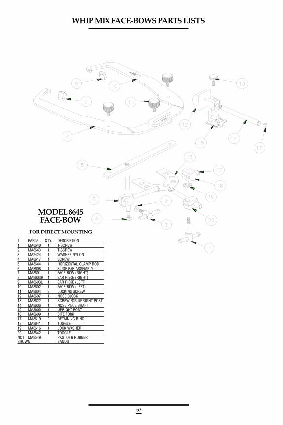
MODEL 8645FACE-BOW
FOR DIRECT MOUNTING
# PART# QTY. DESCRlPTlON1 MA8640 1 T-SCREW2 MA8643 1 T-SCREW3 MA2424 1 WASHER NYLON4 MA8617 1 SCREW5 MA8644 1 HORIZONTAL CLAMP ROD6 MA8608 1 SLIDE BAR ASSEMBLY7 MA8601 1 FACE-BOW (RIGHT)8 MA8603R 1 EAR PIECE (RIGHT)9 MA8603L 1 EAR PIECE (LEFT)10 MA8602 1 FACE-BOW (LEFT)11 MA8604 3 LOCKING SCREW12 MA8607 1 NOSE BLOCK13 MA8622 1 SCREW FOR UPRIGHT POST14 MA8606 1 NOSE PIECE SHAFT15 MA8605 1 UPRIGHT POST16 MA8609 1 BITE FORK17 MA8619 2 RETAINING RING18 MA8641 1 TOGGLE19 MA8616 1 LOCK WASHER20 MA8642 1 TOGGLENOT MA8549 PKG. OF 6 RUBBERSHOWN BANDS
WHIP MIX FACE-BOWS PARTS LISTS
58
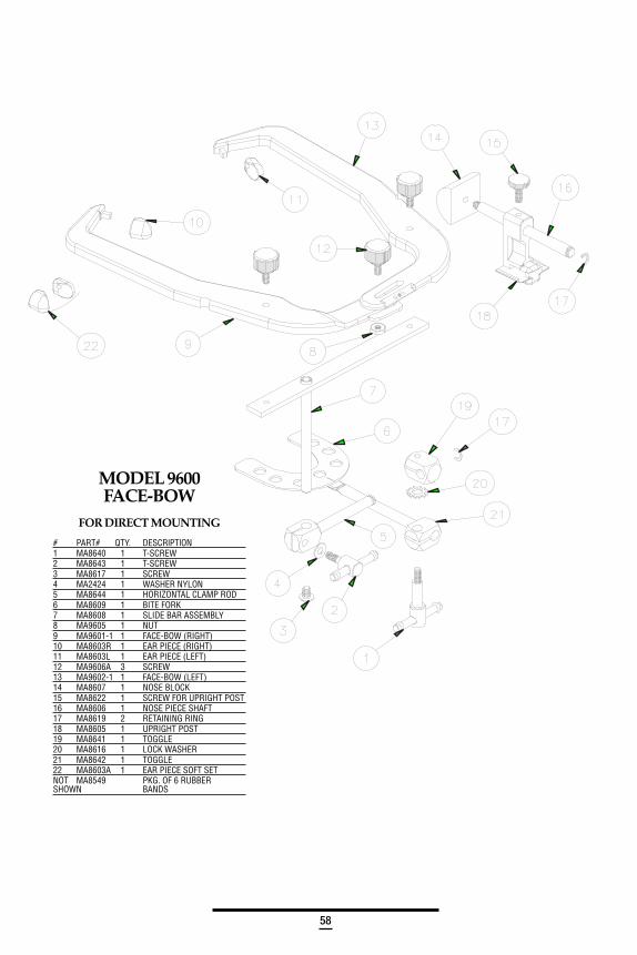
MODEL 9600FACE-BOW
FOR DIRECT MOUNTING
# PART# QTY. DESCRlPTlON1 MA8640 1 T-SCREW2 MA8643 1 T-SCREW3 MA8617 1 SCREW4 MA2424 1 WASHER NYLON5 MA8644 1 HORIZONTAL CLAMP ROD6 MA8609 1 BITE FORK7 MA8608 1 SLIDE BAR ASSEMBLY8 MA9605 1 NUT9 MA9601-1 1 FACE-BOW (RIGHT)10 MA8603R 1 EAR PIECE (RIGHT)11 MA8603L 1 EAR PIECE (LEFT)12 MA9606A 3 SCREW13 MA9602-1 1 FACE-BOW (LEFT)14 MA8607 1 NOSE BLOCK15 MA8622 1 SCREW FOR UPRIGHT POST16 MA8606 1 NOSE PIECE SHAFT17 MA8619 2 RETAINING RING18 MA8605 1 UPRIGHT POST19 MA8641 1 TOGGLE20 MA8616 1 LOCK WASHER21 MA8642 1 TOGGLE22 MA8603A 1 EAR PIECE SOFT SETNOT MA8549 PKG. OF 6 RUBBERSHOWN BANDS

59
MODELS 9175/9185/9195
FACE-BOWSFOR INDIRECT MOUNTINGWITH DB2000/2200/9000/9800
ARTICULATORS
# PART# QTY. DESCRlPTlON1 MA9180 1 SCREW, RD HEAD2 MA9183 1 CLAMP3 MA9182 1 FIXED CLAMP4 MA2424 1 WASHER NYLON5 MA9176 1 TRANSFER BASE6 MA8644 1 HORIZONTAL
CLAMP ROD7 MA8609 1 BITE FORK8 MA9177 1 VERTICAL ROD FOR
#MA9175 FACE-BOWMA9187 1 VERTICAL ROD FOR
#MA9185 FACE-BOWMA9196 1 VERTICAL ROD FOR
#MA9195 FACE-BOW9 MA8686 1 SUPPORT BAR10 MA8679 1 CROSS BAR11 MA8601 1 FACE-BOW (RIGHT)12 MA8603R 1 EAR PIECE (RIGHT)13 MA8603L 1 EAR PIECE (LEFT)14 MA8604 4 LOCKING SCREW15 MA8602 1 FACE-BOW (LEFT)16 MA8622 1 SCREW FOR
UPRIGHT POST17 MA8607 1 NOSE BLOCK18 MA8606 1 NOSE PIECE SHAFT19 MA8605 1 UPRIGHT POST20 MA8619 3 RETAINING RING21 MA8641 1 TOGGLE CLAMP22 MA8616 1 LOCK WASHER23 MA8642 1 TOGGLE CLAMP24 MA8643 1 T-SCREW25 MA8640 1 T-SCREW26 MA9184 1 CLAMP SCREWNOT MA8549 PKG. OF 6 RUBBERSHOWN BANDS
60
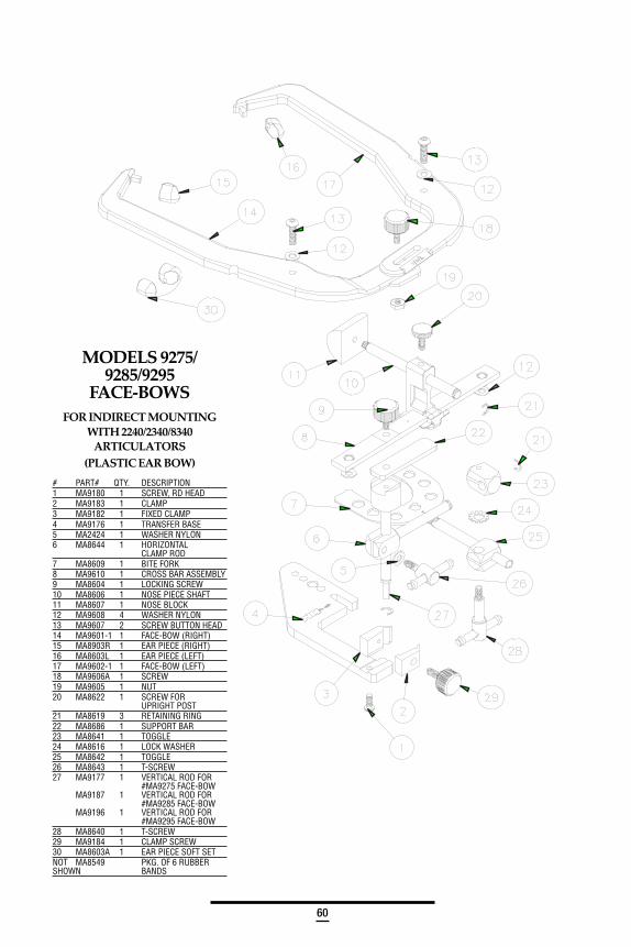
MODELS 9275/9285/9295
FACE-BOWSFOR INDIRECT MOUNTING
WITH 2240/2340/8340ARTICULATORS
(PLASTIC EAR BOW)
# PART# QTY. DESCRlPTlON1 MA9180 1 SCREW, RD HEAD2 MA9183 1 CLAMP3 MA9182 1 FIXED CLAMP4 MA9176 1 TRANSFER BASE5 MA2424 1 WASHER NYLON6 MA8644 1 HORIZONTAL
CLAMP ROD7 MA8609 1 BITE FORK8 MA9610 1 CROSS BAR ASSEMBLY9 MA8604 1 LOCKING SCREW10 MA8606 1 NOSE PIECE SHAFT11 MA8607 1 NOSE BLOCK12 MA9608 4 WASHER NYLON13 MA9607 2 SCREW BUTTON HEAD14 MA9601-1 1 FACE-BOW (RIGHT)15 MA8903R 1 EAR PIECE (RIGHT)16 MA8603L 1 EAR PIECE (LEFT)17 MA9602-1 1 FACE-BOW (LEFT)18 MA9606A 1 SCREW19 MA9605 1 NUT20 MA8622 1 SCREW FOR
UPRIGHT POST21 MA8619 3 RETAINING RING22 MA8686 1 SUPPORT BAR23 MA8641 1 TOGGLE24 MA8616 1 LOCK WASHER25 MA8642 1 TOGGLE26 MA8643 1 T-SCREW27 MA9177 1 VERTICAL ROD FOR
#MA9275 FACE-BOWMA9187 1 VERTICAL ROD FOR
#MA9285 FACE-BOWMA9196 1 VERTICAL ROD FOR
#MA9295 FACE-BOW28 MA8640 1 T-SCREW29 MA9184 1 CLAMP SCREW30 MA8603A 1 EAR PIECE SOFT SETNOT MA8549 PKG. OF 6 RUBBERSHOWN BANDS
61
BIBLIOGRAPHY
The following bibliography gives more background on this instrument system.
Bates, Robert E., Welsch, Boyd B., and Stewart, Carol M.:Temporo Mandibular Joint Disk Position as Determined by a Simple Recorder.J. Pros. Dent., Vol. 56 No. 2, 221-224, 1986.
Cowan, Robert D., Sanchez, R.A., Chappell, R.P., Glaros, A.G., Hayden, W.J.:Verifying the Reliability of Interchanging Casts with Semi-Adjustable Articulators. Inter.J. Pros. Dent., Vol. 4, No. 3, 260-264, 1989.
Lee, Robert L.:Jaw Movements Engraved in Solid Plastic for Articulator Controls. Part 1,Recording Apparatus, J. Pros. Dent., 22:209, 1969.
Lee, Robert L.:Jaw Movements Engraved in Solid Plastic for Articulator Controls. Part II,Transfer Apparatus, J. Pros. Dent., 22:513, 1969.
Loos, Larry:Clinical Criteria Used to Select an Articulator, Compendium, Vol. XIV,No. 1, 80-82, 1993.
Lundeen, Harry C., Wirth, Carl G.:Condylar Movement Patterns Engraved in Plastic Blocks. J. Pros. Dent.,30:866, 1973.
Lundeen, H.C.:An Evaluation of Mandibular Border Movements: Their Character & Significance.J. Pros. Dent., 40:4424-452, 1978.
Lupkiewicz, S.M., Ariet, M., Fujimoto, J., Gibbs, C.H., Lundeen, H.C., & Mahan, R.E.:Reproductibility of Border Movements, Part 1, 2 & 3. IADR Progr. & Abst. 57:No. 367 & 368, 1978.
McCoy, R.B., Shyrock, E.F., & Lundeen, H.C.:A Method of Transferring Mandibular-Movement Data to Computer Storage.J. Pros. Dent., 36:510, 1976.
Sokolow, Stanley M.:Interchangeable Quick-Mounted Study Models. J. Clinical Orthodontics,Vol. XX, No. 11:779-781, 1986.
Welsch, Boyd B.:The Distribution of the Radius of the Curve Scribed During Protrusion.J. Pros. Dent., Vol. 51, No. 4:518, 1984.
Thank you to James T. Dunne, Jr., DMD, MS of the University of Iowa College ofDentistry for his valuable assistance in the production of this manual. Also a
special thank you to the Graduate Prosthodontic Residency Program from theUniversity of Texas Health Science Center at San Antonio Dental School.

For additional information, contact ourTechnical Department at:
MPL 30115 3/03
Whip Mix Corporation361 Farmington Ave.P.O. Box 17183Louisville, KY USA 40217-0183502-637-1451800-626-5651Fax 502-634-4512www.whipmix.com