Embed Size (px)
Citation preview

HandPunch
3000/4000
Manual
ATR Systems, Inc.Time & Labor Management Solutions
Tel: 215.443.8720Fax: [email protected]
P/N: 70100-6003 Version 3.0

This equipment has been tested and found to comply with the limits for a Class B digital device, pursuant to part 15 of the FCC Rules. These limits are designed to provide reasonable protection against harmful interference when the equipment is operated in a commercial environment. This equipment generates, uses, and can radiate radio frequency energy, and, if not installed and used in accordance with the Installation Manual, may cause harmful interference to radio communications. Operation of this equipment in a residential area is likely to cause harmful interference, in which case the user will be required to correct the interference at the user’s own expense.
This Class A digital apparatus meets all requirements of the Canadian Interference-Causing Equipment Regulations.
Cet appareil numerique de la classe A respecte toutes les exigences du Reglemente sure le materiel brouilleur du Canada.
© 1998 through 2003 Recognition Systems, Inc. – ALL RIGHTS RESERVEDDocument Part Number: 70100-6003 – Revision 3 – July, 2003
HandPunch is a trademark of Recognition Systems, Inc.
The trademarks used in this Manual are the property of the trademark holders. The use of these trademarks in this Manual should not be regarded as infringing upon or affecting the validity of any of these trademarks.
Recognition Systems, Inc. reserves the right to change, without notice, product offerings or specifications.
No part of this publication may be reproduced in any form without the express written permission from Recognition Systems, Inc.
Table of Contents
Introduction 3Biometrics 4Principle of Operation 4Specifications 7
Planning an Installation 11Site Preparation 11HandPunch Placement 11
Wiring 12Power Input 12Battery Backup 12Earth Ground and Shielding 13Communications 18External Devices 20Mechanical Installation 23Wall Plate Installation 23Mounting the Wall Plate 24Networking and Communications 27Stand-alone HandReader 27Master or Remote HandReader in a HandReader Network 27Remote HandReader in a HandReader Network Connected to a Host PC 27Remote HandReader Connected to a Host PC via Optional Modem 28Remote HandReader Connected to a Host PC via Optional Ethernet 29Printer 29
Wiring Connections 31
Erasing the Memory 43
Closing the HandPunch 45
Enter Command Menu 47If No One is Enrolled in the HandPunch 47If Users are Enrolled in the HandPunch 47Navigating Command Menus 49
Programming the HandPunch 51Service Menu 54Setup Menu 56Management Menu 60Enrollment Menu 63Special Menu 67
HandPunch Maintenance 69
Appendix A - Installation Tips 71

Appendix B - Differences in Board Layout 73
Appendix C Old Installation Guide 77
Appendix D - Troubleshooting 95
Glossary 97
Limited Warranty 99
HandPunch 3000/4000 Manual
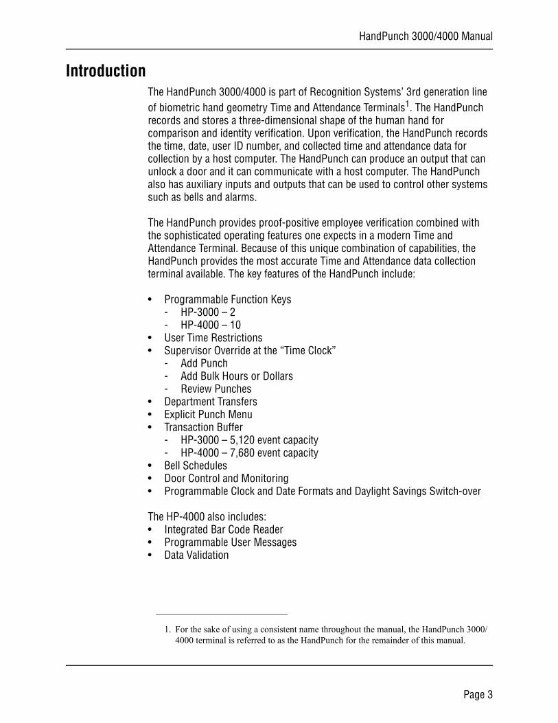
IntroductionThe HandPunch 3000/4000 is part of Recognition Systems’ 3rd generation line of biometric hand geometry Time and Attendance Terminals1. The HandPunch records and stores a three-dimensional shape of the human hand for comparison and identity verification. Upon verification, the HandPunch records the time, date, user ID number, and collected time and attendance data for collection by a host computer. The HandPunch can produce an output that can unlock a door and it can communicate with a host computer. The HandPunch also has auxiliary inputs and outputs that can be used to control other systems such as bells and alarms.
The HandPunch provides proof-positive employee verification combined with the sophisticated operating features one expects in a modern Time and Attendance Terminal. Because of this unique combination of capabilities, the HandPunch provides the most accurate Time and Attendance data collection terminal available. The key features of the HandPunch include:
• Programmable Function Keys- HP-3000 – 2- HP-4000 – 10
• User Time Restrictions• Supervisor Override at the “Time Clock”
- Add Punch- Add Bulk Hours or Dollars- Review Punches
• Department Transfers• Explicit Punch Menu• Transaction Buffer
- HP-3000 – 5,120 event capacity- HP-4000 – 7,680 event capacity
• Bell Schedules• Door Control and Monitoring• Programmable Clock and Date Formats and Daylight Savings Switch-over
The HP-4000 also includes:• Integrated Bar Code Reader• Programmable User Messages• Data Validation
1. For the sake of using a consistent name throughout the manual, the HandPunch 3000/4000 terminal is referred to as the HandPunch for the remainder of this manual.
Page 3
Introduction
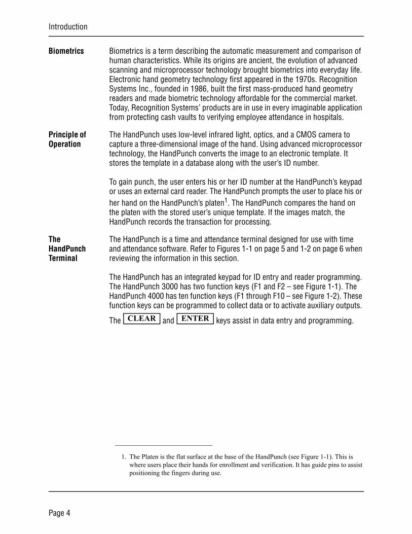
Biometrics Biometrics is a term describing the automatic measurement and comparison of human characteristics. While its origins are ancient, the evolution of advanced scanning and microprocessor technology brought biometrics into everyday life. Electronic hand geometry technology first appeared in the 1970s. Recognition Systems Inc., founded in 1986, built the first mass-produced hand geometry readers and made biometric technology affordable for the commercial market. Today, Recognition Systems’ products are in use in every imaginable application from protecting cash vaults to verifying employee attendance in hospitals.
Principle of Operation
The HandPunch uses low-level infrared light, optics, and a CMOS camera to capture a three-dimensional image of the hand. Using advanced microprocessor technology, the HandPunch converts the image to an electronic template. It stores the template in a database along with the user’s ID number.
To gain punch, the user enters his or her ID number at the HandPunch’s keypad or uses an external card reader. The HandPunch prompts the user to place his or her hand on the HandPunch’s platen1. The HandPunch compares the hand on the platen with the stored user’s unique template. If the images match, the HandPunch records the transaction for processing.
The HandPunch Terminal
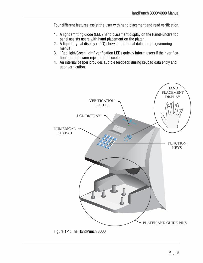
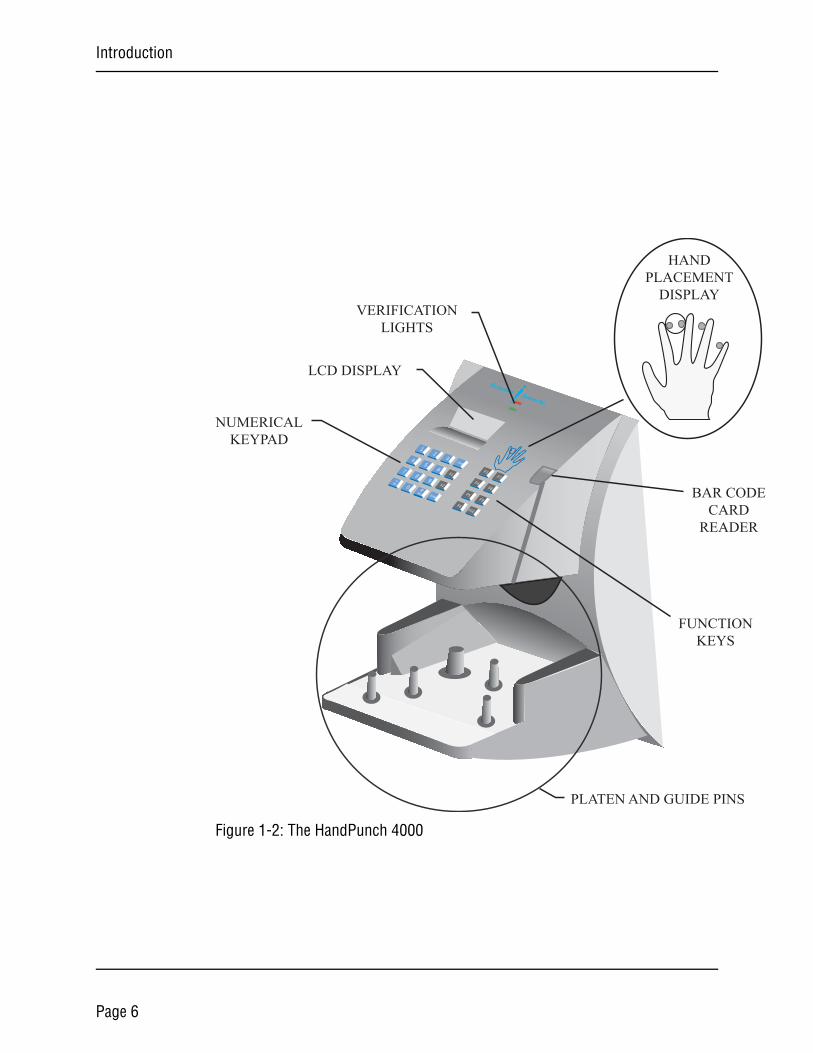
The HandPunch is a time and attendance terminal designed for use with time and attendance software. Refer to Figures 1-1 on page 5 and 1-2 on page 6 when reviewing the information in this section.
The HandPunch has an integrated keypad for ID entry and reader programming. The HandPunch 3000 has two function keys (F1 and F2 – see Figure 1-1). The HandPunch 4000 has ten function keys (F1 through F10 – see Figure 1-2). These function keys can be programmed to collect data or to activate auxiliary outputs.
The and keys assist in data entry and programming.
1. The Platen is the flat surface at the base of the HandPunch (see Figure 1-1). This is where users place their hands for enrollment and verification. It has guide pins to assist positioning the fingers during use.
CLEAR ENTER
Page 4
HandPunch 3000/4000 Manual
S
N
Four different features assist the user with hand placement and read verification.
1. A light emitting diode (LED) hand placement display on the HandPunch’s top panel assists users with hand placement on the platen.
2. A liquid crystal display (LCD) shows operational data and programming menus.
3. “Red light/Green light” verification LEDs quickly inform users if their verifica-tion attempts were rejected or accepted.
4. An internal beeper provides audible feedback during keypad data entry and user verification.
Figure 1-1: The HandPunch 3000
54
6F18
7
9F20
NoEnter
21
3Clear
*#
Yes
No
Recognition Systems Inc.
PLATEN AND GUIDE PIN
HANDPLACEMENT
DISPLAY
LCD DISPLAY
FUNCTIOKEYS
VERIFICATIONLIGHTS
NUMERICALKEYPAD
Page 5
Introduction
S
ON
ODEDER
Figure 1-2: The HandPunch 4000
54
6F18
7
9F20
NoEnter
21
3Clear
*
#Yes
No
Recognition Systems Inc.
PLATEN AND GUIDE PIN
HANDPLACEMENT
DISPLAY
LCD DISPLAY
FUNCTIKEYS
VERIFICATIONLIGHTS
NUMERICALKEYPAD
F5
F6
F3
F4
F9
F10
F7
F8 BAR CCAR
READ
Page 6
HandPunch 3000/4000 Manual
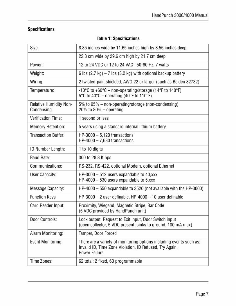
Specifications
Table 1: Specifications
Size: 8.85 inches wide by 11.65 inches high by 8.55 inches deep
22.3 cm wide by 29.6 cm high by 21.7 cm deep
Power: 12 to 24 VDC or 12 to 24 VAC 50-60 Hz, 7 watts
Weight: 6 lbs (2.7 kg) – 7 lbs (3.2 kg) with optional backup battery
Wiring: 2 twisted-pair, shielded, AWG 22 or larger (such as Belden 82732)
Temperature: -10°C to +60°C – non-operating/storage (14°F to 140°F)5°C to 40°C – operating (40°F to 110°F)
Relative Humidity Non-Condensing:
5% to 95% – non-operating/storage (non-condensing)20% to 80% – operating
Verification Time: 1 second or less
Memory Retention: 5 years using a standard internal lithium battery
Transaction Buffer: HP-3000 – 5,120 transactionsHP-4000 – 7,680 transactions
ID Number Length: 1 to 10 digits
Baud Rate: 300 to 28.8 K bps
Communications: RS-232, RS-422, optional Modem, optional Ethernet
User Capacity: HP-3000 – 512 users expandable to 40,xxxHP-4000 – 530 users expandable to 5,xxx
Message Capacity: HP-4000 – 550 expandable to 3520 (not available with the HP-3000)
Function Keys HP-3000 – 2 user definable, HP-4000 – 10 user definable
Card Reader Input: Proximity, Wiegand, Magnetic Stripe, Bar Code(5 VDC provided by HandPunch unit)
Door Controls: Lock output, Request to Exit input, Door Switch input(open collector, 5 VDC present, sinks to ground, 100 mA max)
Alarm Monitoring: Tamper, Door Forced
Event Monitoring: There are a variety of monitoring options including events such as: Invalid ID, Time Zone Violation, ID Refused, Try Again,Power Failure
Time Zones: 62 total: 2 fixed, 60 programmable
Page 7
Introduction
Options HandPunch units have the following options available.
• Backup Battery Support See Technical Note 70200-0012 – Rev. D
• Modem Communication See Technical Note 70200-0013 – Rev. D
• Ethernet Communication See Technical Note 70200-0014 – Rev. D
Recommended European Power Supply1:
Ault, Inc.7300 Boone Ave. NorthMinneapolis, MN 55428 USAPH: 612-493-1900E-mail: [email protected]
Part number: D48-121000-A040G230 VAC Input, 12 VDC @ 1Amp output (unregulated)Ault style #41 connector (barrel plug)
Time Schedules: HP-4000 – 3 definable time schedules per user
Auxiliary Inputs 2 (open collector, 5 VDC present, sinks to ground, 100 mA max)
Auxiliary Outputs up to 3 user definable(open collector, 5 VDC present, sinks to ground, 100 mA max)
Table 1: Specifications
1. Not evaluated by UL for UL 294 installations.
approved
recyclable
Page 8

HandPunch 3000/4000 Manual
UL Compliance
The HP-3000 and HP-4000 meet UL compliance requirements for UL 294 Access Control Systems under this condition:
1. The HandPunch is configured at the factory with a Wiegand output that enables the HandPunch to communicate with an access control panel. The access control panel controls the locking and unlocking of the door. The panel must reside on the secure side of the facility.
Page 9

Introduction
This page is intentionally blank.
Page 10
HandPunch 3000/4000 Manual
Planning an Installation
Site Preparation
Before you begin installation, check the site blueprints, riser diagrams, and specifications for important information about the HandPunch’s location and other systems that will connect to the HandPunch. Look for any existing wall preparations and wiring that other contractors may have installed for the HandPunch. A wire routing layout diagram (see Figure 3-2 on page 25) is provided to assist in planning.
HandPunch Placement
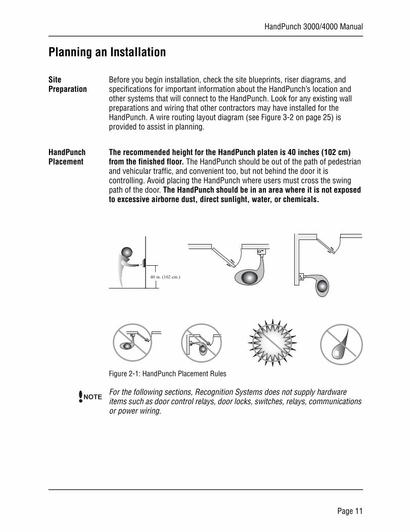
The recommended height for the HandPunch platen is 40 inches (102 cm) from the finished floor. The HandPunch should be out of the path of pedestrian and vehicular traffic, and convenient too, but not behind the door it is controlling. Avoid placing the HandPunch where users must cross the swing path of the door. The HandPunch should be in an area where it is not exposed to excessive airborne dust, direct sunlight, water, or chemicals.
Figure 2-1: HandPunch Placement Rules
For the following sections, Recognition Systems does not supply hardware items such as door control relays, door locks, switches, relays, communications or power wiring.
40 in. (102 cm.)
NOTE
Page 11
Planning an Installation
WiringFour basic circuits typically connect to the HandPunch:• Power Input• Earth Ground and Shielding• Networking and Communications• External Devices
The minimum wire size for these circuits is AWG 22; the maximum wire size is AWG 18. RSI recommends using Belden 82732 or its equivalent when wiring for RS-422 communications.
Power Input The HandPunch uses an internal switching regulator to obtain internal
operational power. It accepts input voltages from 12 to 24 VDC or 12 to 24 VAC at 50 to 60 Hz. The HandPunch comes with a 120 VAC to 13.5 VDC power supply (Class 2, Model No. P48131000A010G-120 VAC, 60 Hz, 21 W, 13.5 VDC output @ 1000mA), if need an optional 220 VDC power supply is also available (this power supply was not evaluated for UL 294).
To power the HandPunch with this power supply, a 120 VAC (or 220 VAC as applicable) duplex outlet must be within 5 feet of the HandPunch. The power supply has a 6-foot cable to provide a comfortable reach between power outlet and HandPunch. The barrel jack at the of the power supply’s cable is connected to J12 on the HandPunch PCB.
J6 terminal 1 and the center pin of power jack J12 are connected together. J6 terminal 2 and the sleeve of power jack J12 are connected together.
Neither terminal 1 or terminal 2 is connected to the HandPunch ground.
Do not connect a HandPunch's power supply to a switched duplex outlet. The HandPunch must have a constant source of power for proper operation.
Battery Backup
The HandPunch uses an internal switching regulator to obtain internal operational power. It accepts input voltages from 12 to 24 VDC or 12 to 24 VAC at 50 to 60 Hz. An optional power-fail protection circuit board can be attached to the main circuit board to provide and control battery backup. The design of the internal power supply is such that any range of the above input voltages may be used and still provide proper battery charge voltage and battery backup operation. Switch-over to battery power is automatic and occurs when the input voltage falls to approximately 10.5 volts. At that time the internal battery charger is disabled to save power and uninterrupted operation continues on battery power.
NOTE
NOTE
NOTE
Page 12
HandPunch 3000/4000 Manual
When input power is restored, the HandPunch switches off of battery operation and the battery charger is re-enabled to recharge the battery. Battery charge voltage is set at approximately 13.65 volts, and battery charge current is limited to approximately 50 mA. A fully discharged battery requires approximately 12 hours of charge to fully recover.
Additional options installed and specific configurations within the HandPunch make it difficult to predict precisely how long battery support will last, but in general two hours of battery operation can be expected. While operating on battery backup due to loss of main input power, the battery output voltage is constantly monitored by internal circuitry. If the battery voltage reaches approximately 9.5 volts the HandPunch automatically shuts down. This is done to prevent full exhaustion of the battery. A yellow indicator on the top panel illuminates to indicate that the HandPunch is running off of battery power. This indicator extinguishes when main input power is restored.
Shunt J7 which is located to the left of TS3 see Figure 4-1 on page 27 enables or disables battery operation on those HandPunchs equipped with optional battery backup. If a HandPunch does not have the optional battery backup package installed, J7 is not used. On HandPunchs equipped with the battery backup option, J7 allows service personnel a mechanism for disabling battery backup operation before removal of main input power. To fully power down a HandPunch equipped with battery backup, remove or reposition shunt J7 so that the two pins protruding up from the main logic board are not connected to each other. This effectively opens the circuit, removing the battery from any internal circuitry. Main input power can then be removed and the HandPunch will fully shut down. Once the HandPunch has fully shut down, shunt J7 may be reinstalled. The design of the power supply is such that main input power must be reapplied to re-enable the battery protection mechanism. If shunt J7 is not properly installed, the internal backup battery will not be charged, and in the event of a main input power loss, the HandPunch will shut down.The HandPunch with the battery backup option uses a 12 volt 800 ma/hour sealed lead acid battery to provide backup battery power. This battery is located immediately inside the rear panel of the HandPunch and plugs into jack J4 on the keypad control circuit board located in the top of the chassis.
Earth Ground and Shielding
Recognition Systems recommends that all HandPunchs be grounded with a solid, reliable earth ground connection. This connection establishes a common ground return point used to protect internal semiconductor devices from ElectroStatic Discharge (ESD) and from external signal line transients. It also provides a common signal level reference point between externally networked HandPunchs. Recognition Systems recommends that the earth ground source
Page 13
Planning an Installation
be identified by a qualified electrician familiar with electrical codes as well as wiring and grounding techniques.
This is an extremely important and often overlooked aspect of hard-wired serial communication systems. If the sending and receiving stations do not agree on the ground reference for the signal voltages, communication errors or a total inability to communicate may be observed. If the voltages are very different, it is even possible to damage the units.
The subject of grounding can be complicated, and the full circuit of a system, including power supplies and often even the building line power wiring, must be understood. It is strongly recommended that a qualified electrician or electrical engineer familiar with this subject be consulted when designing the wiring of an HGU network installation. Always adhere to any applicable electrical codes for your area. Recognition Systems is not responsible for damage done to units due to improper wiring.
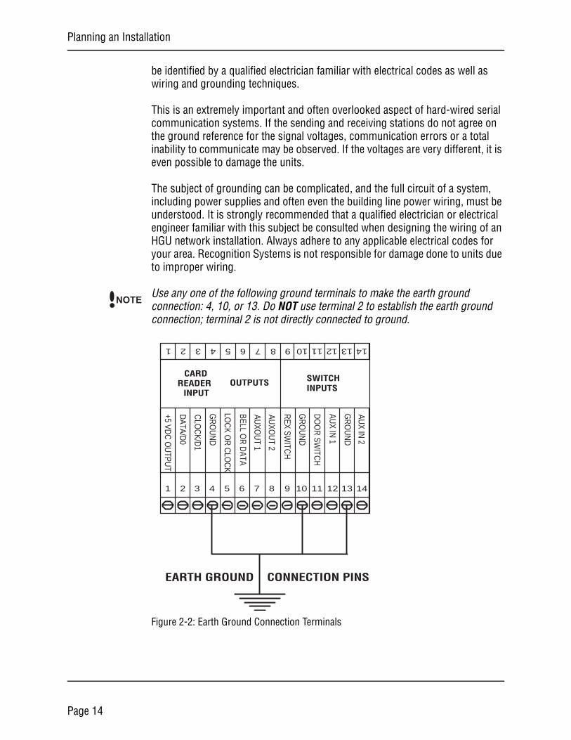
Use any one of the following ground terminals to make the earth ground connection: 4, 10, or 13. Do NOT use terminal 2 to establish the earth ground connection; terminal 2 is not directly connected to ground.
Figure 2-2: Earth Ground Connection Terminals
NOTE
1 2 3 4 5 6 7 8 9 10 11 12 13 14
1 2 3 4 5 6 7 8 9 10 11 12 13 14SWITCH INPUTS
OUTPUTSCARD
READERINPUT
REX SW
ITCH
DO
OR
SWITC
H
GR
OU
ND
AUX IN
1
GR
OU
ND
GR
OU
ND
AUX IN
2
+5 VDC
OU
TPUT
DATA/D
0
CLO
CK/D
1
LOC
K OR
CLO
CK
BELL OR
DATA
AUXO
UT 1
AUXO
UT 2
EARTH GROUND CONNECTION PINS
Page 14
HandPunch 3000/4000 Manual
There are two standard methods for providing earth grounding to HandPunch units:
• earth grounding all units (see Figure 2-3)• carrying an earth ground to each unit (see Figure 2-4)
Earth ground all units when there is a good earth ground source near each unit and/or when there are very long cable runs between units.
Carry an earth ground to each unit when there are no earth grounds convenient to the unit and the unit’s power supply is floating.
Earth Ground All Units
One method of establishing a ground reference is to connect each unit’s main board ground to earth ground. Earth ground is found on the third pin on standard AC line sockets (in the United States, this is the round one in the middle). If the building wiring is functioning correctly, this should be a low-impedance path to a true ground, which then serves as a common reference point for the units.
If this method of grounding the units is used, it is not necessary to connect the units in the network together with a ground line in the communication cable. Indeed, doing so could create ground loops—large-area loops which provide a good coupling to external magnetic fields—which may actually compound communication problems. If a magnetic field, such as that from a lightning strike, induces a voltage in the ground loop, it is possible for large currents to flow around the loop, which can raise the ground potential of some units relative to others. When the shield or the cable is connected to any ground in this configuration, it should be connected only at one end to prevent the formation of ground loops.
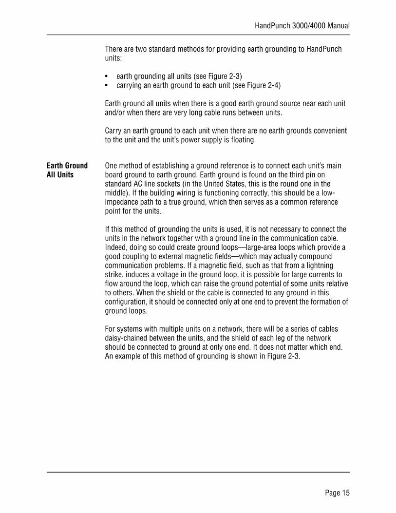
For systems with multiple units on a network, there will be a series of cables daisy-chained between the units, and the shield of each leg of the network should be connected to ground at only one end. It does not matter which end. An example of this method of grounding is shown in Figure 2-3.
Page 15
Planning an Installation
To NextRemote
To NextRemote
t ShieldRemote
Figure 2-3: Communication Shielding With All Units Earth Grounded
All units are connected to the same earth ground. Each shield ground is connected to only one unit, then interrupted to prevent the formation of ground loops. Two sets of lines are wired as shown in Figure 2-3. It does not matter significantly which unit’s GND is used for a particular shield, as long as the path is broken from unit to unit.
Carry a Ground Line to Each Unit
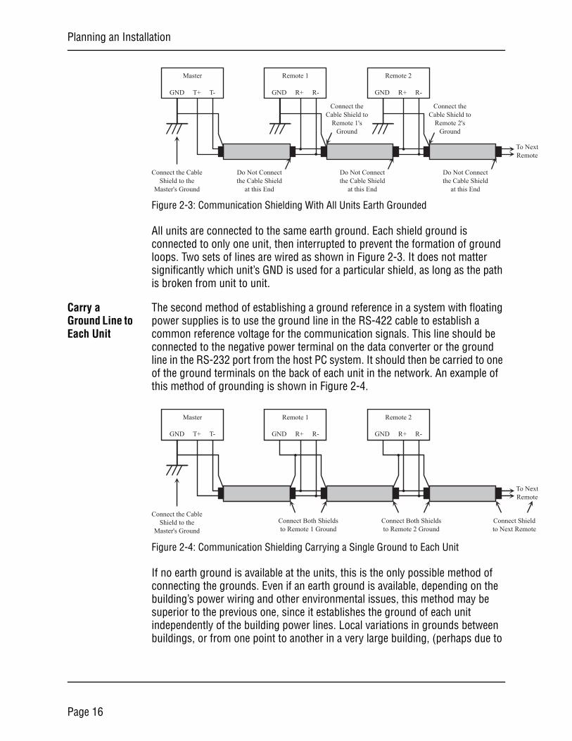
The second method of establishing a ground reference in a system with floating power supplies is to use the ground line in the RS-422 cable to establish a common reference voltage for the communication signals. This line should be connected to the negative power terminal on the data converter or the ground line in the RS-232 port from the host PC system. It should then be carried to one of the ground terminals on the back of each unit in the network. An example of this method of grounding is shown in Figure 2-4.
Figure 2-4: Communication Shielding Carrying a Single Ground to Each Unit
If no earth ground is available at the units, this is the only possible method of connecting the grounds. Even if an earth ground is available, depending on the building’s power wiring and other environmental issues, this method may be superior to the previous one, since it establishes the ground of each unit independently of the building power lines. Local variations in grounds between buildings, or from one point to another in a very large building, (perhaps due to
Master
GND T+ T-
Remote 1
GND R+ R-
Remote 2
GND R+ R-
Connect the CableShield to the
Master's Ground
Do Not Connectthe Cable Shield
at this End
Connect theCable Shield to
Remote 1'sGround
Do Not Connectthe Cable Shield
at this End
Connect theCable Shield to
Remote 2'sGround
Do Not Connectthe Cable Shield
at this End
Master
GND T+ T-
Remote 1
GND R+ R-
Remote 2
GND R+ R-
Connect the CableShield to the
Master's GroundConnect Both Shieldsto Remote 1 Ground
Connect Both Shieldsto Remote 2 Ground
Connecto Next
Page 16
HandPunch 3000/4000 Manual
elevator motors or other large-current drawing machines) will have no effect on the communication network if this configuration is used.
However, the power supplies must be truly floating, with no hidden paths back to the high-voltage side of the transformers, or to earth ground. Since this is difficult to achieve (there is always some parasitic capacitance between the primary and secondary in any transformer), this method may be more susceptible to high-frequency transients in the high-voltage side of the power lines than the earth-grounded method.
The master unit’s ground establishes the ground for the entire system. The main board ground points are connected to the shield ground at each unit, but are not connected to earth ground. The ground point on the master can be the data converter power supply negative terminal, or the GND pin on the RS-232 cable. If the master is an HGU, its main board ground can be used. This configuration should only be used if the power supplies to the units are truly floating, otherwise ground loops will be created, and differences in local grounds may cause large currents to flow through the cable shield.
Page 17
Planning an Installation
Communications
HandPunch to Host Computer Connection
HandPunch/host computer communications can be configured in one of three ways:
• via a direct RS-232 connection• via a direct RS-422 connection using a data converter• via an optional Ethernet network connection (one HandPunch terminal must
have the Ethernet communication option installed)• via an optional Modem connection (one HandPunch terminal must have the
Modem communication option installed)
RS-232 Host Computer Connection
A direct HandPunch connection to a host computer can be made through an 4-conductor cable in an RS-232 serial configuration. A 6’ or 50’ cable may be purchased through RSI or a wiring diagram for the RS-232 to host computer connection is found on Table 4 page 29.
If you make the RS-232 to host computer connection you cannot use the serial printer option (see page 21).
RS-422 Host Computer Connection
A direct HandPunch network connection to a host computer can be made through a shielded, 4-conductor cable in a full-duplex RS-422 configuration. An RJ-11 jack must be installed within 6 feet of the host computer. Position the RJ-11 jack using the template provided in this manual (see Figure 3-2 on page 25). The HandPunch RS-422 network is connected to this jack.
A data converter (Recognition Systems P/N: DC-102) is required to connect the host computer to the RS-422 HandPunch network. The DC-102 is connected to an available RS-232 serial port on the computer. Then connect the DC-102 to the RJ-11 jack using the 8 foot cable provided with the DC-102. A wiring diagram for the RS-422 to host computer connection is found on page 34.
A HandPunch communication network is then connected, unit-to-unit, via an RS-422 “daisy-chain” network. A network RJ-11 jack is installed on or in the wall behind each terminal. Each RJ-11 jack is then interconnected in daisy-chain fashion using two, twisted-pair, AWG22 wires (Recognition Systems recommends using Belden No. 82723 cable). The daisy-chain network can extend up to 4,000 feet in length, and can have up to 31 HandPunch terminals connected to it.
Connect the HandPunch terminal to the RJ-11 jack using the short silver cable provided with the terminal.
NOTE
Page 18
HandPunch 3000/4000 Manual
dh
dh
d
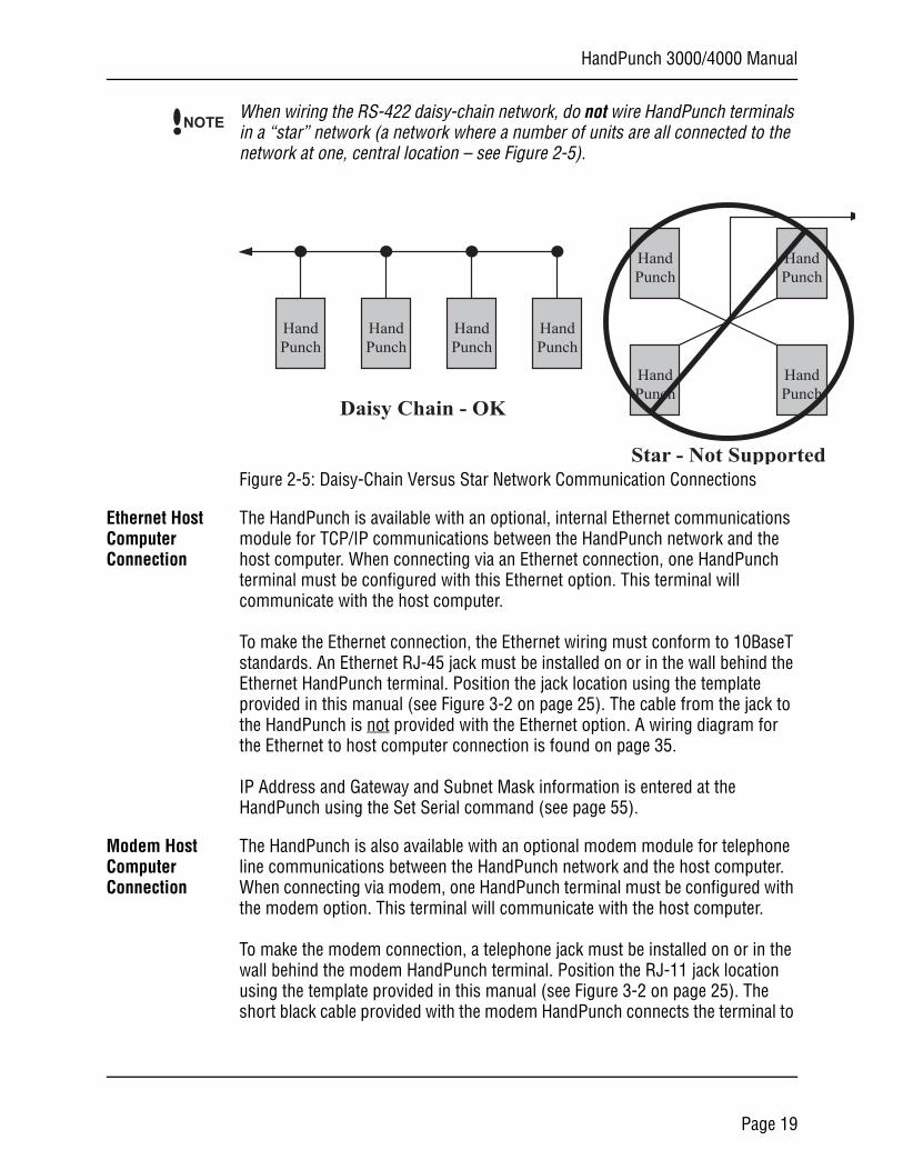
When wiring the RS-422 daisy-chain network, do not wire HandPunch terminals in a “star” network (a network where a number of units are all connected to the network at one, central location – see Figure 2-5).
Figure 2-5: Daisy-Chain Versus Star Network Communication Connections
Ethernet Host Computer Connection
The HandPunch is available with an optional, internal Ethernet communications module for TCP/IP communications between the HandPunch network and the host computer. When connecting via an Ethernet connection, one HandPunch terminal must be configured with this Ethernet option. This terminal will communicate with the host computer.
To make the Ethernet connection, the Ethernet wiring must conform to 10BaseT standards. An Ethernet RJ-45 jack must be installed on or in the wall behind the Ethernet HandPunch terminal. Position the jack location using the template provided in this manual (see Figure 3-2 on page 25). The cable from the jack to the HandPunch is not provided with the Ethernet option. A wiring diagram for the Ethernet to host computer connection is found on page 35.
IP Address and Gateway and Subnet Mask information is entered at the HandPunch using the Set Serial command (see page 55).
Modem Host Computer Connection
The HandPunch is also available with an optional modem module for telephone line communications between the HandPunch network and the host computer. When connecting via modem, one HandPunch terminal must be configured with the modem option. This terminal will communicate with the host computer.
To make the modem connection, a telephone jack must be installed on or in the wall behind the modem HandPunch terminal. Position the RJ-11 jack location using the template provided in this manual (see Figure 3-2 on page 25). The short black cable provided with the modem HandPunch connects the terminal to
NOTE
HandPunch
HandPunch
HandPunch
HandPunch
HandPunch
HanPunc
HandPunch
HanPunc
Daisy Chain - OK
Star - Not Supporte
Page 19
Planning an Installation
the telephone jack. A wiring diagram for a modem to host computer connection is found on page 36.
External DevicesThe HandPunch can control external devices such as:
• Bell• Door Lock• Request to Exit, Door Switch, and Auxiliary Inputs• Auxiliary Outputs• External Card Reader• Serial Printer
The HandPunch requires the use of an external DC power supply to operate other controls or relays. The power supply can be of a different voltage than that used to power the HandPunch. The bell, door lock, and auxiliary outputs switch to ground when activated. For these devices, one pole of a control relay is connected to the PLUS side of the power supply, and the other pole connects to the output connection (switched minus) on the HandPunch. The negative pole on the external power supply must connect to a negative (ground) connection on the HandPunch to complete the circuit. The current draw of the relay or external device must not exceed 0.1A.
Wiring for these devices should enter the HandPunch through the opening in the center of the wall plate or through the conduit opening at the right side of the HandPunch.
The external DC power supplies and relays needed to operate external devices such as bells or door locks are NOT provided by Recognition Systems. You must provide these power supplies.
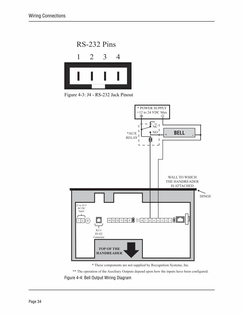
Bell The bell control circuit switches direct current to ground when actuated. The bell must receive its power from an external power supply through the contacts of a bell control relay. Refer to the Bell Output Wiring Diagram on page 30.
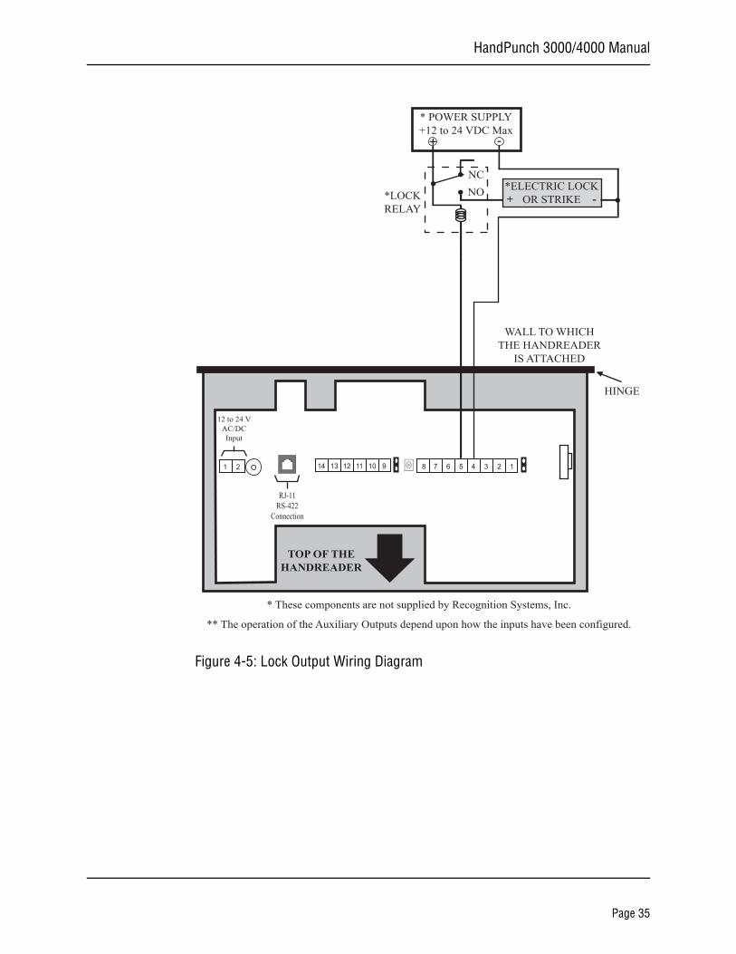
Door Lock The door lock control output of the HandPunch switches to ground upon verification (unless programmed to send card data to a third-party control panel). As the output is limited to 0.1A, a lock control relay must be used. Refer to the Lock Output Wiring Diagram on page 31 for lock output wiring connections. The relay and lock must receive power from an external power supply.
NOTE
Page 20
HandPunch 3000/4000 Manual
Request to Exit, Door Switch, and Auxiliary Inputs
The HandPunch terminal has four inputs. Refer to the Inputs Wiring Diagram on page 32.
• Request to Exit• Door Switch• Two Auxiliary Inputs
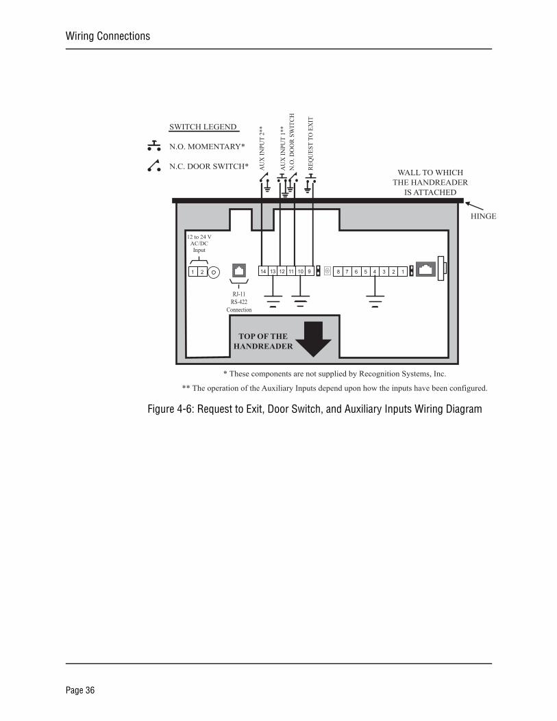
A Request to Exit switch (REX) on the secure side of a controlled door will activate the lock output. When the REX switch is pressed, the door unlocks for a specified time. The REX switch must be a momentary contact, normally open switch rated greater than 0.5 mA, 5 VDC circuit.
A Door Switch monitors door status – open or closed. The door switch must be a normally closed switch rated greater than 0.5 mA, 5 VDC circuit.
Auxiliary Input requirements vary, depending upon the type of input device, but the input device should be rated greater than 0.5 mA, 5 VDC circuit.
Auxiliary Out-puts
The HandPunch allows for the connection of up to three auxiliary output devices. Refer to the Outputs Wiring Diagram on page 32.
External Card Reader
You can connect an external card reader (such as a magnetic stripe, bar code, or proximity reader) to a HandPunch. This external card reader provides a secondary level of user identification.
The HandPunch may require special format programming to be able to read these external card reader formats. Contact your dealer for information.
The connection to an external card reader is made through TS-3 on the HandPunch. Refer to the External Card Reader Wiring Diagram on page 33.
Serial Printer You can connect a serial printer to a HandPunch. A serial printer connected to the HandPunch prints punches as they occur. Recognition Systems does not supply serial printers. The connection to a serial printer is made through J4, the 4 pin connector on the HandPunch. Refer to the Serial Printer Connection Diagram on page 37. Refer to the Printer String Information Application Note (available from Recognition Systems) for detailed information on connecting a serial printer to a HandPunch.
If you use the serial printer option you cannot use the RS-232 HandPunch network to host computer option (see page 17).
NOTE
NOTE
Page 21

Planning an Installation
This page is intentionally blank.
Page 22
HandPunch 3000/4000 Manual
Mechanical InstallationSelect an installation location based on the guidelines provided in the Planning an Installation section beginning on page 11.
Wall Plate Installation
For the following instructions protect the HandPunch from the dust and debris generated during the wall plate installation process.
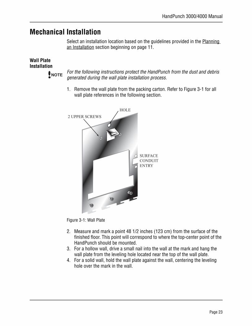
1. Remove the wall plate from the packing carton. Refer to Figure 3-1 for all wall plate references in the following section.
Figure 3-1: Wall Plate
2. Measure and mark a point 48 1/2 inches (123 cm) from the surface of the finished floor. This point will correspond to where the top-center point of the HandPunch should be mounted.
3. For a hollow wall, drive a small nail into the wall at the mark and hang the wall plate from the leveling hole located near the top of the wall plate.
4. For a solid wall, hold the wall plate against the wall, centering the leveling hole over the mark in the wall.
NOTE
2 UPPER SCREWSHOLE
SURFACECONDUITENTRY
Page 23
Mechanical Installation
5. Align a bubble level with the top edge of the wall plate and gently rotate the wall plate until the bubble level shows that the top edge of the wall plate is level.
6. Secure the plate to the wall using heavy masking tape.7. Using the wall plate as a template, mark the locations of the two upper screw
holes and the three lower screw holes.8. For a concealed wiring connection, trace the outline of the open area in the
center of the wall plate. Identify and mark a 1/2 inch hole through which the HandPunch’s wiring will be mounted.
9. For a surface conduit wiring connection, mark the two conduit clamp holes at the right side of the wall plate.
10. Remove the wall plate, masking tape, and the nail (if used).
Mounting the Wall Plate
1. For a hollow wall, use the provided hardware to mount the wall plate. Use the two auger style fasteners for the upper two mounting holes. Use the toggle bolts for the three lower mounting holes.
2. For a solid wall, use expansion bolts to mount the wall plate. For all five mounting holes, drill a 1/4 inch diameter hole, 1/4 of an inch deeper than the length of the expansion anchor.
Routing the Wiring
1. For a concealed wiring connection, drill a 1/2 inch hole in a convenient loca-tion within the open area of the wall plate. Pull the wiring to enter the Hand-Punch through this hole in the open area.
2. For a surface conduit wiring connection, drill a 1/4 inch diameter hole, 1/4 of an inch deeper than the length of the expansion anchor for each of the two conduit clamp holes. Route 1/2 inch conduit to the HandPunch, ending the conduit between the two conduit clamp holes. Pull the wiring to enter the HandPunch through the conduit.
Page 24
HandPunch 3000/4000 Manual
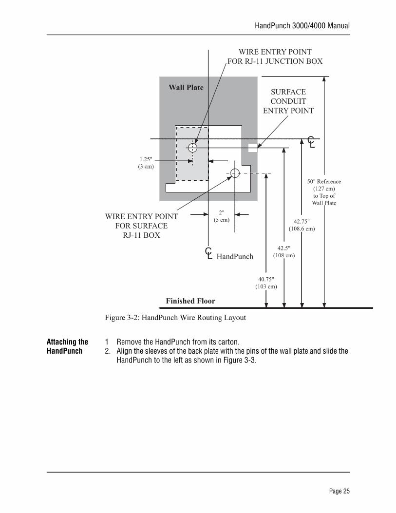
Figure 3-2: HandPunch Wire Routing Layout
Attaching the HandPunch
1 Remove the HandPunch from its carton.2. Align the sleeves of the back plate with the pins of the wall plate and slide the
HandPunch to the left as shown in Figure 3-3.
Wall Plate
Finished Floor
2"(5 cm)
CL HandPunch
WIRE ENTRY POINTFOR SURFACE
RJ-11 BOX
1.25"(3 cm)
WIRE ENTRY POINTFOR RJ-11 JUNCTION BOX
SURFACECONDUIT
ENTRY POINT
CL
40.75"(103 cm)
42.5"(108 cm)
42.75"(108.6 cm)
50" Reference(127 cm)to Top ofWall Plate
Page 25
Mechanical Installation
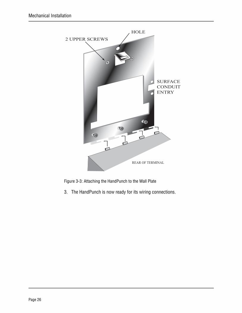
Figure 3-3: Attaching the HandPunch to the Wall Plate
3. The HandPunch is now ready for its wiring connections.
REAR OF TERMINAL
2 UPPER SCREWSHOLE
SURFACECONDUITENTRY
Page 26
HandPunch 3000/4000 Manual
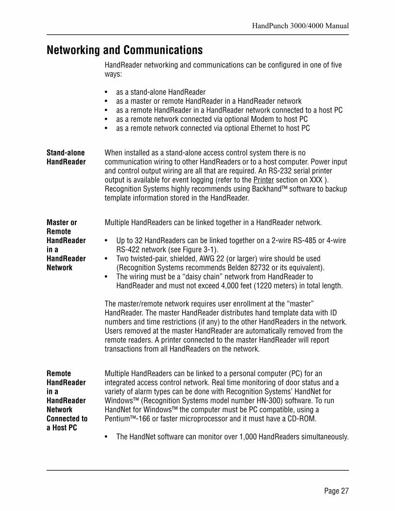
Networking and CommunicationsHandReader networking and communications can be configured in one of five ways:
• as a stand-alone HandReader• as a master or remote HandReader in a HandReader network• as a remote HandReader in a HandReader network connected to a host PC• as a remote network connected via optional Modem to host PC• as a remote network connected via optional Ethernet to host PC
Stand-alone HandReader
When installed as a stand-alone access control system there is no communication wiring to other HandReaders or to a host computer. Power input and control output wiring are all that are required. An RS-232 serial printer output is available for event logging (refer to the Printer section on XXX ). Recognition Systems highly recommends using Backhand™ software to backup template information stored in the HandReader.
Master or Remote HandReader in a HandReader Network
Multiple HandReaders can be linked together in a HandReader network.
• Up to 32 HandReaders can be linked together on a 2-wire RS-485 or 4-wire RS-422 network (see Figure 3-1).
• Two twisted-pair, shielded, AWG 22 (or larger) wire should be used (Recognition Systems recommends Belden 82732 or its equivalent).
• The wiring must be a “daisy chain” network from HandReader to HandReader and must not exceed 4,000 feet (1220 meters) in total length.
The master/remote network requires user enrollment at the “master” HandReader. The master HandReader distributes hand template data with ID numbers and time restrictions (if any) to the other HandReaders in the network. Users removed at the master HandReader are automatically removed from the remote readers. A printer connected to the master HandReader will report transactions from all HandReaders on the network.
Remote HandReader in a HandReader Network Connected to a Host PC
Multiple HandReaders can be linked to a personal computer (PC) for an integrated access control network. Real time monitoring of door status and a variety of alarm types can be done with Recognition Systems’ HandNet for Windows™ (Recognition Systems model number HN-300) software. To run HandNet for Windows™ the computer must be PC compatible, using a Pentium™-166 or faster microprocessor and it must have a CD-ROM.
• The HandNet software can monitor over 1,000 HandReaders simultaneously.
Page 27
Networking and Communications
• An unlimited number of sites can be created with up to 32 HandReaders per site.
• The HandReaders report all transactions to the PC. The HandNet software records all transactions and displays a variety of reports generated from this information.
• Template management is handled automatically.• Users may enroll at any HandReader in the system. The PC collects the data
and distributes it to other HandReaders in the network.• Access may be restricted by time and by HandReader via HandNet’s access
profiles and by the use of time zones.
Typically, HandReader networks link to a PC using an RS-422 connection. These networks have the following requirements.
• Two twisted pair, shielded, AWG 22 wire or larger should be used (Recognition Systems recommends Belden No. 82723 or equivalent cable).
• HandReaders must be wired together in a “daisy chain” network from HandReader to HandReader and then to the host PC. The total length of the wiring must not exceed 4,000 feet per network.
• The network requires an RS-422 to RS-232 converter (Recognition Systems P/N DC-102) at the PC.
Recognition Systems’ optional HandNet for Windows™ software allows programming of most of the remote HandReader setups from the computer. However, each HandReader on the network requires the setting of an address. HandReader addresses may be repeated, but only on different sites. Display language, date format changes, and the communication mode must also be set at the HandReader.
Remote HandReader Connected to a Host PC via Optional Modem
An optional, internal “answer only” 14.4 bps modem is available for HandReaders. This modem is designed for operation with United States phone systems. Site wiring should conform to standard telephone wiring standards and terminate at the HandReader with a standard RJ-11 modular phone jack. Each HandReader with a modem includes a XXXX cable for the final connection between the phone jack and the HandReader modem. Modem HandReaders may be networked with up to 31 non-modem HandReaders using RS-422 wiring. Refer to the Modem Application Note (available from Recognition Systems) for detailed information.
Page 28
HandPunch 3000/4000 Manual
Remote HandReader Connected to a Host PC via Optional Ethernet
The HandReader is available with an optional, internal Ethernet communications module for TCP/IP communications. The wiring must conform to 10BaseT standards. Typically, network wiring terminates at the HandReader with a standard RJ-45 modular jack. The cable from the jack to the HandReader is not provided with the Ethernet option. The IP address, Gateway, and Host Bits are entered at the HandReader in the SET SERIAL menu. Ethernet HandReaders may be networked with up to 31 non-Ethernet HandReaders using RS-422 twisted pair cable. Refer to the Ethernet Application Note (available from Recognition Systems) for detailed information.
Printer A serial printer can be connected to a HandReader. A printer connected to a remote HandReader will print only the events that occur at that HandReader. Recognition Systems Inc. does not supply serial printers. Refer to the Printer String Application Note (available from Recognition Systems) for detailed information.
Page 29

Networking and Communications
This page is intentionally blank.
Page 30
HandPunch 3000/4000 Manual
l
Wiring Connections
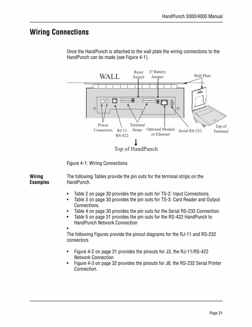
Once the HandPunch is attached to the wall plate the wiring connections to the HandPunch can be made (see Figure 4-1).
Figure 4-1: Wiring Connections
Wiring Examples
The following Tables provide the pin outs for the terminal strips on the HandPunch.
• Table 2 on page 30 provides the pin outs for TS-2: Input Connections.• Table 3 on page 30 provides the pin outs for TS-3: Card Reader and Output
Connections.• Table 4 on page 30 provides the pin outs for the Serial RS-232 Connection.• Table 5 on page 31 provides the pin outs for the RS-422 HandPunch to
HandPunch Network Connection•The following Figures provide the pinout diagrams for the RJ-11 and RS-232 connectors
• Figure 4-2 on page 31 provides the pinouts for J3, the RJ-11/RS-422 Network Connection
• Figure 4-3 on page 32 provides the pinouts for J8, the RS-232 Serial Printer Connection.
WALL
Serial RS-232Optional Modemor Ethernet
Wall Plate
Top ofTermina
Top of HandPunch
PowerConnectors
J7 BatteryJumper
TerminalStrips
ResetSwitch
RJ-11RS-422
Page 31
Wiring Connections
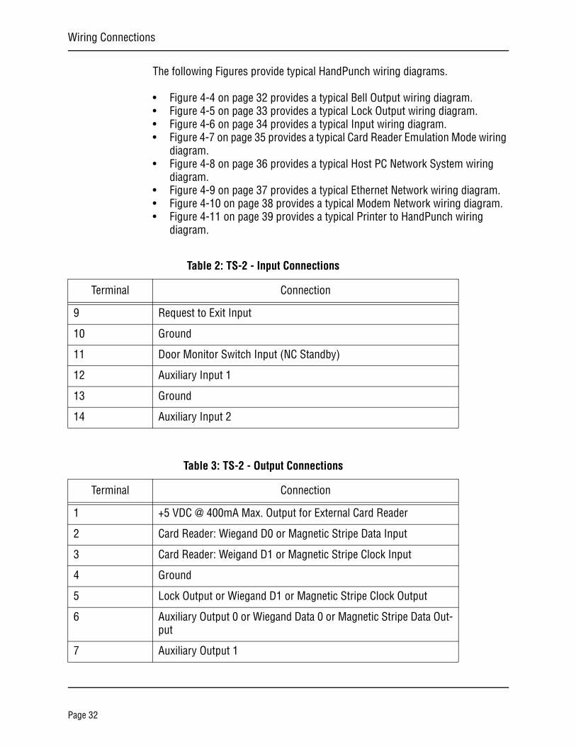
The following Figures provide typical HandPunch wiring diagrams.
• Figure 4-4 on page 32 provides a typical Bell Output wiring diagram.• Figure 4-5 on page 33 provides a typical Lock Output wiring diagram.• Figure 4-6 on page 34 provides a typical Input wiring diagram.• Figure 4-7 on page 35 provides a typical Card Reader Emulation Mode wiring
diagram.• Figure 4-8 on page 36 provides a typical Host PC Network System wiring
diagram.• Figure 4-9 on page 37 provides a typical Ethernet Network wiring diagram.• Figure 4-10 on page 38 provides a typical Modem Network wiring diagram.• Figure 4-11 on page 39 provides a typical Printer to HandPunch wiring
diagram.
Table 2: TS-2 - Input Connections
Terminal Connection
9 Request to Exit Input
10 Ground
11 Door Monitor Switch Input (NC Standby)
12 Auxiliary Input 1
13 Ground
14 Auxiliary Input 2
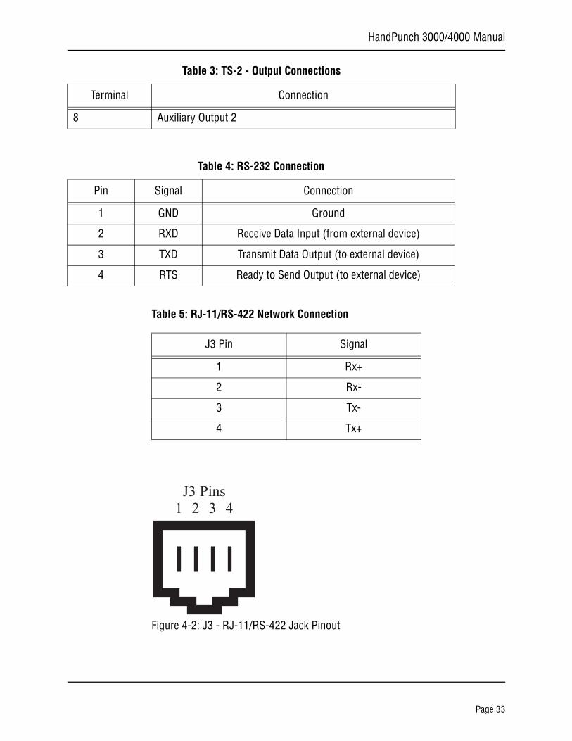
Table 3: TS-2 - Output Connections
Terminal Connection
1 +5 VDC @ 400mA Max. Output for External Card Reader
2 Card Reader: Wiegand D0 or Magnetic Stripe Data Input
3 Card Reader: Weigand D1 or Magnetic Stripe Clock Input
4 Ground
5 Lock Output or Wiegand D1 or Magnetic Stripe Clock Output
6 Auxiliary Output 0 or Wiegand Data 0 or Magnetic Stripe Data Out-put
7 Auxiliary Output 1
Page 32
HandPunch 3000/4000 Manual
Table 5: RJ-11/RS-422 Network Connection
Figure 4-2: J3 - RJ-11/RS-422 Jack Pinout
8 Auxiliary Output 2
Table 3: TS-2 - Output Connections
Terminal Connection
Table 4: RS-232 Connection
Pin Signal Connection
1 GND Ground
2 RXD Receive Data Input (from external device)
3 TXD Transmit Data Output (to external device)
4 RTS Ready to Send Output (to external device)
J3 Pin Signal
1 Rx+
2 Rx-
3 Tx-
4 Tx+
J3 Pins1 2 3 4
Page 33
Wiring Connections
Figure 4-3: J4 - RS-232 Jack Pinout
Figure 4-4: Bell Output Wiring Diagram
1 2 3 4
RS-232 Pins
* These components are not supplied by Recognition Systems, Inc.
TOP OF THEHANDREADER
HINGE
WALL TO WHICHTHE HANDREADER
IS ATTACHED
** The operation of the Auxiliary Outputs depend upon how the inputs have been configured.
12 to 24 VAC/DCInput
14 13 12 11 10 9 8 7 6 5 4 3 2 1 1 2
+ -
* POWER SUPPLY+12 to 24 VDC Max
NCNO*AUX
RELAYBELL+ -
RJ-11RS-422
Connection
Page 34
HandPunch 3000/4000 Manual
Figure 4-5: Lock Output Wiring Diagram
* These components are not supplied by Recognition Systems, Inc.
TOP OF THEHANDREADER
HINGE
WALL TO WHICHTHE HANDREADER
IS ATTACHED
+ -
* POWER SUPPLY+12 to 24 VDC Max
NCNO*LOCK
RELAY
*ELECTRIC LOCKOR STRIKE+ -
** The operation of the Auxiliary Outputs depend upon how the inputs have been configured.
12 to 24 VAC/DCInput
14 13 12 11 10 9 8 7 6 5 4 3 2 1 1 2
RJ-11RS-422
Connection
Page 35
Wiring Connections
Figure 4-6: Request to Exit, Door Switch, and Auxiliary Inputs Wiring Diagram
* These components are not supplied by Recognition Systems, Inc.
TOP OF THEHANDREADER
HINGE
WALL TO WHICHTHE HANDREADER
IS ATTACHED
SWITCH LEGEND
N.O. MOMENTARY*
N.C. DOOR SWITCH*
** The operation of the Auxiliary Inputs depend upon how the inputs have been configured.
12 to 24 VAC/DCInput
14 13 12 11 10 9 8 7 6 5 4 3 2 1 1 2
REQ
UES
T TO
EX
IT
N.O
. DO
OR
SWIT
CH
AU
X IN
PUT
2**
AU
X IN
PUT
1**
RJ-11RS-422
Connection
Page 36
HandPunch 3000/4000 Manual
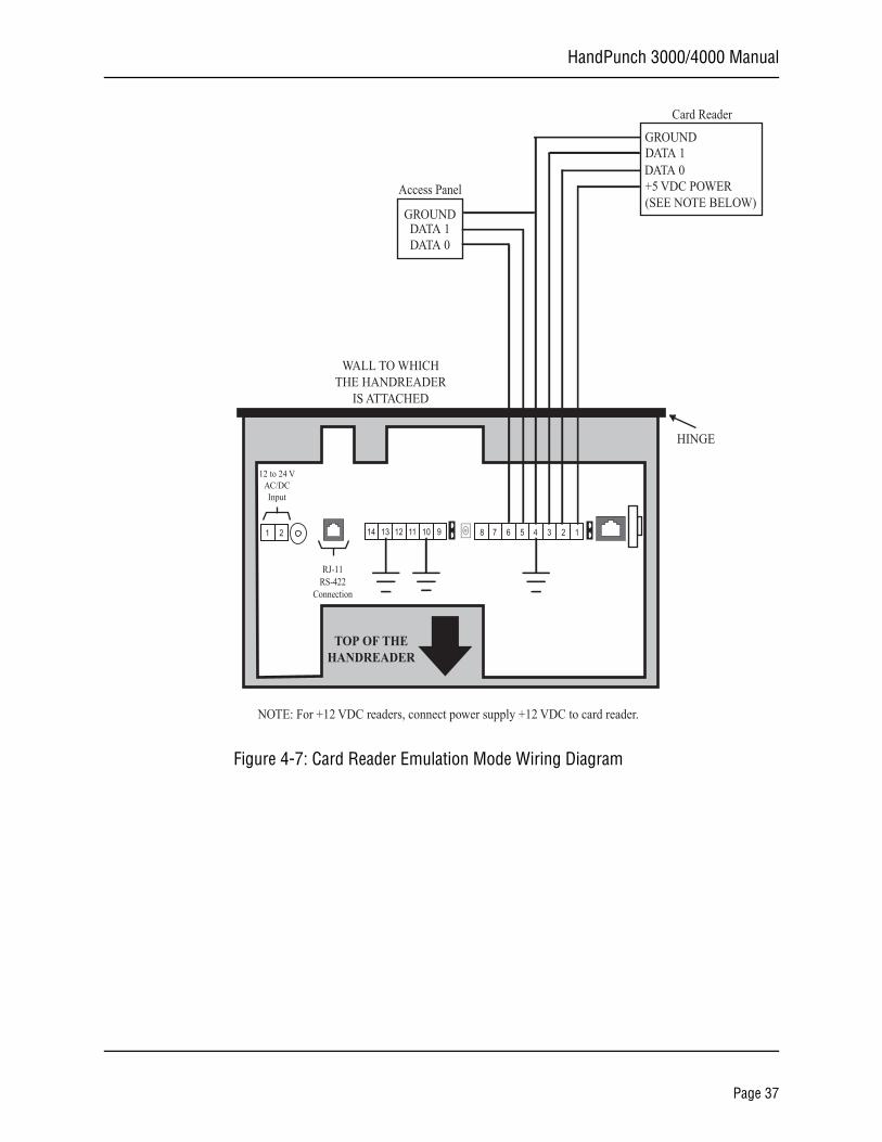
Figure 4-7: Card Reader Emulation Mode Wiring Diagram
TOP OF THEHANDREADER
HINGE
WALL TO WHICHTHE HANDREADER
IS ATTACHED
12 to 24 VAC/DCInput
14 13 12 11 10 9 8 7 6 5 4 3 2 1 1 2
GROUNDDATA 1
GROUNDDATA 1DATA 0
DATA 0+5 VDC POWER(SEE NOTE BELOW)
Access Panel
Card Reader
NOTE: For +12 VDC readers, connect power supply +12 VDC to card reader.
RJ-11RS-422
Connection
Page 37
Wiring Connections
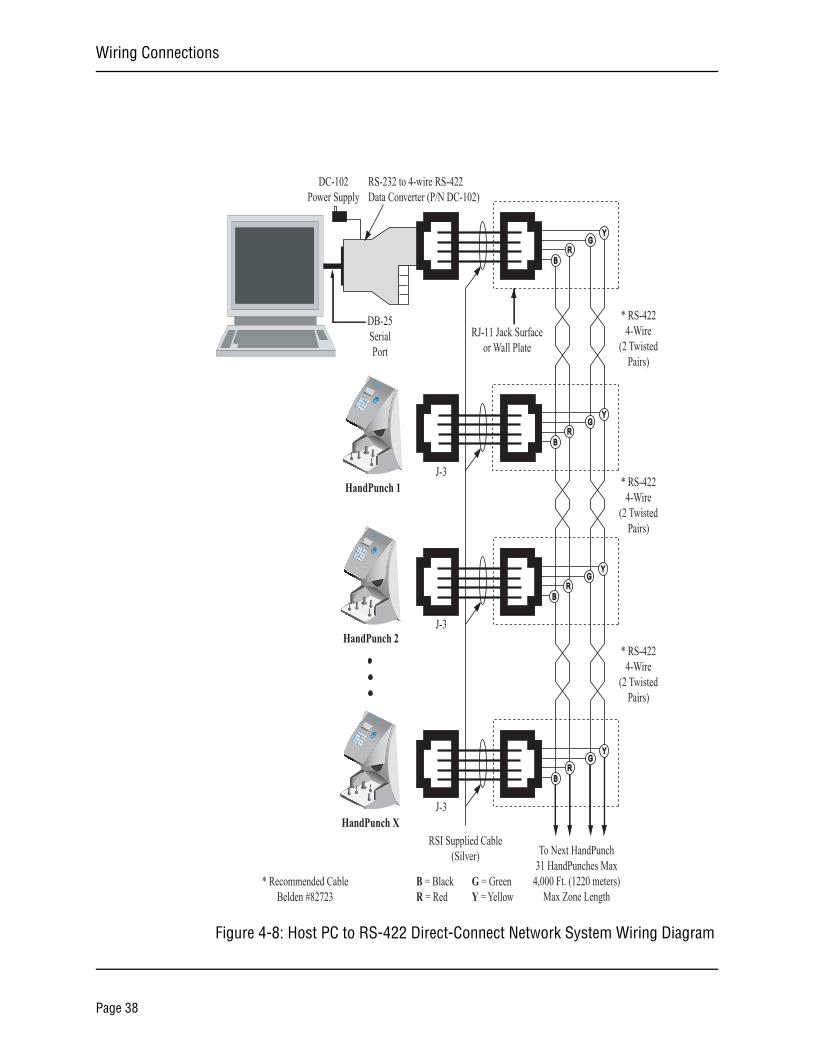
Figure 4-8: Host PC to RS-422 Direct-Connect Network System Wiring Diagram
54
6F18
7
9F20
NoEnter
21
3Clear
*
#Yes
No
Recognition Systems Inc.
HandPunch 1
54
6F18
7
9F20
NoEnter
21
3Clear
*
#Yes
No
Recognition Systems Inc.
HandPunch 2
54
6F18
7
9F20
NoEnter
21
3Clear
*
#Yes
No
Recognition Systems Inc.
HandPunch X
DB-25SerialPort
DC-102Power Supply
RS-232 to 4-wire RS-422Data Converter (P/N DC-102)
RSI Supplied Cable(Silver)
RJ-11 Jack Surfaceor Wall Plate
* RS-4224-Wire
(2 TwistedPairs)
RG
Y
B
RG
Y
B
RG
Y
B
BR
GY
To Next HandPunch31 HandPunches Max
4,000 Ft. (1220 meters)Max Zone Length
* Recommended CableBelden #82723
* RS-4224-Wire
(2 TwistedPairs)
* RS-4224-Wire
(2 TwistedPairs)
B = BlackR = Red
G = GreenY = Yellow
J-3
J-3
J-3
Page 38
HandPunch 3000/4000 Manual
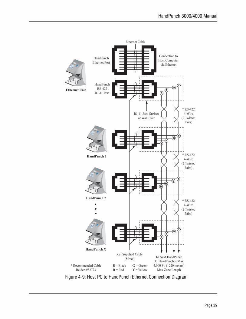
Figure 4-9: Host PC to HandPunch Ethernet Connection Diagram
54
6F18
7
9F20
NoEnter
21
3Clear
*
#Yes
No
Recognition Systems Inc.
HandPunch 1
54
6F18
7
9F20
NoEnter
21
3Clear
*
#Yes
No
Recognition Systems Inc.
HandPunch 2
54
6F18
7
9F20
NoEnter
21
3Clear
*
#Yes
No
Recognition Systems Inc.
HandPunch XRSI Supplied Cable
(Silver)
RJ-11 Jack Surfaceor Wall Plate
RG
Y
B
RG
Y
B
RG
Y
B
BR
GY
To Next HandPunch31 HandPunches Max
4,000 Ft. (1220 meters)Max Zone Length
* Recommended CableBelden #82723
54
6F18
7
9F20
NoEnter
21
3Clear
*
#Yes
No
Recognition Systems Inc.
Ethernet UnitHandPunch
RS-422RJ-11 Port
HandPunchEthernet Port
Ethernet Cable
Connection toHost Computer
via Ethernet
* RS-4224-Wire
(2 TwistedPairs)
* RS-4224-Wire
(2 TwistedPairs)
* RS-4224-Wire
(2 TwistedPairs)
B = BlackR = Red
G = GreenY = Yellow
Page 39
Wiring Connections
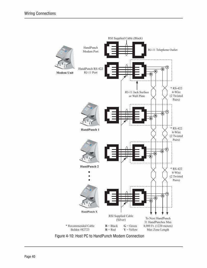
Figure 4-10: Host PC to HandPunch Modem Connection
54
6F18
7
9F20
NoEnter
21
3Clear
*
#Yes
No
Recognition Systems Inc.
HandPunch 1
54
6F18
7
9F20
NoEnter
21
3Clear
*
#Yes
No
Recognition Systems Inc.
HandPunch 2
54
6F18
7
9F20
NoEnter
21
3Clear
*
#Yes
No
Recognition Systems Inc.
HandPunch X
RSI Supplied Cable(Silver)
RJ-11 Jack Surfaceor Wall Plate
RG
Y
B
RG
Y
B
RG
Y
B
BR
GY
To Next HandPunch31 HandPunches Max
4,000 Ft. (1220 meters)Max Zone Length
* Recommended CableBelden #82723
54
6F18
7
9F20
NoEnter
21
3Clear
*
#Yes
No
Recognition Systems Inc.
Modem UnitHandPunch RS-422
RJ-11 Port
HandPunchModem Port
RSI Supplied Cable (Black)
RJ-11 Telephone Outlet
* RS-4224-Wire
(2 TwistedPairs)
* RS-4224-Wire
(2 TwistedPairs)
* RS-4224-Wire
(2 TwistedPairs)
B = BlackR = Red
G = GreenY = Yellow
Page 40
HandPunch 3000/4000 Manual
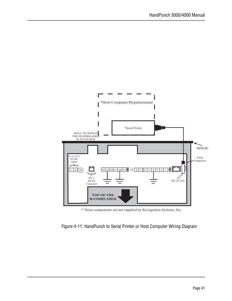
Figure 4-11: HandPunch to Serial Printer or Host Computer Wiring Diagram
* These components are not supplied by Recognition Systems, Inc.
HINGE
WALL TO WHICHTHE HANDREADER
IS ATTACHED
TOP OF THEHANDREADER
HINGE
12 to 24 VAC/DCInput
14 13 12 11 10 9 8 7 6 5 4 3 2 1 1 2
*Serial Printer
4 PinConnector
J4RS-232 Jack
RJ-11RS-422
Connection
*Host Computer/Hyperterminal
Page 41

Wiring Connections
This page is intentionally blank.
Page 42
HandPunch 3000/4000 Manual
Erasing the Memory
There are two options when erasing the memory of the HandReader.
1. Setup2. All
The erasing of the setup will set the HandReader’s address, passwords, etc back to factory defaults.
Choosing the All option will take the HandReader’s setup back to factory defaults plus earse all user databases and datalogs. This action can not be undone. If there is a software that is managing the system then the users can be downloaded back to the HandReader if needed.
Erasing HandReader Memory
The erase memory function allows a HandReader’s setup and/or user database to be erased.Perform the following steps to erase the setup programs but retain the user database.
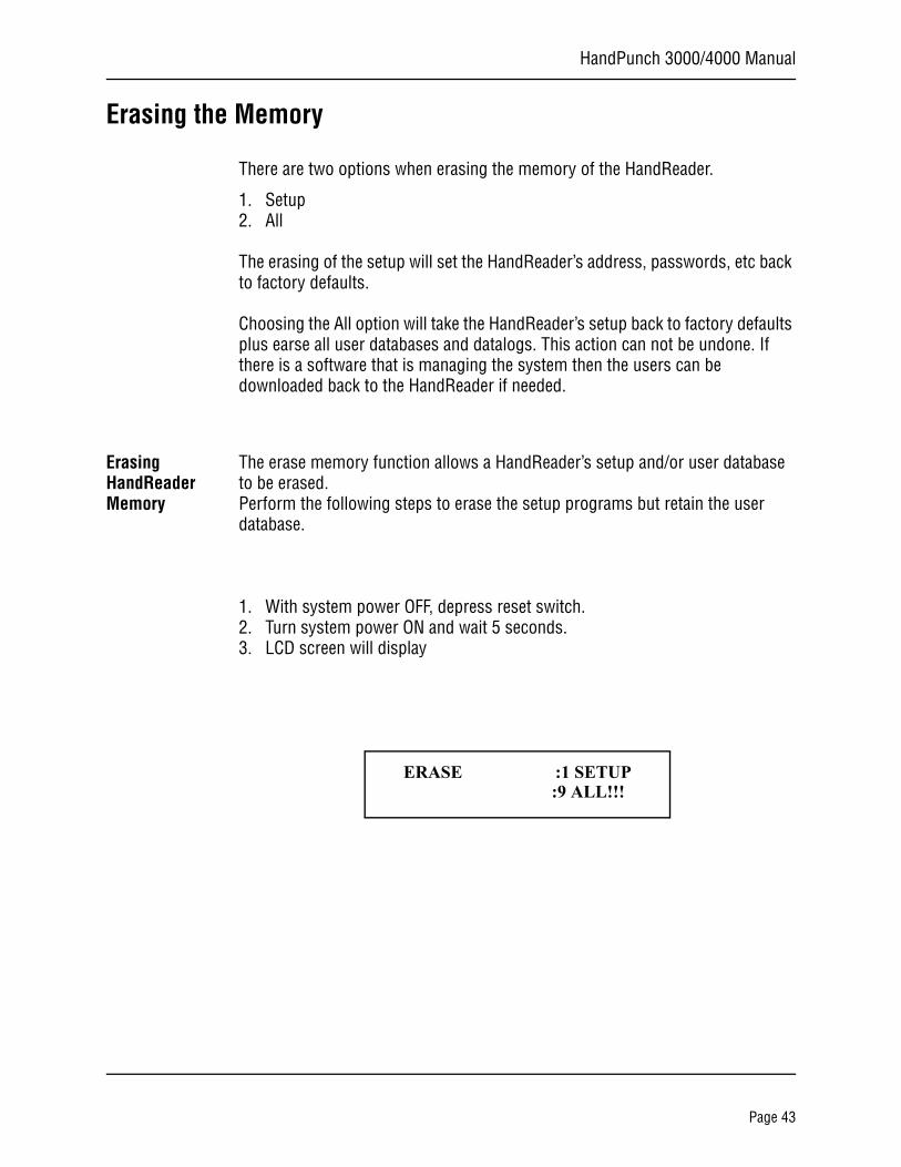
1. With system power OFF, depress reset switch.2. Turn system power ON and wait 5 seconds.3. LCD screen will display
ERASE :1 SETUP :9 ALL!!!
Page 43

Ereasing Memory
This page is intentionally blank.
Page 44
HandPunch 3000/4000 Manual
Closing the HandPunch
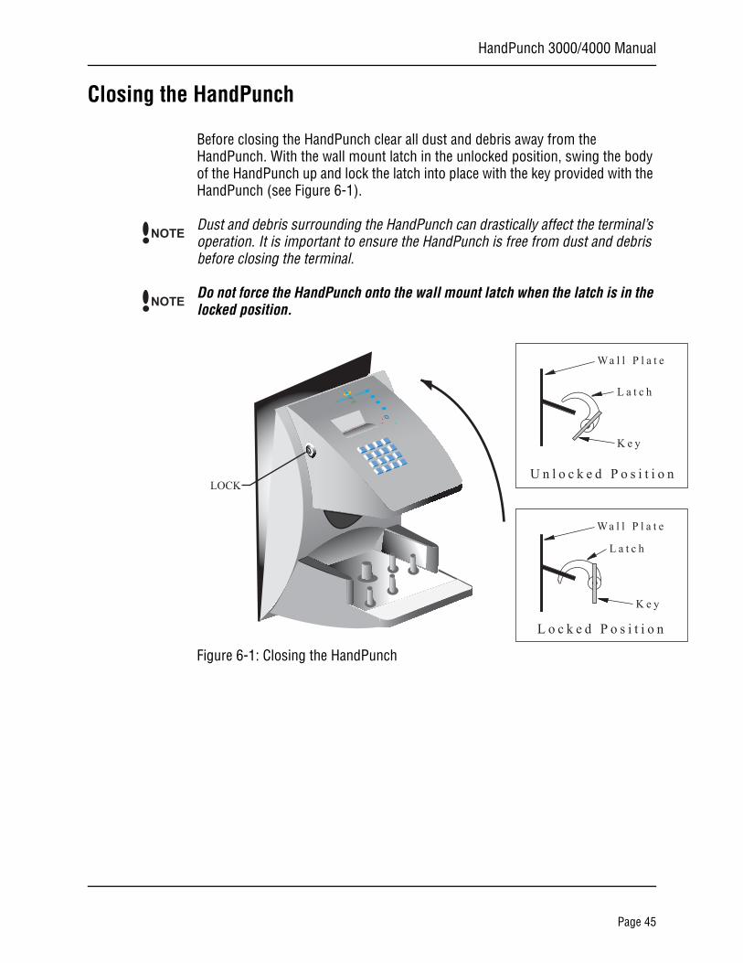
Before closing the HandPunch clear all dust and debris away from the HandPunch. With the wall mount latch in the unlocked position, swing the body of the HandPunch up and lock the latch into place with the key provided with the HandPunch (see Figure 6-1).
Dust and debris surrounding the HandPunch can drastically affect the terminal’s operation. It is important to ensure the HandPunch is free from dust and debris before closing the terminal.
Do not force the HandPunch onto the wall mount latch when the latch is in the locked position.
Figure 6-1: Closing the HandPunch
NOTE
NOTE
No
Recognition Systems Inc.
LOCK
K e y
L a t c h
Wa l l P l a t e
K e y
L a t c h
Wa l l P l a t e
U n l o c k e d P o s i t i o n
L o c k e d P o s i t i o n
Page 45

Closing the HandPunch
This page is intentionally blank.
Page 46
HandPunch 3000/4000 Manual
Enter Command Menu
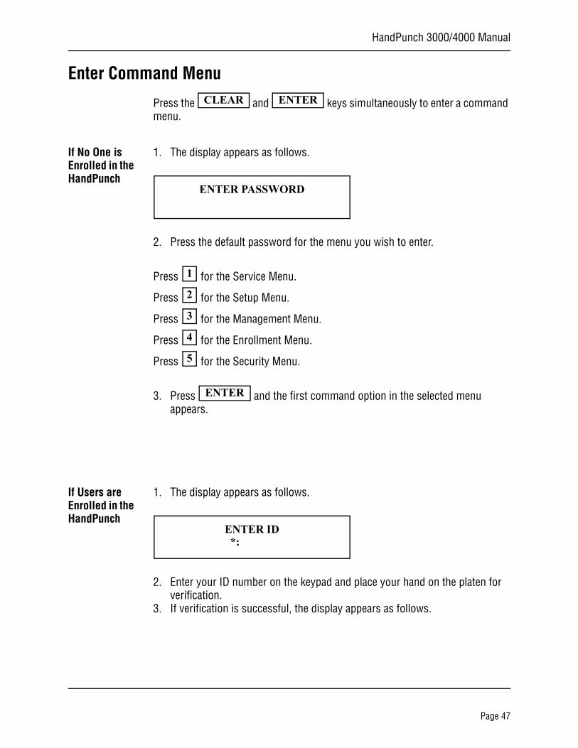
Press the and keys simultaneously to enter a command menu.
If No One is Enrolled in the HandPunch
1. The display appears as follows.
2. Press the default password for the menu you wish to enter.
Press for the Service Menu.
Press for the Setup Menu.
Press for the Management Menu.
Press for the Enrollment Menu.
Press for the Security Menu.
3. Press and the first command option in the selected menu appears.
If Users are Enrolled in the HandPunch
1. The display appears as follows.
2. Enter your ID number on the keypad and place your hand on the platen for verification.
3. If verification is successful, the display appears as follows.
CLEAR ENTER
ENTER PASSWORD
1
2
3
4
5
ENTER
ENTER ID*:
Page 47
Enter a Command Menu
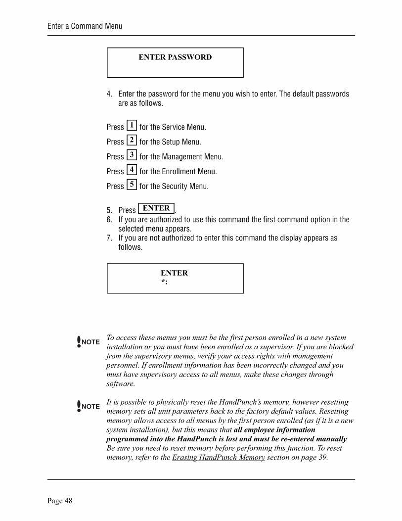
4. Enter the password for the menu you wish to enter. The default passwords are as follows.
Press for the Service Menu.
Press for the Setup Menu.
Press for the Management Menu.
Press for the Enrollment Menu.
Press for the Security Menu.
5. Press .6. If you are authorized to use this command the first command option in the
selected menu appears.7. If you are not authorized to enter this command the display appears as
follows.
To access these menus you must be the first person enrolled in a new system installation or you must have been enrolled as a supervisor. If you are blocked from the supervisory menus, verify your access rights with management personnel. If enrollment information has been incorrectly changed and you must have supervisory access to all menus, make these changes through software.
It is possible to physically reset the HandPunch’s memory, however resetting memory sets all unit parameters back to the factory default values. Resetting memory allows access to all menus by the first person enrolled (as if it is a new system installation), but this means that all employee information programmed into the HandPunch is lost and must be re-entered manually. Be sure you need to reset memory before performing this function. To reset memory, refer to the Erasing HandPunch Memory section on page 39.
ENTER PASSWORD
1
2
3
4
5
ENTER
ENTER *:
NOTE
NOTE
Page 48
HandPunch 3000/4000 Manual
Navigating Command Menus
Once you have entered a command menu, there are three options available for navigating the command menu system.
• Press to enter the command shown on the display.
• Press to step to the next command in the menu.
• Press to exit the command menu (pressing any numeric key also exits the command menu). If you are in a command’s sub-menu, you
may have to press multiple times to completely exit the command menu.
#
*
CLEAR
CLEAR
Page 49

Enter a Command Menu
This page is intentionally blank.
Page 50
HandPunch 3000/4000 Manual
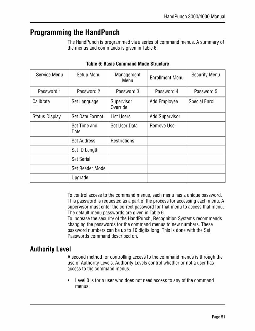
Programming the HandPunchThe HandPunch is programmed via a series of command menus. A summary of the menus and commands is given in Table 6.
To control access to the command menus, each menu has a unique password. This password is requested as a part of the process for accessing each menu. A supervisor must enter the correct password for that menu to access that menu. The default menu passwords are given in Table 6.To increase the security of the HandPunch, Recognition Systems recommends changing the passwords for the command menus to new numbers. These password numbers can be up to 10 digits long. This is done with the Set Passwords command described on.
Authority LevelA second method for controlling access to the command menus is through the use of Authority Levels. Authority Levels control whether or not a user has access to the command menus.
• Level 0 is for a user who does not need access to any of the command menus.
Table 6: Basic Command Mode Structure
Service Menu Setup Menu Management Menu Enrollment Menu Security Menu
Password 1 Password 2 Password 3 Password 4 Password 5
Calibrate Set Language Supervisor Override
Add Employee Special Enroll
Status Display Set Date Format List Users Add Supervisor
Set Time and Date
Set User Data Remove User
Set Address Restrictions
Set ID Length
Set Serial
Set Reader Mode
Upgrade
Page 51
Programming the HandPunch
• Level 5 is assigned to Supervisors who need access to all of the command menus.
The HandPunch automatically assigns Authority Level 0 to users enrolled by the Add Employee command. Authority Level 5 is automatically assigned to users enrolled by the Add Supervisor command.
Until a user has been assigned to Supervisor, every user can access every menu. Once a user has been enrolled using the Add Supervisor (designated as a supervisor), all further user authority levels are assigned. The first person enrolled should be enrolled using the Add Supervisor command. This protects the integrity of the system. Recognition Systems strongly recommends enrolling at least two users as supervisors to ensure that more than one person has the authority to access all menus and all commands.
Programming OrderWhen setting up HandPunch operations there is a general programming/operations order that should be followed.
Set HandPunch Site Parameters – Set the HandPunch site parameters to meet site-specific needs and usage: change the language used by the display, set the HandPunch’s address, and set the serial communication baud rate (used if you have installed a serial printer – see page 51).
Enroll Supervisory Staff – Enroll yourself and the supervisors who will have responsibility for HandPunch management. This is done through the Enrollment Menu (see Supervisor Enrollment on page 62).
The time, date, and ID number length are normally set by the host computer. However, a supervisor can change these parameters at a HandPunch after setup information has been downloaded from the host computer.
These tasks are done through the Setup Menu. The instructions for reader setup parameters begin on page 51.
Train and Enroll Users – Train each user regarding HandPunch usage and then Enroll each user. This is done through the Enrollment Menu. The instructions for employee enrollment begin on page 61. Special enrollment allows you to enroll people with disabilities that prevent them from using the HandPunch properly. Employees with special enrollment ID numbers can punch in without biometric verification.
This means that anyone who knows a special enrollment ID number can punch in. This function should only be used if absolutely necessary. The instructions for special enrollment begin on page 63.
NOTE
NOTE
WARNING
Page 52
HandPunch 3000/4000 Manual
System ManagementOnce a HandPunch system is in operation the following commands are used for system management.
Supervisor Override – Review employee punch history, add bulk hours or dollars, or record a punch for an employee. This is done through the Management Menu. The instructions for supervisor override begin on page 57.
List Users – List the Users authorized to use a HandPunch. This is done through the Management Menu. The instructions for listing employees begin on page 58.
Set User Data – Set a user’s reject threshold (adjusting the sensitivity applied when a HandPunch reads a hand) and assign time zones to users (defining when users are allowed to punch in and out). These tasks are done through the Management Menu. The instructions for setting user data begin on page 58.
Restrictions – Set or remove time restrictions for when employees punch in. This is done through the Management Menu. The instructions for setting time restrictions begin on page 58.
Remove User – Remove employees (and supervisors) from a HandPunch. This is done through the Enrollment Menu. The instructions for removing employees begin on page 62.
Set Amnesty1 – Temporarily remove time restrictions at a HandPunch to accommodate circumstances that may affect when employees punch in (such as inclement weather). This is done through the Management Menu. The instructions for setting amnesty begin on page 58.
1. On HandPunch 4000 units only.
Page 53
Programming the HandPunch
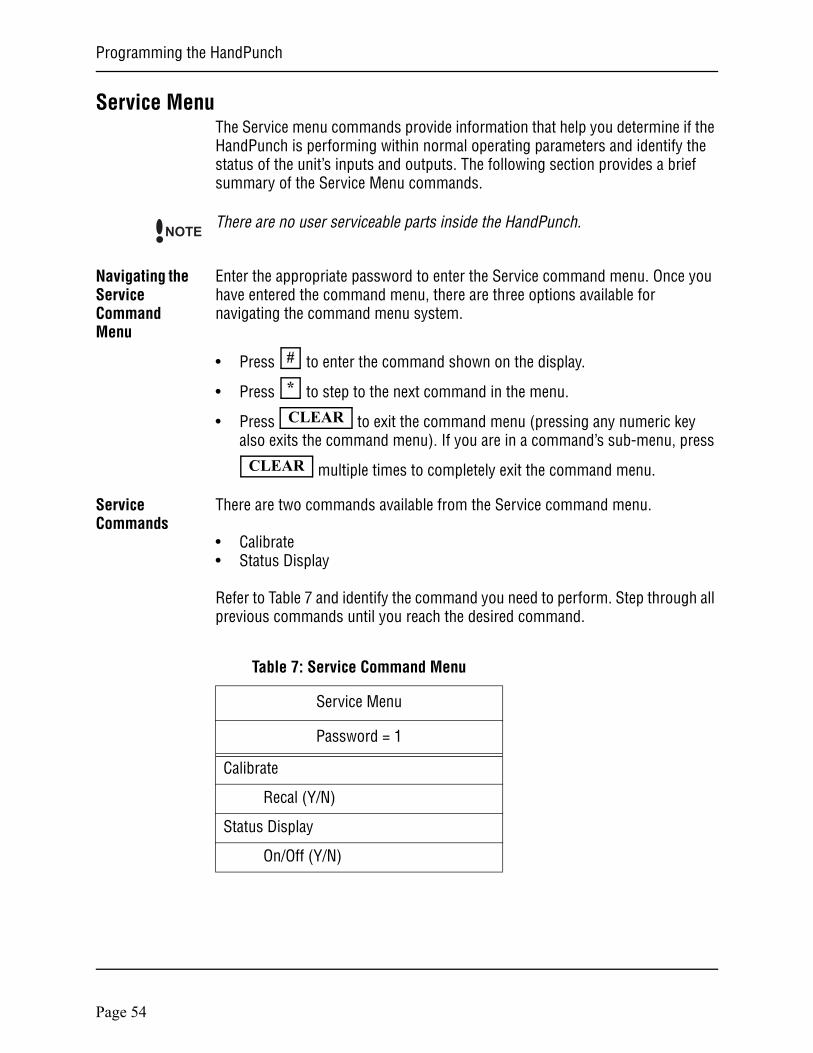
Service MenuThe Service menu commands provide information that help you determine if the HandPunch is performing within normal operating parameters and identify the status of the unit’s inputs and outputs. The following section provides a brief summary of the Service Menu commands.
There are no user serviceable parts inside the HandPunch.
Navigating the Service Command Menu
Enter the appropriate password to enter the Service command menu. Once you have entered the command menu, there are three options available for navigating the command menu system.
• Press to enter the command shown on the display.
• Press to step to the next command in the menu.
• Press to exit the command menu (pressing any numeric key also exits the command menu). If you are in a command’s sub-menu, press
multiple times to completely exit the command menu.
Service Commands
There are two commands available from the Service command menu.
• Calibrate• Status Display
Refer to Table 7 and identify the command you need to perform. Step through all previous commands until you reach the desired command.
NOTE
#
*
CLEAR
CLEAR
Table 7: Service Command Menu
Service Menu
Password = 1
Calibrate
Recal (Y/N)
Status Display
On/Off (Y/N)
Page 54
HandPunch 3000/4000 Manual
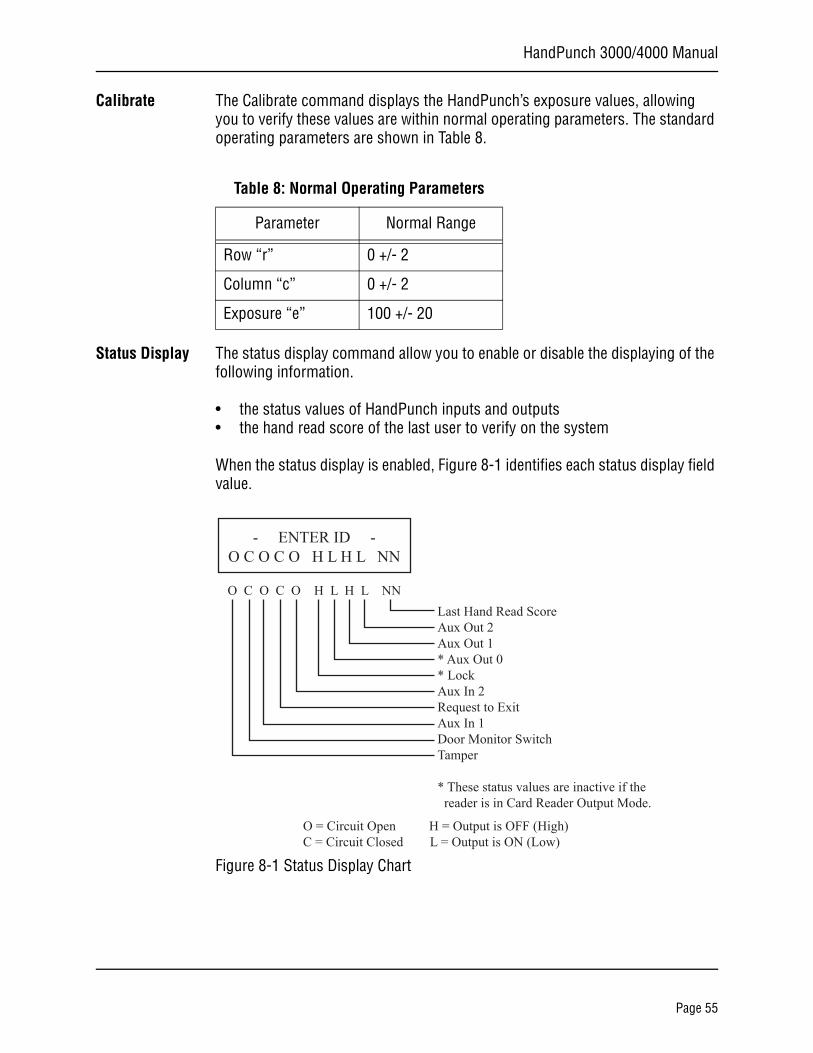
Calibrate The Calibrate command displays the HandPunch’s exposure values, allowing you to verify these values are within normal operating parameters. The standard operating parameters are shown in Table 8.
Status Display The status display command allow you to enable or disable the displaying of the following information.
• the status values of HandPunch inputs and outputs• the hand read score of the last user to verify on the system
When the status display is enabled, Figure 8-1 identifies each status display field value.
Figure 8-1 Status Display Chart
Table 8: Normal Operating Parameters
Parameter Normal Range
Row “r” 0 +/- 2
Column “c” 0 +/- 2
Exposure “e” 100 +/- 20
Last Hand Read ScoreAux Out 2Aux Out 1* Aux Out 0* LockAux In 2Request to ExitAux In 1Door Monitor SwitchTamper
* These status values are inactive if the reader is in Card Reader Output Mode.
O = Circuit Open H = Output is OFF (High)C = Circuit Closed L = Output is ON (Low)
O C O C O H L H L NN
- ENTER ID -O C O C O H L H L NN
Page 55
Programming the HandPunch
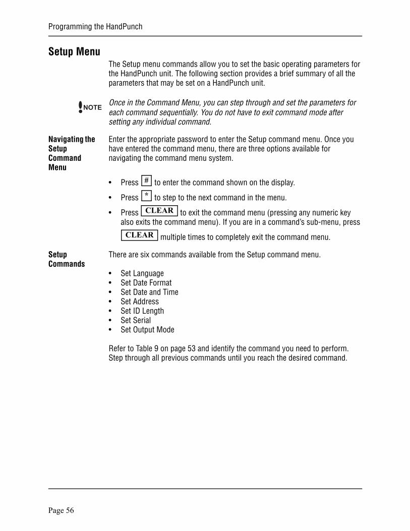
Setup MenuThe Setup menu commands allow you to set the basic operating parameters for the HandPunch unit. The following section provides a brief summary of all the parameters that may be set on a HandPunch unit.
Once in the Command Menu, you can step through and set the parameters for each command sequentially. You do not have to exit command mode after setting any individual command.
Navigating the Setup Command Menu
Enter the appropriate password to enter the Setup command menu. Once you have entered the command menu, there are three options available for navigating the command menu system.
• Press to enter the command shown on the display.
• Press to step to the next command in the menu.
• Press to exit the command menu (pressing any numeric key also exits the command menu). If you are in a command’s sub-menu, press
multiple times to completely exit the command menu.
Setup Commands
There are six commands available from the Setup command menu.
• Set Language• Set Date Format• Set Date and Time• Set Address• Set ID Length• Set Serial• Set Output Mode
Refer to Table 9 on page 53 and identify the command you need to perform. Step through all previous commands until you reach the desired command.
NOTE
#
*
CLEAR
CLEAR
Page 56
HandPunch 3000/4000 Manual
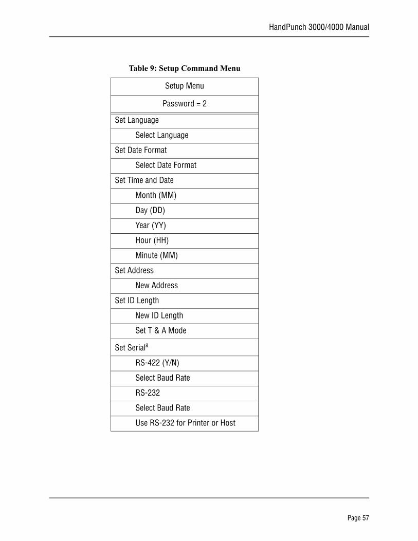
Table 9: Setup Command Menu
Setup Menu
Password = 2
Set Language
Select Language
Set Date Format
Select Date Format
Set Time and Date
Month (MM)
Day (DD)
Year (YY)
Hour (HH)
Minute (MM)
Set Address
New Address
Set ID Length
New ID Length
Set T & A Mode
Set Seriala
RS-422 (Y/N)
Select Baud Rate
RS-232
Select Baud Rate
Use RS-232 for Printer or Host
Page 57
Programming the HandPunch
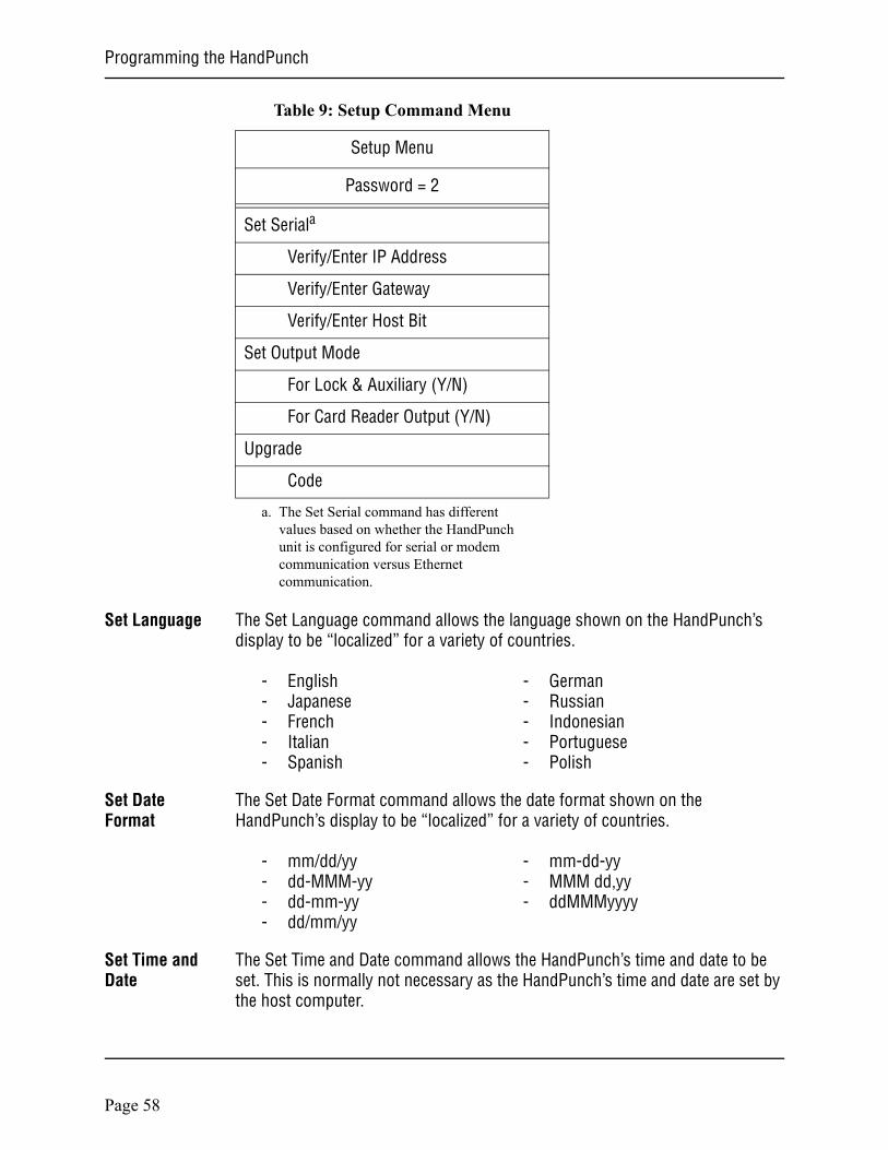
Set Language The Set Language command allows the language shown on the HandPunch’s display to be “localized” for a variety of countries.
- English - German- Japanese - Russian- French - Indonesian- Italian - Portuguese- Spanish - Polish
Set Date Format
The Set Date Format command allows the date format shown on the HandPunch’s display to be “localized” for a variety of countries.
- mm/dd/yy - mm-dd-yy- dd-MMM-yy - MMM dd,yy- dd-mm-yy - ddMMMyyyy- dd/mm/yy
Set Time and Date
The Set Time and Date command allows the HandPunch’s time and date to be set. This is normally not necessary as the HandPunch’s time and date are set by the host computer.
Set Seriala
Verify/Enter IP Address
Verify/Enter Gateway
Verify/Enter Host Bit
Set Output Mode
For Lock & Auxiliary (Y/N)
For Card Reader Output (Y/N)
Upgrade
Code
a. The Set Serial command has different values based on whether the HandPunch unit is configured for serial or modem communication versus Ethernet communication.
Table 9: Setup Command Menu
Setup Menu
Password = 2
Page 58

HandPunch 3000/4000 Manual
Set Address The Set Address command allows a unique address to be set for each HandPunch in a network. For proper operation, each HandPunch in the network must have a unique address. All units may use any address from 0 to 254. All units are sent with the address set to 1.
Set ID Length The Set ID Length command allows you to reduce the number of keystrokes
required to enter the ID number by eliminating the use of the key to complete an ID number entry. Once the ID Length is set, the HandPunch will automatically accept an ID number entry once the correct number of characters have been entered.
Set ID Length does not apply when ID entry is made from a card reader. Once the ID Length is set, the T & A Mode Set command appears, allowing you to configure the HandPunch to prepare punch data for time and attendance software.
Set Serial The Set Serial command allows you to set communication parameters depending upon the communication method for which the HandPunch has been configured. Different configuration parameters are entered based on if the unit is configured for a direct-connection or a modem connection, or if the unit is configured for Ethernet communication.
The unit defaults to the RS-422 communication mode unless a modem or Ethernet module has been installed. The unit defaults to 9600 bps which is suitable for most communication applications.
If an Ethernet module has been installed, the IP Address and Gateway and Subnet Mask must be set. The host bits should be left at 0, if communicating across a LAN.
Set Output Mode
The Set Output Mode command allows you to set how the output relays operate. The relays should be set based on the HandPunch application.
Set the HandPunch to Lock/Auxiliary Relay mode if the unit is acting as door controller (this is the factory default setting).Set the HandPunch to Card Reader Emulation mode if the unit is outputting to an access control panel.
Upgrade This Upgrade Menu is where the HandPunch code gets input to allow for a Memory Upgrade.
ENTER
Page 59
Programming the HandPunch
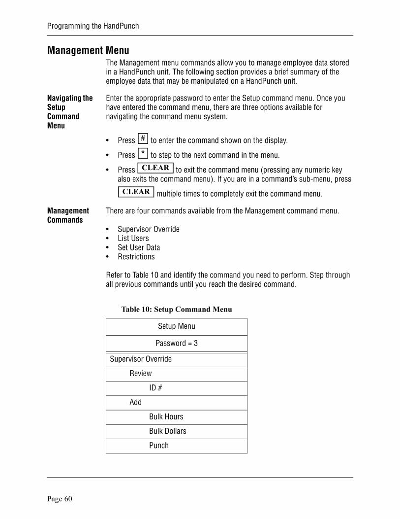
Management MenuThe Management menu commands allow you to manage employee data stored in a HandPunch unit. The following section provides a brief summary of the employee data that may be manipulated on a HandPunch unit.
Navigating the Setup Command Menu
Enter the appropriate password to enter the Setup command menu. Once you have entered the command menu, there are three options available for navigating the command menu system.
• Press to enter the command shown on the display.
• Press to step to the next command in the menu.
• Press to exit the command menu (pressing any numeric key also exits the command menu). If you are in a command’s sub-menu, press
multiple times to completely exit the command menu.
Management Commands
There are four commands available from the Management command menu.
• Supervisor Override• List Users• Set User Data• Restrictions
Refer to Table 10 and identify the command you need to perform. Step through all previous commands until you reach the desired command.
#
*
CLEAR
CLEAR
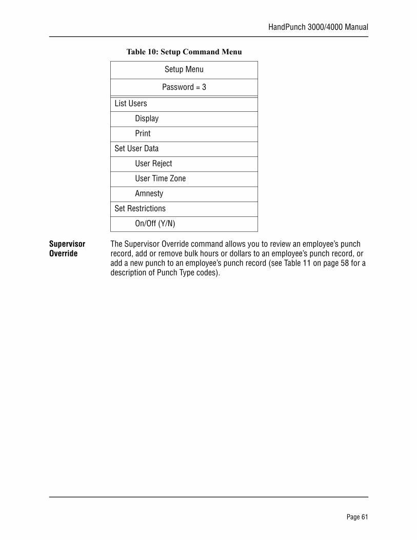
Table 10: Setup Command Menu
Setup Menu
Password = 3
Supervisor Override
Review
ID #
Add
Bulk Hours
Bulk Dollars
Punch
Page 60
HandPunch 3000/4000 Manual
Supervisor Override
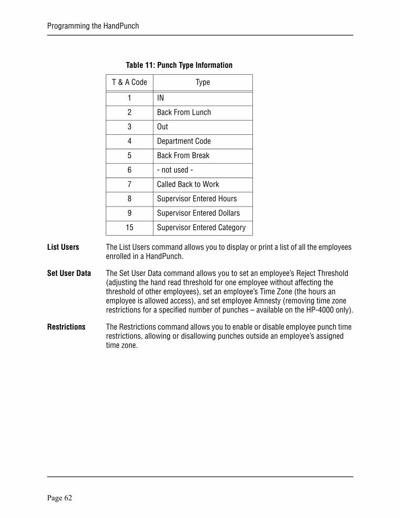
The Supervisor Override command allows you to review an employee’s punch record, add or remove bulk hours or dollars to an employee’s punch record, or add a new punch to an employee’s punch record (see Table 11 on page 58 for a description of Punch Type codes).
List Users
Display
Set User Data
User Reject
User Time Zone
Amnesty
Set Restrictions
On/Off (Y/N)
Table 10: Setup Command Menu
Setup Menu
Password = 3
Page 61
Programming the HandPunch
List Users The List Users command allows you to display or print a list of all the employees enrolled in a HandPunch.
Set User Data The Set User Data command allows you to set an employee’s Reject Threshold (adjusting the hand read threshold for one employee without affecting the threshold of other employees), set an employee’s Time Zone (the hours an employee is allowed access), and set employee Amnesty (removing time zone restrictions for a specified number of punches – available on the HP-4000 only).
Restrictions The Restrictions command allows you to enable or disable employee punch time restrictions, allowing or disallowing punches outside an employee’s assigned time zone.
Table 11: Punch Type Information
T & A Code Type
1 IN
2 Back From Lunch
3 Out
4 Department Code
5 Back From Break
6 - not used -
7 Called Back to Work
8 Supervisor Entered Hours
9 Supervisor Entered Dollars
15 Supervisor Entered Category
Page 62
HandPunch 3000/4000 Manual
Enrollment MenuEnrollment is the process of recording a hand image and associating it with an ID number. The first person to enroll in the HandPunch has access to all command menus. This person should enroll using the Add Supervisor command (see page 62). Once a supervisor has been enrolled, all further enrollments use the following rules:
• A user enrolled through the Add Employee command (page 62) is assigned Authority Level 0. This allows the user to punch in and/or gain access through a door secured by the HandPunch.
• A user enrolled through the Add Supervisor command (see page 62) is assigned Authority Level 5. This allows the supervisor to punch in and gain access through a door secured by the HandPunch, and it allows the supervisor to access all command menus.
Until a user has been assigned to Authority Level 5 using the Add Supervisor command, every user with Authority Level 0 can access every menu. This is done to ensure that the first person enrolled is able to access all the menus to perform all the programming required to support the HandPunch. Once a user has been enrolled using the Add Supervisor command, all further user authority levels are assigned as per the list above. This protects the integrity of the system by enacting the Authority Level rules described above. Recognition Systems strongly recommends enrolling at least two users as supervisors to ensure that more than one person has the authority to access all menus and all commands.
Advance planning and training make enrollment fast and easy. Users should be informed on what to expect and how to place their hands on the HandPunch before you enroll them.
Navigating the Setup Com-mand Menu
Enter the appropriate password to enter the Setup command menu. Once you have entered the command menu, there are three options available for navigating the command menu system.
• Press to enter the command shown on the display.
• Press to step to the next command in the menu.
• Press to exit the command menu (pressing any numeric key also exits the command menu). If you are in a command’s sub-menu, press
multiple times to completely exit the command menu.
NOTE
#
*
CLEAR
CLEAR
Page 63
Programming the HandPunch
Preparation Here are a few guidelines to help you prepare for an enrollment session.
• You can enroll one person or a group of people during an enrollment session.
• Each user must have a unique personal identification (ID) number. It will save you considerable time if you assign the ID numbers in advance (Refer to the Design an ID Numbering System section on page XX).
• The HandPunch will not accept two people with the same ID number.• If you enroll people using the last four digits of their phone numbers or
social security numbers, you may get duplicate numbers.• If you are enrolling large groups of people you may consider using an
enrollment trainer. It is a replica of a platen that is available through your Recognition Systems reseller.
User Education
The HandPunch is easy to use and non-threatening. However, most people have never used a biometric HandPunch. Training users on how the HandPunch works and how to use it will eliminate most fears and concerns before they occur. Inform the users of these facts.
• The HandPunch reads the shape of the hand, not the fingerprints or palmprints.
• It does not identify people. It confirms people’s identity.• It scans with an invisible light of the type used in TV remote controls.• It does not transfer germs any more than a doorknob or money.• It does not invade privacy; it guarantees it.• The enrollment process requires three or more reads to collect enough
information to create a template.
Proper Hand Placement
For correct, consistent hand reads it is very important that your hand is placed on the platen in the same manner every time. The following rules apply for proper hand placement on the platen also refer to Figure 8-2 bellow.
• If you are wearing a ring, rotate the ring so the stone faces up in its normal position.
• Slide your right hand onto the platen rather like an airplane landing at the airport.
• Slide your hand forward until the web between your index and middle finger stops against the Web Pin.
• Keep your hand flat. You should feel the surface of the platen on your palm and the underside of your fingers.
• Close your fingers together until they touch the Finger Pins and watch the hand diagram light display on the top panel.
• The lights go out when you have properly placed your fingers. If a light remains on, a finger is not in proper contact with its Finger Pin.
Page 64
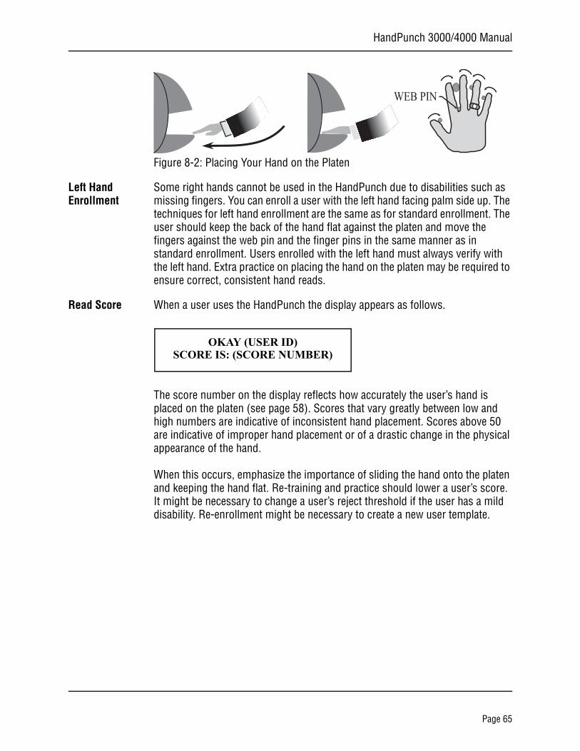
HandPunch 3000/4000 Manual
Figure 8-2: Placing Your Hand on the Platen
Left Hand Enrollment
Some right hands cannot be used in the HandPunch due to disabilities such as missing fingers. You can enroll a user with the left hand facing palm side up. The techniques for left hand enrollment are the same as for standard enrollment. The user should keep the back of the hand flat against the platen and move the fingers against the web pin and the finger pins in the same manner as in standard enrollment. Users enrolled with the left hand must always verify with the left hand. Extra practice on placing the hand on the platen may be required to ensure correct, consistent hand reads.
Read Score When a user uses the HandPunch the display appears as follows.
The score number on the display reflects how accurately the user’s hand is placed on the platen (see page 58). Scores that vary greatly between low and high numbers are indicative of inconsistent hand placement. Scores above 50 are indicative of improper hand placement or of a drastic change in the physical appearance of the hand.
When this occurs, emphasize the importance of sliding the hand onto the platen and keeping the hand flat. Re-training and practice should lower a user’s score. It might be necessary to change a user’s reject threshold if the user has a mild disability. Re-enrollment might be necessary to create a new user template.
WEB PIN
OKAY (USER ID)SCORE IS: (SCORE NUMBER)
Page 65
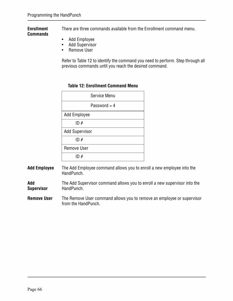
Programming the HandPunch
Enrollment Commands
There are three commands available from the Enrollment command menu.
• Add Employee• Add Supervisor• Remove User
Refer to Table 12 to identify the command you need to perform. Step through all previous commands until you reach the desired command.
Add Employee The Add Employee command allows you to enroll a new employee into the HandPunch.
Add Supervisor
The Add Supervisor command allows you to enroll a new supervisor into the HandPunch.
Remove User The Remove User command allows you to remove an employee or supervisor from the HandPunch.
Table 12: Enrollment Command Menu
Service Menu
Password = 4
Add Employee
ID #
Add Supervisor
ID #
Remove User
ID #
Page 66
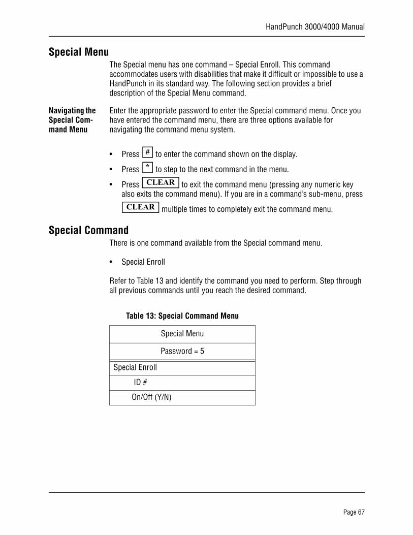
HandPunch 3000/4000 Manual
Special MenuThe Special menu has one command – Special Enroll. This command accommodates users with disabilities that make it difficult or impossible to use a HandPunch in its standard way. The following section provides a brief description of the Special Menu command.
Navigating the Special Com-mand Menu
Enter the appropriate password to enter the Special command menu. Once you have entered the command menu, there are three options available for navigating the command menu system.
• Press to enter the command shown on the display.
• Press to step to the next command in the menu.
• Press to exit the command menu (pressing any numeric key also exits the command menu). If you are in a command’s sub-menu, press
multiple times to completely exit the command menu.
Special CommandThere is one command available from the Special command menu.
• Special Enroll
Refer to Table 13 and identify the command you need to perform. Step through all previous commands until you reach the desired command.
#
*
CLEAR
CLEAR
Table 13: Special Command Menu
Special Menu
Password = 5
Special Enroll
ID #
On/Off (Y/N)
Page 67
Programming the HandPunch
Special Enroll The Special Enroll command allows a user to be enrolled such that the ID number is the primary criteria for determining access. A hand read is required, but is not verified against any stored identification data. A time zone value can be applied to the Special Enrollment ID number to limit access times (see page 58). The HandPunch default is for no time zone to be applied.
Special Enrollment affects the integrity of the HandPunch terminal and should only be used as a last resort. Anyone who knows a Special Enroll ID number is granted access when the ID number is used. Before specially enrolling a user, try to alleviate verification problems by adjusting the individual user’s reject threshold (see page 58) or by using left hand enrollment (see page 61).
NOTE
Page 68
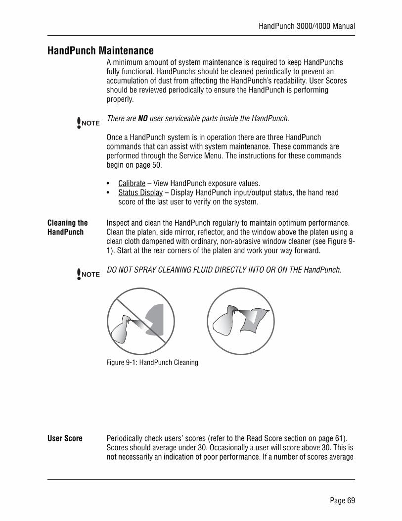
HandPunch 3000/4000 Manual
HandPunch MaintenanceA minimum amount of system maintenance is required to keep HandPunchs fully functional. HandPunchs should be cleaned periodically to prevent an accumulation of dust from affecting the HandPunch’s readability. User Scores should be reviewed periodically to ensure the HandPunch is performing properly.
There are NO user serviceable parts inside the HandPunch.
Once a HandPunch system is in operation there are three HandPunch commands that can assist with system maintenance. These commands are performed through the Service Menu. The instructions for these commands begin on page 50.
• Calibrate – View HandPunch exposure values.• Status Display – Display HandPunch input/output status, the hand read
score of the last user to verify on the system.
Cleaning the HandPunch
Inspect and clean the HandPunch regularly to maintain optimum performance. Clean the platen, side mirror, reflector, and the window above the platen using a clean cloth dampened with ordinary, non-abrasive window cleaner (see Figure 9-1). Start at the rear corners of the platen and work your way forward.
DO NOT SPRAY CLEANING FLUID DIRECTLY INTO OR ON THE HandPunch.
Figure 9-1: HandPunch Cleaning
User Score Periodically check users’ scores (refer to the Read Score section on page 61). Scores should average under 30. Occasionally a user will score above 30. This is not necessarily an indication of poor performance. If a number of scores average
NOTE
NOTE
Page 69

Maintence
over 30, clean the HandPunch and check scores again. If scores remain high, or if users are experiencing frequent rejections, run the Calibration command (see page 50).
Page 70

HandPunch 3000/4000 Manual
Appendix A
Tips for a successful Installation
HandPunch
• Think of the HandPunch as a camera• Clean the HandPunch before it gets dirty• Use non-abrasive cleaners such as glass cleaners and non-abrasive and
clean cloths• Make cleaning the HandPunch part of Janitorial program• Do not remove the foam backing from the wall mounting plate• Seal any holes made in the wall for wire routing, so that dust will not
blow into the HandPunch
Location
• Mount all HandPunchs in a network so that the top of the platen is 40” off of the floor
• If an enrollment HandPunch is used make sure that it is placed with the top platen 40” off of the floor and not sitting directly on top of a desk, this will help to eliminate “bad enrollments”
• Mount the HandPunch so that it is not difficult or dangerous to verify then open the door
• It is not recommended to mount the HandPunch in an area where there is airborne dust, in the path of direct sunlight, or where the HandPunch can be exposed to water or corrosive gasses
Enrollment
• Educate the Enrollee on Hand Geometry• Explain enrollment process• Train Enrollee on hand placement
-Practice placing hand on platen-Make sure hand is flat on platen-Close finger towards the center of hand-Fingers gently touch finger pins
• Let the enrollee enter in their own ID number during the enrollment pro-cess, this forces the Enroller to step aside allowing the Enrollee to stand in front of the HandPunch helping to eliminate “bad enrollments”
Page 71
Appendix A - Tips
Communication
• Make sure the Data Convertor is plugged in• When starting a network for the first time bring one HandPunch up at a
time, this is a very easy way to find out where communication problems may exist
Page 72
HandPunch 3000/4000 Manual
Appendix B
Noted Board Configuration Differences
Because of Recognition Systems’ camera retrofit of the HandPunch some changes have been made to the main PCB and they are listed as follows:
• Dipswitches have been removed-comm lines are terminated-RS-485 is set by wiring jumpers-memory is reset with a push-button reset and user interface with
keypad and LCD• The labeling of the terminal strips have changed. See Figure 16-1• The configuration of the terminal strips have changed. See Figure 16-2• Power has moved to the right side of the PCB• The RSS-232 RJ-45 receptacle has been replaced with a 4 pin Molex
connector on the left side of the PCB• A 2 pin Molex connector (J5) has been added to the board, next to the
reset button, to supply power for the LEDs. This connector should never be unplugged. unless a modem or Ethernet is added to the PCB
• The upgrading of the memory is now handled through software codes at the HandPunch. Contact Order Entry for memory upgrades
Page 73
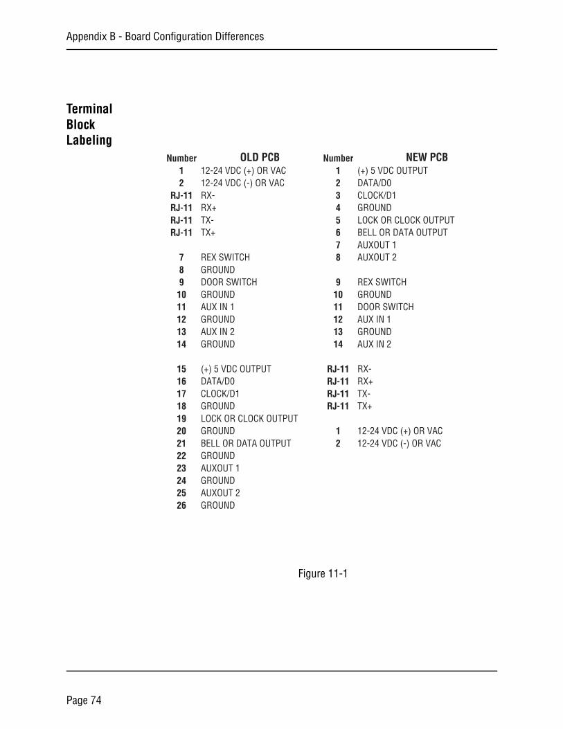
Appendix B - Board Configuration Differences
Terminal Block Labeling
Figure 11-1
Number OLD PCB Number NEW PCB1 12-24 VDC (+) OR VAC 1 (+) 5 VDC OUTPUT2 12-24 VDC (-) OR VAC 2 DATA/D0
RJ-11 RX- 3 CLOCK/D1RJ-11 RX+ 4 GROUNDRJ-11 TX- 5 LOCK OR CLOCK OUTPUTRJ-11 TX+ 6 BELL OR DATA OUTPUT
7 AUXOUT 17 REX SWITCH 8 AUXOUT 28 GROUND9 DOOR SWITCH 9 REX SWITCH
10 GROUND 10 GROUND11 AUX IN 1 11 DOOR SWITCH12 GROUND 12 AUX IN 113 AUX IN 2 13 GROUND14 GROUND 14 AUX IN 2
15 (+) 5 VDC OUTPUT RJ-11 RX-16 DATA/D0 RJ-11 RX+17 CLOCK/D1 RJ-11 TX-18 GROUND RJ-11 TX+19 LOCK OR CLOCK OUTPUT20 GROUND 1 12-24 VDC (+) OR VAC21 BELL OR DATA OUTPUT 2 12-24 VDC (-) OR VAC22 GROUND23 AUXOUT 124 GROUND25 AUXOUT 226 GROUND
Page 74
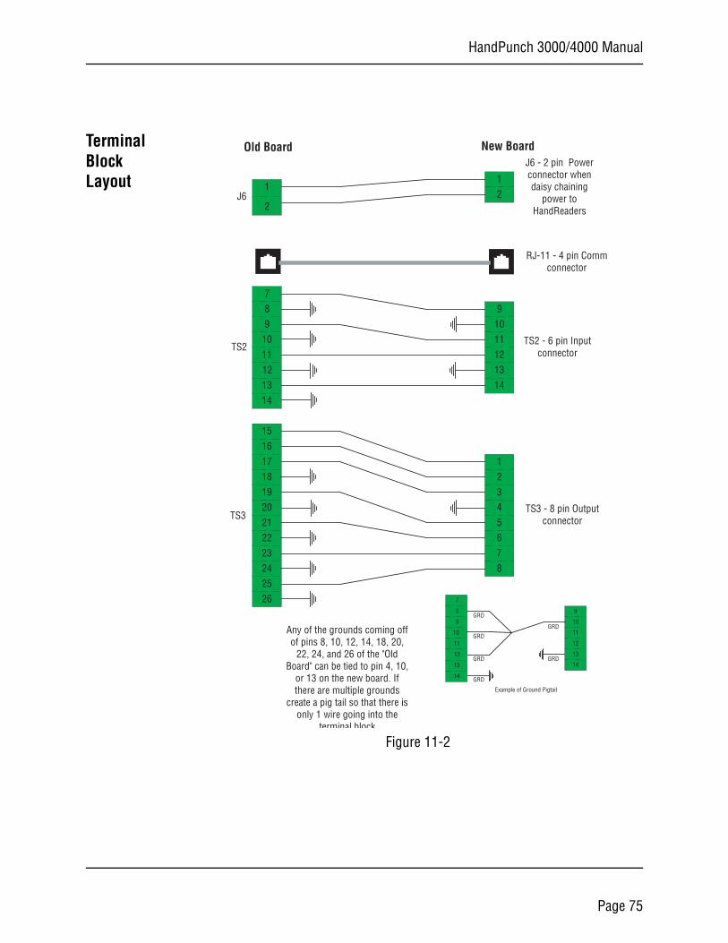
HandPunch 3000/4000 Manual
Terminal Block Layout
Figure 11-2
1
2
8
109
12
7
13
11
14
15
1716
1918
24
21
23
20
22
2625
1
21
9
1314
101112
45678
23
J6 - 2 pin Powerconnector whendaisy chaining
power toHandReaders
TS2 - 6 pin Inputconnector
RJ-11 - 4 pin Commconnector
TS3 - 8 pin Outputconnector
8
10
9
12
7
13
11
14
9
13
14
10
11
12
GRD
GRD
GRD
GRD
GRD
GRD
Example of Ground Pigtail
Old Board New Board
Any of the grounds coming offof pins 8, 10, 12, 14, 18, 20,
22, 24, and 26 of the "OldBoard" can be tied to pin 4, 10,
or 13 on the new board. Ifthere are multiple grounds
create a pig tail so that there isonly 1 wire going into the
terminal block
TS3
TS2
J6
Page 75
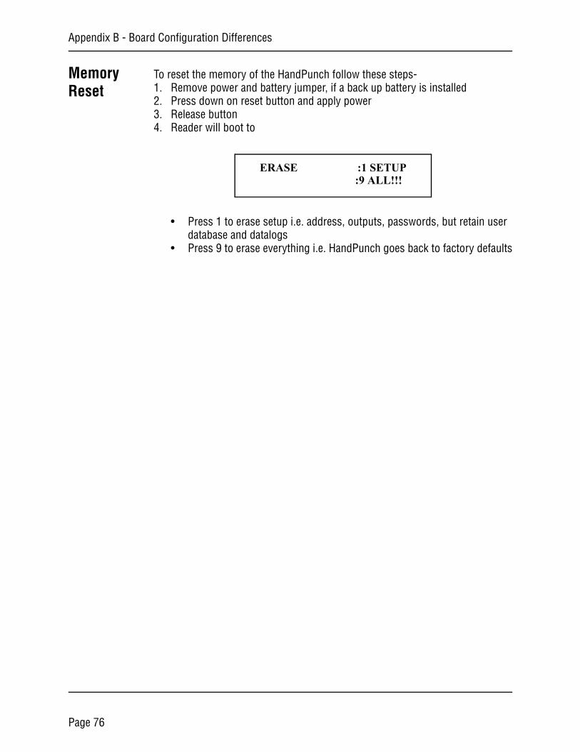
Appendix B - Board Configuration Differences
Memory Reset
To reset the memory of the HandPunch follow these steps-1. Remove power and battery jumper, if a back up battery is installed2. Press down on reset button and apply power3. Release button4. Reader will boot to
• Press 1 to erase setup i.e. address, outputs, passwords, but retain user database and datalogs
• Press 9 to erase everything i.e. HandPunch goes back to factory defaults
ERASE :1 SETUP :9 ALL!!!
Page 76
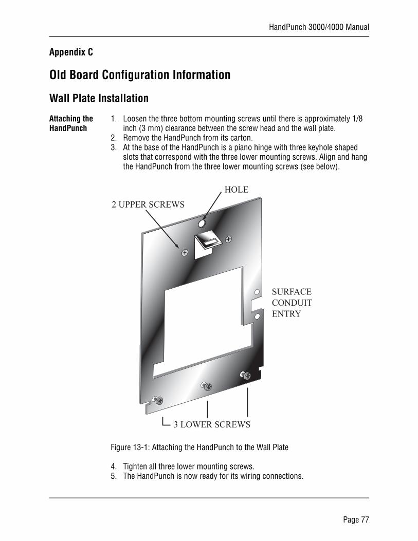
HandPunch 3000/4000 Manual
Appendix C
Old Board Configuration Information
Wall Plate Installation
Attaching the HandPunch
1. Loosen the three bottom mounting screws until there is approximately 1/8 inch (3 mm) clearance between the screw head and the wall plate.
2. Remove the HandPunch from its carton.3. At the base of the HandPunch is a piano hinge with three keyhole shaped
slots that correspond with the three lower mounting screws. Align and hang the HandPunch from the three lower mounting screws (see below).
Figure 13-1: Attaching the HandPunch to the Wall Plate
4. Tighten all three lower mounting screws.5. The HandPunch is now ready for its wiring connections.
2 UPPER SCREWS
3 LOWER SCREWS
HOLE
SURFACECONDUITENTRY
Page 77
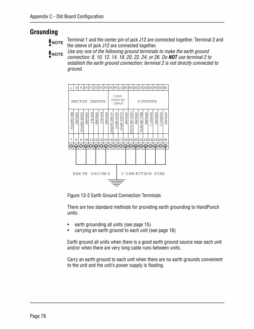
Appendix C - Old Board Configuration
GroundingTerminal 1 and the center pin of jack J12 are connected together. Terminal 2 and the sleeve of jack J12 are connected together.Use any one of the following ground terminals to make the earth ground connection: 8, 10, 12, 14, 18, 20, 22, 24, or 26. Do NOT use terminal 2 to establish the earth ground connection; terminal 2 is not directly connected to ground.
Figure 13-2 Earth Ground Connection Terminals
There are two standard methods for providing earth grounding to HandPunch units:
• earth grounding all units (see page 15)• carrying an earth ground to each unit (see page 16)
Earth ground all units when there is a good earth ground source near each unit and/or when there are very long cable runs between units.
Carry an earth ground to each unit when there are no earth grounds convenient to the unit and the unit’s power supply is floating.
NOTE
NOTE
7 8 9 10 11 12 13 14 15 16 17 18 19 20 21 22 23 24 25 26
7 8 9 10 11 12 13 14 15 16 17 18 19 20 21 22 23 24 2625
SWITCH INPUTS OUTPUTS
CARDREAD ERINPUT
RE
X S
WITC
H
GR
OU
ND
DO
OR
SW
ITCH
GR
OU
ND
AU
X IN
1
GR
OU
ND
GR
OU
ND
GR
OU
ND
GR
OU
ND
GR
OU
ND
GR
OU
ND
GR
OU
ND
AU
X IN
2
+5 VD
C O
UTP
UT
DA
TA IN
PU
T
CLO
CK
INP
UT
LOC
K O
R C
LOC
K
BE
LL OR
DA
TA
AU
XO
UT 1
AU
XO
UT 2
EAR TH GROUN D C ONN ECTION PINS
Page 78
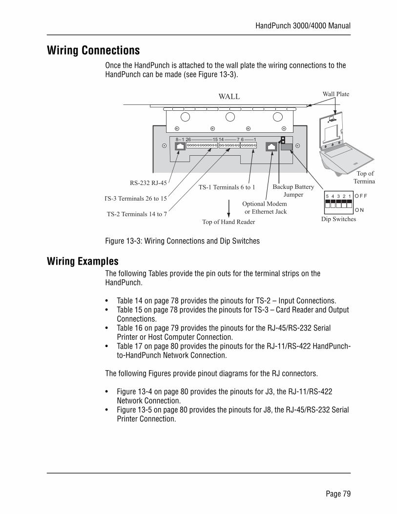
HandPunch 3000/4000 Manual
N
F F
Top oferminal
Wiring ConnectionsOnce the HandPunch is attached to the wall plate the wiring connections to the HandPunch can be made (see Figure 13-3).
Figure 13-3: Wiring Connections and Dip Switches
Wiring ExamplesThe following Tables provide the pin outs for the terminal strips on the HandPunch.
• Table 14 on page 78 provides the pinouts for TS-2 – Input Connections.• Table 15 on page 78 provides the pinouts for TS-3 – Card Reader and Output
Connections.• Table 16 on page 79 provides the pinouts for the RJ-45/RS-232 Serial
Printer or Host Computer Connection.• Table 17 on page 80 provides the pinouts for the RJ-11/RS-422 HandPunch-
to-HandPunch Network Connection.
The following Figures provide pinout diagrams for the RJ connectors.
• Figure 13-4 on page 80 provides the pinouts for J3, the RJ-11/RS-422 Network Connection.
• Figure 13-5 on page 80 provides the pinouts for J8, the RJ-45/RS-232 Serial Printer Connection.
WALL
O
O5 4 3 2 1
RS-232 RJ-45
TS-3 Terminals 26 to 15
TS-2 Terminals 14 to 7
TS-1 Terminals 6 to 1
Optional Modemor Ethernet Jack
Dip Switches
Wall Plate
T
Top of Hand Reader
14 7 6 11526
Backup BatteryJumper
8 1
Page 79
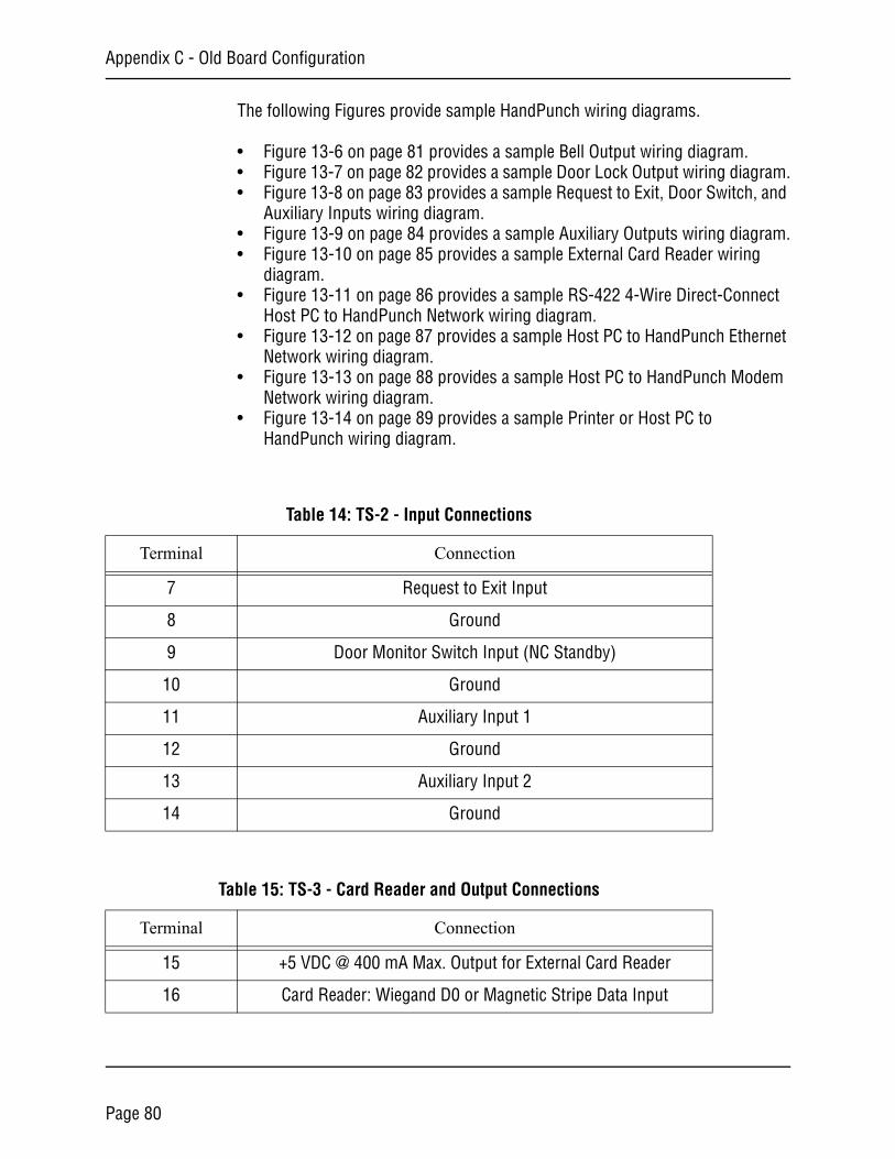
Appendix C - Old Board Configuration
The following Figures provide sample HandPunch wiring diagrams.
• Figure 13-6 on page 81 provides a sample Bell Output wiring diagram.• Figure 13-7 on page 82 provides a sample Door Lock Output wiring diagram.• Figure 13-8 on page 83 provides a sample Request to Exit, Door Switch, and
Auxiliary Inputs wiring diagram.• Figure 13-9 on page 84 provides a sample Auxiliary Outputs wiring diagram.• Figure 13-10 on page 85 provides a sample External Card Reader wiring
diagram.• Figure 13-11 on page 86 provides a sample RS-422 4-Wire Direct-Connect
Host PC to HandPunch Network wiring diagram.• Figure 13-12 on page 87 provides a sample Host PC to HandPunch Ethernet
Network wiring diagram.• Figure 13-13 on page 88 provides a sample Host PC to HandPunch Modem
Network wiring diagram.• Figure 13-14 on page 89 provides a sample Printer or Host PC to
HandPunch wiring diagram.
Table 14: TS-2 - Input Connections
Terminal Connection
7 Request to Exit Input
8 Ground
9 Door Monitor Switch Input (NC Standby)
10 Ground
11 Auxiliary Input 1
12 Ground
13 Auxiliary Input 2
14 Ground
Table 15: TS-3 - Card Reader and Output Connections
Terminal Connection
15 +5 VDC @ 400 mA Max. Output for External Card Reader
16 Card Reader: Wiegand D0 or Magnetic Stripe Data Input
Page 80
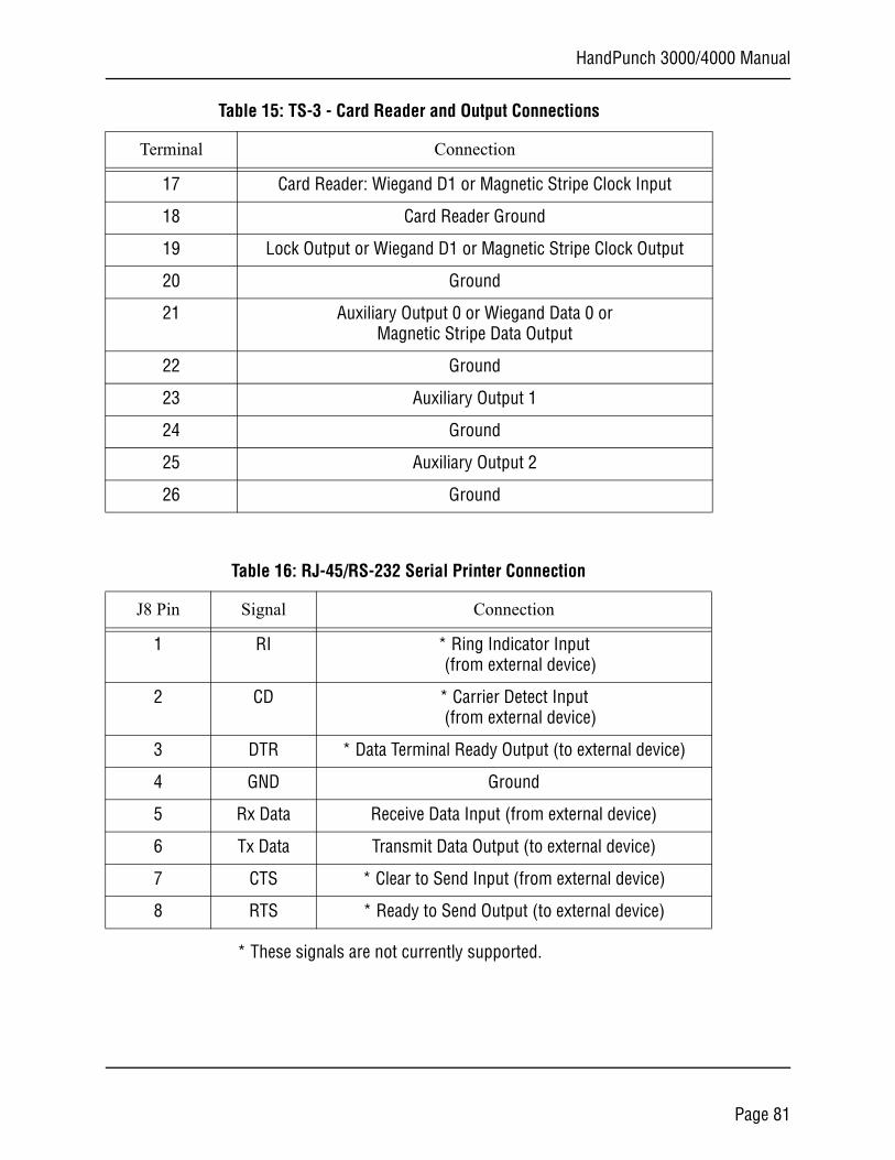
HandPunch 3000/4000 Manual
* These signals are not currently supported.
17 Card Reader: Wiegand D1 or Magnetic Stripe Clock Input
18 Card Reader Ground
19 Lock Output or Wiegand D1 or Magnetic Stripe Clock Output
20 Ground
21 Auxiliary Output 0 or Wiegand Data 0 or Magnetic Stripe Data Output
22 Ground
23 Auxiliary Output 1
24 Ground
25 Auxiliary Output 2
26 Ground
Table 15: TS-3 - Card Reader and Output Connections
Terminal Connection
Table 16: RJ-45/RS-232 Serial Printer Connection
J8 Pin Signal Connection
1 RI * Ring Indicator Input (from external device)
2 CD * Carrier Detect Input (from external device)
3 DTR * Data Terminal Ready Output (to external device)
4 GND Ground
5 Rx Data Receive Data Input (from external device)
6 Tx Data Transmit Data Output (to external device)
7 CTS * Clear to Send Input (from external device)
8 RTS * Ready to Send Output (to external device)
Page 81
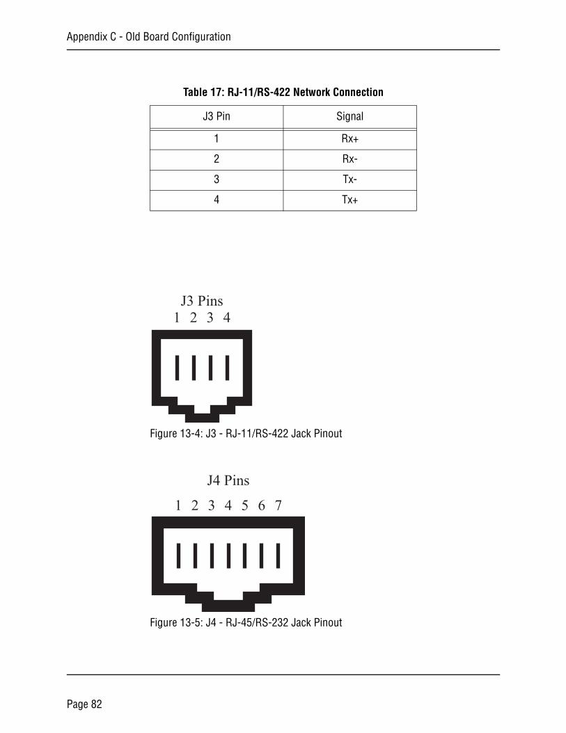
Appendix C - Old Board Configuration
Figure 13-4: J3 - RJ-11/RS-422 Jack Pinout
Figure 13-5: J4 - RJ-45/RS-232 Jack Pinout
Table 17: RJ-11/RS-422 Network Connection
J3 Pin Signal
1 Rx+
2 Rx-
3 Tx-
4 Tx+
J3 Pins1 2 3 4
1 2 3 4 5 6 7
J4 Pins
Page 82
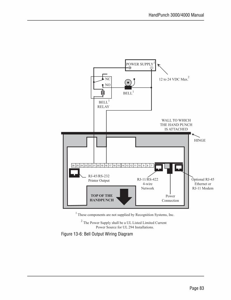
HandPunch 3000/4000 Manual
J-45orem
Figure 13-6: Bell Output Wiring Diagram
26 25 24 23 22 21 20 19 18 17 16 15 14 13 12 11 10 9 8 7
PowerConnection
TOP OF THEHANDPUNCH
HINGE
WALL TO WHICHTHE HAND PUNCH
IS ATTACHED
+ -POWER SUPPLY
RJ-45/RS-232Printer Output RJ-11/RS-422
4-wireNetwork
Optional REthernet
RJ-11 Mod
NCNO
BELLRELAY
BELL
12 to 24 VDC Max.
1
2
1
1
These components are not supplied by Recognition Systems, Inc.1
2 The Power Supply shall be a UL Listed Limited CurrentPower Source for UL 294 Installations.
Page 83
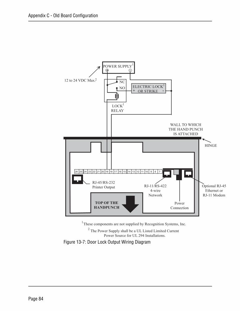
Appendix C - Old Board Configuration
RJ-45et orodem
Figure 13-7: Door Lock Output Wiring Diagram
26 25 24 23 22 21 20 19 18 17 16 15 14 13 12 11 10 9 8 7
PowerConnection
TOP OF THEHANDPUNCH
HINGE
WALL TO WHICHTHE HAND PUNCH
IS ATTACHED
+ -POWER SUPPLY
NCNO
LOCKRELAY
ELECTRIC LOCKOR STRIKE+ -
RJ-45/RS-232Printer Output RJ-11/RS-422
4-wireNetwork
OptionalEthern
RJ-11 M
12 to 24 VDC Max.
2 The Power Supply shall be a UL Listed Limited CurrentPower Source for UL 294 Installations.
These components are not supplied by Recognition Systems, Inc.1
1
1
1
2
Page 84
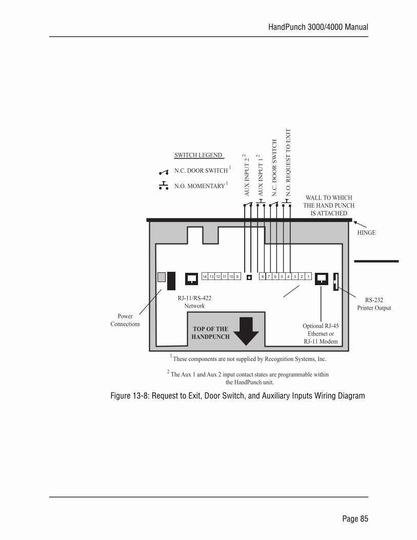
HandPunch 3000/4000 Manual
32Output
Figure 13-8: Request to Exit, Door Switch, and Auxiliary Inputs Wiring Diagram
14 13 12 11 10 9 8 7 6 5 4 3 2 1
PowerConnections
These components are not supplied by Recognition Systems, Inc.
The Aux 1 and Aux 2 input contact states are programmable withinthe HandPunch unit.
TOP OF THEHANDPUNCH
HINGE
WALL TO WHICHTHE HAND PUNCH
IS ATTACHED
AU
X IN
PUT
2
AU
X IN
PUT
1
N.C
. DO
OR
SW
ITC
H
N.O
. RE
QU
EST
TO
EX
IT
SWITCH LEGEND
N.C. DOOR SWITCH
N.O. MOMENTARY
RS-2Printer
RJ-11/RS-422Network
Optional RJ-45Ethernet or
RJ-11 Modem
1
2
1
1
2 2
Page 85
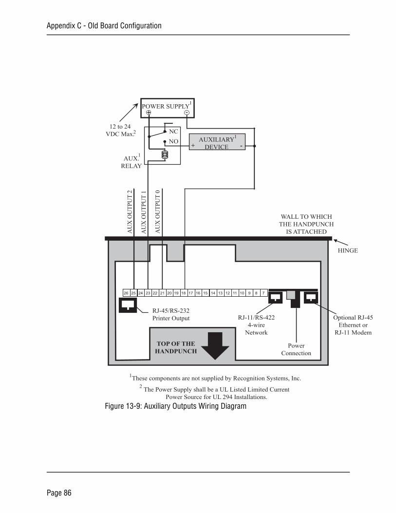
Appendix C - Old Board Configuration
RJ-45et orodem
Figure 13-9: Auxiliary Outputs Wiring Diagram
26 25 24 23 22 21 20 19 18 17 16 15 14 13 12 11 10 9 8 7
These components are not supplied by Recognition Systems, Inc.
TOP OF THEHANDPUNCH
HINGE
WALL TO WHICHTHE HANDPUNCH
IS ATTACHEDAU
X O
UTP
UT
2
AU
X O
UTP
UT
1
+ -POWER SUPPLY
AUX.RELAY
NCNO + -
AUXILIARYDEVICE
PowerConnection
RJ-11/RS-4224-wire
Network
OptionalEthern
RJ-11 M
RJ-45/RS-232Printer Output
AU
X O
UTP
UT
0
12 to 24VDC Max.
2 The Power Supply shall be a UL Listed Limited CurrentPower Source for UL 294 Installations.
1
1
1
1
2
Page 86
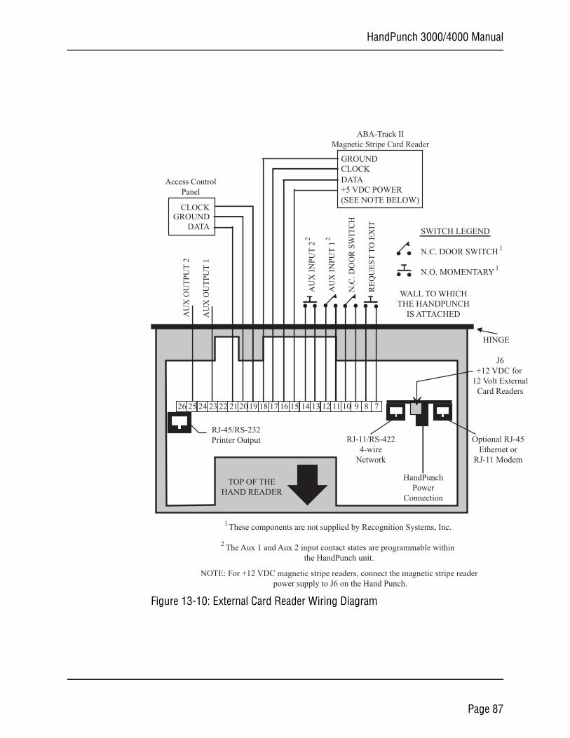
HandPunch 3000/4000 Manual
-45r
em
or rnalers
Figure 13-10: External Card Reader Wiring Diagram
26 25 24 23 22 21 20 19 18 17 16 15 14 13 12 11 10 9 8 7
These components are not supplied by Recognition Systems, Inc.
The Aux 1 and Aux 2 input contact states are programmable withinthe HandPunch unit.
TOP OF THEHAND READER
HINGE
WALL TO WHICHTHE HANDPUNCH
IS ATTACHEDAU
X O
UTP
UT
2
AU
X O
UTP
UT
1
AU
X IN
PUT
2
AU
X IN
PUT
1
N.C
. DO
OR
SW
ITC
H
REQ
UES
T TO
EX
IT SWITCH LEGEND
N.C. DOOR SWITCH
N.O. MOMENTARY
GROUNDCLOCK
CLOCKGROUND
DATA
DATA+5 VDC POWER(SEE NOTE BELOW)
NOTE: For +12 VDC magnetic stripe readers, connect the magnetic stripe reader power supply to J6 on the Hand Punch.
Access ControlPanel
ABA-Track IIMagnetic Stripe Card Reader
HandPunchPower
Connection
RJ-11/RS-4224-wire
Network
Optional RJEthernet o
RJ-11 Mod
RJ-45/RS-232Printer Output
J6+12 VDC f
12 Volt ExteCard Read
1
2
1
2 2
1
Page 87
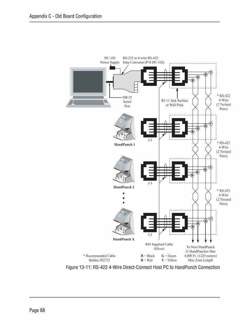
Appendix C - Old Board Configuration
-422ireistedrs)
-422ireistedrs)
-422ireistedrs)
Figure 13-11: RS-422 4-Wire Direct-Connect Host PC to HandPunch Connection
54
6F18
7
9F20
NoEnter
21
3Clear
*
#Yes
No
Recognition Systems Inc.
HandPunch 1
54
6F18
7
9F20
NoEnter
21
3Clear
*
#Yes
No
Recognition Systems Inc.
HandPunch 2
54
6F18
7
9F20
NoEnter
21
3Clear
*
#Yes
No
Recognition Systems Inc.
HandPunch X
DB-25SerialPort
DC-102Power Supply
RS-232 to 4-wire RS-422Data Converter (P/N DC-102)
RSI Supplied Cable(Silver)
RJ-11 Jack Surfaceor Wall Plate
* RS4-W
(2 TwPai
RG
Y
B
RG
Y
B
RG
Y
B
BR
GY
To Next HandPunch31 HandPunches Max
4,000 Ft. (1220 meters)Max Zone Length
* Recommended CableBelden #82723
* RS4-W
(2 TwPai
* RS4-W
(2 TwPai
B = BlackR = Red
G = GreenY = Yellow
J-3
J-3
J-3
Page 88
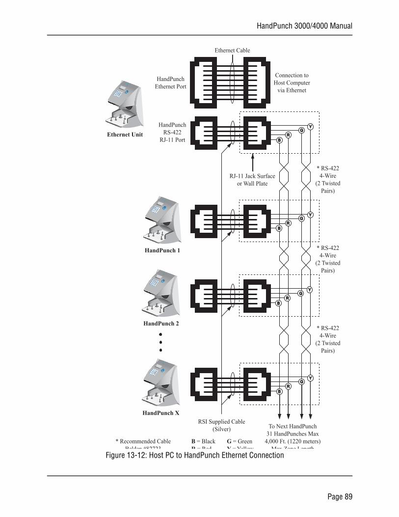
HandPunch 3000/4000 Manual
Figure 13-12: Host PC to HandPunch Ethernet Connection
54
6F18
7
9F20
NoEnter
21
3Clear
*
#Yes
No
Recognition Systems Inc.
HandPunch 1
54
6F18
7
9F20
NoEnter
21
3Clear
*
#Yes
No
Recognition Systems Inc.
HandPunch 2
54
6F18
7
9F20
NoEnter
21
3Clear
*
#Yes
No
Recognition Systems Inc.
HandPunch XRSI Supplied Cable
(Silver)
RJ-11 Jack Surfaceor Wall Plate
RG
Y
B
RG
Y
B
RG
Y
B
BR
GY
To Next HandPunch31 HandPunches Max
4,000 Ft. (1220 meters)Max Zone Length
* Recommended CableBelden #82723
54
6F18
7
9F20
NoEnter
21
3Clear
*
#Yes
No
Recognition Systems Inc.
Ethernet UnitHandPunch
RS-422RJ-11 Port
HandPunchEthernet Port
Ethernet Cable
Connection toHost Computer
via Ethernet
* RS-4224-Wire
(2 TwistedPairs)
* RS-4224-Wire
(2 TwistedPairs)
* RS-4224-Wire
(2 TwistedPairs)
B = BlackR = Red
G = GreenY = Yellow
Page 89
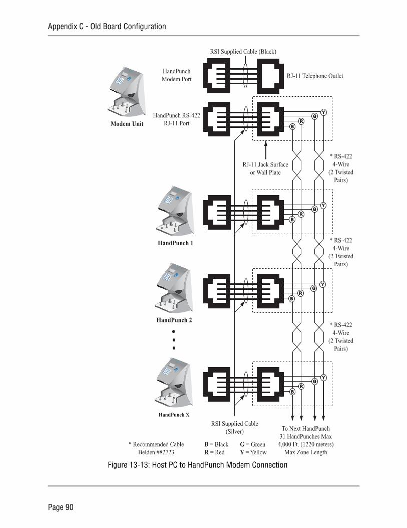
Appendix C - Old Board Configuration
Figure 13-13: Host PC to HandPunch Modem Connection
54
6F18
7
9F20
NoEnter
21
3Clear
*
#Yes
No
Recognition Systems Inc.
HandPunch 1
54
6F18
7
9F20
NoEnter
21
3Clear
*
#Yes
No
Recognition Systems Inc.
HandPunch 2
54
6F18
7
9F20
NoEnter
21
3Clear
*
#Yes
No
Recognition Systems Inc.
HandPunch X
RSI Supplied Cable(Silver)
RJ-11 Jack Surfaceor Wall Plate
RG
Y
B
RG
Y
B
RG
Y
B
BR
GY
To Next HandPunch31 HandPunches Max
4,000 Ft. (1220 meters)Max Zone Length
* Recommended CableBelden #82723
54
6F18
7
9F20
NoEnter
21
3Clear
*
#Yes
No
Recognition Systems Inc.
Modem UnitHandPunch RS-422
RJ-11 Port
HandPunchModem Port
RSI Supplied Cable (Black)
RJ-11 Telephone Outlet
* RS-4224-Wire
(2 TwistedPairs)
* RS-4224-Wire
(2 TwistedPairs)
* RS-4224-Wire
(2 TwistedPairs)
B = BlackR = Red
G = GreenY = Yellow
Page 90
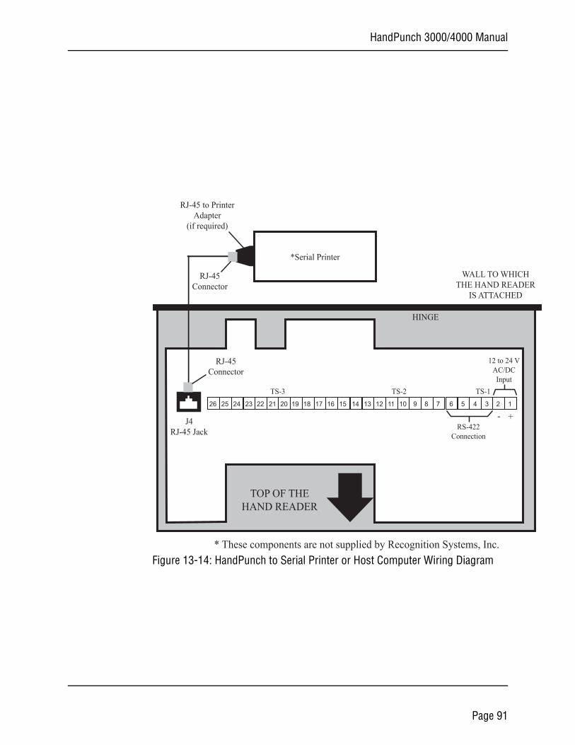
HandPunch 3000/4000 Manual
CHDER
Figure 13-14: HandPunch to Serial Printer or Host Computer Wiring Diagram
26 25 24 23 22 21 20 19 18 17 16 15 14 13 12 11 10 9 8 7 6 5 4 3 2 1
RS-422Connection
12 to 24 VAC/DCInput
+-
* These components are not supplied by Recognition Systems, Inc.
TOP OF THEHAND READER
HINGE
WALL TO WHITHE HAND REA
IS ATTACHED
TS-1TS-2TS-3
J4RJ-45 Jack
*Serial Printer
RJ-45Connector
RJ-45Connector
RJ-45 to PrinterAdapter
(if required)
Page 91
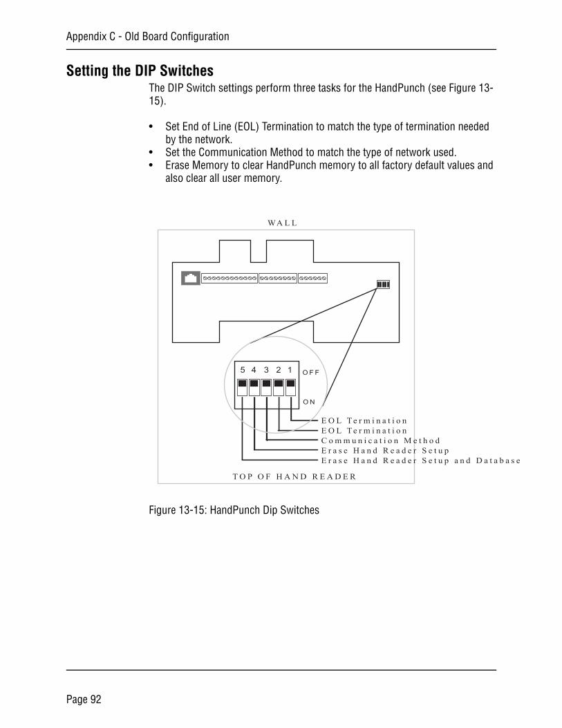
Appendix C - Old Board Configuration
a s e
Setting the DIP SwitchesThe DIP Switch settings perform three tasks for the HandPunch (see Figure 13-15).
• Set End of Line (EOL) Termination to match the type of termination needed by the network.
• Set the Communication Method to match the type of network used.• Erase Memory to clear HandPunch memory to all factory default values and
also clear all user memory.
Figure 13-15: HandPunch Dip Switches
O N
O F F
WA L L
T O P O F H A N D R E A D E R
E O L T e r m i n a t i o nE O L T e r m i n a t i o nC o m m u n i c a t i o n M e t h o dE r a s e H a n d R e a d e r S e t u pE r a s e H a n d R e a d e r S e t u p a n d D a t a b
12345
Page 92
HandPunch 3000/4000 Manual
End of Line Termination
Termination helps to ensure clean data signals are transmitted through the network wiring. Termination is applied to the end-of-line (EOL) HandPunch in the network daisy-chain. The factory default setting is for EOL termination to be disabled – switches 1 and 2 OFF. Refer to Figure 13-15 on page 90 for switch ON/OFF positioning.
• To enable EOL termination at a HandPunch, both switches 1 and 2 must be ON.
• To disable EOL termination at a HandPunch, both switches 1 and 2 must be OFF.
EOL Termination must be enabled for:• A single HandPunch terminal installation.• In a HandPunch Direct-Connect network – the last HandPunch in the daisy-
chain (the one farthest from the host computer).• In a Modem/HandPunch to PC network the HandPunch terminal with the
Modem option (for communication with the host computer) in the daisy-chain.
EOL Termination must be disabled for:• All HandPunchs in the network not identified in the previous section.• In an Ethernet/HandPunch to PC network the HandPunch terminal with the
Ethernet option (for communication with the host computer) in the daisy-chain.
Communication MethodThe communication method dip switch is set ON for factory testing purposes. The factory default setting and for standard operation, switch 3 must be OFF.
• Switch 3 must always be OFF.
Erasing HandPunch MemoryThe erase memory function can perform either or both of the following:
• Erase a HandPunch’s configuration data.• Erase a HandPunch’s user database, transaction buffer, and menus (and
messages on the HandPunch 4000).
The factory default setting (and normal operation setting) is for switches 4 and 5 to be OFF, retaining memory.
If the HandPunch is equipped with the battery backup option, remove shunt J7 in front of the DIP switch array (see Figure 13-3 on page 77) before proceeding. Replace shunt J7 after completion of the following steps.
NOTE
Page 93
Appendix C - Old Board Configuration
Erasing the HandPunch Setup
Perform the following steps to erase the configuration data but retain the user database.
1. With system power OFF, set switch 4 ON.2. Turn system power ON and wait for HandPunch boot information to appear
on the display.3. Turn switch 4 OFF.
Erasing the HandPunch Setup and User Database
Perform the following steps to erase both the configuration data and the user database.
1. With system power OFF, set both switches 4 and 5 ON.2. Turn system power ON and wait 5 seconds.3. Turn both switches 4 and 5 OFF.
Before putting the HandPunch into service ensure DIP switches 4 and 5 are both OFF. If switches 4 and 5 are not off, the next time the HandPunch’s power is cycled the HandPunch’s memory will be erased.
NOTE
Page 94
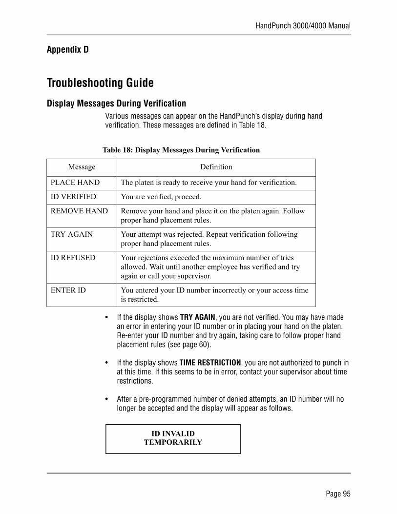
HandPunch 3000/4000 Manual
Appendix D
Troubleshooting Guide
Display Messages During VerificationVarious messages can appear on the HandPunch’s display during hand verification. These messages are defined in Table 18.
• If the display shows TRY AGAIN, you are not verified. You may have made an error in entering your ID number or in placing your hand on the platen. Re-enter your ID number and try again, taking care to follow proper hand placement rules (see page 60).
• If the display shows TIME RESTRICTION, you are not authorized to punch in at this time. If this seems to be in error, contact your supervisor about time restrictions.
• After a pre-programmed number of denied attempts, an ID number will no longer be accepted and the display will appear as follows.
Table 18: Display Messages During Verification
Message Definition
PLACE HAND The platen is ready to receive your hand for verification.
ID VERIFIED You are verified, proceed.
REMOVE HAND Remove your hand and place it on the platen again. Follow proper hand placement rules.
TRY AGAIN Your attempt was rejected. Repeat verification following proper hand placement rules.
ID REFUSED Your rejections exceeded the maximum number of tries allowed. Wait until another employee has verified and try again or call your supervisor.
ENTER ID You entered your ID number incorrectly or your access time is restricted.
ID INVALIDTEMPORARILY
Page 95
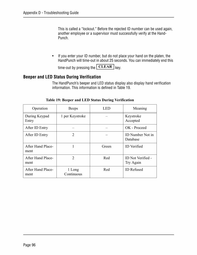
Appendix D - Troubleshooting Guide
This is called a “lockout.” Before the rejected ID number can be used again, another employee or a supervisor must successfully verify at the Hand-Punch.
• If you enter your ID number, but do not place your hand on the platen, the HandPunch will time-out in about 25 seconds. You can immediately end this
time-out by pressing the key.
Beeper and LED Status During VerificationThe HandPunch’s beeper and LED status display also display hand verification information. This information is defined in Table 19.
CLEAR
Table 19: Beeper and LED Status During Verification
Operation Beeps LED Meaning
During Keypad Entry
1 per Keystroke – Keystroke Accepted
After ID Entry – – OK - Proceed
After ID Entry 2 – ID Number Not in Database
After Hand Place-ment
1 Green ID Verified
After Hand Place-ment
2 Red ID Not Verified - Try Again
After Hand Place-ment
1 Long Continuous
Red ID Refused
Page 96
HandPunch 3000/4000 Manual
GlossaryAddress, IP – An Internet Protocol address is a unique address assigned to a computer
for communicating over a LAN/WAN. It is made up of 4 sets of numbers, separated by periods (for example, 123.245.78.901).
Address, HandPunch – A HandPunch Address is a unique identification number assigned to a HandPunch. Each HandPunch on a site must be assigned it’s own unique address.
AWG – American Wire Gauge is a U.S. standard set of wire conductor sizes. The “gauge” refers to the diameter of the wire. The higher the gauge number, the smaller the diameter, the thinner the wire, and the greater the electrical resistance. Thicker, smaller gauge wire carries more current because it has less electrical resistance over a given length. Thicker wire is better for long wire distances.
Daisy-Chain – A Daisy-Chain is a method of wiring together HandPunch on a network, where the first HandPunch is connected to the second HandPunch, which is connected to the third HandPunch, and so on until the last HandPunch is reached.
End-of-Line (EOL) Termination – EOL Termination is a set of resistors attached to the data lines at the last HandPunch physically connected to a network. These resistors prevent data signal distortion and reflection back across the data lines, improving the integrity of the network connection.
HandPunch Address – see Address, HandPunch
IP Address – see Address, IP
Platen – The Platen is the flat surface at the base of the HandPunch, on which a user places his/her hand for enrollment and verification. The platen has guide pins to ensure the user’s fingers are consistently positioned correctly.
Template – A Template is a set of data generated for a user. It is made up of the user’s enrollment information and any system configuration parameters that are assigned to the user. The template is stored at each HandPunch and can be stored at the host computer with the Time and Attendance software.
Time Zone – A Time Zone is an identified period of time, during which a user is allowed to punch in or out at a HandPunch. Punch attempts outside of that time period are rejected by the HandPunch.
Transaction – A Transaction is any kind of event recorded at a HandPunch. Transactions may include In or Out punches, department transfers, and supervisor edits.
Page 97

Glossary
Wiegand™ Reader – The term “Wiegand Reader” has two meanings depending upon its application. A true Wiegand reader reads a specially constructed card made up of small pieces of magnetic wire. As the card is swiped through the reader, the individual bits of wire generate a unique data signal. This data signal is made up of a Facility Code field (typically 8 bits), an ID Number field (typically 16 bits), and parity bits (typically 2 bits) for a total of 26 bits of data. Now this 26-bit Wiegand data format has been adopted by a variety of card reader devices for entering user ID data. Other Wiegand formats (for example, 37-bit) are used as well.
Page 98

HandPunch 3000/4000 Manual
Limited Warranty
Recognition Systems, Inc. (the “Company”) warrants to the original user the products manufactured by the Company (the “Product”) to be free of defects in material and workmanship for a period of one year from the date of purchase by such user or 15 months from the date of shipment from the factory, whichever is sooner, provided:
1. The Company has been notified within such period by return of any alleged defective product, free and clear of all liens and encumbrances, to the Com-pany or its authorized dealer, transportation prepaid; and
2. The Product has not been abused, misused, or improperly maintained and/or repaired during such period; and
3. Such defect has not been caused by ordinary wear and tear; and
4. Such defect is not the result of voltage surges/brownouts, lightning, water damage/flooding, fire, explosion, earthquakes, tornadoes, acts of aggression/war, or similar phenomenon; and
5. Accessories used as integral to the Product have been approved by the Company.
The Company shall, at its option, either repair or replace, free of charge, the Product found, upon the Company’s inspection, to be so defective, or if agreed upon, refund the purchase price, less a reasonable allowance for depreciation, in exchange for the Product.
THE COMPANY MAKES NO OTHER WARRANTY AND ALL IMPLIED WARRANTIES INCLUDING ANY WARRANTY OF MERCHANTABILITY OR FITNESS FOR A PARTICULAR PURPOSE ARE LIMITED TO THE DURATION OF THE EXPRESSED WARRANTY PERIOD AS SET FORTH ABOVE.
THE COMPANY’S MAXIMUM LIABILITY THEREUNDER IS LIMITED TO THE PURCHASE PRICE OF THE PRODUCT. IN NO EVENT SHALL THE COMPANY BE LIABLE FOR ANY CONSEQUENTIAL, INDIRECT, INCIDENTAL, OR SPECIAL DAMAGES OF ANY NATURE ARISING FROM THE SAME OR THE USE OF THE PRODUCT.
Recognition Systems Inc. reserves the right to make changes in the design of any of its products without incurring any obligation to make the same change on units previously purchased.
Page 99

Warranty
This page is intentionally left blank.
Page 100