Embed Size (px)
Citation preview
Graco Inc. P.O. Box 1441 Minneapolis, MN 55440-1441Copyright 2003, Graco Inc. is registered to I.S. EN ISO 9001
309577H
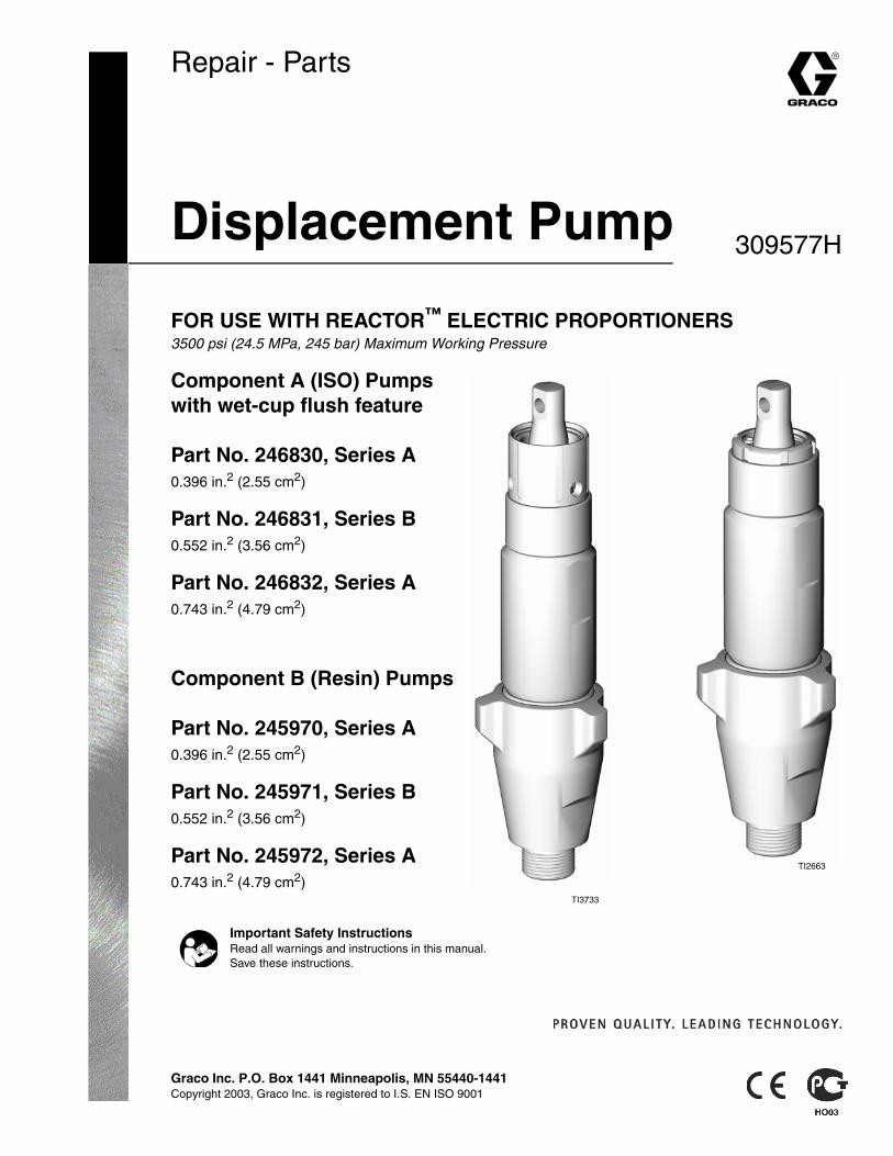
Repair - Parts
Displacement Pump
FOR USE WITH REACTOR™ ELECTRIC PROPORTIONERS3500 psi (24.5 MPa, 245 bar) Maximum Working Pressure
Component A (ISO) Pumps with wet-cup flush feature
Part No. 246830, Series A0.396 in.2 (2.55 cm2)
Part No. 246831, Series B0.552 in.2 (3.56 cm2)
Part No. 246832, Series A0.743 in.2 (4.79 cm2)
Component B (Resin) Pumps
Part No. 245970, Series A0.396 in.2 (2.55 cm2)
Part No. 245971, Series B0.552 in.2 (3.56 cm2)
Part No. 245972, Series A0.743 in.2 (4.79 cm2)
Important Safety InstructionsRead all warnings and instructions in this manual. Save these instructions.
TI2663
TI3733
Manual Conventions
2 309577H
ContentsManual Conventions . . . . . . . . . . . . . . . . . . . . . . . . 2Related Manuals . . . . . . . . . . . . . . . . . . . . . . . . . . . 2Warning . . . . . . . . . . . . . . . . . . . . . . . . . . . . . . . . . . . 3Pressure Relief Procedure . . . . . . . . . . . . . . . . . . . 5Tools Needed . . . . . . . . . . . . . . . . . . . . . . . . . . . . . . 6Repair Kits . . . . . . . . . . . . . . . . . . . . . . . . . . . . . . . . 6Clean and Inspect Parts . . . . . . . . . . . . . . . . . . . . . 6Supply Wet-cups with Throat Seal Liquid . . . . . . . 7
Cutaway Views . . . . . . . . . . . . . . . . . . . . . . . . . . . . . 8Disassembly . . . . . . . . . . . . . . . . . . . . . . . . . . . . . . 10Reassembly . . . . . . . . . . . . . . . . . . . . . . . . . . . . . . 15Parts . . . . . . . . . . . . . . . . . . . . . . . . . . . . . . . . . . . . 22Accessories . . . . . . . . . . . . . . . . . . . . . . . . . . . . . . 26Technical Data . . . . . . . . . . . . . . . . . . . . . . . . . . . . 27Graco Standard Warranty . . . . . . . . . . . . . . . . . . . 28Graco Information . . . . . . . . . . . . . . . . . . . . . . . . . 28
Manual ConventionsWarning
Caution
Note
Related ManualsThe following manuals are available for the Reactor™. Refer to these manuals for detailed equipment informa-tion.
WARNING
A warning alerts you to possible serious injury or death if you do not follow instructions.
Symbols, such as fluid injection (shown), alert you to a specific hazard and direct you to read the indicated hazard warnings on pages 3-4.
CAUTION
A caution alerts you to possible equipment damage or destruction if you do not follow instructions.
A note indicates additional helpful information.
Reactor Electric Proportioner
Part No. Description
309551 or 312065
Reactor Electric Proportioner, Operation Manual (English)
309574 or 312066
Reactor Electric Proportioner, Repair-Parts Manual (English)
309911 Reactor Pump Wet-Cup Flush Kits
Warning
309577H 3
WARNINGSKIN INJECTION HAZARDHigh-pressure fluid from gun, hose leaks, or ruptured components will pierce skin. This may look like just a cut, but it is a serious injury that can result in amputation. Get immediate surgical treatment.
• Do not point the gun at anyone or at any part of the body.
• Do not put your hand or fingers over the gun fluid nozzle.
• Do not stop or deflect leaks with your hand, body, glove, or rag.
• Do not “blow back” fluid; this is not an air spray system.
• Follow Pressure Relief Procedure, page 5, when you stop spraying and before cleaning, check-ing, or servicing equipment.
• Use lowest possible pressure when flushing, priming, or troubleshooting.
• Engage spray gun piston safety lock when not spraying.
• Tighten all fluid connections before operating the equipment.
• Check hoses, tubes, and couplings daily. Replace worn or damaged parts immediately. High pres-sure hose cannot be recoupled; replace the entire hose.
FIRE AND EXPLOSION HAZARDSolvent and fumes in work area can ignite or explode. To help prevent fire and explosion:
• Use equipment only in well ventilated area.
• Eliminate all ignition sources, such as pilot lights, cigarettes and plastic drop cloths (potential static arc).
• Do not plug or unplug power cords or turn lights on or off when flammable fumes are present.
• Keep the work area free of debris, including solvent, rags, and gasoline.
• Ground equipment and conductive objects. See Grounding in your Reactor manual.
• Hold gun firmly to side of grounded pail when triggering into pail.
• Use only grounded hoses.
• If there is static sparking or you feel a shock, stop operation immediately. Do not use equipment until you identify and correct the problem.
EQUIPMENT MISUSE HAZARDMisuse can cause serious injury or death.
• For professional use only.
• Use equipment only for its intended purpose. Call your Graco distributor for information.
• Read manuals, warnings, tags, and labels before operating equipment. Follow instructions.
• Check equipment daily. Repair or replace worn or damaged parts immediately.
• Do not alter or modify equipment. Use only Graco parts and accessories.
• Do not exceed the maximum working pressure or temperature rating of the lowest rated system component. See Technical Data in all equipment manuals.
• Use fluids and solvents that are compatible with equipment wetted parts. See Technical Data in all equipment manuals. Read fluid and solvent manufacturer’s warnings.
• Route hoses and cables away from traffic areas, sharp edges, moving parts, and hot surfaces.
• Do not use hoses to pull equipment.
• Comply with all applicable safety regulations.
Warning
4 309577H
BURN HAZARDThis equipment is used with heated fluid, which can cause equipment surfaces to become very hot. To avoid severe burns: • Do not touch hot fluid or equipment.
• Allow equipment to cool completely before touching it.
• Wear gloves if fluid temperature exceeds 110°F (43°C).
TOXIC FLUID OR FUMES HAZARDToxic fluids or fumes can cause serious injury or death if splashed in the eyes or on skin, inhaled, or swallowed.
• Read Material Safety Data Sheet (MSDS) to know the specific hazards of the fluids you are using.
• Store hazardous fluid in approved containers, and dispose of it according to applicable guidelines.
PERSONAL PROTECTIVE EQUIPMENTYou must wear proper protective equipment when operating, servicing, or when in the operating area of the equipment to help protect you from serious injury, including eye injury; inhalation of toxic fumes; and hearing loss. This equipment includes but is not limited to:
• Protective eyewear
• Gloves, clothing, and respirator as recommended by the fluid and solvent manufacturer
• Hearing protection.
WARNING
Pressure Relief Procedure
309577H 5
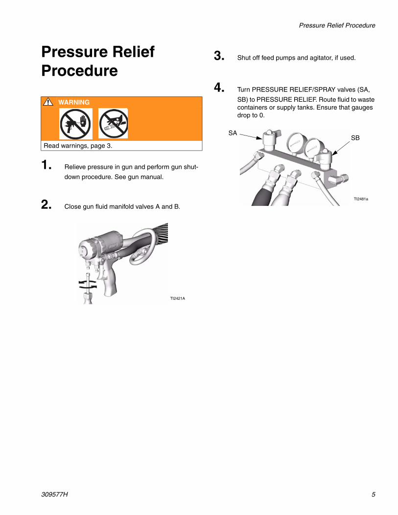
Pressure Relief Procedure
WARNING
Read warnings, page 3.
1. Relieve pressure in gun and perform gun shut-
down procedure. See gun manual.
2. Close gun fluid manifold valves A and B.
TI2421A
3. Shut off feed pumps and agitator, if used.
4. Turn PRESSURE RELIEF/SPRAY valves (SA,
SB) to PRESSURE RELIEF. Route fluid to waste containers or supply tanks. Ensure that gauges drop to 0.
TI2481a
SASB
Tools Needed
6 309577H
Tools Needed• Vise with flat jaws
• 12 in. adjustable, open end wrench (2)
• Non-sparking hammer, 20 oz maximum
• Small screwdriver
• Throat Seal Liquid (TSL), Graco Part No. 206995
• ISO Pump Oil, Graco Part No. 217374
• Pick or long small screwdriver
• Snap-ring pliers
• 1/2 in. (13 mm) diameter plastic rod
• 7/8 in. deep-well socket (246830 and 245970 only)
• 1/2 in. (13 mm) x 2.5 in. (64 mm) bolt with washers and nut
• Channel locks
• Dropcloth and rags
Repair KitsA repair kit is available for your pump. Kit parts are marked with an asterisk, for example (3*). See page 23. Kit must be purchased separately. For best results, use all parts in the kit.
Clean and Inspect Parts
1. Clean and inspect all parts. Intake and piston
ball seats, sleeve, and displacement rod must not be worn, scratched, or damaged.
2. Remove and clean sleeve when repacking
pump.

Supply Wet-cups with Throat Seal Liquid
309577H 7
Supply Wet-cups with Throat Seal Liquid
WARNING
Pump rod and connecting rod move during operation. Moving parts can cause serious injury such as pinch-ing or amputation. Keep hands and fingers away from wet-cup during operation. Turn main power OFF
before filling wet cup.
1. Component A (ISO) Pump: Keep reservoir (R)
3/4 filled with Graco Throat Seal Liquid (TSL), Part No. 206995. Wet-cup piston (28) circulates TSL through packing nut/wet-cup (19), to carry away isocyanate film on displacement rod.
After some time TSL will thicken and darken, and must be replaced. Thick, dirty TSL will not pump through lines and will harden in wet-cup. Check condition of TSL every week, minimum, and change when needed.
R
TI3765a-2
2. Component B (Resin) Pump: Check felt wash-
ers (21) in packing nut/wet-cup (19) daily. Keep saturated with Graco Throat Seal Liquid (TSL), Part No. 206995, to prevent material from hard-ening on displacement rod. Replace felt wash-ers when worn or contaminated with hardened material.
19
TI3765a-1
Cutaway Views
8 309577H
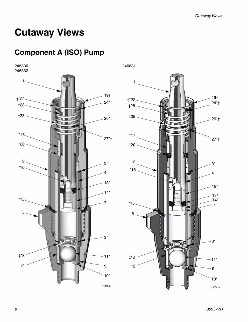
Cutaway Views
Component A (ISO) Pump
1
19††*22
†25
24*†
*17
*20
2
*16
*15
5
3*
4
14*
7
13*
3*
11*
9
10*
‡*8
12
TI3734b
26*†
27*†
†28
246830246832
1
19††*22
†25
24*†
*17
*20
2
*16
*15
5
3*
4
13*
7
18*
3*
11*
9
10*
‡*8
12
TI3734C
26*†
27*†
†28
14*
246831
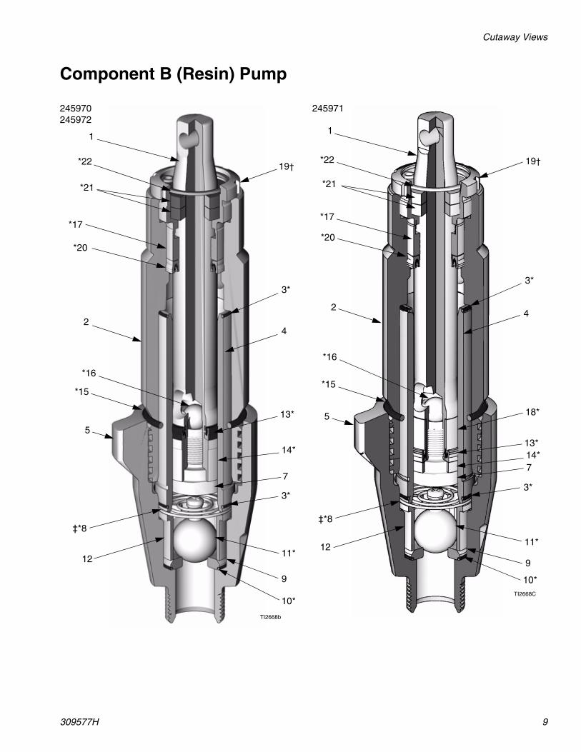
Cutaway Views
309577H 9
Component B (Resin) Pump
1
19†*22
*21
*17
*20
2
*16
*15
5
3*
4
14*
7
13*
3*
11*
9
10*
‡*8
12
TI2668b
245970245972
1
19†*22
*21
*17
*20
2
*16
*15
5
3*
4
14*7
13*
3*
11*
9
10*
‡*8
12
TI2668C
18*
245971
Disassembly
10 309577H
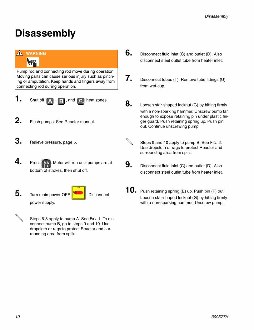
Disassembly
WARNING
Pump rod and connecting rod move during operation. Moving parts can cause serious injury such as pinch-ing or amputation. Keep hands and fingers away from connecting rod during operation.
1. Shut off , , and heat zones.
2. Flush pumps. See Reactor manual.
3. Relieve pressure, page 5.
4. Press . Motor will run until pumps are at
bottom of strokes, then shut off.
5. Turn main power OFF . Disconnect
power supply.
Steps 6-8 apply to pump A. See FIG. 1. To dis-connect pump B, go to steps 9 and 10. Use dropcloth or rags to protect Reactor and sur-rounding area from spills.
A B
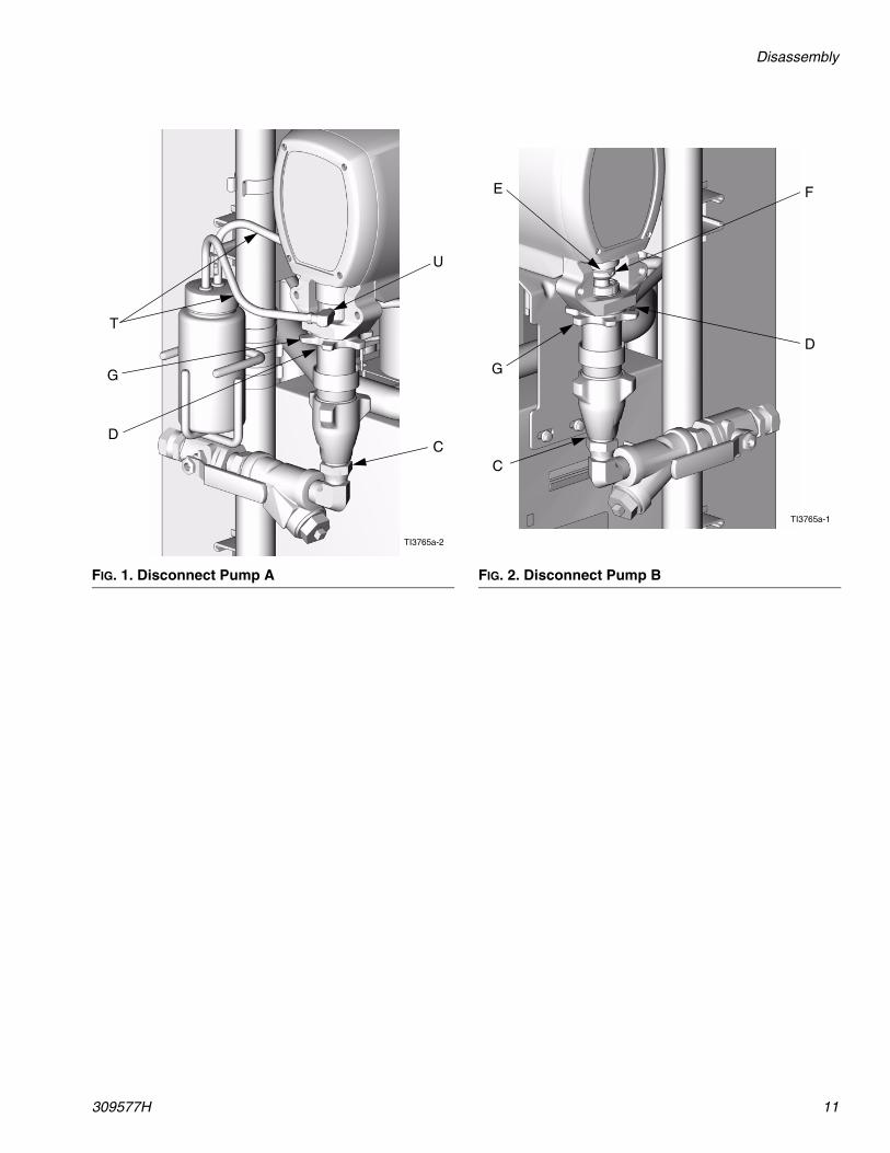
6. Disconnect fluid inlet (C) and outlet (D). Also
disconnect steel outlet tube from heater inlet.
7. Disconnect tubes (T). Remove tube fittings (U)
from wet-cup.
8. Loosen star-shaped locknut (G) by hitting firmly
with a non-sparking hammer. Unscrew pump far enough to expose retaining pin under plastic fin-ger guard. Push retaining spring up. Push pin out. Continue unscrewing pump.
Steps 9 and 10 apply to pump B. See FIG. 2. Use dropcloth or rags to protect Reactor and surrounding area from spills.
9. Disconnect fluid inlet (C) and outlet (D). Also
disconnect steel outlet tube from heater inlet.
10. Push retaining spring (E) up. Push pin (F) out.
Loosen star-shaped locknut (G) by hitting firmly with a non-sparking hammer. Unscrew pump.
Disassembly
309577H 11
FIG. 1. Disconnect Pump A
TI3765a-2
C
U
G
D
T
FIG. 2. Disconnect Pump B
TI3765a-1
C
F
G
D
E
Disassembly
12 309577H
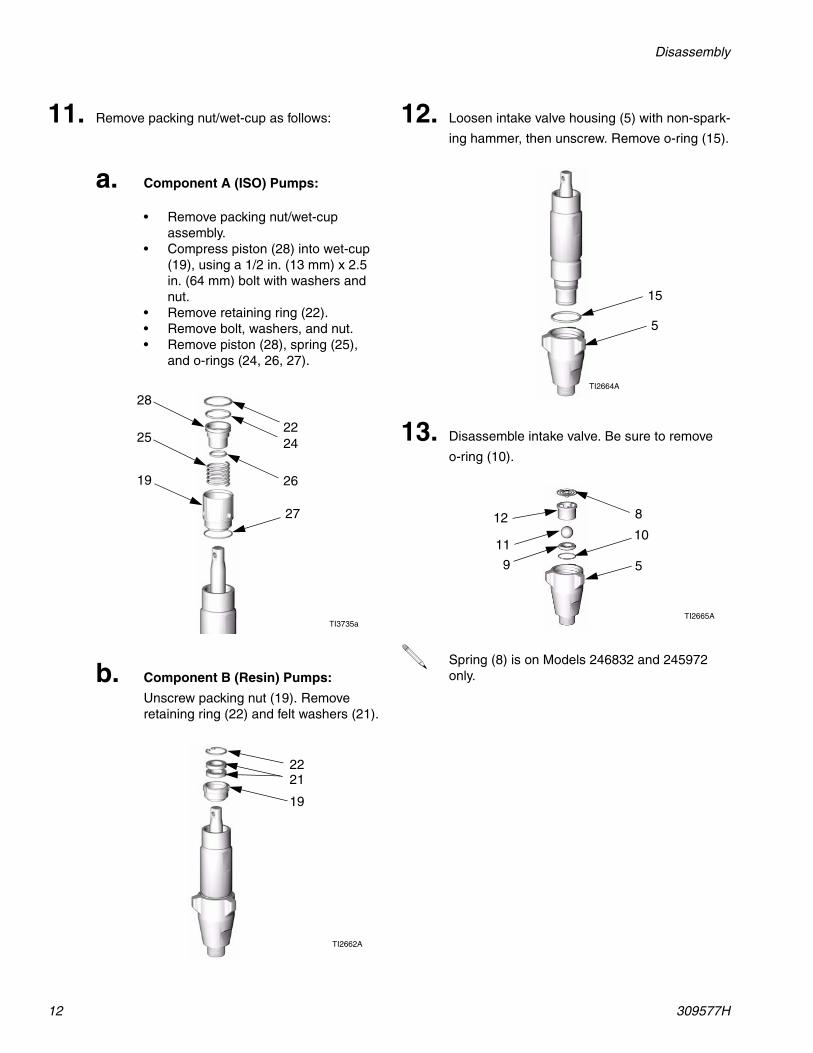
11. Remove packing nut/wet-cup as follows:
a. Component A (ISO) Pumps:
• Remove packing nut/wet-cup assembly.
• Compress piston (28) into wet-cup (19), using a 1/2 in. (13 mm) x 2.5 in. (64 mm) bolt with washers and nut.
• Remove retaining ring (22).• Remove bolt, washers, and nut.• Remove piston (28), spring (25),
and o-rings (24, 26, 27).
b. Component B (Resin) Pumps:
Unscrew packing nut (19). Remove retaining ring (22) and felt washers (21).
TI3735a
19
25
28
2422
26
27
TI2662A
19
2221
12. Loosen intake valve housing (5) with non-spark-
ing hammer, then unscrew. Remove o-ring (15).
13. Disassemble intake valve. Be sure to remove
o-ring (10).
Spring (8) is on Models 246832 and 245972 only.
TI2664A
15
5
TI2665A
5
11
9
10
812
Disassembly
309577H 13
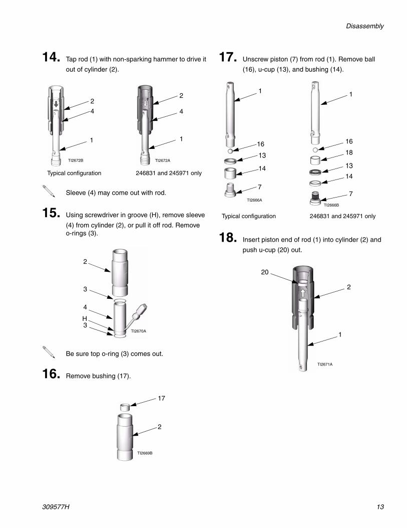
14. Tap rod (1) with non-sparking hammer to drive it
out of cylinder (2).
Sleeve (4) may come out with rod.
15. Using screwdriver in groove (H), remove sleeve
(4) from cylinder (2), or pull it off rod. Remove o-rings (3).
Be sure top o-ring (3) comes out.
16. Remove bushing (17).
TI2672A
1
2
4
TI2672B
1
2
4
246831 and 245971 onlyTypical configuration
TI2670A
2
3
4
H3
TI2669B
17
2
17. Unscrew piston (7) from rod (1). Remove ball
(16), u-cup (13), and bushing (14).
18. Insert piston end of rod (1) into cylinder (2) and
push u-cup (20) out.
TI2666A
1
16
13
7
14
1
16
18
13
7
14
TI2666B
246831 and 245971 onlyTypical configuration
TI2671A
1
2
20

Disassembly
14 309577H
Reassembly
309577H 15
Reassembly
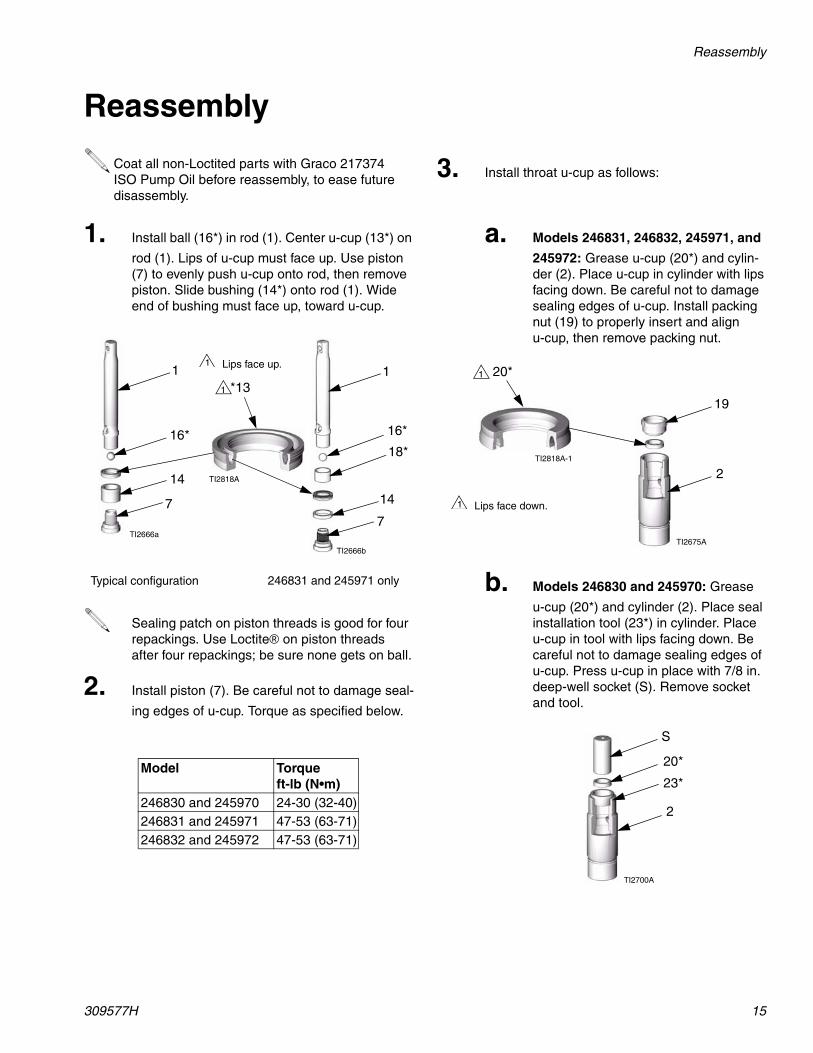
Coat all non-Loctited parts with Graco 217374 ISO Pump Oil before reassembly, to ease future disassembly.
1. Install ball (16*) in rod (1). Center u-cup (13*) on
rod (1). Lips of u-cup must face up. Use piston (7) to evenly push u-cup onto rod, then remove piston. Slide bushing (14*) onto rod (1). Wide end of bushing must face up, toward u-cup.
Sealing patch on piston threads is good for four repackings. Use Loctite® on piston threads after four repackings; be sure none gets on ball.
2. Install piston (7). Be careful not to damage seal-
ing edges of u-cup. Torque as specified below.
Model Torque ft-lb (N•m)
246830 and 245970 24-30 (32-40)246831 and 245971 47-53 (63-71)246832 and 245972 47-53 (63-71)
TI2666b
1
16*
18*
*13
7
TI2818A
1
Lips face up.1
14
246831 and 245971 onlyTypical configuration
1
16*
7
14
TI2666a
3. Install throat u-cup as follows:
a. Models 246831, 246832, 245971, and
245972: Grease u-cup (20*) and cylin-der (2). Place u-cup in cylinder with lips facing down. Be careful not to damage sealing edges of u-cup. Install packing nut (19) to properly insert and align u-cup, then remove packing nut.
b. Models 246830 and 245970: Grease
u-cup (20*) and cylinder (2). Place seal installation tool (23*) in cylinder. Place u-cup in tool with lips facing down. Be careful not to damage sealing edges of u-cup. Press u-cup in place with 7/8 in. deep-well socket (S). Remove socket and tool.
TI2675A
19
20*
2TI2818A-1
1
Lips face down.1
TI2700A
23*
20*
2
S
Reassembly
16 309577H
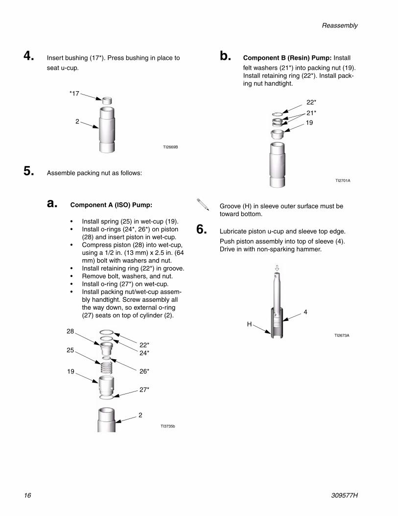
4. Insert bushing (17*). Press bushing in place to
seat u-cup.
5. Assemble packing nut as follows:
a. Component A (ISO) Pump:
• Install spring (25) in wet-cup (19). • Install o-rings (24*, 26*) on piston
(28) and insert piston in wet-cup. • Compress piston (28) into wet-cup,
using a 1/2 in. (13 mm) x 2.5 in. (64 mm) bolt with washers and nut.
• Install retaining ring (22*) in groove.• Remove bolt, washers, and nut.• Install o-ring (27*) on wet-cup. • Install packing nut/wet-cup assem-
bly handtight. Screw assembly all the way down, so external o-ring (27) seats on top of cylinder (2).
TI2669B
*17
2
TI3735b
19
25
28
24*22*
26*
27*
2
b. Component B (Resin) Pump: Install
felt washers (21*) into packing nut (19). Install retaining ring (22*). Install pack-ing nut handtight.
Groove (H) in sleeve outer surface must be toward bottom.
6. Lubricate piston u-cup and sleeve top edge.
Push piston assembly into top of sleeve (4). Drive in with non-sparking hammer.
TI2701A
22*
21*
19
TI2673A
H
4
Reassembly
309577H 17
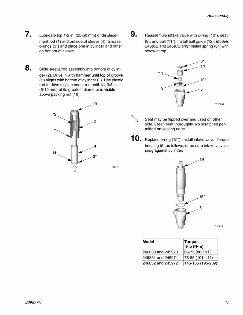
7. Lubricate top 1-2 in. (25-50 mm) of displace-
ment rod (1) and outside of sleeve (4). Grease o-rings (3*) and place one in cylinder and other on bottom of sleeve.
8. Slide sleeve/rod assembly into bottom of cylin-
der (2). Drive in with hammer until top of groove (H) aligns with bottom of cylinder (L). Use plastic rod to drive displacement rod until 1/4-3/8 in. (6-10 mm) of its greatest diameter is visible above packing nut (19).
TI2674A
19
*3
2
L
4
3*H
9. Reassemble intake valve with o-ring (10*), seat
(9), and ball (11*). Install ball guide (12). Models 246832 and 245972 only: Install spring (8*) with screw at top.
Seat may be flipped over and used on other side. Clean seat thoroughly. No scratches per-mitted on sealing edge.
10. Replace o-ring (15*). Install intake valve. Torque
housing (5) as follows, or be sure intake valve is snug against cylinder.
Model Torque ft-lb (N•m)
246830 and 245970 65-75 (88-101)246831 and 245971 75-85 (101-114)246832 and 245972 145-155 (195-209)
TI2665A
5
*11
9
10*
8*12
TI2687A
15*
19
5
Reassembly
18 309577H
a. Pump A: Wrap base of wet-cup (19)
with a rag and tighten securely with channel locks.
b. Pump B: Torque packing nut (19) to
90-110 in-lb (10-12 N•m).
11. Tighten packing nut/wet-cup.
Do not overtighten packing nut/wet-cup. Throat u-cup (20) is not adjustable.
WARNING
Pump rod and connecting rod move during operation. Moving parts can cause serious injury such as pinch-ing or amputation. Keep hands and fingers away from connecting rod during operation.
12. Reconnect power supply. Turn main power ON
.
13. Press . Motor will run until pumps are at
bottom of strokes, then shut off.
14. Turn main power OFF . Disconnect
power supply.
Steps 15-18 apply to pump B. See FIG. 3. To reconnect pump A, go to step 19.
15. Ensure star-shaped locknut (G) is screwed on
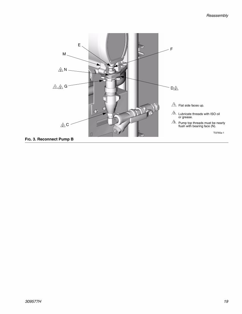
pump with flat side up. Screw pump into bearing housing (M) until pin holes align. Push pin (F) in. Pull retaining spring (E) down.
16. Continue screwing pump into housing until fluid
outlet (D) is aligned with steel tube and top threads are +/- 1/16 in. (2 mm) of bearing face (N).
17. Tighten star-shaped locknut (G) by hitting firmly
with a non-sparking hammer.
18. Reconnect fluid inlet (C) and outlet (D).
Reassembly
309577H 19
FIG. 3. Reconnect Pump B
C
D
FE
G
M
N
1
TI3765a-1
Flat side faces up.1
Lubricate threads with ISO oil or grease.
2
2 2
2
3
Pump top threads must be nearly flush with bearing face (N).
3
Reassembly
20 309577H
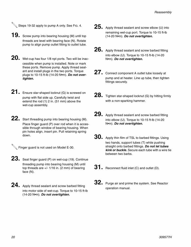
Steps 19-32 apply to pump A only. See FIG. 4.
19. Screw pump into bearing housing (M) until top
threads are level with bearing face (N). Rotate pump to align pump outlet fitting to outlet tube.
20. Wet-cup has four 1/8 npt ports. Two will be inac-
cessible when pump is installed. Note or mark these ports. Remove pump. Apply thread seal-ant and install plugs in the two ports. Torque plugs to 10-15 ft-lb (14-20 N•m). Do not over-tighten.
21. Ensure star-shaped locknut (G) is screwed on
pump with flat side up. Carefully twist and extend the rod (1) 2 in. (51 mm) above the wet-cup assembly.
22. Start threading pump into bearing housing (M).
Place finger guard (P) over rod when it is acces-sible through window of bearing housing. When pin holes align, insert pin. Pull retaining spring down.
Finger guard is not used on Model E-30.
23. Seat finger guard (P) on wet-cup (19). Continue
threading pump into bearing housing (M) until top threads are +/- 1/16 in. (2 mm) of bearing face (N).
24. Apply thread sealant and screw barbed fitting
into motor side of wet-cup. Torque to 10-15 ft-lb (14-20 N•m). Do not overtighten.
25. Apply thread sealant and screw elbow (U) into
remaining wet-cup port. Torque to 10-15 ft-lb (14-20 N•m). Do not overtighten.
26. Apply thread sealant and screw barbed fitting
into elbow (U). Torque to 10-15 ft-lb (14-20 N•m). Do not overtighten.
27. Connect component A outlet tube loosely at
pump and at heater. Line up tube, then tighten fittings securely.
28. Tighten star-shaped locknut (G) by hitting firmly
with a non-sparking hammer.
29. Apply thread sealant and screw barbed fitting
into elbow (U). Torque to 10-15 ft-lb (14-20 N•m). Do not overtighten.
30. Apply thin film of TSL to barbed fittings. Using
two hands, support tubes (T) while pushing straight onto barbed fittings. Do not let tubes kink or buckle. Secure each tube with a wire tie between two barbs.
31. Reconnect fluid inlet (C) and outlet (D).
32. Purge air and prime the system. See Reactor
operation manual.
Reassembly
309577H 21
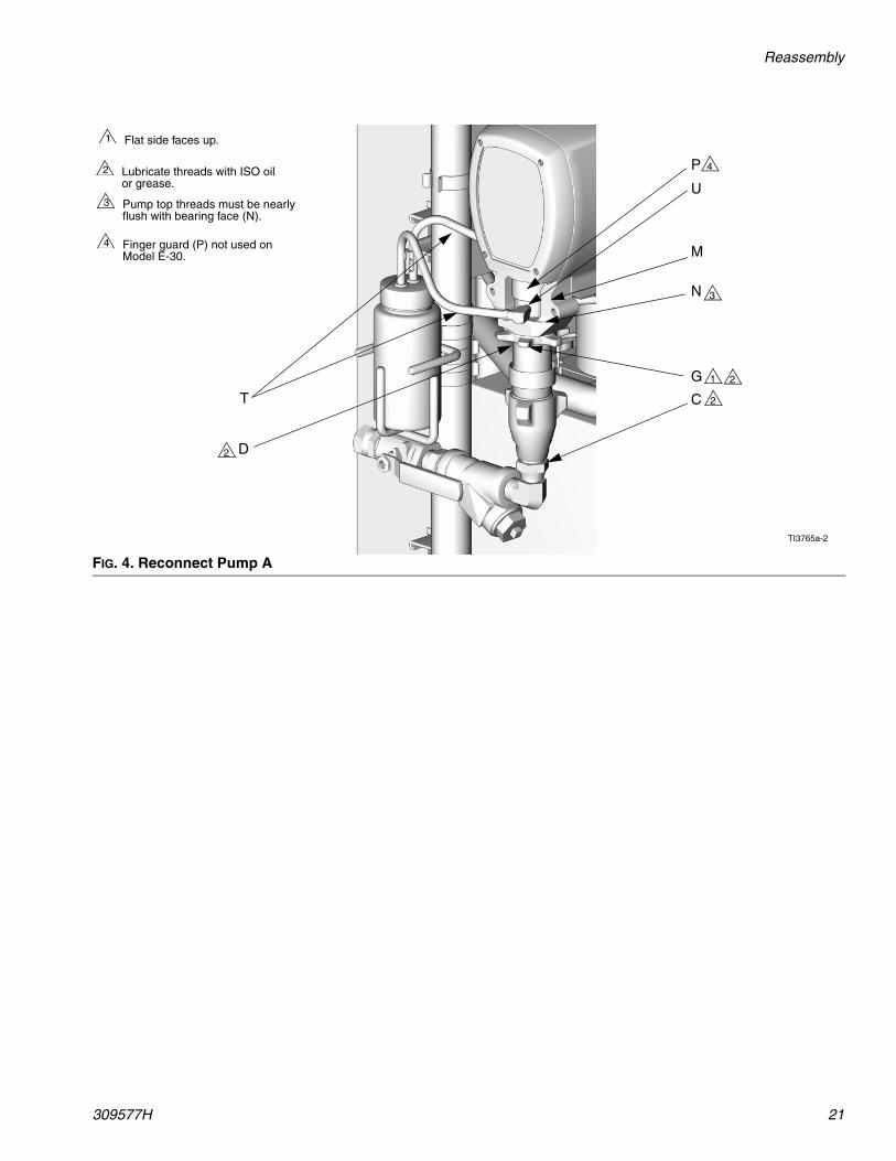
FIG. 4. Reconnect Pump A
C
D
T
G
M
N
1
TI3765a-2
Flat side faces up.1
Lubricate threads with ISO oil or grease.
2
2
2
2
3
Pump top threads must be nearly flush with bearing face (N).
3U
P
Finger guard (P) not used on Model E-30.
4
4
Parts
22 309577H
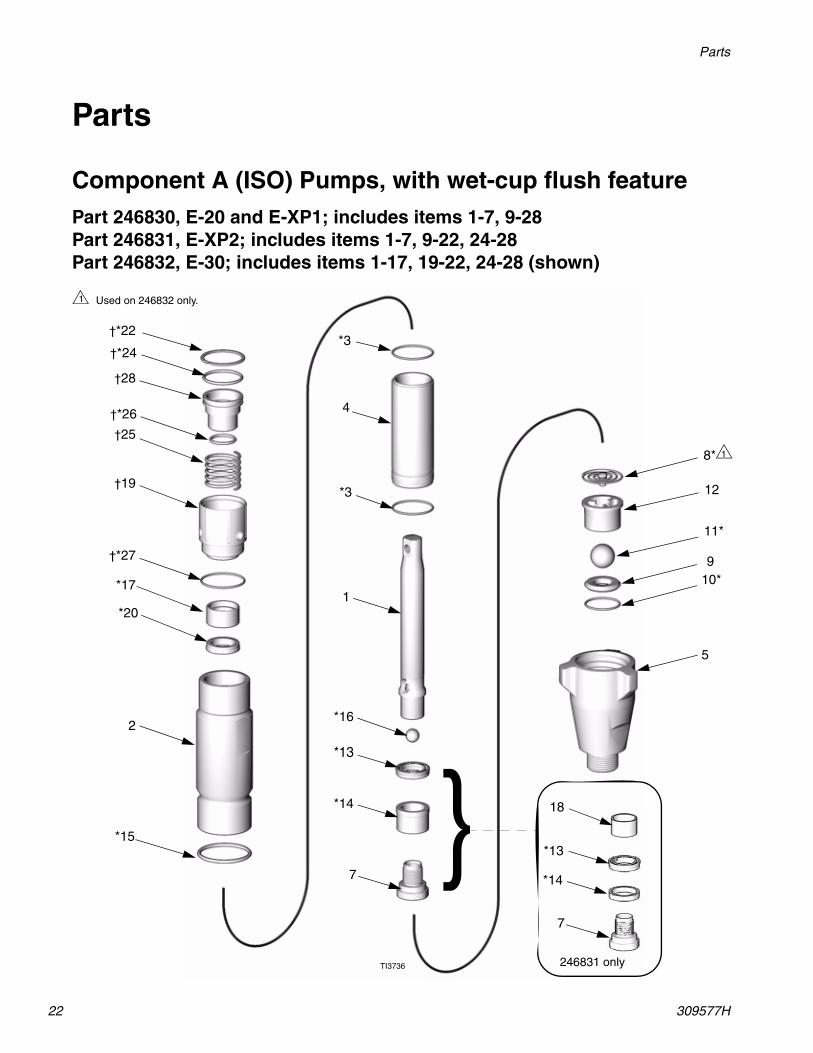
Parts
Component A (ISO) Pumps, with wet-cup flush featurePart 246830, E-20 and E-XP1; includes items 1-7, 9-28Part 246831, E-XP2; includes items 1-7, 9-22, 24-28Part 246832, E-30; includes items 1-17, 19-22, 24-28 (shown)
1
2
*3
*3
4
5
7
8*
10*9
11*
12
*15
*16
*17
†19
*20
†25
TI3736
Used on 246832 only.1
1
†28
†*24
†*22
†*26
†*27
*14
*13
18
*13
7
*14
}246831 only
Parts
309577H 23
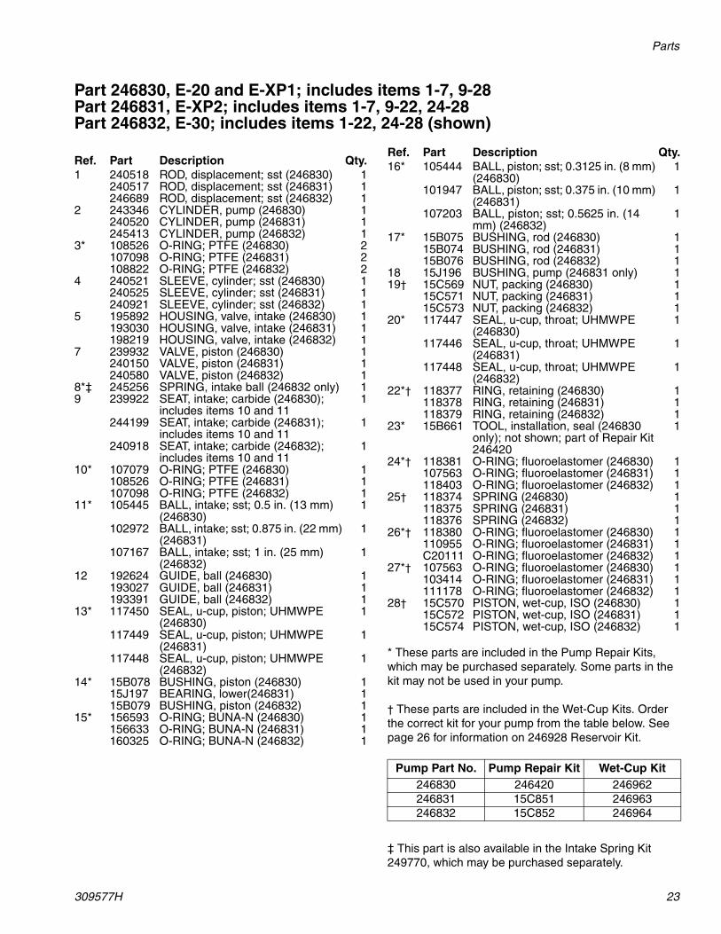
Part 246830, E-20 and E-XP1; includes items 1-7, 9-28Part 246831, E-XP2; includes items 1-7, 9-22, 24-28Part 246832, E-30; includes items 1-22, 24-28 (shown)
* These parts are included in the Pump Repair Kits, which may be purchased separately. Some parts in the kit may not be used in your pump.
† These parts are included in the Wet-Cup Kits. Order the correct kit for your pump from the table below. See page 26 for information on 246928 Reservoir Kit.
‡ This part is also available in the Intake Spring Kit 249770, which may be purchased separately.
Ref. Part Description Qty.1 240518 ROD, displacement; sst (246830) 1
240517 ROD, displacement; sst (246831) 1246689 ROD, displacement; sst (246832) 1
2 243346 CYLINDER, pump (246830) 1240520 CYLINDER, pump (246831) 1245413 CYLINDER, pump (246832) 1
3* 108526 O-RING; PTFE (246830) 2107098 O-RING; PTFE (246831) 2108822 O-RING; PTFE (246832) 2
4 240521 SLEEVE, cylinder; sst (246830) 1240525 SLEEVE, cylinder; sst (246831) 1240921 SLEEVE, cylinder; sst (246832) 1
5 195892 HOUSING, valve, intake (246830) 1193030 HOUSING, valve, intake (246831) 1198219 HOUSING, valve, intake (246832) 1
7 239932 VALVE, piston (246830) 1240150 VALVE, piston (246831) 1240580 VALVE, piston (246832) 1
8*‡ 245256 SPRING, intake ball (246832 only) 19 239922 SEAT, intake; carbide (246830);
includes items 10 and 111
244199 SEAT, intake; carbide (246831); includes items 10 and 11
1
240918 SEAT, intake; carbide (246832); includes items 10 and 11
1
10* 107079 O-RING; PTFE (246830) 1108526 O-RING; PTFE (246831) 1107098 O-RING; PTFE (246832) 1
11* 105445 BALL, intake; sst; 0.5 in. (13 mm) (246830)
1
102972 BALL, intake; sst; 0.875 in. (22 mm) (246831)
1
107167 BALL, intake; sst; 1 in. (25 mm) (246832)
1
12 192624 GUIDE, ball (246830) 1193027 GUIDE, ball (246831) 1193391 GUIDE, ball (246832) 1
13* 117450 SEAL, u-cup, piston; UHMWPE (246830)
1
117449 SEAL, u-cup, piston; UHMWPE (246831)
1
117448 SEAL, u-cup, piston; UHMWPE (246832)
1
14* 15B078 BUSHING, piston (246830) 115J197 BEARING, lower(246831) 115B079 BUSHING, piston (246832) 1
15* 156593 O-RING; BUNA-N (246830) 1156633 O-RING; BUNA-N (246831) 1160325 O-RING; BUNA-N (246832) 1
16* 105444 BALL, piston; sst; 0.3125 in. (8 mm) (246830)
1
101947 BALL, piston; sst; 0.375 in. (10 mm) (246831)
1
107203 BALL, piston; sst; 0.5625 in. (14 mm) (246832)
1
17* 15B075 BUSHING, rod (246830) 115B074 BUSHING, rod (246831) 115B076 BUSHING, rod (246832) 1
18 15J196 BUSHING, pump (246831 only) 119† 15C569 NUT, packing (246830) 1
15C571 NUT, packing (246831) 115C573 NUT, packing (246832) 1
20* 117447 SEAL, u-cup, throat; UHMWPE (246830)
1
117446 SEAL, u-cup, throat; UHMWPE (246831)
1
117448 SEAL, u-cup, throat; UHMWPE (246832)
1
22*† 118377 RING, retaining (246830) 1118378 RING, retaining (246831) 1118379 RING, retaining (246832) 1
23* 15B661 TOOL, installation, seal (246830 only); not shown; part of Repair Kit 246420
1
24*† 118381 O-RING; fluoroelastomer (246830) 1107563 O-RING; fluoroelastomer (246831) 1118403 O-RING; fluoroelastomer (246832) 1
25† 118374 SPRING (246830) 1118375 SPRING (246831) 1118376 SPRING (246832) 1
26*† 118380 O-RING; fluoroelastomer (246830) 1110955 O-RING; fluoroelastomer (246831) 1C20111 O-RING; fluoroelastomer (246832) 1
27*† 107563 O-RING; fluoroelastomer (246830) 1103414 O-RING; fluoroelastomer (246831) 1111178 O-RING; fluoroelastomer (246832) 1
28† 15C570 PISTON, wet-cup, ISO (246830) 115C572 PISTON, wet-cup, ISO (246831) 115C574 PISTON, wet-cup, ISO (246832) 1
Pump Part No. Pump Repair Kit Wet-Cup Kit246830 246420 246962246831 15C851 246963246832 15C852 246964
Ref. Part Description Qty.
Parts
24 309577H
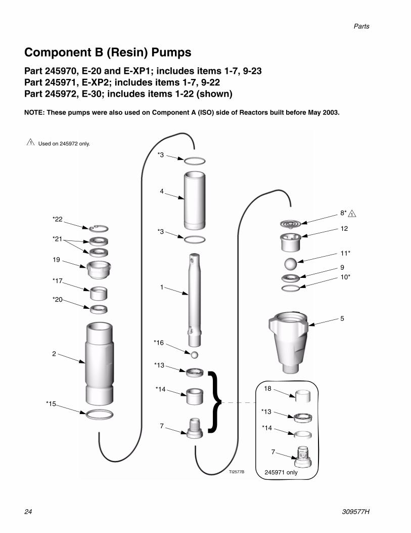
Component B (Resin) PumpsPart 245970, E-20 and E-XP1; includes items 1-7, 9-23Part 245971, E-XP2; includes items 1-7, 9-22Part 245972, E-30; includes items 1-22 (shown)
NOTE: These pumps were also used on Component A (ISO) side of Reactors built before May 2003.
*17
19
*20
*21
*22
TI2577B
Used on 245972 only.1
1
2
*3
*3
4
5
7
8*
10*9
11*
12
*13
*15
*16
1
*14 18
*13
7
*14
}245971 only
Parts
309577H 25
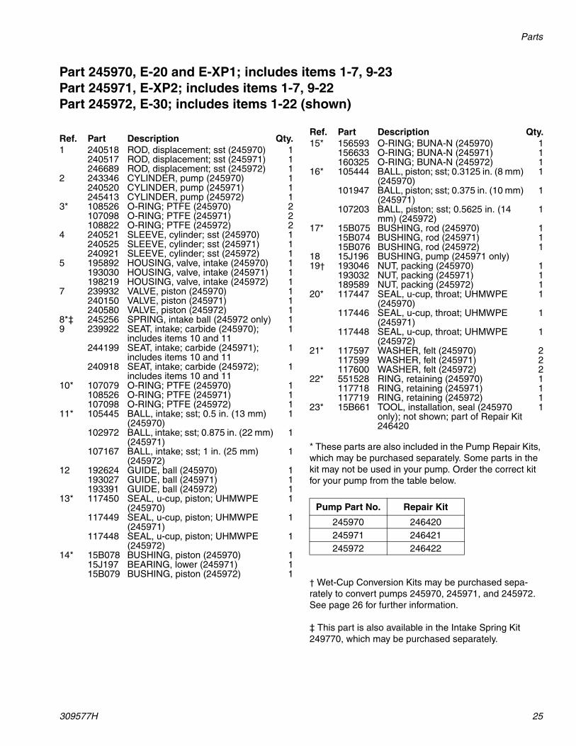
Part 245970, E-20 and E-XP1; includes items 1-7, 9-23Part 245971, E-XP2; includes items 1-7, 9-22Part 245972, E-30; includes items 1-22 (shown)
* These parts are also included in the Pump Repair Kits, which may be purchased separately. Some parts in the kit may not be used in your pump. Order the correct kit for your pump from the table below.
† Wet-Cup Conversion Kits may be purchased sepa-rately to convert pumps 245970, 245971, and 245972. See page 26 for further information.
‡ This part is also available in the Intake Spring Kit 249770, which may be purchased separately.
Ref. Part Description Qty.1 240518 ROD, displacement; sst (245970) 1
240517 ROD, displacement; sst (245971) 1246689 ROD, displacement; sst (245972) 1
2 243346 CYLINDER, pump (245970) 1240520 CYLINDER, pump (245971) 1245413 CYLINDER, pump (245972) 1
3* 108526 O-RING; PTFE (245970) 2107098 O-RING; PTFE (245971) 2108822 O-RING; PTFE (245972) 2
4 240521 SLEEVE, cylinder; sst (245970) 1240525 SLEEVE, cylinder; sst (245971) 1240921 SLEEVE, cylinder; sst (245972) 1
5 195892 HOUSING, valve, intake (245970) 1193030 HOUSING, valve, intake (245971) 1198219 HOUSING, valve, intake (245972) 1
7 239932 VALVE, piston (245970) 1240150 VALVE, piston (245971) 1240580 VALVE, piston (245972) 1
8*‡ 245256 SPRING, intake ball (245972 only) 19 239922 SEAT, intake; carbide (245970);
includes items 10 and 111
244199 SEAT, intake; carbide (245971); includes items 10 and 11
1
240918 SEAT, intake; carbide (245972); includes items 10 and 11
1
10* 107079 O-RING; PTFE (245970) 1108526 O-RING; PTFE (245971) 1107098 O-RING; PTFE (245972) 1
11* 105445 BALL, intake; sst; 0.5 in. (13 mm) (245970)
1
102972 BALL, intake; sst; 0.875 in. (22 mm) (245971)
1
107167 BALL, intake; sst; 1 in. (25 mm) (245972)
1
12 192624 GUIDE, ball (245970) 1193027 GUIDE, ball (245971) 1193391 GUIDE, ball (245972) 1
13* 117450 SEAL, u-cup, piston; UHMWPE (245970)
1
117449 SEAL, u-cup, piston; UHMWPE (245971)
1
117448 SEAL, u-cup, piston; UHMWPE (245972)
1
14* 15B078 BUSHING, piston (245970) 115J197 BEARING, lower (245971) 115B079 BUSHING, piston (245972) 1
15* 156593 O-RING; BUNA-N (245970) 1156633 O-RING; BUNA-N (245971) 1160325 O-RING; BUNA-N (245972) 1
16* 105444 BALL, piston; sst; 0.3125 in. (8 mm) (245970)
1
101947 BALL, piston; sst; 0.375 in. (10 mm) (245971)
1
107203 BALL, piston; sst; 0.5625 in. (14 mm) (245972)
1
17* 15B075 BUSHING, rod (245970) 115B074 BUSHING, rod (245971) 115B076 BUSHING, rod (245972) 1
18 15J196 BUSHING, pump (245971 only)19† 193046 NUT, packing (245970) 1
193032 NUT, packing (245971) 1189589 NUT, packing (245972) 1
20* 117447 SEAL, u-cup, throat; UHMWPE (245970)
1
117446 SEAL, u-cup, throat; UHMWPE (245971)
1
117448 SEAL, u-cup, throat; UHMWPE (245972)
1
21* 117597 WASHER, felt (245970) 2117599 WASHER, felt (245971) 2117600 WASHER, felt (245972) 2
22* 551528 RING, retaining (245970) 1117718 RING, retaining (245971) 1117719 RING, retaining (245972) 1
23* 15B661 TOOL, installation, seal (245970 only); not shown; part of Repair Kit 246420
1
Pump Part No. Repair Kit
245970 246420245971 246421245972 246422
Ref. Part Description Qty.
Accessories
26 309577H
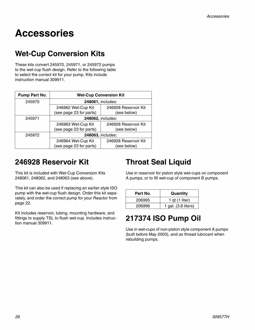
Accessories
Wet-Cup Conversion KitsThese kits convert 245970, 245971, or 245972 pumps to the wet-cup flush design. Refer to the following table to select the correct kit for your pump. Kits include instruction manual 309911.
246928 Reservoir KitThis kit is included with Wet-Cup Conversion Kits 248061, 248062, and 248063 (see above).
This kit can also be used if replacing an earlier style ISO pump with the wet-cup flush design. Order this kit sepa-rately, and order the correct pump for your Reactor from page 22.
Kit includes reservoir, tubing, mounting hardware, and fittings to supply TSL to flush wet-cup. Includes instruc-tion manual 309911.
Throat Seal LiquidUse in reservoir for piston style wet-cups on component A pumps, or to fill wet-cup of component B pumps.
217374 ISO Pump OilUse in wet-cups of non-piston style component A pumps (built before May 2003), and as thread lubricant when rebuilding pumps.
Pump Part No. Wet-Cup Conversion Kit
245970 248061, includes:246962 Wet-Cup Kit
(see page 23 for parts)246928 Reservoir Kit
(see below)245971 248062, includes:
246963 Wet-Cup Kit (see page 23 for parts)
246928 Reservoir Kit (see below)
245972 248063, includes:246964 Wet-Cup Kit
(see page 23 for parts)246928 Reservoir Kit
(see below)
Part No. Quantity
206995 1 qt (1 liter)206996 1 gal. (3.8 liters)
Technical Data
309577H 27
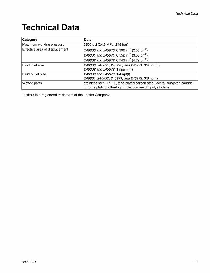
Technical Data
Loctite® is a registered trademark of the Loctite Company.
Category DataMaximum working pressure 3500 psi (24.5 MPa, 245 bar)Effective area of displacement 246830 and 245970: 0.396 in.2 (2.55 cm2)
246831 and 245971: 0.552 in.2 (3.56 cm2)
246832 and 245972: 0.743 in.2 (4.79 cm2)Fluid inlet size 246830, 246831, 245970, and 245971: 3/4 npt(m)
246832 and 245972: 1 npsm(m)Fluid outlet size 246830 and 245970: 1/4 npt(f)
246831, 246832, 245971, and 245972: 3/8 npt(f)Wetted parts stainless steel, PTFE, zinc-plated carbon steel, acetal, tungsten carbide,
chrome plating, ultra-high molecular weight polyethylene
All written and visual data contained in this document reflects the latest product information available at the time of publication. Graco reserves the right to make changes at any time without notice.
This manual contains English. MM 309577
Graco Headquarters: Minneapolis,International Offices: Belgium, China, Japan, Korea
GRACO INC. P.O. BOX 1441 MINNEAPOLIS, MN 55440-1441309577 2003 Revised 5/2008
Graco Standard WarrantyGraco warrants all equipment referenced in this document which is manufactured by Graco and bearing its name to be free from defects in material and workmanship on the date of sale to the original purchaser for use. With the exception of any special, extended, or limited warranty published by Graco, Graco will, for a period of twelve months from the date of sale, repair or replace any part of the equipment determined by Graco to be defective. This warranty applies only when the equipment is installed, operated and maintained in accordance with Graco’s written recommendations.
This warranty does not cover, and Graco shall not be liable for general wear and tear, or any malfunction, damage or wear caused by faulty installation, misapplication, abrasion, corrosion, inadequate or improper maintenance, negligence, accident, tampering, or substitution of non-Graco component parts. Nor shall Graco be liable for malfunction, damage or wear caused by the incompatibility of Graco equipment with structures, accessories, equipment or materials not supplied by Graco, or the improper design, manufacture, installation, operation or maintenance of structures, accessories, equipment or materials not supplied by Graco.
This warranty is conditioned upon the prepaid return of the equipment claimed to be defective to an authorized Graco distributor for verification of the claimed defect. If the claimed defect is verified, Graco will repair or replace free of charge any defective parts. The equipment will be returned to the original purchaser transportation prepaid. If inspection of the equipment does not disclose any defect in material or workmanship, repairs will be made at a reasonable charge, which charges may include the costs of parts, labor, and transportation.
THIS WARRANTY IS EXCLUSIVE, AND IS IN LIEU OF ANY OTHER WARRANTIES, EXPRESS OR IMPLIED, INCLUDING BUT NOT LIMITED TO WARRANTY OF MERCHANTABILITY OR WARRANTY OF FITNESS FOR A PARTICULAR PURPOSE.
Graco’s sole obligation and buyer’s sole remedy for any breach of warranty shall be as set forth above. The buyer agrees that no other remedy (including, but not limited to, incidental or consequential damages for lost profits, lost sales, injury to person or property, or any other incidental or consequential loss) shall be available. Any action for breach of warranty must be brought within two (2) years of the date of sale.
GRACO MAKES NO WARRANTY, AND DISCLAIMS ALL IMPLIED WARRANTIES OF MERCHANTABILITY AND FITNESS FOR A PARTICULAR PURPOSE, IN CONNECTION WITH ACCESSORIES, EQUIPMENT, MATERIALS OR COMPONENTS SOLD BUT NOT MANUFACTURED BY GRACO. These items sold, but not manufactured by Graco (such as electric motors, switches, hose, etc.), are subject to the warranty, if any, of their manufacturer. Graco will provide purchaser with reasonable assistance in making any claim for breach of these warranties.
In no event will Graco be liable for indirect, incidental, special or consequential damages resulting from Graco supplying equipment hereunder, or the furnishing, performance, or use of any products or other goods sold hereto, whether due to a breach of contract, breach of warranty, the negligence of Graco, or otherwise.
FOR GRACO CANADA CUSTOMERSThe Parties acknowledge that they have required that the present document, as well as all documents, notices and legal proceedings entered into, given or instituted pursuant hereto or relating directly or indirectly hereto, be drawn up in English. Les parties reconnaissent avoir convenu que la rédaction du présente document sera en Anglais, ainsi que tous documents, avis et procédures judiciaires exécutés, donnés ou intentés, à la suite de ou en rapport, directement ou indirectement, avec les procédures concernées.
Graco InformationTO PLACE AN ORDER, contact your Graco distributor, or call this number to identify the distributor closest to you:
1-800-328-0211 Toll Free612-623-6921
612-378-3505 Fax