Embed Size (px)
Citation preview

30RB/RQ 017-033
Air-Cooled Liquid Chillers/Air-to-Water Heat Pumps
The new generation of Aquasnap liquid chillers/heat pumps was designed for commercial and light commercial applications such as the air conditioning of office, hotel, villa and apartment etc.
Benefits:■ Environmentally sound refrigerant HFC-410A of zero ozone depletion potential■ High full load energy efficiency leads to extremely low operating cost■ Low operating sound with no intrusive low-frequency noise, creates a better working/living environment■ Standard unit with hydronic module, easy and fast installation to save time, space and money■ Exceptional endurance tests ensure superior reliability to minimize chiller down-time
FeaturesQuiet operation■ Compressors - Low noise scroll compressors with low vibration levels - The compressor assembly is installed on an independent chassis and supported by anti-vibration mountings■ Air Heat exchanger section - Vertical air heat exchanger coils - Anti-vibration protection grilles protect the heat exchanger against possible shocks - The latest generation low-noise fans are now even quieter and do not generate intrusive low-frequency noise - Rigid fan installation for reduced start-up noise
Nominal cooling capacity 18.8-35.5 kWNominal heating capacity 20.1-36.2 kW

1
30RB/RQ
Easy and fast installation■ Integrated hydronic module - High pressure centrifugal water pump - High-capacity membrane expansion tank ensures pressurization of the water circuit■ Physical features - With its small footprint the unit blends in with any architectural styles - The unit is enclosed by easily removable panels, covering all components (except air heat exchanger and fans)
■ Simplified electrical connections - A single power supply point - Transformer for safe 24 V control circuit supply included■ Fast commissioning - Systematic factory operation test before shipment - Quick-test function for step-by-step verification of the instruments, electrical components and motors
Economical operation■ Increased energy efficiency - The exceptionally high energy efficiency of the Aquasnap unit is the result of a long qualification and optimization process - High efficiency, specially designed for R410A - New condenser fan motor, energy consumption reduced by 10~30% - Advanced Pro-Dialog Plus auto-adaptive control may reset LWT in response to cooling load variation which will keep chiller operating economically - Patented defrost control algorithm reduced the defrost cycle duration by an average of 50%■ Reduced maintenance costs - Maintenance-free scroll compressors - Fast diagnosis of possible incidents and their history via the Pro-Dialog plus control - R410A refrigerant is easier to use than other refrigerant blends
Superior reliability■ State-of-the-art concept - Cooperation with specialist laboratories and use of limit simulation tools (finite element calculations) for the design of the critical components, e.g. motor supports, suction/discharge piping etc.■ Auto-adaptive control - Control algorithm prevents excessive compressor cycling and permits reduction of the water quantity in the hydronic circuit (Carrier patent)■ Exceptional endurance tests - Corrosion resistance tests in salt mist in the laboratory - Accelerated ageing test on components that are submitted to continuous operation: compressor piping, fan supports - Transport simulation test in the laboratory on a vibrating table
Environmental care■ Ozone-friendly R410A refrigerant - Chlorine-free refrigerant of the HFC group with zero ozone depletion potential - High-density refrigerant, therefore less refrigerant required - Very efficient - gives an increased energy efficiency ratio■ Leak-tight refrigerant circuit - Brazed refrigerant connections for increased leaktightness - Verification of pressure transducers and temperature sensors without transferring refrigerant charge

2
30RB/RQ
Pro-Dialog Plus Control
Pro-Dialog Plus interfacePro-Dialog Plus combines intelligence with operating simplicity. The control constantly monitors all machine parameters and precisely manages the operation of compressors, expansion devices, fans and evaporator water pump for optimum energy efficiency
User-friendly interface- The new backlighted LCD interface includes a manual control potentiometer to ensure legibility under any lighting conditions. The information is in clear text and can be displayed in English- Unit uses intuitive tree-structure menu, similar to the Internet navigators. They are user-friendly and permit quick access to the principal operating parameters: number of compressors operating, suction/discharge pressure, compressor operating hours, set point, air temperature, entering/leaving water temperature
Advanced control function- Unit provides different control mode including LOCAL/ REMOTE/CCN- Unit control function including: Unit ON/OFF, dual set point control, demand limit control, user safety interlock, water pump control, operation indication, circuit alarm and alert etc.- Enable automatic reset of leaving water temperature according to return water temperature or outside air temperature to ensure optimum energy efficiency- Control algorithm prevents excessive compressor cycling and permits reduction of the water quantity in the hydronic circuit (Carrier patent)
Powerful diagnostics- Unit can perform a quick test (manually or automatically) of all unit components and control points to verify the correct operation of unit- Real-time monitor all the control and operation parameters, alarm when necessary- Control system includes RS485 serial communication port for remote diagnosis or special diagnosis tools
Sufficient safety measures- Password protection in case of mishandling
- Unit is protected against: compressor reverse, low chilled water temperature, high/low refrigerant pressure, motor overload, evaporater anti-freeze protection,etc.
Group control- Master/slave control of two chillers operating in parallel with operating time equalization and automatic changeover in case of a unit fault- Communication with other Building Administration System (BAS) by selecting BacNet/J-Bus/LonTalk gateway

3
30RB/RQ
Performance Data
* Nominal cooling mode - evaporator entering/leaving water temperature 12/7°C, outside air temperature 35°C; Evaporator fouling factor - 0.018m2K/kW.
30RB 30RB 017 021 026 033
Nominal cooling capacity kW 18.8 23.0 27.8 35.5
Power input kW 5.9 7.3 8.9 11.5
EER kW/kW 3.19 3.15 3.12 3.09
Unit weight
Standard unit with hydronic module kg 200 225 310 335
Unit without hydronic module kg 180 205 285 310
Refrigerant HFC-410A
Charge amount kg 5.3 5.5 6.5 8.7
Compressor Hermetic scroll compressor
Quantity 1 1 1 1
Control Pro-Dialog Plus
Condensor Grooved copper tubes and hydrophilic aluminium foils
Fans Two-speed axial fans
Quantity 2 2 1 1
High speed rpm 880 880 720 720
Evaporator Brazed plate heat exchanger
Nominal water flow l/s 0.9 1.1 1.3 1.7
System internal water pressure drop kPa 62 59 71 72
Integrated hydronic module Water pump, safety valve, expansion tank, flow switch, automatic air purge valve
Water pump Horizontal centrifugal pump
Quantity 1 1 1 1
Water head external to chiller kPa 170 233 196 207
Expansion tank capacity l 5 5 8 8
Maximum water-side operating pressure kPa 500 500 500 500
Maximum water-side operating pressure ( unit without hydronic module) kPa 1000 1000 1000 1000
Water filling pressure kPa 150 150 150 150
Max. height difference for water system m 20 20 20 20
Water connection diameter DN32 DN32 DN32 DN32
Electrical data
Main power supply 400V-3Ph-50Hz
Control power supply Via internal transformer
Pump power W 550 750 750 1100

4
30RB/RQ
Performance Data
* Nominal cooling mode - evaporator entering/leaving water temperature 12/7°C, outside air temperature 35°C; Nominal heating mode - water heat exchange entering/leaving water temperature 40/45°C, outside air temperature 7°C; Water heat exchanger fouling factor - 0.018m2K/kW.
30RQ 30RQ 017 021 026 033
Nominal cooling capacity kW 18.5 22.2 27.0 34.3
Power input, cooling mode kW 6.0 7.2 8.7 11.1
EER kW/kW 3.08 3.08 3.10 3.09
Nominal heating capacity kW 20.1 24.8 29.6 36.2
Power input, heating mode kW 6.3 7.4 9.3 11.3
COP kW/kW 3.19 3.35 3.18 3.20
Unit weight
Standard unit with hydronic module kg 215 255 330 350
Unit without hydronic module kg 195 235 305 325
Refrigerant HFC-410A
Charge amount kg 6.0 7.5 8.0 9.0
Compressor Hermetic scroll compressor
Quantity 1 1 1 1
Control Pro-Dialog Plus
Air heat exchanger Grooved copper tubes and hydrophilic aluminium foils
Fans Two-speed axial fans
Quantity 2 2 1 1
High speed rpm 880 880 720 720
Water heat exchanger Brazed plate heat exchanger
Nominal water flow, cooling mode l/s 0.9 1.1 1.3 1.6
Nominal water flow, heating mode l/s 1.0 1.2 1.4 1.7
System internal water pressure drop, cooling mode kPa 60 56 67 68
System internal water pressure drop, heating mode kPa 70 67 78 74
Integrated hydronic module Water pump, safety valve, expansion tank, flow switch, automatic air purge valve
Water pump Horizontal centrifugal pump
Quantity 1 1 1 1
Water head external to chiller, cooling mode kPa 172 240 205 213
Water head external to chiller, heating mode kPa 156 217 175 203
Expansion tank capacity l 5 5 8 8
Maximum water-side operating pressure kPa 500 500 500 500 Maximum water-side operating pressure ( unit without hydronic module) kPa 1000 1000 1000 1000
Water filling pressure kPa 150 150 150 150
Max. height difference for water system m 20 20 20 20
Water connection diameter DN32 DN32 DN32 DN32
Electrical data
Main power supply 400V-3Ph-50Hz
Control power supply Via internal transformer
Pump power W 550 750 750 1100

5
30RB/RQ
Cooling Capacities, 30RB Units
Outside temperature ℃ 25 30 35 40 45
Model LWT CAP POWER FLOW CAP POWER FLOW CAP POWER FLOW CAP POWER FLOW CAP POWER FLOW
℃ kW kW l/s kW kW l/s kW kW l/s kW kW l/s kW kW l/s
017 5 19.6 4.7 0.9 18.6 5.2 0.9 17.6 5.8 0.8 16.5 6.5 0.8 15.4 7.2 0.7
021 5 24.2 6.1 1.2 23.0 6.6 1.1 21.6 7.3 1.0 20.1 8.0 1.0 18.6 8.7 0.9
026 5 29.1 7.2 1.4 27.5 8.1 1.3 26.2 8.8 1.3 24.5 9.6 1.2 22.8 10.4 1.1
033 5 37.8 9.0 1.8 35.4 10.4 1.7 33.5 11.3 1.6 31.5 12.2 1.5 29.4 13.1 1.4
017 6 20.3 4.7 1.0 19.2 5.2 0.9 18.2 5.9 0.9 17.1 6.5 0.8 15.9 7.2 0.8
021 6 24.8 6.2 1.2 23.7 6.7 1.1 22.3 7.3 1.1 20.8 8.1 1.0 19.2 8.8 0.9
026 6 29.9 7.3 1.4 28.4 8.2 1.4 27.0 8.9 1.3 25.3 9.7 1.2 23.5 10.5 1.1
033 6 38.9 9.1 1.9 36.5 10.5 1.7 34.5 11.4 1.6 32.4 12.3 1.6 30.3 13.2 1.4
017 7 20.9 4.8 1.0 19.9 5.3 1.0 18.8 5.9 0.9 17.6 6.6 0.8 16.4 7.3 0.8
021 7 25.4 6.2 1.2 24.5 6.7 1.2 23.0 7.3 1.1 21.4 8.1 1.0 19.8 8.8 0.9
026 7 30.6 7.4 1.5 29.1 8.3 1.4 27.8 8.9 1.3 26.0 9.8 1.2 24.2 10.6 1.2
033 7 39.8 9.2 1.9 37.6 10.6 1.8 35.5 11.5 1.7 33.4 12.4 1.6 31.2 13.3 1.5
017 8 21.6 4.8 1.0 20.5 5.3 1.0 19.4 5.9 0.9 18.2 6.6 0.9 17.0 7.3 0.8
021 8 26.1 6.3 1.3 25.2 6.8 1.2 23.7 7.5 1.1 22.1 8.2 1.1 20.5 8.9 1.0
026 8 31.4 7.5 1.5 29.8 8.3 1.4 28.6 9.1 1.4 26.8 9.9 1.3 24.9 10.7 1.2
033 8 40.9 9.3 2.0 38.7 10.7 1.8 36.6 11.6 1.7 34.4 12.5 1.6 32.1 13.5 1.5
017 9 22.3 4.8 1.1 21.2 5.3 1.0 20.0 6.0 1.0 18.8 6.7 0.9 17.5 7.4 0.8
021 9 26.8 6.3 1.3 26.0 6.8 1.2 24.4 7.5 1.2 22.8 8.2 1.1 21.1 9.0 1.0
026 9 32.2 7.6 1.5 30.7 8.4 1.5 29.5 9.2 1.4 27.6 10.0 1.3 25.7 10.8 1.2
033 9 42.1 9.4 2.0 39.8 10.8 1.9 37.6 11.7 1.8 35.4 12.6 1.7 33.1 13.6 1.6
017 10 23.0 4.9 1.1 21.8 5.4 1.0 20.6 6.0 1.0 19.4 6.7 0.9 18.1 7.4 0.9
021 10 27.6 6.4 1.3 26.8 6.9 1.3 25.2 7.6 1.2 23.4 8.3 1.1 21.8 9.0 1.0
026 10 33.1 7.7 1.6 31.8 8.5 1.5 30.4 9.3 1.5 28.4 10.1 1.4 26.5 10.9 1.3
033 10 43.2 9.5 2.1 40.9 10.9 2.0 38.7 11.8 1.8 36.4 12.8 1.7 34.0 13.7 1.6
Note: LWT-Leaving chilled water temperature CAP-Cooling capacity POWER-Chiller input power FLOW-Water flow rate
6
30RB/RQ
Cooling Capacities, 30RQ UnitsOutside temperature ℃
25 30 35 40 45
Model LWT CAP POWER FLOW CAP POWER FLOW CAP POWER FLOW CAP POWER FLOW CAP POWER FLOW
℃ kW kW l/s kW kW l/s kW kW l/s kW kW l/s kW kW l/s
017 5 19.1 4.5 0.9 17.9 5.3 0.9 16.7 5.9 0.8 15.6 6.6 0.7 14.5 7.3 0.7
021 5 22.8 5.9 1.1 21.5 6.4 1.0 20.7 7.1 1.0 18.5 7.8 0.9 17.2 8.5 0.8
026 5 27.1 7.5 1.3 26.1 8.1 1.2 25.1 8.6 1.2 23.6 9.4 1.1 20.4 10.3 1.0
033 5 36.2 8.9 1.7 34.3 10.1 1.6 32.4 10.9 1.6 30.5 11.8 1.5 28.5 12.8 1.4
017 6 19.7 4.5 0.9 18.6 5.3 0.9 17.5 6.0 0.8 16.3 6.7 0.8 15.1 7.4 0.7
021 6 23.5 5.9 1.1 22.3 6.5 1.1 21.4 7.2 1.0 19.7 7.9 0.9 17.8 8.6 0.9
026 6 27.9 7.6 1.3 27.1 8.1 1.3 26.2 8.6 1.3 24.6 9.5 1.2 21.3 10.4 1.0
033 6 37.3 9.0 1.8 35.3 10.2 1.7 33.4 11.0 1.6 31.4 11.9 1.5 29.4 12.9 1.4
017 7 20.2 4.6 1.0 19.1 5.4 0.9 18.5 6.0 0.9 17.2 6.7 0.8 15.7 7.4 0.8
021 7 24.1 6.0 1.2 23.1 6.5 1.1 22.2 7.2 1.1 20.4 7.9 1.0 18.5 8.6 0.9
026 7 28.8 7.6 1.4 27.9 8.2 1.3 27.0 8.7 1.3 25.4 9.6 1.2 22.1 10.4 1.1
033 7 38.3 9.1 1.8 36.3 10.2 1.7 34.3 11.1 1.6 32.3 12.0 1.5 30.2 13.0 1.4
017 8 21.1 4.6 1.0 19.8 5.4 0.9 19.0 6.0 0.9 17.9 6.7 0.9 16.2 7.4 0.8
021 8 24.9 6.1 1.2 23.7 6.6 1.1 22.8 7.2 1.1 21.2 8.0 1.0 19.2 8.7 0.9
026 8 29.8 7.7 1.4 28.7 8.3 1.4 27.8 8.8 1.3 26.1 9.6 1.2 22.9 10.5 1.1
033 8 39.4 9.2 1.9 37.3 10.3 1.8 35.3 11.2 1.7 33.2 12.1 1.6 31.0 13.1 1.5
017 9 21.9 4.7 1.0 20.6 5.4 1.0 19.6 6.1 0.9 18.4 6.7 0.9 16.8 7.5 0.8
021 9 25.8 6.2 1.2 24.5 6.6 1.2 23.5 7.3 1.1 21.8 8.0 1.0 19.8 8.7 0.9
026 9 30.7 7.7 1.5 29.5 8.3 1.4 28.5 8.8 1.4 26.8 9.7 1.3 23.7 10.6 1.1
033 9 40.6 9.3 1.9 38.3 10.4 1.8 36.3 11.3 1.7 34.1 12.2 1.6 31.9 13.2 1.5
017 10 22.8 4.7 1.1 21.3 5.4 1.0 20.1 6.1 1.0 18.9 6.8 0.9 17.1 7.5 0.8
021 10 26.8 6.3 1.3 25.5 6.7 1.2 24.1 7.3 1.2 22.6 8.1 1.1 20.6 8.8 1.0
026 10 31.8 7.8 1.5 30.6 8.4 1.5 29.3 8.9 1.4 27.5 9.7 1.3 24.5 10.6 1.2
033 10 41.8 9.3 2.0 39.4 10.5 1.9 37.3 11.4 1.8 35.0 12.3 1.7 32.7 13.3 1.6
Note: LWT-Leaving chilled water temperature CAP-Cooling capacity POWER-Chiller input power FLOW-Water flow rate

7
30RB/RQ
Outside temperature ℃ 10 7 0 -5 -10 -15
Model LWT CAP POWER FLOW CAP POWER FLOW CAP POWER FLOW CAP POWER FLOW CAP POWER FLOW CAP POWER FLOW
℃ kW kW l/s kW kW l/s kW kW l/s kW kW l/s kW kW l/s kW kW l/s
017 30 22.0 4.6 1.1 21.0 4.5 1.0 17.1 4.5 0.8 15.4 4.5 0.7 14.5 4.4 0.7 12.4 4.4 0.6
021 30 27.3 5.5 1.3 25.9 5.5 1.2 21.5 5.4 1.0 19.8 5.4 0.9 18.6 5.3 0.9 15.1 5.2 0.7
026 30 32.6 6.7 1.6 31.0 6.7 1.5 25.6 6.6 1.2 22.9 6.6 1.1 20.7 6.4 1.0 17.5 6.3 0.8
033 30 40.1 8.6 1.9 38.1 8.5 1.8 31.9 8.4 1.5 28.3 8.2 1.4 23.5 8.1 1.1 19.8 8.1 0.9
017 35 21.7 5.2 1.0 20.7 5.1 1.0 16.4 5.1 0.8 14.9 5.1 0.7 13.9 5.0 0.7 11.6 4.9 0.6
021 35 26.9 6.2 1.3 25.5 6.1 1.2 20.8 6.1 1.0 19.2 6.0 0.9 17.8 5.9 0.9 14.2 5.9 0.7
026 35 32.1 7.5 1.5 30.5 7.5 1.5 24.8 7.4 1.2 22.2 7.3 1.1 19.8 7.2 0.9 16.4 7.2 0.8
033 35 39.4 9.5 1.9 37.5 9.4 1.8 31.1 9.2 1.5 27.5 9.1 1.3 22.3 9.0 1.1 18.4 8.9 0.9
017 40 21.4 5.6 1.0 20.4 5.6 1.0 15.9 5.6 0.8 14.5 5.5 0.7 13.4 5.5 0.6 - - -
021 40 26.4 6.9 1.3 25.2 6.8 1.2 20.1 6.7 1.0 18.6 6.7 0.9 16.9 6.6 0.8 - - -
026 40 31.5 8.4 1.5 30.1 8.4 1.4 24.0 8.3 1.2 21.7 8.1 1.0 19.1 8.1 0.9 - - -
033 40 38.7 10.4 1.9 36.8 10.3 1.8 30.2 10.1 1.4 26.9 9.9 1.3 21.2 9.8 1.0 - - -
017 45 21.1 6.3 1.0 20.1 6.3 1.0 15.5 6.3 0.7 14.2 6.2 0.7 12.9 6.2 0.6 - - -
021 45 26.0 7.6 1.2 24.8 7.4 1.2 19.5 7.2 0.9 18.1 7.2 0.9 16.2 7.1 0.8 - - -
026 45 31.0 9.3 1.5 29.6 9.3 1.4 23.3 9.3 1.1 21.2 9.2 1.0 18.3 9.2 0.9 - - -
033 45 37.9 11.4 1.8 36.2 11.3 1.7 29.1 11.3 1.4 26.2 11.2 1.3 20.3 11.2 1.0 - - -
017 50 20.8 7.0 1.0 19.9 7.0 1.0 14.9 6.9 0.7 13.9 6.9 0.7 - - - - - -
021 50 25.5 9.3 1.2 24.4 9.1 1.2 18.8 9.0 0.9 17.6 9.0 0.8 - - - - - -
026 50 30.5 10.8 1.5 29.2 10.7 1.4 22.5 10.6 1.1 19.9 10.6 1.0 - - - - - -
033 50 37.2 12.7 1.8 35.6 12.6 1.7 28.2 12.4 1.3 25.4 12.3 1.2 - - - - - -
Heating Capacities, 30RQ Units
Note: LWT-Leaving chilled water temperature CAP-Heatling capacity POWER-Chiller input power FLOW-Water flow rate

8
30RB/RQ
Nomenclature
Operating Range
Note: 1. The Pro-Dialog Plus controller is packed independently from the chiller. In the casing, it includes a Pro-Dialog Plus controller(Human machine interface), a remote controller and an interlock controller of fan coil 2. The control module of fan coil interlock in the chiller can control 8 fan coils maximum. If it's over 8 units, you should buy additional modules 3. The No.16 can be default
Operating Range-Cooling
Operating Range-Heating
Leaving water temperature ℃
Outside temperature ℃
Outside temperature ℃
* Cooling only 48℃Brine application
46
35
-10
-10 0 5 10 18
Leaving water temperature ℃
40
-5-9
-15
20 37.5 50
No. 1 2 3 4 5 6 7 8 9 10 11 12 13 14 15 16Code 3 0 R B 0 1 7 0 4 A 0 0 T H C BNo.1,2,3 Product series No.11 Package type
30R: Air-cooled scroll type liquid chiller 0: Standard package1: Crate package
No.4 Type No.12 Product design codeB: Cooling only 0: Original designQ: Heat pump
No.5,6,7 Chiller specs( standard capacity: KW) No.13,14,15 Manufacturer code017: 18.8KW 026: 27.8KW THC: Carrier Yileng tonghui factory 021: 23.0KW 033: 35.5KW
No.8,9 Power No.16 Option04: 400V-3Ph-50Hz B:Without hydronic module
No.10 Control
Controller pack 00PSY120087200
A: Standard chiller, Pro-Dialog plus control
30RB
Cooling modeEvaporator(BPHE) Minimum Maximum Entering water temperature at start-up ℃ 7.5 30 Leaving water temperature during operation ℃ -10* 18 Entering/leaving water temperature difference℃ 3 10Condenser( Fin coil) Entering air temperature ℃ -10 48
* The anti - freeze solution should be added in the water system if leaving temperature is lower than 5℃
30RQ
Cooling modeEvaporator(BPHE) Minimum Maximum Entering water temperature at start-up ℃ 7.5 30 Leaving water temperature during operation ℃ -10* 18 Entering/leaving water temperature difference ℃ 3 10Condenser( Fin coil) Entering air temperature ℃ -10 46
Heating modeCondenser(BPHE) Minimum Maximum Entering water temperature at start-up ℃ 3.3 45 Leaving water temperature during operation ℃ 20 50 Entering/leaving water temperature difference ℃ 3 10Evaporator( Fin coil) Entering air temperature ℃ -15 40
9
30RB/RQ
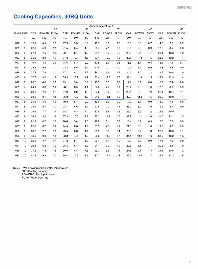
Dimensions / Clearances
30RB/RQ017~021
Model A B C D E F G H I30RB/RQ017 1100 1580 500 659 222 530 112 700 4830RB/RQ021 1100 1580 500 659 222 530 112 700 48
30RB/RQ026~033
Model A B C D E F G H I J30RB/RQ026 1800 215 105 138 38 755 397 245 500 99030RB/RQ033 1800 215 105 138 38 755 397 245 500 990
A
E D
BF C
GH
I
Power Supply Hole
A
BC
D
E
F
H I
J
GPower Supply Hole
30RB/RQ017~021
30RB/RQ026~033
Model A B C D E30RB/RQ017 200 300 400 500 100030RB/RQ021 200 300 400 500 1000
Model A B C D30RB/RQ026 400 500 200 180030RB/RQ033 400 500 200 1800
A
BB
C
A C
D
E B
D
A C
B

10
30RB/RQ
Electrical Connection30RB017~021
30RB026~033
1 CONTROL BOARD 2 ODU POWER TERMINAL BLOCK 3 HMI TERMINAL BLOCK 4 HUMAN MACHINE INTERFACE (HMI) 5 MAIN POWER SWITCH 6 TIME-DELAY FUSE OR BREAKER 7 ODU CONTROLTERMINAL BLOCK 8 REMOTE CONTROLLER TERMINAL 9 REMOTE CONTROLLER10 OUTPUT FOR USER PUMP CONTROL (OPTION)11 USER FLOW SWITCH CONNECTION (OPTION)12 FAN COIL INTERLOCK CONTROLLER
1 CONTROL BOARD 2 ODU POWER TERMINAL BLOCK 3 HMI TERMINAL BLOCK 4 HUMAN MACHINE INTERFACE (HMI) 5 MAIN POWER SWITCH 6 TIME-DELAY FUSE OR BREAKER 7 ODU CONTROLTERMINAL BLOCK 8 REMOTE CONTROLLER TERMINAL 9 REMOTE CONTROLLER10 OUTPUT FOR USER PUMP CONTROL (OPTION)11 USER FLOW SWITCH CONNECTION (OPTION)12 FAN COIL INTERLOCK CONTROLLER
LEGEND:PE EARTHL1 LIVE POWER SUPPLYL2 LIVE POWER SUPPLYL3 LIVE POWER SUPPLYN NEUTRAL POWER SUPPLY
LEGEND:PE EARTHL1 LIVE POWER SUPPLYL2 LIVE POWER SUPPLYL3 LIVE POWER SUPPLYN NEUTRAL POWER SUPPLY
400V
-3-5
0Hz
400V
-3-5
0Hz

11
30RB/RQ
Electrical Connection
30RQ026~033
30RQ017~021
1 CONTROL BOARD 2 ODU POWER TERMINAL BLOCK 3 HMI TERMINAL BLOCK 4 HUMAN MACHINE INTERFACE (HMI) 5 MAIN POWER SWITCH 6 TIME-DELAY FUSE OR BREAKER 7 ODU CONTROLTERMINAL BLOCK 8 REMOTE CONTROLLER TERMINAL 9 REMOTE CONTROLLER10 OUTPUT FOR USER PUMP CONTROL (OPTION)11 USER FLOW SWITCH CONNECTION (OPTION)12 FAN COIL INTERLOCK CONTROLLER
1 CONTROL BOARD 2 ODU POWER TERMINAL BLOCK 3 HMI TERMINAL BLOCK 4 HUMAN MACHINE INTERFACE (HMI) 5 MAIN POWER SWITCH 6 TIME-DELAY FUSE OR BREAKER 7 ODU CONTROLTERMINAL BLOCK 8 REMOTE CONTROLLER TERMINAL 9 REMOTE CONTROLLER10 OUTPUT FOR USER PUMP CONTROL(OPTION)11 USER FLOW SWITCH CONNECTION (OPTION)12 FAN COIL INTERLOCK CONTROLLER
LEGEND:PE EARTHL1 LIVE POWER SUPPLYL2 LIVE POWER SUPPLYL3 LIVE POWER SUPPLYN NEUTRAL POWER SUPPLY
LEGEND:PE EARTHL1 LIVE POWER SUPPLYL2 LIVE POWER SUPPLYL3 LIVE POWER SUPPLYN NEUTRAL POWER SUPPLY
400V
-3-5
0Hz
400V
-3-5
0Hz

12
30RB/RQ
Electrical ConnectionWiring of fan coils interlock Controller
Controller installation & keyboard introduction
Unit supply area
Installation instruction:1. Please shut off the power before wiring2. The specs of wire purchased by customer is 0.5mm2 BVR and the length is due to actual situation.Advised length is within 100m3. It is recommended that you shoud ensure at least one solenoid valve of fan coil is ON when the chiller is reset after alarm.4. Please shut off the power before maintenance. Until to 10 seconds later, you can contact the controller after the capacitor fully discharge.
Pro-Dialog Plus Controller (Human Machine Interface) Demonstration
Remote controller Demonstration
Neutral line
N
J1
#1
J2
#2
J3
#3
J4
#4
J5
#5
J6
#6
J7
#7
J8
#8
L X1 X2
TB3
TB1 TB2
79
1315
11
5
11 123
162
120
Contrast button
Running indicator
Downward navigation key
Upward navigation key
Confirm
Alarm
On/ OffMode selection
Back
Power
Min. Max.
400-3-50 360 440
Neutral line Live line Live line
N
J1
#1
J2
#2
J3
#3
J4
#4
J5
#5
J6
#6
J7
#7
J8
#8
L X1 X2
TB3
TB1 TB2
N
J1
#9
J2
#10
J3
#11
J4
#12
J5
#13
J6
#14
J7
#15
J8
#16
L X1 X2
TB3
TB1 TB2
I EI
E
124
80
Energy saving mode
Alarm Heating mode indicatorCooling mode indicatorEnergy saving mode indicator
Power on indicatorOn/Off
Cooling/Heating
24
② Cable③ To 30RB/RQ chiller④ Hard PVC pipe, Min. 30mm ID⑤ Wall (around 30mm thickness)⑥ Remote controller⑦ Wiring channels
②
③
⑥ ⑦
④⑤
③
⑥
④⑤
⑦
36
CARRIER Part No.00PSY120086600CARRIER Part No.00PSY120086600 CARRIER Part No.00PSY120086600
Wiring diagram between fan coils and chillerLess than 8 fan coil units More than 8 fan coil units
Connect to input live line of solenoid valve of fan coil
Connect to input live line of solenoid valve of fan coil
Connect to input live line of solenoid valve of fan coil
Terminal Blck B6 of unit
Terminal Block#6 of remote controller
Live line
Neutral line
Terminal Blck B6 of unitTerminal Block #6of remote controller
②
②
13
30RB/RQ
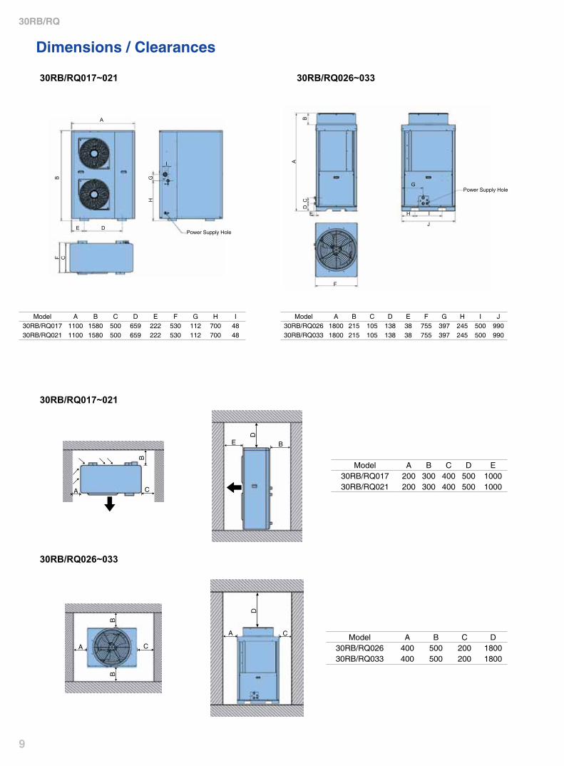
30RB/RQ Model 017 021 026 033
Water loop volume IMin. 66 81 98 125
30RQ Max. 93 114 147 18830RB Max. 125 155 195 240
It'softennecessarytoaddabufferwatertanktothecircuitinordertoachievetherequiredvolume.Thetankmustitselfbeinternallybaffledinordertoensurepropermixingoftheliquid(waterorbrine).Refertotheexamplesbelow.
Water System Specifications
Pump Head - Flow rate Curve
Available external static pressure of standard units Water temperature: 20℃
Internal water pressure drop for units without hydronic kits
300280260240220200180160140120100
1201101009080706050403020
0.5 0.7 0.9 1.1 1.3 1.5 1.7 1.9 2.1 2.3 2.5
0.5 1 1.5 2 2.5
Ava
ilabl
e w
ater
pre
ssur
e kP
aP
ress
ure
drop
kP
a
Flow ratel/s
Flow ratel/s
Corrective Factors for EG solution
10%
-4℃
0.996
0.990
1.000
1.003
20%
-9℃
0.991
0.978
0.979
1.010
30%
-15℃
0.983
0.964
0.979
1.020
40%
-23℃
0.974
1.008
1.025
1.033
①②
③④
① ②③
④
① 30RB/RQ017② 30RB/RQ021③ 30RB/RQ026④ 30RB/RQ033
① 30RB/RQ017② 30RB/RQ021③ 30RB/RQ026④ 30RB/RQ033
EG
Ice point
Capacity
Input power
Water velocity
Water Pressure drop
EG: Ethylene glycol
Bad BadGood Good

14
30RB/RQ
Water Connections
Water connections
Difference in height between water chiller and highest system point
30RB/RQ 017~021 30RB/RQ 026~033
4 21
2
14
3
Max
. 20
m
Typical water circuit diagram
1 Unit water inlet Ø 1 1/4”F Gas2 Unit water outlet Ø 1 1/4”F Gas3 Drain valve4 Manual air vent valveNote: Drain valve is not included in the units without hydronic kits
Hydronic kits in standard units Parts installed by users1 Manual air vent valve 11 Flexible connector2 Safety valve (not included in the units without hydronic kits) 12 Pressure gauge3 Expansion tank (not included in the units without hydronic kits) 13Waterfilter4 Water Pump (not included in the units without hydronic kits) 14 Manual shut-off valve5 Auto air vent valve (not included in the units without hydronic kits) 15Waterfillingvalve(Itisrecommendedtouseauto-fillingvalvewith
pressure relief function)6 Water temperature sensor7 BPHE heater 16 Air vent valve **8 BPHE9 Flow switch (not included in the units without hydronic kits)*10 Drain valve (not included in the units without hydronic kits)*
Note: *Forstandardunits30RB/RQ017~021,flowswitchanddrainvalveareinstalledonthewaterinletpipe.Pleasenotethatthedrainvalveofthese models can not evacuate water in BPHE. So users need to install a drain valve on water outlet pipe if the water in BPHE need be evacuated in winter.** Air vent valve must be installed in the highest position of the circuit. For units without hydronic kits, users need to install all related parts referring to the above diagram.
12
11
10
21
3
4 5
6
68
714
15
1416
13 12
11
9

15
30RB/RQ
System Applications
Aquasnap(Standard integrated with hydronic module and fan coil Interlock control)
001 002 003 004 005 006 008 010 012 014 Recommended applications
42CN
Cooling capacity (kW) 1.3 2.2 3.2 4.0 4.8 5.8 7.8 9.1 10.9 13.0
Hotel, Apartment, Villa and OfficeHeating
capacity (kW) 2.1 3.4 5.0 6.2 7.5 9.0 12.2 14.2 17.0 20.2
42GWC
Cooling capacity (kW) - - 2.4 4.0 4.7 5.9 8.3 11.0 - -
Office, meeting room and other kinds of business occasionsHeating
capacity (kW) - - 4.5 6.5 7.7 9.9 12.5 16.9 - -
Carrier is dedicated to improve your quality of life by creating comfortable, healthy environments in which to live. To ahieve this, we design and develop the appropriate air conditioning system in connection with various conditions, covering chiller, airside equipments and control system and so on a series of priducts. We can combine the most complete variety of products into appropriate air-condition systems to meet different demand of customers.
Aimming at villa, appartment, club, suppermarket and business hall, Carrier developed small central air conditioning system for client to provide cooling and heating, which integrated Aquasnap series air-cooled liquid chiller/heat pump, low noise fan coil and control.
Whatever extremely hot or severely cold, you can enjoy a comfortable life!
Recommended fan coil units
42GWC casette fan coil
Note: 1. Cooling capacity is messured at below conditions: Entering water temperature7℃ , Delta T5℃ ; Inlet air temperature 27℃ (DB)/19.5℃ (WB) 2. Heating capacity is messured at below conditions: Entering water temperature60℃ ; Inlet air tempture 21℃ 3. Please contact local carrier sales entity if you need more information on airside products.
42CN fan coil with low noise

E-SNGA-1103-02-CHK
we, as a world manufacturer, balance our curtomer' needs for comfort with the environment'sneeds for responsible consumption.
Welcome to Carrier Websitew w w . c a r r i e r . c o m . c n
All Rights Reserved Carrier