Embed Size (px)
Citation preview
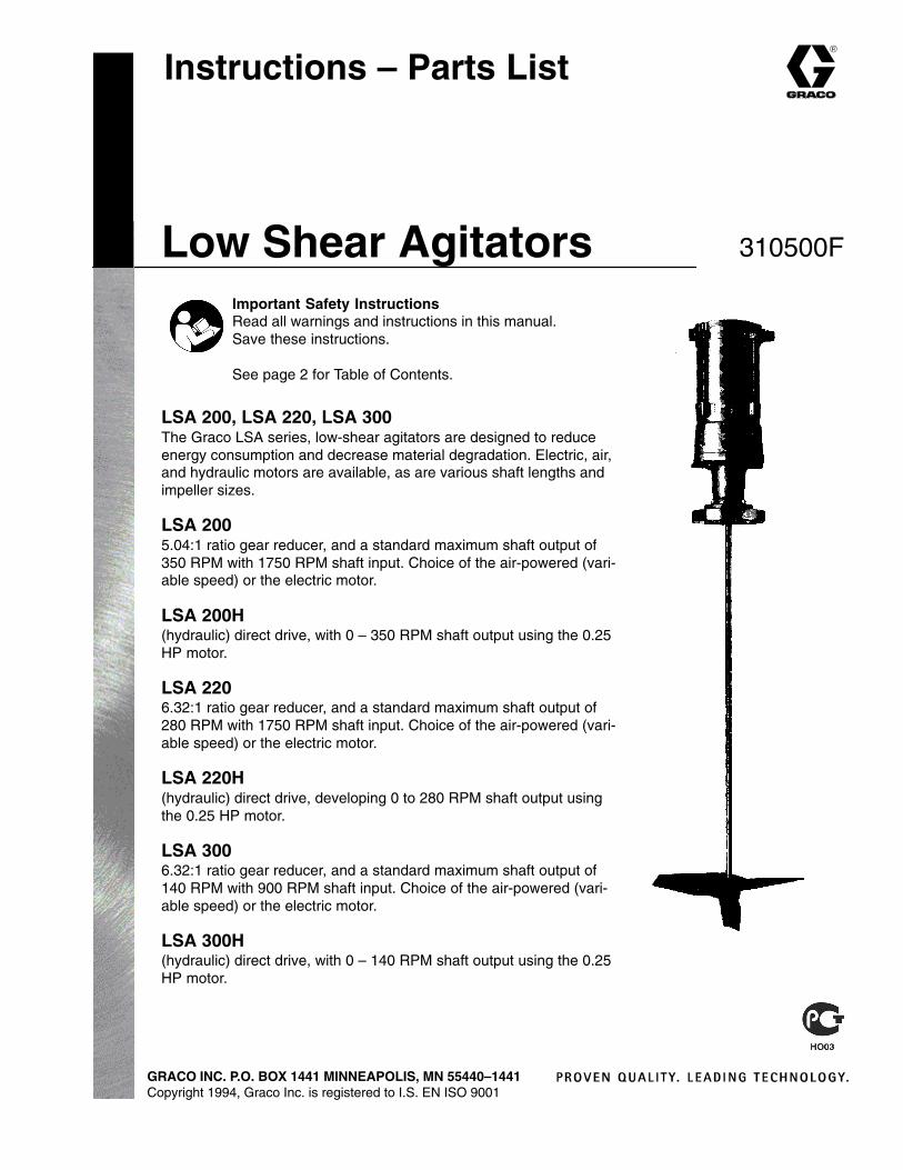
Instructions – Parts List
GRACO INC. P.O. BOX 1441 MINNEAPOLIS, MN 55440–1441Copyright 1994, Graco Inc. is registered to I.S. EN ISO 9001
Low Shear Agitators
LSA 200, LSA 220, LSA 300The Graco LSA series, low-shear agitators are designed to reduceenergy consumption and decrease material degradation. Electric, air,and hydraulic motors are available, as are various shaft lengths andimpeller sizes.
LSA 2005.04:1 ratio gear reducer, and a standard maximum shaft output of350 RPM with 1750 RPM shaft input. Choice of the air-powered (vari-able speed) or the electric motor.
LSA 200H(hydraulic) direct drive, with 0 – 350 RPM shaft output using the 0.25HP motor.
LSA 2206.32:1 ratio gear reducer, and a standard maximum shaft output of280 RPM with 1750 RPM shaft input. Choice of the air-powered (vari-able speed) or the electric motor.
LSA 220H(hydraulic) direct drive, developing 0 to 280 RPM shaft output usingthe 0.25 HP motor.
LSA 3006.32:1 ratio gear reducer, and a standard maximum shaft output of140 RPM with 900 RPM shaft input. Choice of the air-powered (vari-able speed) or the electric motor.
LSA 300H(hydraulic) direct drive, with 0 – 140 RPM shaft output using the 0.25HP motor.
310500F
Important Safety InstructionsRead all warnings and instructions in this manual.Save these instructions.
See page 2 for Table of Contents.
� ������
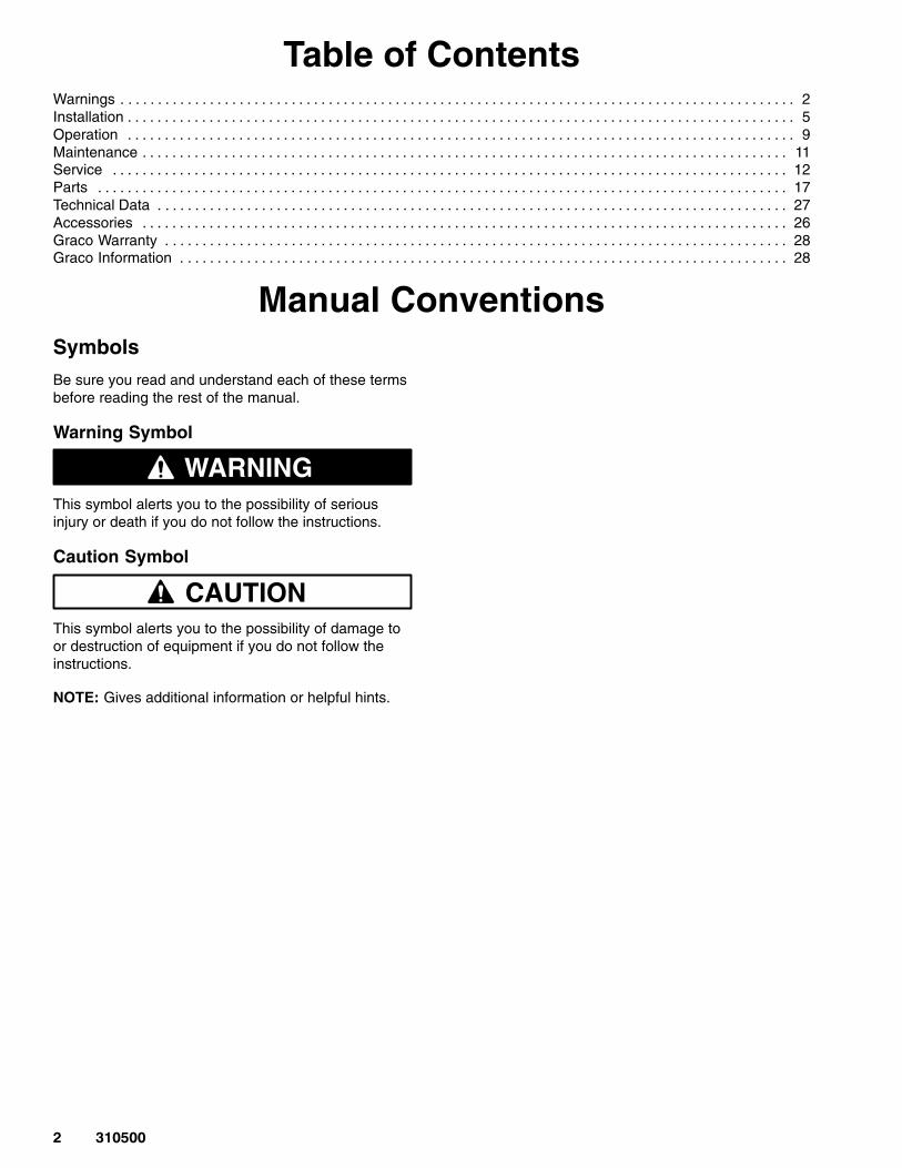
Table of ContentsWarnings 2. . . . . . . . . . . . . . . . . . . . . . . . . . . . . . . . . . . . . . . . . . . . . . . . . . . . . . . . . . . . . . . . . . . . . . . . . . . . . . . . . . . . . . . . . . . Installation 5. . . . . . . . . . . . . . . . . . . . . . . . . . . . . . . . . . . . . . . . . . . . . . . . . . . . . . . . . . . . . . . . . . . . . . . . . . . . . . . . . . . . . . . . . . Operation 9. . . . . . . . . . . . . . . . . . . . . . . . . . . . . . . . . . . . . . . . . . . . . . . . . . . . . . . . . . . . . . . . . . . . . . . . . . . . . . . . . . . . . . . . . . Maintenance 11. . . . . . . . . . . . . . . . . . . . . . . . . . . . . . . . . . . . . . . . . . . . . . . . . . . . . . . . . . . . . . . . . . . . . . . . . . . . . . . . . . . . . . . Service 12. . . . . . . . . . . . . . . . . . . . . . . . . . . . . . . . . . . . . . . . . . . . . . . . . . . . . . . . . . . . . . . . . . . . . . . . . . . . . . . . . . . . . . . . . . . Parts 17. . . . . . . . . . . . . . . . . . . . . . . . . . . . . . . . . . . . . . . . . . . . . . . . . . . . . . . . . . . . . . . . . . . . . . . . . . . . . . . . . . . . . . . . . . . . . Technical Data 27. . . . . . . . . . . . . . . . . . . . . . . . . . . . . . . . . . . . . . . . . . . . . . . . . . . . . . . . . . . . . . . . . . . . . . . . . . . . . . . . . . . . . Accessories 26. . . . . . . . . . . . . . . . . . . . . . . . . . . . . . . . . . . . . . . . . . . . . . . . . . . . . . . . . . . . . . . . . . . . . . . . . . . . . . . . . . . . . . . Graco Warranty 28. . . . . . . . . . . . . . . . . . . . . . . . . . . . . . . . . . . . . . . . . . . . . . . . . . . . . . . . . . . . . . . . . . . . . . . . . . . . . . . . . . . . Graco Information 28. . . . . . . . . . . . . . . . . . . . . . . . . . . . . . . . . . . . . . . . . . . . . . . . . . . . . . . . . . . . . . . . . . . . . . . . . . . . . . . . . .
Manual ConventionsSymbols
Be sure you read and understand each of these termsbefore reading the rest of the manual.
Warning Symbol
WARNINGThis symbol alerts you to the possibility of seriousinjury or death if you do not follow the instructions.
Caution Symbol
CAUTIONThis symbol alerts you to the possibility of damage toor destruction of equipment if you do not follow theinstructions.
NOTE: Gives additional information or helpful hints.
�������
FIRE, EXPLOSION, AND ELECTROSTATIC SHOCK HAZARDImproper grounding, poor air ventilation, open flames or sparks can cause a hazardous conditionand result in fire or explosion and serious injury.
� Ground the equipment and the object being sprayed.
� If there is any static sparking while using the equipment, stop dispensing immediately. Identifyand correct the problem.
� Provide fresh air ventilation to avoid the buildup of flammable fumes from solvent or material.
� Do not smoke in the dispense area.
� Extinguish all open flames or pilot lights in the dispense area.
� Do not turn on or off any light switch in the dispense area.
� Keep the dispense area free of debris, including solvent, rags and gasoline.
� Keep a fire extinguisher in the work area.
MOVING PARTS HAZARDMoving parts, such as an impeller blade, can pinch or amputate fingers.
� Keep clear of any moving parts when starting or operating the equipment.
� Disconnect the power supply before checking or servicing the equipment to prevent starting itaccidentally.
� For hydraulic driven units, follow the Pressure Relief Procedure before checking or servicingthe agitator to prevent it from starting accidentally.
HOT SURFACE HAZARD� The surfaces of equipment which dispense hot materials can become heated enough to cause
burns if touched. When working with such equipment, wear appropriate protective gloves andclothing. Allow hot surfaces time to cool, if possible, before servicing.
TOXIC FLUID HAZARDThe improper handling of hazardous fluids or inhaling toxic fumes can cause extremely serious in-jury, even death, due to splashing in the eyes, ingestion, or bodily contamination.
� Know the specific hazards of the fluid you are using.
� Store hazardous fluid in an approved container. Dispose of hazardous fluid according to all local,state and national guidelines.
� Wear appropriate clothing, gloves, eyewear and respirator.
� Pipe and dispose of the exhaust air safely. See your separate pump manual for further informa-tion.
WARNINGWARNING
� ������
EQUIPMENT MISUSE HAZARD
Equipment misuse can cause the equipment to rupture, malfunction or start unexpectedly and resultin serious injury.
� This equipment is for professional use only.
� Read all instruction manuals, tags, and labels before operating the equipment.
� Use the equipment only for its intended purpose. If you are uncertain about the usage, call GracoTechnical Assistance at (313) 416–3400.
� Do not alter or modify this equipment. Use only genuine Graco parts and accessories.
� Check the equipment daily. Repair or replace any worn or damaged parts immediately.
� Do not exceed the power supply requirement of the electrical equipment.
� For air-powered and hydraulic-powered agitators, the Maximum Input Pressure depends on themodel type – refer to the Technical Data section on page 23. Never exceed these pressures.
� Be sure that all accessories on the system’s air and/or hydraulic power lines are rated to with-stand the system pressure. Never exceed the maximum working pressure of the lowest-ratedcomponent in your system.
� Do not move or lift any pressurized equipment.
� Use fluids or solvents that are compatible with equipment wetted parts. See the Technical Datasection of all equipment manuals. Read the fluid and solvent manufacturer’s warnings.
� The fluid hoses must have spring guards on both ends to protect them from rupture caused bykinks or bends at or close to the couplings.
� Comply with all applicable local, state and national fire, electrical and other safety regulations.
ELECTRIC SHOCK HAZARD
Beware of HIGH VOLTAGE in systems with electrical equipment. CONTACT WITH HIGH VOLTAGEELECTRICITY CAN BE FATAL!
� Be sure all electrical installations and service is performed by a qualified electrician only.
� Be sure electrical installations comply with applicable codes.
� Be sure power is disconnected when servicing and repairing equipment.
WARNINGWARNING
�������
InstallationFor best results, do not remove any protective wrap-pings from any of the agitator parts until just prior toassembly and installation. Also, store the agitator partsindoors, in clean, dry air, with an ambient temperaturebetween 59� – 104� F (15� – 40� C).
Impeller Installation
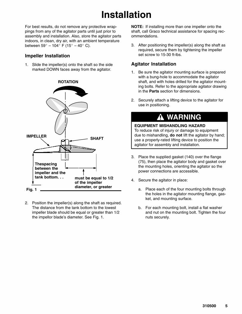
1. Slide the impeller(s) onto the shaft so the sidemarked DOWN faces away from the agitator.
Fig. 1
SHAFTIMPELLER
Thespacingbetween theimpeller and the tank bottom. . . must be equal to 1/2
of the impeller diameter, or greater
ROTATION
2. Position the impeller(s) along the shaft as required.The distance from the tank bottom to the lowestimpeller blade should be equal or greater than 1/2the impellor blade’s diameter. See Fig. 1.
NOTE: If installing more than one impeller onto theshaft, call Graco technical assistance for spacing rec-ommendations.
3. After positioning the impeller(s) along the shaft asrequired, secure them by tightening the impellerset screw to 15-30 ft-lbs.
Agitator Installation
1. Be sure the agitator mounting surface is preparedwith a bung-hole to accommodate the agitatorshaft, and with holes drilled for the agitator mount-ing bolts. Refer to the appropriate agitator drawingin the Parts section for dimensions.
2. Securely attach a lifting device to the agitator foruse in positioning.
EQUIPMENT MISHANDLING HAZARDTo reduce risk of injury or damage to equipmentdue to mishandling, do not lift the agitator by hand;use a properly-rated lifting device to position theagitator for assembly and installation.
WARNING
3. Place the supplied gasket (140) over the flange(75), then place the agitator body and gasket overthe mounting holes, orienting the agitator so thepower connections are accessible.
4. Secure the agitator in place:
a. Place each of the four mounting bolts throughthe holes in the agitator mounting flange, gas-ket, and mounting surface.
b. For each mounting bolt, install a flat washerand nut on the mounting bolt. Tighten the fournuts securely.
� ������
InstallationShaft Installation
1. Check the access hole in the drive unit housing tosee if the drive quill set screw (58) is accessible(see Fig. 2).
Fig. 2
2. If the drive quill set screw is not accessible, jog themotor to align the drive quill (35):
MOVING PARTS HAZARDMoving equipment parts can cause inju-ry, including amputating of hands or fin-gers. To reduce risk of injury or equip-
ment damage, do not jog the motor with the shaftand impeller in the drive quill.
WARNING
a. Refer to the Power Connection section foryour motor type to connect power to motor.
b. Supply power in short intervals, rotating thedrive quill until the drive quill set screw is ac-cessible by a hex wrench.
c. Disconnect the power from the motor.
3. With power disconnected, insert the top end of theshaft into the drive quill so that the shaft contactsthe top of the quill.
4. With the shaft fully inserted into the drive quill, usea hex key wrench to secure the set screw.
Connecting Power
T1T2T3
MOTOR WIRING
3 PHASE SINGLE VOLTAGEWITH THERMAL PROTECTOR
3 PHASE DUAL VOLTAGEWITH THERMAL PROTECTOR
LOWVOLTAGE
HIGHVOLTAGE
T1T2T3
L1L2L3 T1
T2T3
14
256
3
THERMALPROTECTOR
T1
T2T3
14
2563
THERMALPROTECTOR
T4
T7
T8T5
T9T6
L1
L2
L3
T1
T7T2
T8T3
T9
T4
T5
T6
L1L2L3
T4
T7T5
T8T6
T9
NOTE: TO REVERSE ROTATION, INTERCHANGE ANY TWO LINE LEADS (L1, L2, or L3)
Fig. 3
P1P2
THERMOSTATLEADS} P1
P2THERMOSTATLEADS}
CONNECT LEADS P1 AND P2 IN SERIES WITH THE HOLDINGCOIL OF THE MOTOR CONTROLLER WHICH USES A MANUAL MOMENTARY START SWITCH.
�������
InstallationConnecting Power (cont.’d)
Electric Agitators
Refer to the motor wiring diagram (Fig. 3).
The required power supply varies depending on yourmodel number. For the power supply requirements,see the Technical Data in this manual.
WARNINGELECTROCUTION HAZARDMake sure that your installation complieswith National, State, and Local codes forthe installation of electrical equipment.
Have only a qualified electrician make the connec-tions.
1. Verify the electrical supply and control equipmentis properly rated for the motor being used.
2. Check the stator winding insulation resistance. Ifthe resistance is less than 1 megohm, call GracoCustomer Service for assistance.
3. With the power disconnected, connect all the elec-trical leads as indicated in the wiring diagram.
ELECTROCUTION HAZARDContact with electricity can be fatal! Toreduce risk of serious injury or death,make sure the power supply lines to the
agitator are disconnected from the power supplywhen servicing and repairing the equipment.
WARNING
NOTE: The blade rotation should be clockwise, look-ing down from the motor to the blade. To change thedirection of rotation, disconnect power from the agita-tor power supply lines, and change the leads as indi-cated in Fig. 3.
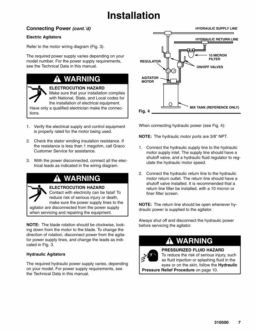
Hydraulic Agitators
The required hydraulic power supply varies, dependingon your model. For power supply requirements, seethe Technical Data in this manual.
AGITATORMOTOR
Fig. 4
HYDRAULIC SUPPLY LINE
HYDRAULIC RETURN LINE
10 MICRON FILTER
ON/OFF VALVES
MIX TANK (REFERENCE ONLY)
REGULATOR
When connecting hydraulic power (see Fig. 4):
NOTE: The hydraulic motor ports are 3/8” NPT.
1. Connect the hydraulic supply line to the hydraulicmotor supply inlet. The supply line should have ashutoff valve, and a hydraulic fluid regulator to reg-ulate the hydraulic motor speed.
2. Connect the hydraulic return line to the hydraulicmotor return outlet. The return line should have ashutoff valve installed. It is recommended that areturn line filter be installed, with a 10 micron orfiner filter screen.
NOTE: The return line should be open whenever hy-draulic power is supplied to the agitator.
Always shut off and disconnect the hydraulic powerbefore servicing the agitator.
PRESSURIZED FLUID HAZARDTo reduce the risk of serious injury, suchas fluid injection or splashing fluid in theeyes or on the skin, follow the Hydraulic
Pressure Relief Procedure on page 10.
WARNING
������
InstallationConnecting Power (cont.’d)
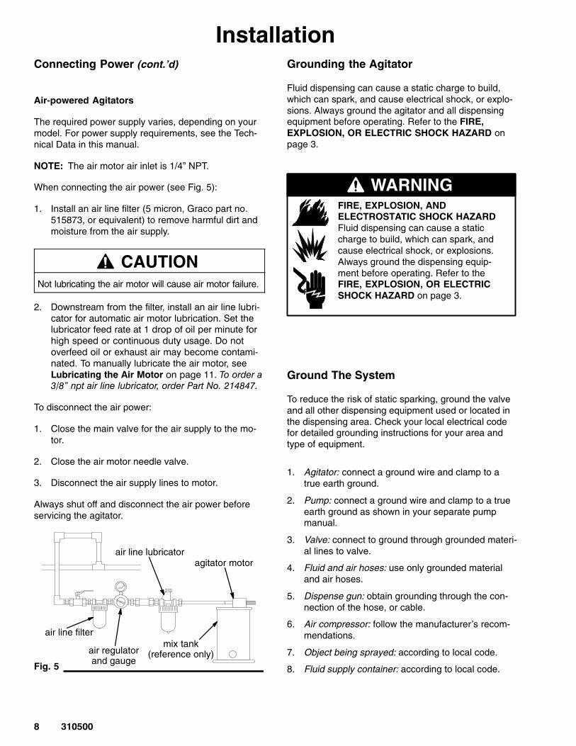
Air-powered Agitators
The required power supply varies, depending on yourmodel. For power supply requirements, see the Tech-nical Data in this manual.
NOTE: The air motor air inlet is 1/4” NPT.
When connecting the air power (see Fig. 5):
1. Install an air line filter (5 micron, Graco part no.515873, or equivalent) to remove harmful dirt andmoisture from the air supply.
CAUTIONNot lubricating the air motor will cause air motor failure.
2. �������������� ���������������������������������
����������������������������������������� �������������������������������������������������
�� ��������������������������������������
������������������ ���������������������
������������������������� ��������������
�� �������������� ����� �������������������������� ��������������������������������������������
To disconnect the air power:
1. Close the main valve for the air supply to the mo-tor.
2. Close the air motor needle valve.
3. Disconnect the air supply lines to motor.
Always shut off and disconnect the air power beforeservicing the agitator.
air line lubricatoragitator motor
air line filter
air regulatorand gauge
mix tank(reference only)
Fig. 5
Grounding the Agitator
Fluid dispensing can cause a static charge to build,which can spark, and cause electrical shock, or explo-sions. Always ground the agitator and all dispensingequipment before operating. Refer to the FIRE,EXPLOSION, OR ELECTRIC SHOCK HAZARD onpage 3.
WARNINGFIRE, EXPLOSION, AND ELECTROSTATIC SHOCK HAZARDFluid dispensing can cause a staticcharge to build, which can spark, andcause electrical shock, or explosions.Always ground the dispensing equip-ment before operating. Refer to theFIRE, EXPLOSION, OR ELECTRICSHOCK HAZARD on page 3.
Ground The System
To reduce the risk of static sparking, ground the valveand all other dispensing equipment used or located inthe dispensing area. Check your local electrical codefor detailed grounding instructions for your area andtype of equipment.
1. Agitator: connect a ground wire and clamp to atrue earth ground.
2. Pump: connect a ground wire and clamp to a trueearth ground as shown in your separate pumpmanual.
3. Valve: connect to ground through grounded materi-al lines to valve.
4. Fluid and air hoses: use only grounded materialand air hoses.
5. Dispense gun: obtain grounding through the con-nection of the hose, or cable.
6. Air compressor: follow the manufacturer’s recom-mendations.
7. Object being sprayed: according to local code.
8. Fluid supply container: according to local code.
�������
OperationGeneral Operation
MOVING PARTS HAZARDMoving parts, such as an impeller blade,can pinch or amputate fingers. To reducerisk of injury or damage to equipment,
before supplying power to equipment:
1. Be sure the agitator shaft rotates freely byhand; the movement of the shaft and impellermust not be hindered by the container, pump,or any other objects.
2. Be sure the cap screws and set screws aretightened as required.
3. Be sure all the protective guards and coversare in place.
WARNING
To connect the power to the agitator, see the PowerConnection section. Disconnect the power supply be-fore checking or servicing the agitator.
Activate the agitator to mix fluid thoroughly before sup-plying fluid to the dispensing equipment. Continuemixing fluid while the dispensing equipment is beingsupplied.
NOTE: Always use moderate agitation speeds; exces-sive agitator speed may cause vibration, foaming offluid and increased wear on parts.
HOT SURFACE HAZARDDuring operation, the motor can get hotenough to cause burns if touched. Whenworking with such equipment, wear ap-
propriate protective gloves and clothing. Allow themotor to cool for at least one hour power beforetouching either the motor or the shaft near themotor, which can also get hot.
WARNING
Operation – Electric Motor
The agitator speed is fixed for electric motor models;the specific speed depends on the model type. See theTechnical Data for your model type for electrical re-quirements.
1. To start the agitator, turn on the electric power tothe motor.
2. To stop the agitator, turn off the electrical power tothe motor. Disconnect the electrical power beforechecking or servicing the agitator.
NOTE: The motor has thermal protection circuitrywhich shuts down the motor if overheating occurs. Ifthis happens, disconnect power and recheck your wir-ing connections and electrical supply.
MOVING PARTS HAZARDThe thermal protection circuit resets au-tomatically when the motor cools down.To reduce the risk of injury or damage to
equipment, always disconnect the power supplybefore checking or servicing the agitator motor.
WARNING
Operation – Air Motor
The agitator speed for air motor models is variableover a certain range, depending on the model type.See the Technical Data for your model type.
1. To start the agitator, turn on the air supply andslowly open the air needle valve.
2. To stop the agitator slowly close the air needlevalve.
Turn off the air supply and disconnect the air hosefrom the air motor before servicing the agitator.
�� ������
OperationOperation – Hydraulic Motor
The agitator speed for hydraulic motor models is vari-able over a certain range, depending on the modeltype. See the Technical Data for your model type.
To start the agitator:
1. Open the shutoff valve at the hydraulic return line.
2. Open the shutoff valve on the hydraulic supply lineto the agitator.
3. Adjust the regulator to increase or decrease theagitator speed.
4. To stop the agitator, close the hydraulic shutoffvalve in the hydraulic supply line.
Disconnect the power supply before checking or serv-icing the agitator.
PRESSURIZED FLUID HAZARDTo reduce the risk of serious injury, suchas fluid injection or splashing fluid in theeyes or on the skin, follow the Hydraulic
Pressure Relief Procedure.
WARNING
Hydraulic Pressure Relief Procedure
For hydraulic agitators, to reduce the risk of seriousbodily injury, including splashing in the eyes or on theskin, and injury from moving parts, always follow thisprocedure whenever you shut off the agitator, and be-fore inspecting, removing, cleaning or repairing theagitator.
1. Shut off the main hydraulic power supply.
2. Close the regulator to the motor.
3. Shut off the hydraulic return valve.
4. Disconnect the hydraulic lines to the agitator.
��������
Maintenance
MOVING PARTS HAZARDMoving parts, such as an impeller blade,can pinch or amputate fingers. To reducerisk of injury or damage to equipment,
always disconnect power from the agitator beforeperforming maintenance or service.
WARNING
HOT SURFACE HAZARDDuring operation, the motor can get hotenough to cause burns if touched. Whenworking with such equipment, wear ap-
propriate protective gloves and clothing. Allow themotor to cool for at least one hour with power re-moved before touching either the motor or the shaftnear the motor, which can also get hot.
WARNING
Check Screw and Bolt TightnessWithin the first two weeks of operation, check all capscrews and set screws to make sure the screws aretightened. Retighten as required.
Routine Periodic MaintenanceCheck and retighten all cap screws every six monthsor during down times if they occur more frequently.
Gear Housing Grease CheckNOTE: This procedure does not pertain to hydraulicmodels, nor to the LSA 100 model, which do not havegear housings.
The gear housing is factory filled with grease; thisgrease normally does not need to be changed, unlessambient air conditions are harsh, or unless some otherservice is being performed.
Harsh air conditions, including high humidity, dusty orchemical laden air, or widely varying air temperatures,can increase the deterioration of the grease.
If harsh conditions are present, check the grease atleast every six months for deterioration. If necessary,replace the grease. See the Gear Reducer Lubrica-tion heading in the Service section.
CAUTIONUse only Mobil Mobilith SHC 007 lubricant to lubri-cate the gear housing. The use of any other maycause part deterioration or inadequate perfor-mance.
Power Supply System Check
Check your power supply system equipment regularlyand repair or replace worn or damaged parts immedi-ately. Have the supply system maintenance performedby a qualified technician only.
Air Motor Flush
If the air motor performs sluggishly, try flushing with asuitable solvent (recommended solvents include GastFlushing Solvent AH255, Loctite Safety Solvent, Inhibi-sol Safety Solvent, or Dow Chemical Chlorothane).
TOXIC FLUIDS HAZARDImproper handling of hazardous fluids orinhaling toxic fumes can cause ex-tremely serious injury, even death, due
to splashing in the eyes, ingestion, or bodily conta-mination. See Toxic Fluids Hazard on page 3.
WARNING
To flush the air motor:
1. Shut off air supply to the motor, and disconnect airline from motor.
2. Pour several teaspoons of solvent directly into mo-tor through the air inlet.
3. Rotate the motor by hand, if possible, in bothdirections, for a few minutes.
4. Reconnect the air line. Open air valve, and slowlyopen needle valve until no solvent is exhausted.
If the air motor performance is still sluggish, repeat theprocedure. Further sluggish performance may indicatemotor repair or replacement.
Lubricating the Air Motor
CAUTIONNot lubricating the air motor will cause air motor failure.
If an air line lubricator is not installed, the air motormust be manually lubricated every 8 hours. Lubricatethe agitator air motor by placing 10–20 drops of SAE#10 light oil in the motor’s air inlet. Run the agitator forabout 30 seconds.
�� ������
Service
MOVING PARTS HAZARDMoving parts, such as an impeller blade,can pinch or amputate fingers. To reducerisk of injury or damage to equipment,
always disconnect power from the agitator beforeperforming maintenance or service.
WARNING
HOT SURFACE HAZARDDuring operation, the motor can get hotenough to cause burns if touched. Whenworking with such equipment, wear ap-
propriate protective gloves and clothing. Allow themotor to cool for at least one hour power beforetouching either the motor or the shaft near themotor, which can also get hot.
WARNING
TOXIC FLUIDS HAZARDImproper handling of hazardous fluids orinhaling toxic fumes can cause ex-tremely serious injury, even death, due
to splashing in the eyes, ingestion, or bodily conta-mination. See Toxic Fluids Hazard on page 3.
WARNING
Agitator and Shaft Removal
1. Make sure power is disconnected from the unit(see Power Connection).
2. Rotate the agitator shaft by hand until the drivequill set screw is accessible through the accesshole in the housing. See Fig. 2, page 6.
3. Make sure the shaft is supported, and, with a hexkey wrench, loosen the drive quill set screw twoturns to release the shaft.
4. Remove the shaft from the drive quill.
5. Remove the agitator from the tank:
a. Make sure any lifting device used is ofadequate capacity for the agitator.
b. Loosen and remove the nuts and washers se-curing the agitator to the mounting surface.
c. Lift and remove the agitator.
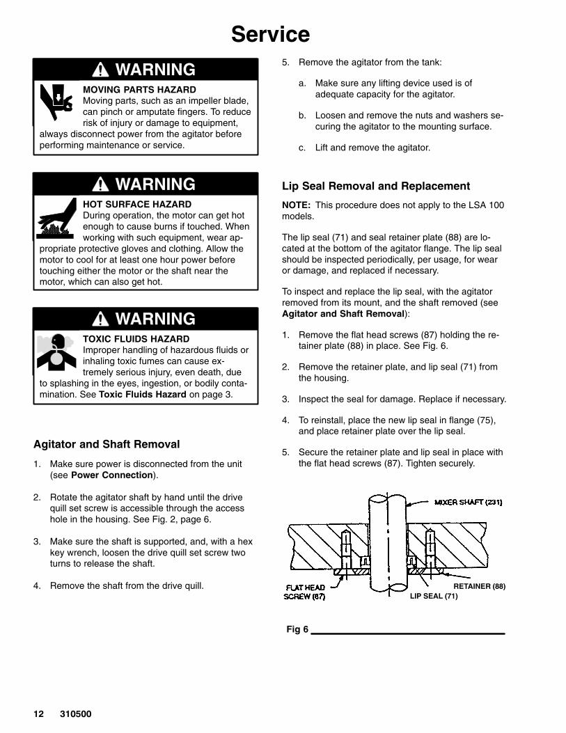
Lip Seal Removal and Replacement
NOTE: This procedure does not apply to the LSA 100models.
The lip seal (71) and seal retainer plate (88) are lo-cated at the bottom of the agitator flange. The lip sealshould be inspected periodically, per usage, for wearor damage, and replaced if necessary.
To inspect and replace the lip seal, with the agitatorremoved from its mount, and the shaft removed (seeAgitator and Shaft Removal):
1. Remove the flat head screws (87) holding the re-tainer plate (88) in place. See Fig. 6.
2. Remove the retainer plate, and lip seal (71) fromthe housing.
3. Inspect the seal for damage. Replace if necessary.
4. To reinstall, place the new lip seal in flange (75),and place retainer plate over the lip seal.
5. Secure the retainer plate and lip seal in place withthe flat head screws (87). Tighten securely.
Fig 6
RETAINER (88)LIP SEAL (71)
��������
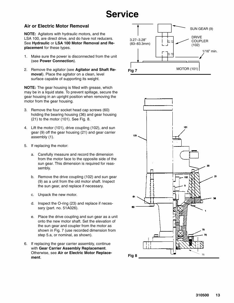
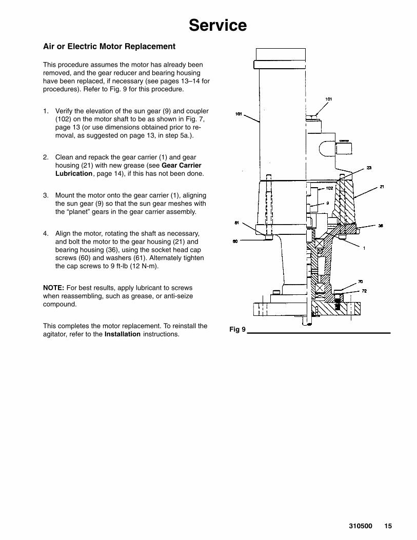
ServiceAir or Electric Motor Removal
NOTE: Agitators with hydraulic motors, and theLSA 100, are direct drive, and do have not reducers.See Hydraulic or LSA 100 Motor Removal and Re-placement for these types.
1. Make sure the power is disconnected from the unit(see Power Connection).
2. Remove the agitator (see Agitator and Shaft Re-moval). Place the agitator on a clean, levelsurface capable of supporting its weight.
NOTE: The gear housing is filled with grease, whichmay be in a liquid state. To prevent spillage, secure thegear housing in an upright position when removing themotor from the gear housing.
3. Remove the four socket head cap screws (60)holding the bearing housing (36) and gear housing(21) to the motor (101). See Fig. 8.
4. Lift the motor (101), drive coupling (102), and sungear (9) off the gear housing (21) and gear carrierassembly (1).
5. If replacing the motor:
a. Carefully measure and record the dimensionfrom the motor face to the opposite side of thesun gear. This dimension is required for reas-sembly.
b. Remove the drive coupling (102) and sun gear(9) as a unit from the old motor shaft. Inspectthe sun gear, and replace if necessary.
c. Unpack the new motor.
d. Inspect the O-ring (23) and replace if neces-sary (part. no. 51A026).
e. Place the drive coupling and sun gear as a unitonto the new motor shaft. Set the elevation ofthe sun gear and coupler from the motor asshown in Fig. 7 (use recorded dimension fromstep 5.a, or nominal, as shown).
6. If replacing the gear carrier assembly, continuewith Gear Carrier Assembly Replacement.Otherwise, see Air or Electric Motor Replace-ment.
SUN GEAR (9)
DRIVE COUPLER(102)
MOTOR (101)
3.27–3.28”(83–83.3mm)
Fig 7
1/16” min.
Fig 8 75
�� ������
ServiceGear Reducer / Bearing Assembly Replacement
This procedure assumes the motor has been removed (see Air or Electric Motor Removal, page13). Refer to Fig. 8, page 13 for this procedure.
1. Loosen and remove the socket head cap screws(70) and lock washers (72) holding the bearinghousing to the flange.
2. Remove the gear reducer and bearing housing (21and 36) from the flange (75) as an assembly.
3. Unpack the new gear reducer and bearing assem-bly (21 and 36), being very careful not to alter theorientation and alignment of the gears.
4. Install the socket head cap screws (70) and lockwashers (72) to secure the bearing housing to theflange, and tighten.
NOTE: For best results, apply lubricant to screwswhen reassembling, such as grease, or anti-seizecompound.
5. Loosen the set screw on the sun gear (9), and re-move from the new gear carrier, if desired, andreplace the old sun gear on the motor shaft. Setthe elevation of the sun gear and drive coupling(102) from the motor as shown in Fig. 7, page 13(use recorded dimension from step 5.a, or nomi-nal, as shown).
6. Pack the new gear carrier with grease (see GearCarrier Lubrication), and continue with Air orElectric Motor Replacement on page 15.
Gear Carrier Lubrication
All agitator bearings are sealed and pre-packed withlubricant. Lubrication of these bearings is not neces-sary.
Change the gear housing grease when performingservice involving motor or gear removal, or whenever agrease change is necessary due to deterioration ordiscoloration.
To change the gear housing lubricant:
1. Remove the motor from the gear housing (see Airor Electric Motor Removal). Secure the gearhousing in an upright position when removing themotor from the gear housing to avoid spillage.
2. Remove all old grease from the gear chamber andwipe clean.
3. Pack the gear chamber with fresh grease (useMobil Mobilith SHC 007 or equivalent). The hous-ing grease capacity is approximately 1 lb. (.45 kg).Fill the gear housing to a level about two inches (50mm) from the top of the housing.
CAUTIONUse only Mobil Mobilith SHC 007 lubricant to lubri-cate the gear housing. The use of any other maycause part deterioration or inadequate performance.
NOTE: When packing grease, paddle the grease,while rotating the shaft manually, and shake thehousing, for more complete coverage.
��������
ServiceAir or Electric Motor Replacement
This procedure assumes the motor has already beenremoved, and the gear reducer and bearing housinghave been replaced, if necessary (see pages 13–14 forprocedures). Refer to Fig. 9 for this procedure.
1. Verify the elevation of the sun gear (9) and coupler(102) on the motor shaft to be as shown in Fig. 7,page 13 (or use dimensions obtained prior to re-moval, as suggested on page 13, in step 5a.).
2. Clean and repack the gear carrier (1) and gearhousing (21) with new grease (see Gear CarrierLubrication, page 14), if this has not been done.
3. Mount the motor onto the gear carrier (1), aligningthe sun gear (9) so that the sun gear meshes withthe “planet” gears in the gear carrier assembly.
4. Align the motor, rotating the shaft as necessary,and bolt the motor to the gear housing (21) andbearing housing (36), using the socket head capscrews (60) and washers (61). Alternately tightenthe cap screws to 9 ft-lb (12 N-m).
NOTE: For best results, apply lubricant to screwswhen reassembling, such as grease, or anti-seizecompound.
This completes the motor replacement. To reinstall theagitator, refer to the Installation instructions.
Fig 9
�� ������
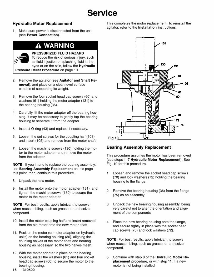
ServiceHydraulic Motor Replacement
1. Make sure power is disconnected from the unit(see Power Connection).
PRESSURIZED FLUID HAZARDTo reduce the risk of serious injury, suchas fluid injection or splashing fluid in theeyes or on the skin, follow the Hydraulic
Pressure Relief Procedure on page 10.
WARNING
2. Remove the agitator (see Agitator and Shaft Re-moval), and place on a clean level surfacecapable of supporting its weight.
3. Remove the four socket head cap screws (60) andwashers (61) holding the motor adapter (131) tothe bearing housing (36).
4. Carefully lift the motor adapter off the bearing hou-sing. It may be necessary to gently tap the bearinghousing to separate it from the adapter.
5. Inspect O-ring (43) and replace if necessary.
6. Loosen the set screws for the coupling half (103)and insert (105) and remove from the motor shaft.
7. Loosen the machine screws (130) holding the mo-tor to the motor adapter, and remove the motorfrom the adapter.
NOTE: If you intend to replace the bearing assembly,see Bearing Assembly Replacement on this pagethis point, then, continue this procedure.
8. Unpack the new motor.
9. Install the motor onto the motor adapter (131), andtighten the machine screws (130) to secure themotor to the motor adapter.
NOTE: For best results, apply lubricant to screwswhen reassembling, such as grease, or anti-seizecompound.
10. Install the motor coupling half and insert removedfrom the old motor onto the new motor shaft.
11. Position the motor (or motor adapter on hydraulicunits) on the bearing housing (36), aligning thecoupling halves of the motor shaft and bearinghousing as necessary, so the two halves mesh.
12. With the motor adapter in place on the bearinghousing, install the washers (61) and four sockethead cap screws (60) to secure the motor to thebearing housing.
This completes the motor replacement. To reinstall theagitator, refer to the Installation instructions.
Fig 10
103
105
75
Bearing Assembly Replacement
This procedure assumes the motor has been removed(see steps 1–7 Hydraulic Motor Replacement). SeeFig. 10 for this procedure.
1. Loosen and remove the socket head cap screws(70) and lock washers (72) holding the bearinghousing to the flange.
2. Remove the bearing housing (36) from the flange(75) as an assembly.
3. Unpack the new bearing housing assembly, beingvery careful not to alter the orientation and align-ment of the components.
4. Place the new bearing housing onto the flange,and secure tightly in place with the socket headcap screws (70) and lock washers (72).
NOTE: For best results, apply lubricant to screwswhen reassembling, such as grease, or anti-seizecompound.
5. Continue with step 8 of the Hydraulic Motor Re-placement procedure, or with step 11, if a newmotor is not being installed.
��������
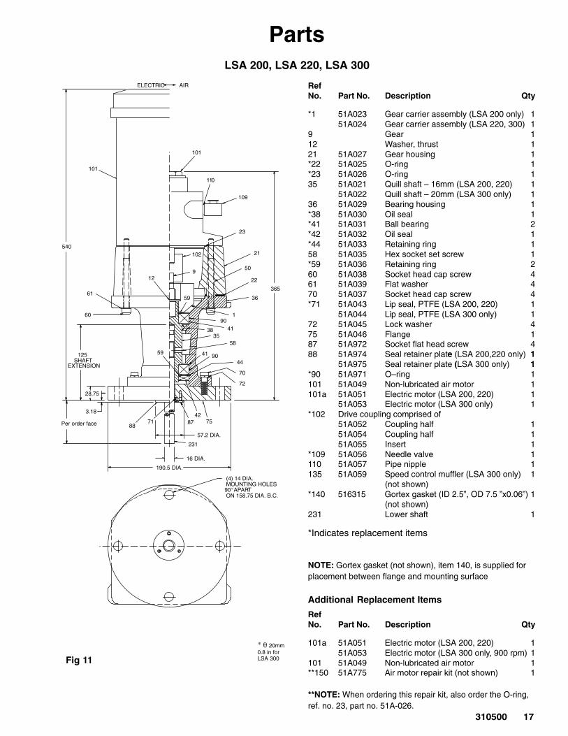
PartsLSA 200, LSA 220, LSA 300
Fig 11
Per order face
� � 20mm 0.8 in forLSA 300
125SHAFT
EXTENSION
(4) 14 DIA.MOUNTING HOLES
APARTON 158.75 DIA. B.C.
ELECTRIC AIR
101
101
109
110
23
21
22
36
9
102
1
413835
58
41 9044
70
72
8742
75
231
7188
3.18
28.75
540
365
57.2 DIA.
16 DIA.
190.5 DIA.
12
59
50
60
61
90
59
90�
RefNo. Part No. Description Qty
*1 51A023 Gear carrier assembly (LSA 200 only) 151A024 Gear carrier assembly (LSA 220, 300) 1
9 Gear 112 Washer, thrust 121 51A027 Gear housing 1*22 51A025 O-ring 1*23 51A026 O-ring 135 51A021 Quill shaft – 16mm (LSA 200, 220) 1
51A022 Quill shaft – 20mm (LSA 300 only) 136 51A029 Bearing housing 1*38 51A030 Oil seal 1*41 51A031 Ball bearing 2*42 51A032 Oil seal 1*44 51A033 Retaining ring 158 51A035 Hex socket set screw 1*59 51A036 Retaining ring 260 51A038 Socket head cap screw 461 51A039 Flat washer 470 51A037 Socket head cap screw 4*71 51A043 Lip seal, PTFE (LSA 200, 220) 1
51A044 Lip seal, PTFE (LSA 300 only) 172 51A045 Lock washer 475 51A046 Flange 187 51A972 Socket flat head screw 488 51A974 Seal retainer plate (LSA 200,220 only) 1
51A975 Seal retainer plate (LSA 300 only) 1*90 51A971 O–ring 1101 51A049 Non-lubricated air motor 1101a 51A051 Electric motor (LSA 200, 220) 1
51A053 Electric motor (LSA 300 only) 1*102 Drive coupling comprised of
51A052 Coupling half 151A054 Coupling half 151A055 Insert 1
*109 51A056 Needle valve 1110 51A057 Pipe nipple 1135 51A059 Speed control muffler (LSA 300 only) 1
(not shown)*140 516315 Gortex gasket (ID 2.5”, OD 7.5 ”x0.06”) 1
(not shown)231 Lower shaft 1
*Indicates replacement items
NOTE: Gortex gasket (not shown), item 140, is supplied forplacement between flange and mounting surface
Additional Replacement Items
RefNo. Part No. Description Qty
101a 51A051 Electric motor (LSA 200, 220) 151A053 Electric motor (LSA 300 only, 900 rpm) 1
101 51A049 Non-lubricated air motor 1**150 51A775 Air motor repair kit (not shown) 1
**NOTE: When ordering this repair kit, also order the O-ring,ref. no. 23, part no. 51A-026.
� ������
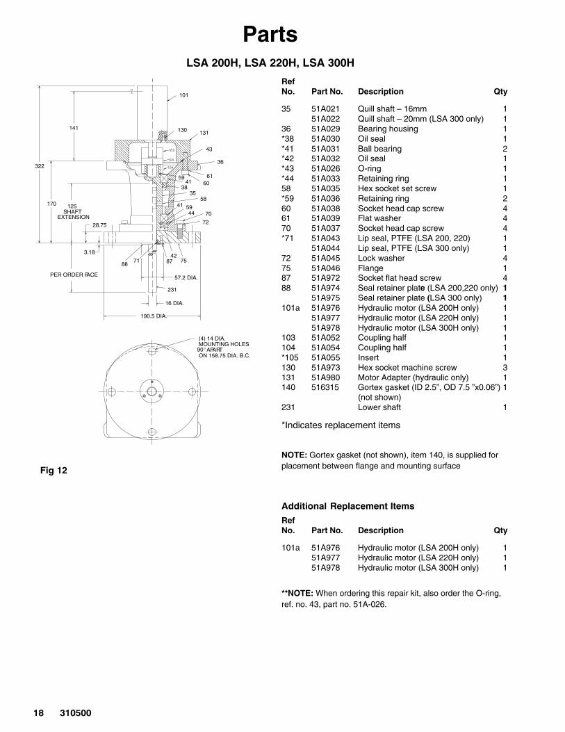
PartsLSA 200H, LSA 220H, LSA 300H
Fig 12
125SHAFT
EXTENSION
(4) 14 DIA.MOUNTING HOLES
APARTON 158.75 DIA. B.C.
PER ORDER FACE
3.18
28.75
170
57.2 DIA.
16 DIA.
190.5 DIA.
101
130 131
43
36
6160
5941
3835
5841 59
44 70
72
71 7542
87
322
141
88
231
� �
RefNo. Part No. Description Qty
35 51A021 Quill shaft – 16mm 151A022 Quill shaft – 20mm (LSA 300 only) 1
36 51A029 Bearing housing 1*38 51A030 Oil seal 1*41 51A031 Ball bearing 2*42 51A032 Oil seal 1*43 51A026 O-ring 1*44 51A033 Retaining ring 158 51A035 Hex socket set screw 1*59 51A036 Retaining ring 260 51A038 Socket head cap screw 461 51A039 Flat washer 470 51A037 Socket head cap screw 4*71 51A043 Lip seal, PTFE (LSA 200, 220) 1
51A044 Lip seal, PTFE (LSA 300 only) 172 51A045 Lock washer 475 51A046 Flange 187 51A972 Socket flat head screw 488 51A974 Seal retainer plate (LSA 200,220 only) 1
51A975 Seal retainer plate (LSA 300 only) 1101a 51A976 Hydraulic motor (LSA 200H only) 1
51A977 Hydraulic motor (LSA 220H only) 151A978 Hydraulic motor (LSA 300H only) 1
103 51A052 Coupling half 1104 51A054 Coupling half 1*105 51A055 Insert 1130 51A973 Hex socket machine screw 3131 51A980 Motor Adapter (hydraulic only) 1140 516315 Gortex gasket (ID 2.5”, OD 7.5 ”x0.06”) 1
(not shown)231 Lower shaft 1
*Indicates replacement items
NOTE: Gortex gasket (not shown), item 140, is supplied forplacement between flange and mounting surface
Additional Replacement Items
RefNo. Part No. Description Qty
101a 51A976 Hydraulic motor (LSA 200H only) 151A977 Hydraulic motor (LSA 220H only) 151A978 Hydraulic motor (LSA 300H only) 1
**NOTE: When ordering this repair kit, also order the O-ring,ref. no. 43, part no. 51A-026.
��������
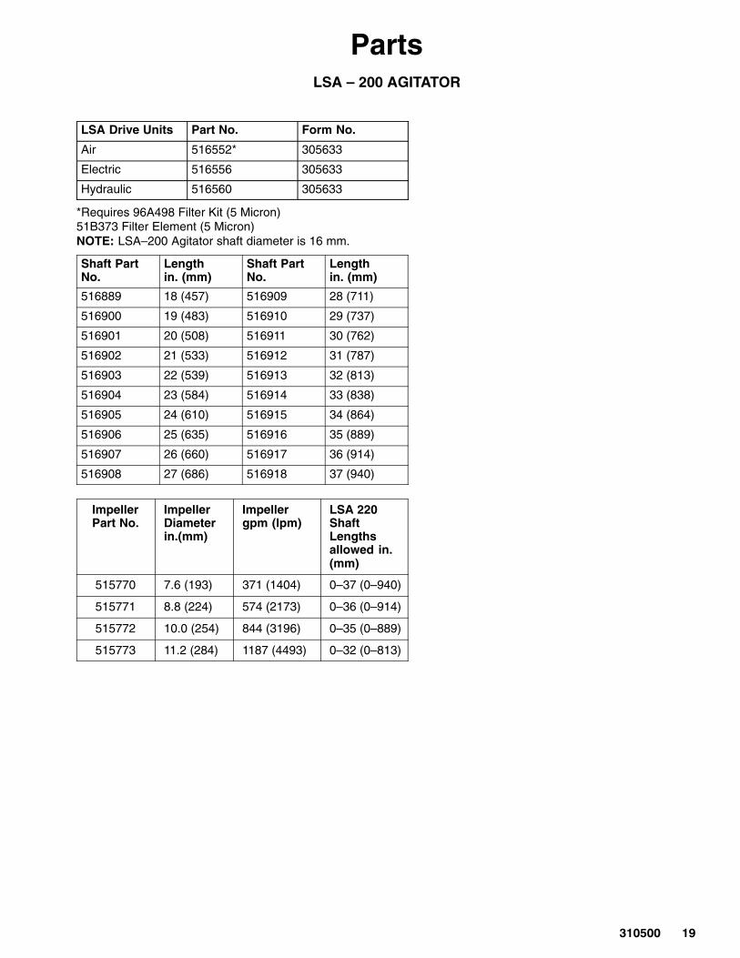
PartsLSA – 200 AGITATOR
LSA Drive Units Part No. Form No.
Air 516552* 305633
Electric 516556 305633
Hydraulic 516560 305633
*Requires 96A498 Filter Kit (5 Micron)51B373 Filter Element (5 Micron)NOTE: LSA–200 Agitator shaft diameter is 16 mm.
Shaft PartNo.
Lengthin. (mm)
Shaft PartNo.
Lengthin. (mm)
516889 18 (457) 516909 28 (711)
516900 19 (483) 516910 29 (737)
516901 20 (508) 516911 30 (762)
516902 21 (533) 516912 31 (787)
516903 22 (539) 516913 32 (813)
516904 23 (584) 516914 33 (838)
516905 24 (610) 516915 34 (864)
516906 25 (635) 516916 35 (889)
516907 26 (660) 516917 36 (914)
516908 27 (686) 516918 37 (940)
ImpellerPart No.
ImpellerDiameterin.(mm)
Impellergpm (lpm)
LSA 220ShaftLengths allowed in.(mm)
515770 7.6 (193) 371 (1404) 0–37 (0–940)
515771 8.8 (224) 574 (2173) 0–36 (0–914)
515772 10.0 (254) 844 (3196) 0–35 (0–889)
515773 11.2 (284) 1187 (4493) 0–32 (0–813)
�� ������
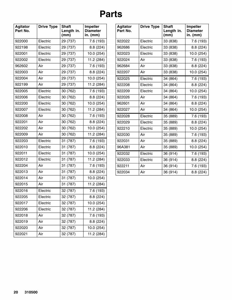
PartsAgitatorPart No.
Drive Type ShaftLength in.(mm)
ImpellerDiameterin. (mm)
922000 Electric 29 (737) 7.6 (193)
922198 Electric 29 (737) 8.8 (224)
922001 Electric 29 (737) 10.0 (254)
922002 Electric 29 (737) 11.2 (284)
962602 Air 29 (737) 7.6 (193)
922003 Air 29 (737) 8.8 (224)
922004 Air 29 (737) 10.0 (254)
922199 Air 29 (737) 11.2 (284)
922005 Electric 30 (762) 7.6 (193)
922006 Electric 30 (762) 8.8 (224)
922200 Electric 30 (762) 10.0 (254)
922007 Electric 30 (762) 11.2 (284)
922008 Air 30 (762) 7.6 (193)
922201 Air 30 (762) 8.8 (224)
922202 Air 30 (762) 10.0 (254)
922009 Air 30 (762) 11.2 (284)
922203 Electric 31 (787) 7.6 (193)
922010 Electric 31 (787) 8.8 (224)
922011 Electric 31 (787) 10.0 (254)
922012 Electric 31 (787) 11.2 (284)
922204 Air 31 (787) 7.6 (193)
922013 Air 31 (787) 8.8 (224)
922014 Air 31 (787) 10.0 (254)
922015 Air 31 (787) 11.2 (284)
922016 Electric 32 (787) 7.6 (193)
922205 Electric 32 (787) 8.8 (224)
922017 Electric 32 (787) 10.0 (254)
922206 Electric 32 (787) 11.2 (284)
922018 Air 32 (787) 7.6 (193)
922019 Air 32 (787) 8.8 (224)
922020 Air 32 (787) 10.0 (254)
922021 Air 32 (787) 11.2 (284)
AgitatorPart No.
Drive Type ShaftLength in.(mm)
ImpellerDiameterin. (mm)
922022 Electric 33 (838) 7.6 (193)
962686 Electric 33 (838) 8.8 (224)
922023 Electric 33 (838) 10.0 (254)
922024 Air 33 (838) 7.6 (193)
962684 Air 33 (838) 8.8 (224)
922207 Air 33 (838) 10.0 (254)
922025 Electric 34 (864) 7.6 (193)
922208 Electric 34 (864) 8.8 (224)
922209 Electric 34 (864) 10.0 (254)
922026 Air 34 (864) 7.6 (193)
962601 Air 34 (864) 8.8 (224)
922027 Air 34 (864) 10.0 (254)
922028 Electric 35 (889) 7.6 (193)
922029 Electric 35 (889) 8.8 (224)
922210 Electric 35 (889) 10.0 (254)
922030 Air 35 (889) 7.6 (193)
922031 Air 35 (889) 8.8 (224)
96A381 Air 35 (889) 10.0 (254)
922032 Electric 36 (914) 7.6 (193)
922033 Electric 36 (914) 8.8 (224)
922211 Air 36 (914) 7.6 (193)
922034 Air 36 (914) 8.8 (224)
��������
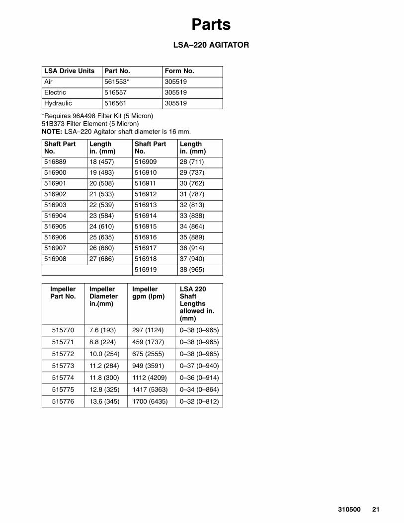
PartsLSA–220 AGITATOR
LSA Drive Units Part No. Form No.
Air 561553* 305519
Electric 516557 305519
Hydraulic 516561 305519
*Requires 96A498 Filter Kit (5 Micron)51B373 Filter Element (5 Micron)NOTE: LSA–220 Agitator shaft diameter is 16 mm.
Shaft PartNo.
Lengthin. (mm)
Shaft PartNo.
Lengthin. (mm)
516889 18 (457) 516909 28 (711)
516900 19 (483) 516910 29 (737)
516901 20 (508) 516911 30 (762)
516902 21 (533) 516912 31 (787)
516903 22 (539) 516913 32 (813)
516904 23 (584) 516914 33 (838)
516905 24 (610) 516915 34 (864)
516906 25 (635) 516916 35 (889)
516907 26 (660) 516917 36 (914)
516908 27 (686) 516918 37 (940)
516919 38 (965)
ImpellerPart No.
ImpellerDiameterin.(mm)
Impellergpm (lpm)
LSA 220ShaftLengths allowed in.(mm)
515770 7.6 (193) 297 (1124) 0–38 (0–965)
515771 8.8 (224) 459 (1737) 0–38 (0–965)
515772 10.0 (254) 675 (2555) 0–38 (0–965)
515773 11.2 (284) 949 (3591) 0–37 (0–940)
515774 11.8 (300) 1112 (4209) 0–36 (0–914)
515775 12.8 (325) 1417 (5363) 0–34 (0–864)
515776 13.6 (345) 1700 (6435) 0–32 (0–812)
�� ������
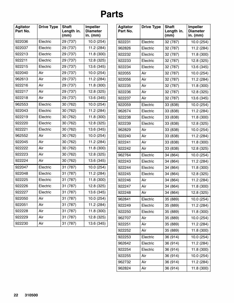
PartsAgitatorPart No.
Drive Type ShaftLength in.(mm)
ImpellerDiameterin. (mm)
922036 Electric 29 (737) 10.0 (254)
922037 Electric 29 (737) 11.2 (284)
922213 Electric 29 (737) 11.8 (300)
922211 Electric 29 (737) 12.8 (325)
922215 Electric 29 (737) 13.6 (345)
922040 Air 29 (737) 10.0 (254)
962613 Air 29 (737) 11.2 (284)
922216 Air 29 (737) 11.8 (300)
922217 Air 29 (737) 12.8 (325)
922218 Air 29 (737) 13.6 (345)
962553 Electric 30 (762) 10.0 (254)
922043 Electric 30 (762) 11.2 (284)
922219 Electric 30 (762) 11.8 (300)
922220 Electric 30 (762) 12.8 (325)
922221 Electric 30 (762) 13.6 (345)
962552 Air 30 (762) 10.0 (254)
922045 Air 30 (762) 11.2 (284)
922222 Air 30 (762) 11.8 (300)
922223 Air 30 (762) 12.8 (325)
922224 Air 30 (762) 13.6 (345)
922047 Electric 31 (787) 10.0 (254)
922048 Electric 31 (787) 11.2 (284)
922225 Electric 31 (787) 11.8 (300)
922226 Electric 31 (787) 12.8 (325)
922227 Electric 31 (787) 13.6 (345)
922050 Air 31 (787) 10.0 (254)
922051 Air 31 (787) 11.2 (284)
922228 Air 31 (787) 11.8 (300)
922229 Air 31 (787) 12.8 (325)
922230 Air 31 (787) 13.6 (345)
AgitatorPart No.
Drive Type ShaftLength in.(mm)
ImpellerDiameterin. (mm)
922231 Electric 32 (787) 10.0 (254)
962826 Electric 32 (787) 11.2 (284)
922232 Electric 32 (787) 11.8 (300)
922233 Electric 32 (787) 12.8 (325)
922234 Electric 32 (787) 13.6 (345)
922055 Air 32 (787) 10.0 (254)
922056 Air 32 (787) 11.2 (284)
922235 Air 32 (787) 11.8 (300)
922236 Air 32 (787) 12.8 (325)
922237 Air 32 (787) 13.6 (345)
922059 Electric 33 (838) 10.0 (254)
962674 Electric 33 (838) 11.2 (284)
922238 Electric 33 (838) 11.8 (300)
922239 Electric 33 (838) 12.8 (325)
962829 Air 33 (838) 10.0 (254)
922240 Air 33 (838) 11.2 (284)
922241 Air 33 (838) 11.8 (300)
922242 Air 33 (838) 12.8 (325)
962764 Electric 34 (864) 10.0 (254)
922243 Electric 34 (864) 11.2 (284)
922244 Electric 34 (864) 11.8 (300)
922245 Electric 34 (864) 12.8 (325)
922246 Air 34 (864) 11.2 (284)
922247 Air 34 (864) 11.8 (300)
922248 Air 34 (864) 12.8 (325)
962841 Electric 35 (889) 10.0 (254)
922249 Electric 35 (889) 11.2 (284)
922250 Electric 35 (889) 11.8 (300)
962707 Air 35 (889) 10.0 (254)
922251 Air 35 (889) 11.2 (284)
922252 Air 35 (889) 11.8 (300)
922253 Electric 36 (914) 10.0 (254)
962642 Electric 36 (914) 11.2 (284)
922254 Electric 36 (914) 11.8 (300)
922255 Air 36 (914) 10.0 (254)
962732 Air 36 (914) 11.2 (284)
962824 Air 36 (914) 11.8 (300)
��������
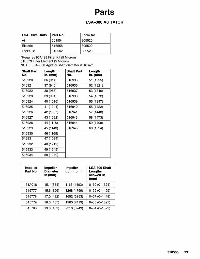
PartsLSA–300 AGITATOR
LSA Drive Units Part No. Form No.
Air 561554 305520
Electric 516558 305520
Hydraulic 516562 305520
*Requires 96A498 Filter Kit (5 Micron)51B373 Filter Element (5 Micron)NOTE: LSA–300 Agitator shaft diameter is 16 mm.
Shaft PartNo.
Lengthin. (mm)
Shaft PartNo.
Lengthin. (mm)
516920 36 (914) 516935 51 (1295)
516921 37 (940) 516936 52 (1321)
516922 38 (965) 516937 53 (1346)
516923 39 (991) 516938 54 (1372)
516924 40 (1016) 516939 55 (1397)
516925 41 (1041) 516940 55 (1422)
516926 42 (1067) 516941 57 (1448)
516927 43 (1092) 516943 58 (1473)
516928 44 (1118) 516944 59 (1499)
516929 45 (1143) 516945 60 (1524)
516930 46 (1168)
516931 47 (1094)
516932 48 (1219)
516933 49 (1245)
516934 50 (1270)
ImpellerPart No.
ImpellerDiameterin.(mm)
Impellergpm (lpm)
LSA 300 ShaftLengths allowed in.(mm)
51A018 15.1 (384) 1163 (4402) 0–60 (0–1524)
515777 15.6 (396) 1268 (4799) 0–59 (0–1499)
515778 17.0 (432) 1652 (6253) 0–57 (0–1448)
515779 18.0 (457) 1960 (7419) 0–55 (0–1397)
515780 19.0 (483) 2310 (8743) 0–54 (0–1372)
�� ������
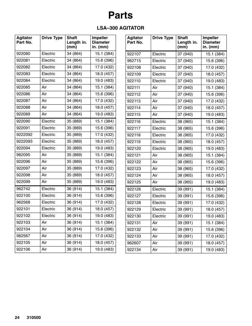
PartsLSA–300 AGITATOR
AgitatorPart No.
Drive Type ShaftLength in.(mm)
ImpellerDiameterin. (mm)
922080 Electric 34 (864) 15.1 (384)
922081 Electric 34 (864) 15.6 (396)
922082 Electric 34 (864) 17.0 (432)
922083 Electric 34 (864) 18.0 (457)
922084 Electric 34 (864) 19.0 (483)
922085 Air 34 (864) 15.1 (384)
922086 Air 34 (864) 15.6 (396)
922087 Air 34 (864) 17.0 (432)
922088 Air 34 (864) 18.0 (457)
922089 Air 34 (864) 19.0 (483)
922090 Electric 35 (889) 15.1 (384)
922091 Electric 35 (889) 15.6 (396)
9222092 Electric 35 (889) 17.0 (432)
9222093 Electric 35 (889) 18.0 (457)
922094 Electric 35 (889) 19.0 (483)
962095 Air 35 (889) 15.1 (384)
922096 Air 35 (889) 15.6 (396)
922097 Air 35 (889) 17.0 (432)
922098 Air 35 (889) 18.0 (457)
922099 Air 35 (889) 19.0 (483)
962742 Electric 36 (914) 15.1 (384)
922100 Electric 36 (914) 15.6 (396)
962568 Electric 36 (914) 17.0 (432)
922101 Electric 36 (914) 18.0 (457)
922102 Electric 36 (914) 19.0 (483)
922103 Air 36 (914) 15.1 (384)
922104 Air 36 (914) 15.6 (396)
962567 Air 36 (914) 17.0 (432)
922105 Air 36 (914) 18.0 (457)
922106 Air 36 (914) 19.0 (483)
AgitatorPart No.
Drive Type ShaftLength in.(mm)
ImpellerDiameterin. (mm)
922107 Electric 37 (940) 15.1 (384)
962715 Electric 37 (940) 15.6 (396)
922108 Electric 37 (940) 17.0 (432)
922109 Electric 37 (940) 18.0 (457)
922110 Electric 37 (940) 19.0 (483)
922111 Air 37 (940) 15.1 (384)
922112 Air 37 (940) 15.6 (396)
922113 Air 37 (940) 17.0 (432)
922114 Air 37 (940) 18.0 (457)
922115 Air 37 (940) 19.0 (483)
922116 Electric 38 (965) 15.1 (384)
922117 Electric 38 (965) 15.6 (396)
922118 Electric 38 (965) 17.0 (432)
922119 Electric 38 (965) 18.0 (457)
922120 Electric 38 (965) 19.0 (483)
922121 Air 38 (965) 15.1 (384)
922122 Air 38 (965) 15.6 (396)
922123 Air 38 (965) 17.0 (432)
922124 Air 38 (965) 18.0 (457)
922125 Air 38 (965) 19.0 (483)
922126 Electric 39 (991) 15.1 (384)
922127 Electric 39 (991) 15.6 (396)
922128 Electric 39 (991) 17.0 (432)
922129 Electric 39 (991) 18.0 (457)
922130 Electric 39 (991) 19.0 (483)
922131 Air 39 (991) 15.1 (384)
922132 Air 39 (991) 15.6 (396)
922133 Air 39 (991) 17.0 (432)
962607 Air 39 (991) 18.0 (457)
922134 Air 39 (991) 19.0 (483)
��������
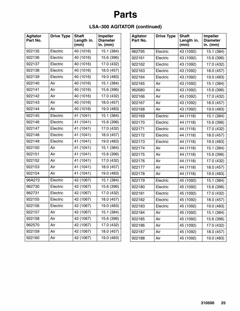
PartsLSA–300 AGITATOR (continued)
AgitatorPart No.
Drive Type ShaftLength in.(mm)
ImpellerDiameterin. (mm)
922135 Electric 40 (1016) 15.1 (384)
922136 Electric 40 (1016) 15.6 (396)
922137 Electric 40 (1016) 17.0 (432)
922138 Electric 40 (1016) 18.0 (457)
922139 Electric 40 (1016) 19.0 (483)
922140 Air 40 (1016) 15.1 (384)
922141 Air 40 (1016) 15.6 (396)
922142 Air 40 (1016) 17.0 (432)
922143 Air 40 (1016) 18.0 (457)
922144 Air 40 (1016) 19.0 (483)
922145 Electric 41 (1041) 15.1 (384)
922146 Electric 41 (1041) 15.6 (396)
922147 Electric 41 (1041) 17.0 (432)
922148 Electric 41 (1041) 18.0 (457)
922149 Electric 41 (1041) 19.0 (483)
922150 Air 41 (1041) 15.1 (384)
922151 Air 41 (1041) 15.6 (396)
922152 Air 41 (1041) 17.0 (432)
922153 Air 41 (1041) 18.0 (457)
922154 Air 41 (1041) 19.0 (483)
96A272 Electric 42 (1067) 15.1 (384)
962730 Electric 42 (1067) 15.6 (396)
962731 Electric 42 (1067) 17.0 (432)
922155 Electric 42 (1067) 18.0 (457)
922156 Electric 42 (1067) 19.0 (483)
922157 Air 42 (1067) 15.1 (384)
922158 Air 42 (1067) 15.6 (396)
962570 Air 42 (1067) 17.0 (432)
922159 Air 42 (1067) 18.0 (457)
922160 Air 42 (1067) 19.0 (483)
AgitatorPart No.
Drive Type ShaftLength in.(mm)
ImpellerDiameterin. (mm)
962795 Electric 43 (1092) 15.1 (384)
922161 Electric 43 (1092) 15.6 (396)
922162 Electric 43 (1092) 17.0 (432)
922163 Electric 43 (1092) 18.0 (457)
922164 Electric 43 (1092) 19.0 (483)
922165 Air 43 (1092) 15.1 (384)
962680 Air 43 (1092) 15.6 (396)
922166 Air 43 (1092) 17.0 (432)
922167 Air 43 (1092) 18.0 (457)
922168 Air 43 (1092) 19.0 (483)
922169 Electric 44 (1118) 15.1 (384)
922170 Electric 44 (1118) 15.6 (396)
922171 Electric 44 (1118) 17.0 (432)
922172 Electric 44 (1118) 18.0 (457)
922173 Electric 44 (1118) 19.0 (483)
922174 Air 44 (1118) 15.1 (384)
922175 Air 44 (1118) 15.6 (396)
922176 Air 44 (1118) 17.0 (432)
922177 Air 44 (1118) 18.0 (457)
922178 Air 44 (1118) 19.0 (483)
922179 Electric 45 (1092) 15.1 (384)
922180 Electric 45 (1092) 15.6 (396)
922181 Electric 45 (1092) 17.0 (432)
922182 Electric 45 (1092) 18.0 (457)
922183 Electric 45 (1092) 19.0 (483)
922184 Air 45 (1092) 15.1 (384)
922185 Air 45 (1092) 15.6 (396)
922186 Air 45 (1092) 17.0 (432)
922187 Air 45 (1092) 18.0 (457)
922188 Air 45 (1092) 19.0 (483)
�� ������
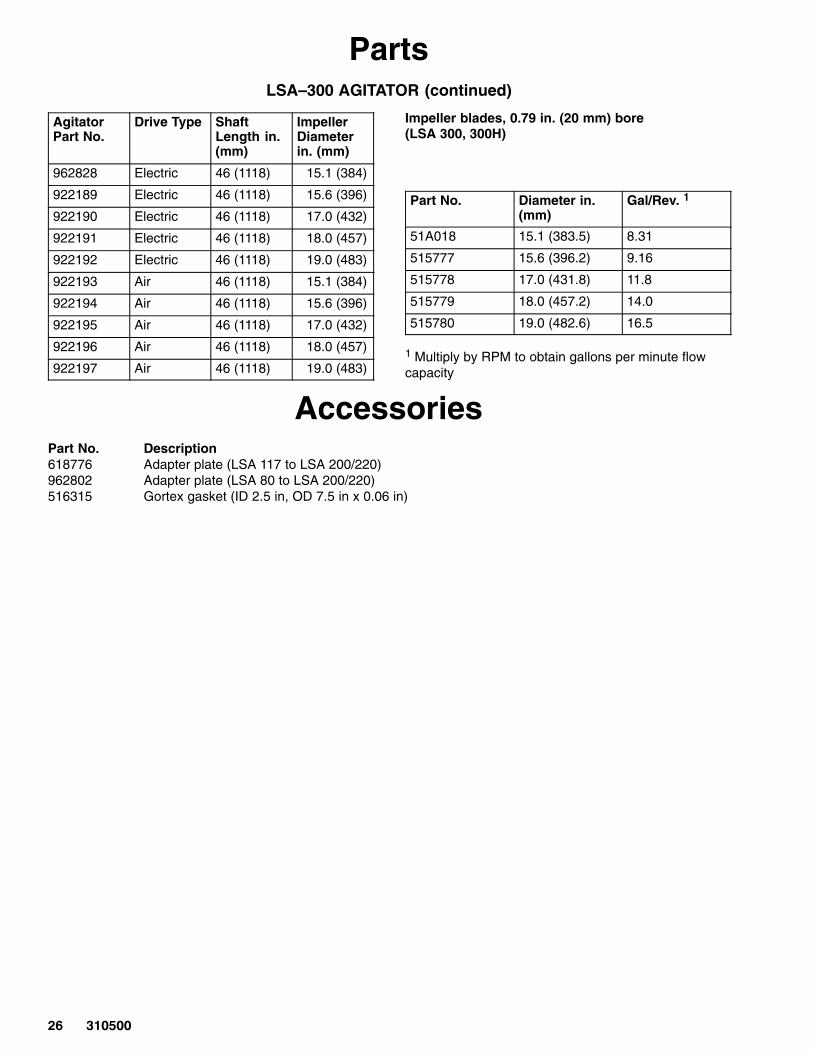
PartsLSA–300 AGITATOR (continued)
AgitatorPart No.
Drive Type ShaftLength in.(mm)
ImpellerDiameterin. (mm)
962828 Electric 46 (1118) 15.1 (384)
922189 Electric 46 (1118) 15.6 (396)
922190 Electric 46 (1118) 17.0 (432)
922191 Electric 46 (1118) 18.0 (457)
922192 Electric 46 (1118) 19.0 (483)
922193 Air 46 (1118) 15.1 (384)
922194 Air 46 (1118) 15.6 (396)
922195 Air 46 (1118) 17.0 (432)
922196 Air 46 (1118) 18.0 (457)
922197 Air 46 (1118) 19.0 (483)
Impeller blades, 0.79 in. (20 mm) bore(LSA 300, 300H)
Part No. Diameter in.(mm)
Gal/Rev. 1
51A018 15.1 (383.5) 8.31
515777 15.6 (396.2) 9.16
515778 17.0 (431.8) 11.8
515779 18.0 (457.2) 14.0
515780 19.0 (482.6) 16.5
1 Multiply by RPM to obtain gallons per minute flowcapacity
AccessoriesPart No. Description618776 Adapter plate (LSA 117 to LSA 200/220)962802 Adapter plate (LSA 80 to LSA 200/220)516315 Gortex gasket (ID 2.5 in, OD 7.5 in x 0.06 in)
��������
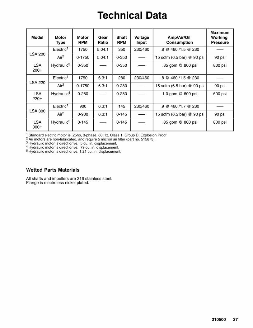
Technical Data
Model MotorType
MotorRPM
GearRatio
ShaftRPM
VoltageInput
Amp/Air/Oil Consumption
MaximumWorking Pressure
LSA 200Electric1 1750 5.04:1 350 230/460 .8 @ 460 /1.5 @ 230 –––
LSA 200Air2 0-1750 5.04:1 0-350 ––– 15 scfm (6.5 bar) @ 90 psi 90 psi
LSA200H
Hydraulic3 0-350 ––– 0-350 ––– .85 gpm @ 800 psi 800 psi
LSA 220Electric1 1750 6.3:1 280 230/460 .8 @ 460 /1.5 @ 230 –––
LSA 220Air2 0-1750 6.3:1 0-280 ––– 15 scfm (6.5 bar) @ 90 psi 90 psi
LSA220H
Hydraulic4 0-280 ––– 0-280 ––– 1.0 gpm @ 600 psi 600 psi
LSA 300Electric1 900 6.3:1 145 230/460 .9 @ 460 /1.7 @ 230 –––
LSA 300Air2 0-900 6.3:1 0-145 ––– 15 scfm (6.5 bar) @ 90 psi 90 psi
LSA300H
Hydraulic5 0-145 ––– 0-145 ––– .85 gpm @ 800 psi 800 psi
1 Standard electric motor is .25hp, 3-phase, 60 Hz, Class 1, Group D, Explosion Proof2 Air motors are non-lubricated, and require 5 micron air filter (part no. 515873).3 Hydraulic motor is direct drive, .5 cu. in. displacement.4 Hydraulic motor is direct drive, .79 cu. in. displacement.5 Hydraulic motor is direct drive, 1.21 cu. in. displacement.
Wetted Parts Materials
All shafts and impellers are 316 stainless steel.Flange is electroless nickel plated.
� ������
Graco Standard WarrantyGraco warrants all equipment manufactured by Graco and bearing its name to be free from defects in material and workmanship on thedate of sale to the original purchaser for use. With the exception of any special, extended, or limited warranty published by Graco,Graco will, for a period of twelve months from the date of sale, repair or replace any part of the equipment determined by Graco to bedefective. This warranty applies only when the equipment is installed, operated and maintained in accordance with Graco’s writtenrecommendations.
This warranty does not cover, and Graco shall not be liable for general wear and tear, or any malfunction, damage or wear caused byfaulty installation, misapplication, abrasion, corrosion, inadequate or improper maintenance, negligence, accident, tampering, or sub-stitution of non–Graco component parts. Nor shall Graco be liable for malfunction, damage or wear caused by the incompatibility ofGraco equipment with structures, accessories, equipment or materials not supplied by Graco, or the improper design, manufacture,installation, operation or maintenance of structures, accessories, equipment or materials not supplied by Graco.
This warranty is conditioned upon the prepaid return of the equipment claimed to be defective to an authorized Graco distributor forverification of the claimed defect. If the claimed defect is verified, Graco will repair or replace free of charge any defective parts. Theequipment will be returned to the original purchaser transportation prepaid. If inspection of the equipment does not disclose any defectin material or workmanship, repairs will be made at a reasonable charge, which charges may include the costs of parts, labor, andtransportation.
THIS WARRANTY IS EXCLUSIVE, AND IS IN LIEU OF ANY OTHER WARRANTIES, EXPRESS OR IMPLIED, INCLUDING BUTNOT LIMITED TO WARRANTY OF MERCHANTABILITY OR WARRANTY OF FITNESS FOR A PARTICULAR PURPOSE.
Graco’s sole obligation and buyer’s sole remedy for any breach of warranty shall be as set forth above. The buyer agrees that no otherremedy (including, but not limited to, incidental or consequential damages for lost profits, lost sales, injury to person or property, or anyother incidental or consequential loss) shall be available. Any action for breach of warranty must be brought within two (2) years of thedate of sale.
Graco makes no warranty, and disclaims all implied warranties of merchantability and fitness for a particular purpose in connectionwith accessories, equipment, materials or components sold but not manufactured by Graco. These items sold, but not manufacturedby Graco (such as electric motors, switches, hose, etc.), are subject to the warranty, if any, of their manufacturer. Graco will providepurchaser with reasonable assistance in making any claim for breach of these warranties.
In no event will Graco be liable for indirect, incidental, special or consequential damages resulting from Graco supplying equipmenthereunder, or the furnishing, performance, or use of any products or other goods sold hereto, whether due to a breach of contract,breach of warranty, the negligence of Graco, or otherwise.
FOR GRACO CANADA CUSTOMERSThe parties acknowledge that they have required that the present document, as well as all documents, notices and legal proceedingsentered into, given or instituted pursuant hereto or relating directly or indirectly hereto, be drawn up in English. Les parties reconnais-sent avoir convenu que la rédaction du présente document sera en Anglais, ainsi que tous documents, avis et procédures judiciairesexécutés, donnés ou intentés à la suite de ou en rapport, directement ou indirectement, avec les procedures concernées.
Graco Information
TO PLACE AN ORDER, contact your Graco distributor, or call one of the following numbers to identify the distributor closest to you:
1–800–328–0211 Toll Free612–623–6921
612–378–3505 Fax
All written and visual data contained in this document reflects the latest product information available at the time of publication.Graco reserves the right to make changes at any time without notice.
MM 310500
Graco Headquarters: MinneapolisInternational Offices: Belgium, China, Japan, Korea
������� �!���"!�!�#�$���������� %�"��&'�� ��������(����www.graco.com
PRINTED IN USA 310500 02/2000, Revised 05/2005