Embed Size (px)
Citation preview


NO.SHEET
BRIDGE PLANS ID
REV.
REV.
REV.
REVIEWED
QUAN.
DR.
DES.
BY CHK. DATE
COUNTY ROUTE
SOUTH CAROLINASPARTANBURG COUNTY
GENERAL BRIDGE LAYOUT
FL
OW
PLAN
SCALE: 1" = 5'-0"
TO NEW CUT ROAD
TO CAMPOBELLO
MO
TL
OW
CR
EE
K
TRIB
UT
AR
Y
TO
BR0012 S-1
SPARTANBURG
880
890
18+00 18+7518+5018+25
885
895
900
890
885
895
900
3.22%4.00%
L= 355.00
EL = 891.52
PI= 18+55.00
GRADE DATA -L-
EXIST. GROUND
ABUTMENT 1
ABUTMENT 2
GRADE
PROFILE
PROPOSED
15'-0"
15'-0"
-L- STA. 18+10.98
FILL APPROACH
BEGIN FLOWABLE
-L- STA. 18+87.77
FILL APPROACH
END FLOWABLE
40'-3•" (BACKWALL-TO-BACKWALL)
BE
GI
N
BRI
DG
E
EL. 894.886
ST
A. 18
+29.85
EL. 894.688
ST
A. 18
+70.15
EN
D
BRI
DG
E
BORING B-4
BORING B-3
BORING B-1
B-2
BORING
-N-
18+
00
19+
00
(100 YR.)
EL. 889.86
HIGH WATER
FILL APPROACH (TYP.)
PROPOSED FLOWABLE
895
894
893892
891
890
891
895
891
893
892
890
892893
894
894
895
896
885
884
886
887
888
889
893
891
890
889
888
887
894
895
892
889
887
2'-0" (TYP.)(
TYP.)
2'-0"
CLASS B RIP RAP (TYP.)
1
1.5
886
885
884
BOUNDARY (TYP.)
DELINEATED WETLAND
FIX EXP.
MATERIAL (TYP.)
GEOTEXTILE BEDDING
MOTLOW CREEK RD
2'-0"2'-0"
SCALE: 1" = 5'-0"
SECTION ALONG C -L-L
SEE ROADWAY PLANS
PAVEMENT TRANSITION (TYP.)
423 467 8401
865 546 5800
606 248 6600
Tri-Cities, TN
Knoxville, TN
Middlesboro, KY
Charleston, SC
843 974 5650
Atlanta, GA
770 627 3509
cCopyright 2006 Vaughn & Melton, Inc. All Rights Reserved
Consulting Engineers
Boone, NC
828 355 9933
704 357 0488
Charlotte, NC
919 977 9455
Raleigh, NC
828 253 2796
Asheville, NC
Spartanburg,South Carolina
864 574 4775
INDEX OF SHEETS
N8° 0' 58"W
HYDROLOGY DATA:
~
Probability 0.5%
Q = 2,690
OVERTOPPING FLOOD:
NOTE: Data from Bridge Section
100-Year H.W. Elev. = 889.86
Vel.100 = 8.18 ft/s
Q100 = 1,200 cfs
25-Year H.W. Elev. = 888.83 ft.
Vel.25 = 6.81 ft/s
Q25 = 840 cfs
D.A. = 2.1 sq. mi. = 1,344 ac.
(
TY
P.)
15'-0"
(
TY
P.)
15'-0"
(T
YP.)
6%
SU
PE
RE
LE
VA
TIO
N D = 11º 27' 33"
L = 826.24'
PI = 18+18.16
T = 542.60'
E = 237.85'
R = 500.00'
-L- CURVE DATA
A
I
N
HT
O
UL
ROCA
S
.
E
A
T
J
RRY CAR
ER
No. 19170
RE
EN
IG
NE
LA
NOISSEFOR
P
DE
RE
TS
IG
ER
LC
LC -L-
LC
DETAIL, SHEET S-3 (TYP.)
SEE PIPE UNDERDRAIN
(MOTLOW CREEK ROAD)
-L-
-L- STA. 18+70.15
CORED SLAB BRIDGE
END PROPOSED
W.P. #2
-L- STA. 18+29.85
CORED SLAB BRIDGE
BEGIN PROPOSED
W.P. #1
= 94º 40' 47" (LT) D
PRESTRESSED CONCRETE CORED SLAB DETAILSS-21
PRESTRESSED CONCRETE CORED SLAB DETAILSS-20
PRESTRESSED CONCRETE CORED SLAB DETAILSS-19
S-18 PRESTRESSED CONCRETE CORED SLAB DETAILS
40'-0" PRESTRESSED CONC. CORED SLAB PLAN (60° SKEW)S-17
SUBSTRUCTURE BILL OF MATERIALS-16
WINGWALL SECTIONSS-15
ABUTMENT 2 WING DETAILSS-14
ABUTMENT 1 WING DETAILSS-13
ABUTMENT SECTIONSS-12
ABUTMENT 2S-11
ABUTMENT 1S-10
FOOTING REINFORCING PLANS - ABUTMENT 2S-9
FOOTING REINFORCING PLANS - ABUTMENT 1S-8
FOUNDATION LAYOUTS-7
BORING LOGS (2 OF 2)S-6
BORING LOGS (1 OF 2)S-5
REINFORCING BENDING DETAILSS-4
S-3 DRAINAGE DETAILS
GENERAL NOTES & BRIDGE QUANTITIESS-2
GENERAL BRIDGE LAYOUTS-1
BRIDGE CHORD
BRIDGE/
(TYP.)
TO BRIDGE CHORD
60°00' 00"
27'-6"
(
CL
EA
R
RO
AD
WA
Y)
18'-10‹" 17'-7‹"
(TYP.)
SEE ROAD PLANS
PAVEMENT SECTION
FULL DEPTH
08/19
09/19
08/19
PRG RTS
PRG
RTS
RTS
HL
DocuSign Envelope ID: 720845D9-D5DF-42A4-88E0-A39F368DA2AE
10/8/2019

MATERIAL & WORKMANSHIP
COMPLETION DATES
REINFORCING STEEL
CONCRETE
WATER ELEVATIONS
PRESTRESSED CONCRETE BEAMS
EXCAVATION FOR END BENTS
DESIGN DATA
FINAL FINISH OF EXPOSED CONCRETE SURFACES
DEFLECTION & SETTLEMENTALLOWANCE FOR DEAD LOAD
SPECIFICATIONS
AND SPECIAL PROVISIONSCOORDINATION OF PLANS, SPECIFICATIONS,
D) No final surface finish required.
All Units Designated Units:
except top of bent caps and piers.
C) Entire surface of designated substructure units,
B) Outside face of exterior prestressed girders.
deck slabs and sidewalks.
and wing walls; outside vertical edge of bridge
approach slab curbs, concrete utility supports,
A) Entire surface of all barrier rails, parapet walls,
checked and designated bridge areas:
Apply the final surface finish on the bridge(s) only to the following
SOUTH CAROLINASPARTANBURG COUNTY
NO.SHEET
BRIDGE PLANS ID
S-2BR0012
REV.
REV.
REV.
REVIEWED
QUAN.
DR.
DES.
BY CHK. DATE
COUNTY ROUTE
MOTLOW CREEK RDSPARTANBURG
price bid for class of concrete specified in the Plans.
unit price bid for excavation. Include excavation above this in the unit
included for the cap and berm in the above paragraph is paid for at the
If a concrete footing is used for the end bent, the excavation below that
bent caps, in the unit price bid for class of concrete specified in the Plans.
material under superstructure to an elevation twelve inches below tops of end
Include all cost of excavation necessary to construct end bents and to remove
settlement, and vertical curve ordinates.
cambers as necessary to allow for falsework deflection, falsework
40 feet in length, unless otherwise directed by the RCE. Adjust these
slab spans 30 feet in length, and …" for concrete flat slab spans
for concrete flat slab spans 22 feet in length, ‰" for concrete flat
For instantaneous and long-time dead load deflection, use a camber of „"
grade plus the allowance for long-time deflection.
falsework the top of the structure shall conform to theoretical finished
long-time dead load deflection of the span such that on removal of the
for the instantaneous dead load deflection of the span, and for the
for the deflection of the falsework, for any settlement of the falsework,
In setting falsework for reinforced concrete spans, make an allowance
regardless of any adjustments.
(extend up into the deck past the bottom mat of reinforcing steel)
prestressed beams shall meet the requirements for a composite section
Welded studs on steel beams and reinforcing steel extending up out of
thickness or a reduction in the concrete cover over the reinforcing steel.
adjustment on partially loaded beams does not create a change in the deck
loaded beams adjacent to closure pour areas. Verify that any proposed
widening projects, consider and make adjustments as necessary for partially
Prior to making deck pours on any stage construction work, and bridge
dead load deflections.
apply an allowance to the design finished grade to compensate for computed
In setting forms for structural steel or prestressed concrete beam spans,
ANCHOR BOLTS
BEARING ASSEMBLIES
ORIENTATION IN RELATION TO STATIONING
to direction of stationing.
Left and right sides, where referred to in these plans, are in relation
in the unit price bid for reinforcing steel.
Include all costs of furnishing and installing anchor bolt assemblies
assemblies is included in the bent quantities for reinforcing steel.
AASHTO M 232 or ASTM F 2329 as applicable. The weight of anchor bolt
Galvanize all components of anchor bolt assemblies in accordance with
cost in the unit price bid for prestressed beams.
for structural steel is included in the project. Otherwise, include the
components in the lump sum price bid for structural steel if a bid item
Include all cost of furnishing and installing steel bearing assembly
ASTM A 780.
areas and/or damaged areas of the galvanized coating in accordance with
field welding of galvanized bearing assemblies, field repair the weld
with Subsection 710.4.2 of the Standard Specifications. After the required
repair the weld areas and/or any damaged areas to the paint in accordance
After the required field welding of painted bearing assemblies, field
with AASHTO M 111, AASHTO M 232, or ASTM F 2329 as applicable.
NS2 Paint System. Galvanize all other bearing assemblies in accordance
bearing assembly components from weathering steel and paint them using the
If bearing assemblies support weathering steel beams or girders, fabricate
X
CONDUIT IN BARRIER PARAPET
cement in accordance with manufacturer's recommendations.
or molded on each fittings. Connect conduit and fittings using solvent
with UL labels: Conduit - on each 10 foot length; Fittings - stamped
with NEMA TC-3 and UL standard 514B. Furnish conduit and fittings
with the NEMA TC-2 and UL standard 651 and furnish fittings in accordance
Furnish schedule 80 PVC rigid nonmetallic conduits in accordance
with the national electric code (NEC) and as directed by the RCE.
Furnish and install approved conduits and fittings in accordance
required in the unit price bid for 2" Dia. schedule 80 PVC conduit.
expansion/deflection and/or expansion fittings, and any incidentals
Include all costs for furnishing and installing conduit,
barrier parapet.
Provide expansion/deflection fittings at any open joints in the
transition and cap with watertight covers
Extend conduits 6 inches beyond each end of barrier parapet
Use Schedule 80 PVC nonmetallic pipe for conduit.
423 467 8401
865 546 5800
606 248 6600
Tri-Cities, TN
Knoxville, TN
Middlesboro, KY
Charleston, SC
843 974 5650
Atlanta, GA
770 627 3509
cCopyright 2006 Vaughn & Melton, Inc. All Rights Reserved
Consulting Engineers
Boone, NC
828 355 9933
704 357 0488
Charlotte, NC
919 977 9455
Raleigh, NC
828 253 2796
Asheville, NC
Spartanburg,South Carolina
864 574 4775
SUMMARY OF QUANTITIES
SUPERSTRUCTURE
SUBSTRUCTURE
SPAN 1
ITEM NO. 7011400
LB
70114006750278
CONDUIT
80 PVC
2.0" SCHEDULE
LF CY
CLASS 4000
STRUCTURES-
CONCRETE FOR
(BRIDGE)
FOR STRUCTURES
REINFORCING STEEL
7031200 7054008 72431007045991
CORED SLABS
3'-0" X 1'-9"
LF LF EA
BEARING
ELASTOMERIC
STRUCTUREW/ 4" PERF. FOR
UNDERDRAIN #789AGGREGATE
TON
54.7
30.2
20
63.1
53.6 12147
13362
400.0 80.0
TOTAL 25509 400.0 80.0 20 84.9
2044000
REMOVAL OF EXISTING CULVERT
existing structure location shall be graded to match existing topography.
for Highway Construction (2007), Section 202. Embankment at the
the existing structure in accordance with SCDOT Standard Specifications
Once traffic has been shifted over to the new bridge structure, remove
CY
8041020 8143000
(BRIDGE DECK)
WATERPROOFING
SY
122.2
122.2
(CLASS B)
RIP-RAP
TON
34.8
30.1
64.9
8142100
58.0
44.9
SECOND METHOD)
(SUBSTRUCTURE-
WATERPROOFING
SY
2028510
DOUBLE CULVERT
EXISTING
DISPOSAL OF
REMOVAL &
EA
1
38.2
2.4
40.6
BRIDGES
FOR
EXCAVATION
ROCK
ABUTMENT 1
ABUTMENT 2
of this structure as an allowance for a future wearing surface.
An extra dead load of 0.015 KSF is incorporated into the design
having Class "B" contact surfaces.
prestressed concrete beams, are designed as slip-critical connections
All bolted connections, except for steel diaphragm members used with
section properties.
and is not included in the slab depth used for the calculation of
The top ‚" of all concrete slabs is considered as a wearing surface
Live Load: AASHTO HL-93 or Alternate Loading
Load and Resistance Factor Design (LRFD) Method
additions and revisions as stated in the Standard Specifications.
ANSI/AASHTO/AWS D1.5 Bridge Welding Code (Latest Edition) with
Specifications for Highway Bridges", 2001 Ed. with 2002 Interims.
Interim Revisions through 2015, and the SCDOT "Seismic Design
AASHTO 2014 LRFD Bridge Design Specifications, 7th Edition, with
RIP RAP
percent may weigh less than 5 pounds.
At least 50 percent shall weigh more than 37 pounds. Approximately 10
Riprap shall be class "B" with stones weighing between 5 and 200 pounds.
BRIDGE DECK WATERPROOFING
(bridge deck waterproofing) of the standard specifications.
system shall be a prepave sheet membrane in accordance with section 814
applied prior to placing the asphalt wearing surface. The waterproofing
The top surface of the cored slabs shall have a waterproofing system
BRIDGE QUANTITIESGENERAL NOTES &160.0
160.0
2103000A
CY
38.5
38.5
77.0
7045991.GD1601 bars in concrete parapet to be included in bid for Item Number2.
A1601 bars in concrete parapet to be included in bid for Item Number 7054008.1. Note:
SLABS)
(APPROACH
FILL
FLOWABLE
2043500
BRIDGES
EXC. FOR
WET & DRY
CY
179.1
99.4
79.7
116.7
build-up level.
unless indicated otherwise in these plans. Construct the top of each
Cast build-ups and shear keys on bent caps monolithic with the cap
tolerances.
than the plan dimensions when required by reinforcing bar fabrication
The minimum acceptable concrete cover for reinforcing steel is •" less
Chamfer all exposed edges ƒ" unless otherwise noted.
adjustment is made for variation in camber.
Payment for concrete in slab is based on theoretical plan quantity. No
is allowed for the performance of this work.
is considered incidental to the Contract and no additional compensation
adjustments to the RCE for approval. All cost of performing this work
are needed. Submit beam camber measurements and any proposed field
the values shown on the Plans to aid in determining if field adjustments
falsework, measure beam cambers. Compare the measured beam cambers to
After erection of the beams and prior to the erection of the deck slab
falsework is removed.
with a non-shrink structural grout suitable for overhead repairs after
When holes are cast in beams to accommodate falsework, fill the holes
class of concrete is not specified in the contract documents.
cast-in-place structural elements, use Class 4000 concrete where the
Provide the class of concrete as noted in the contract documents. For
are cut, and for beams being on a grade.
to correct for concrete shrinkage, concrete shortening when the strands
Beam lengths given are based on horizontal span only. Increase lengths
See sheet S-17 for specified concrete strength.
Do not use lap splices in column and shaft reinforcing steel.
diameter is ± • inch.
The fabrication tolerance for out-to-out dimension of welded hoop
prestressed concrete beams.
135° hook requirement does not apply to stirrups extending from
no less than the larger of ten bar diameters or six inches. This
Provide all ties and stirrups with 135° hooks that have extensions
hoops.
Manual of Standard Practice except for ties, stirrups, and welded
Fabricate reinforcing bars in accordance with the current C.R.S.I.
Grade 60 steel shall be used.
in accordance with SCDOT Standard Drawing No. 702-305-00.
reusable/durable material that is approved by the RCE. Provide numbers
installed. Recess numbers in the concrete using numbers fabricated from
date so that it will not be covered by the guardrail connector when it is
year of completion adjacent to guardrail attachment. Place this completion
bridge and on left side barrier parapet/railing at end of bridge, place
On inside face of right side barrier parapet/railing at beginning of
conditions and seasonal fluctuations.
actual water elevation during construction may vary depending on weather
The water elevations shown in the plans are for information only and the
105.4 of the Standard Specifications.
notes on this sheet and Special Provisions govern over all. See Subsection
the Standard Specifications but the remainder of the plans govern over
Generally, in case of discrepancy, this General Notes sheet governs over
in the Special Provisions.
for Highway Construction, unless otherwise specified on the Plans or
Carolina Department of Transportation 2007 Standard Specifications
Provide all material and workmanship in accordance with the South
A
I
N
HT
O
UL
ROCA
S
.
E
A
T
J
RRY CAR
ER
No. 19170
RE
EN
IG
NE
LA
NOISSEFOR
P
DE
RE
TS
IG
ER
establish proper bearing as determined by the owner's engineer.
structures-class 4000 as applicable to the work required to
exc. for bridges, rock excavation for bridges, and concrete for
Payment for this work will be made based upon the unit price of wet & dry
concrete required to provide a level bearing surface for the footings,
geotechnical engineering report. Reinforcing will not be required in the
Competent bedrock shall be that with a bearing capacity listed in the
areas and backfill the excavation with concrete for structures-class 4000.
of spread footings, over excavate to competent bedrock in the affected
If competent rock is not present at the entirety of the bearing surface
(2'-10•")
RAILING WALL
CONCRETE BRIDGE
72.908/19RTSPRG
PRG
RTS
RTS
09/19
08/19
HL
DocuSign Envelope ID: 720845D9-D5DF-42A4-88E0-A39F368DA2AE
10/8/2019

1
per inch and a maximum of 4 openings per inch.
steel with a minimum wire diameter of 0.050". Provide a rodent screen with a minimum of 2 openings
outlet end of the pipe. Provide rodent screen manufactured from T304 stainless steel or galvanized
Construct the pipe outlet with a pipe joint that is a minimum of 6" and a maximum of 1'-0" from the
1
SOUTH CAROLINASPARTANBURG COUNTY
NO.SHEET
BRIDGE PLANS ID
S-3BR0012
REV.
REV.
REV.
REVIEWED
QUAN.
DR.
DES.
BY CHK. DATE
COUNTY ROUTE
MOTLOW CREEK RDSPARTANBURG
ASPHALT WEARING SURFACE
SEE ROAD PLANSPAVEMENT SECTION
FULL DEPTH
2'-
0"
VA
RIE
S
1'-0"
2'-
0"
JT.CONST.
(1'-9" DEPTH)CONC. CORED SLAB
1'-0"1'-0"
2'-0"
6"
MA
X.
COARSE AGGREGATEUNCOMPACTED #789
SLOPE PIPE A MINIMUM OF 0.5% TO DRAIN.
L
NOT TO SCALE
PIPE UNDERDRAIN DETAIL
WITH FILTER SOCK
PVC PIPE UNDERDRAIN
C 4" DIA. PERFORATED
BACKWALL
CONCRETE
STEM
ABUTMENT
FILLFLOWABLE
2'-0"
2
1
423 467 8401
865 546 5800
606 248 6600
Tri-Cities, TN
Knoxville, TN
Middlesboro, KY
Charleston, SC
843 974 5650
Atlanta, GA
770 627 3509
cCopyright 2006 Vaughn & Melton, Inc. All Rights Reserved
Consulting Engineers
Boone, NC
828 355 9933
704 357 0488
Charlotte, NC
919 977 9455
Raleigh, NC
828 253 2796
Asheville, NC
Spartanburg,South Carolina
864 574 4775
A
I
N
HT
O
UL
ROCA
S
.
E
A
T
J
RRY CAR
ER
No. 19170
RE
EN
IG
NE
LA
NOISSEFOR
P
DE
RE
TS
IG
ER
DETAIL)(SEE PIPE OUTLET
PVC PIPE.AROUND PERFORATEDWRAP FILTER SOCK
FILL SLOPE
AND COUPLER
L PIPE JOINTC
RIP RAP WITH GEOTEXTILE FABRIC
2 TONS OF HAND PLACED
AT PIPE JOINT
PROVIDE RODENT SCREEN
6" MIN.
1'-0" MAX.
for Waterproofing (Substructure - Second Method).
Include all costs for furnishing and installing the Second Method Waterproofing in the unit price bid
Aggregate Underdrain (Aggregate #789) with 4" Perforated Pipe for Structures.
for Riprap, rodent screen, and constructing the outlet as directed by the RCE in the unit price bid for
Sock, #789 Coarse Aggregate, 4" Dia. Non-perforated PVC Outlet Pipe, Riprap, Geotextile Fabric
Include all costs for furnishing and installing the 4" Dia. Perforated PVC Pipe Underdrain, Filter
Sock in accordance with the Special Provisions.
Specifications.Use Geotextile for Drainage Filtration, Class 1 Fabric (Protected) for the Filter
Specifications. Use Uncompacted #789 Coarse Aggregate in accordance with Section 701 of the Standard
Install 4" Dia. Perforated Pipe Underdrain in accordance with Section 802 of the Standard
Notes:
DRAINAGE DETAILS
JT.CONST.
8'-6"
WING WALL
UNDERDRAIN DETAIL)
FILTERSOCK (SEE PIPE
PIPE UNDERDRAIN WITH
4" DIA. PERFORATED PVC
@ 3% MINIMUM
SLOPE DOWN
FOOTING
BY THE RCE.
THE FOOTING AND AS DIRECTED
OUTLET PIPE PLACED 6" ABOVE
4" DIA. NON-PERFORATED PVC
FOOTING
WING WALL
6"
MA
X.
ELEVATION
PLAN NOT TO SCALE
NOT TO SCALE
PIPE OUTLET DETAIL
09/19
PRG RTS 08/19
08/19
RTS
RTSPRG
HL
DocuSign Envelope ID: 720845D9-D5DF-42A4-88E0-A39F368DA2AE
10/8/2019

*
*
*
*
12
in length of bar
d = incremental change
* TYPE SIZE SERIES
A 16 01
COUPLER
2
b
*
2•" - #16
4•" - #19
*
*
*
*
5" - #1360°
1
Hoop
1
Spacers
a
b
a
a
a
b b
a
b
a
b
ca
b
d
b
d d
a
b
b
a
c
c
a
b
b
d
b
c
a
c
d
c c c
b
d
c
b
a a
b
d
e
b
a
e
d
c
c
b
a
a a
b
c
a
c
a a
a
c
b
a
b
a
b
c
a
b
a
b
b
a
c
d
c
details shall apply, except as noted.
Dimensions shown are out-to-out and Standard C.R.S.I. bending
Notes:
cb
a
4b
e
c
a
c
b b b
a
b
c c
b
bbab bab
c
ab
cae
a
a a a a a
cb
ca
bc c
bc c
c c
9"
1'-1•
"
b
1'-1"
a1'-0†
"
9"
1'-1•
"
b
1'-1"
a1'-0†
"
9"
9‚"
1'-5
Š"
8•"
1'-2‡"
7‚"
2…"
1'-0
‰"
5ƒ
"6‡
"
3•
"
1'-7†
"
1'-0ƒ"
ca
b
d
e
DETAILSREINFORCING BENDING
SOUTH CAROLINA
DEPARTMENT OF TRANSPORTATION
REV.
REV.
REV.
REVIEWED
QUAN.
DR.
DES.
BY CHK. DATE
NO.SHEET
COUNTY ROUTEMOTLOW CREEK RD
BRIDGE PLANS ID
BR0012 S-4
7•
" - #13
8" - #16
11" - #19
5•" - #16
6•" - #19
2" - #13
BARS WS
1‚
5‡"(Along >)
10d or 6" min.
STANDARD 135° SEISMIC HOOK
BARS CV
REINFORCING STEEL CODE
lap splice.
- 1• turns @ a closed pitch secured by an ultimate welded
- Outside Radius = b/2
- 1†" Inside Radius
3 3
d
BARS A BARS AV BARS B BARS BA BARS C BARS CA BARS D BARS DA BARS DB
BARS H
BARS GCBARS GBBARS GABARS FBBARS FABARS FBARS EABARS E
BARS J BARS JA BARS K BARS L BARS M BARS N BARS R BARS RA BARS RB BARS RC BARS S
BARS UBARS TBBARS TABARS TBARS SDBARS SCBARS SBBARS SA
BARS UA BARS V BARS WP
in length of leg
d = incremental change
4‡"(Along >)
BARS G
4‡"(Along >)
5"(Along >)
BARS EB
2
3
4
4
Approx. Dimension
The fabrication tolerance for welded hoop diameter is ± • inch.
not side by side, to maintain bar clearances.
ultimate mechanical couplers. Use over and under lap splices,
Splice WS and WP bars with either ultimate welded lap splices or
length of the bars to maintain the required concrete cover.
are to the center of the coupler. If necessary, adjust the
otherwise, bar lengths shown in the Reinforcing Steel Schedules
designation of "U" for an Ultimate Coupler. Unless noted
includes a designation of "S" for a standard coupler and a
If a mechanical coupler is required, the reinforcing steel code
and the Standard Specifications.
Structural Welding Code - Reinforcing Steel (Latest Edition)
butt weld conforming to the requirements of AWS D1.4/D1.4M
Ultimate Butt-Welded Splice - Use complete joint penetration
BARS GD
2"
SPARTANBURG
c = maximum length of bars
b = minimum length of bars
a = average length of bars
c = maximum length of bars
b = minimum length of bars
a = average length of bars
423 467 8401
865 546 5800
606 248 6600
Tri-Cities, TN
Knoxville, TN
Middlesboro, KY
Charleston, SC
843 974 5650
Atlanta, GA
770 627 3509
cCopyright 2006 Vaughn & Melton, Inc. All Rights Reserved
Consulting Engineers
Boone, NC
828 355 9933
704 357 0488
Charlotte, NC
919 977 9455
Raleigh, NC
828 253 2796
Asheville, NC
Spartanburg,South Carolina
864 574 4775
8•" 6•"
7„
"2'-10•
"
2'-10•
"
9•"
5‡"
A
I
N
HT
O
UL
ROCA
S
.
E
A
T
J
RRY CAR
ER
No. 19170
RE
EN
IG
NE
LA
NOISSEFOR
P
DE
RE
TS
IG
ER
PRG RTS
RTS
RTSPRG
HL
08/19
09/19
08/19
DocuSign Envelope ID: 720845D9-D5DF-42A4-88E0-A39F368DA2AE
10/8/2019

SOUTH CAROLINA
DEPARTMENT OF TRANSPORTATION
REV.
REV.
REV.
REVIEWED
QUAN.
DR.
DES.
BY CHK. DATE
NO.SHEET
COUNTY ROUTEMOTLOW CREEK RD
BRIDGE PLANS ID
BR0012 S-5
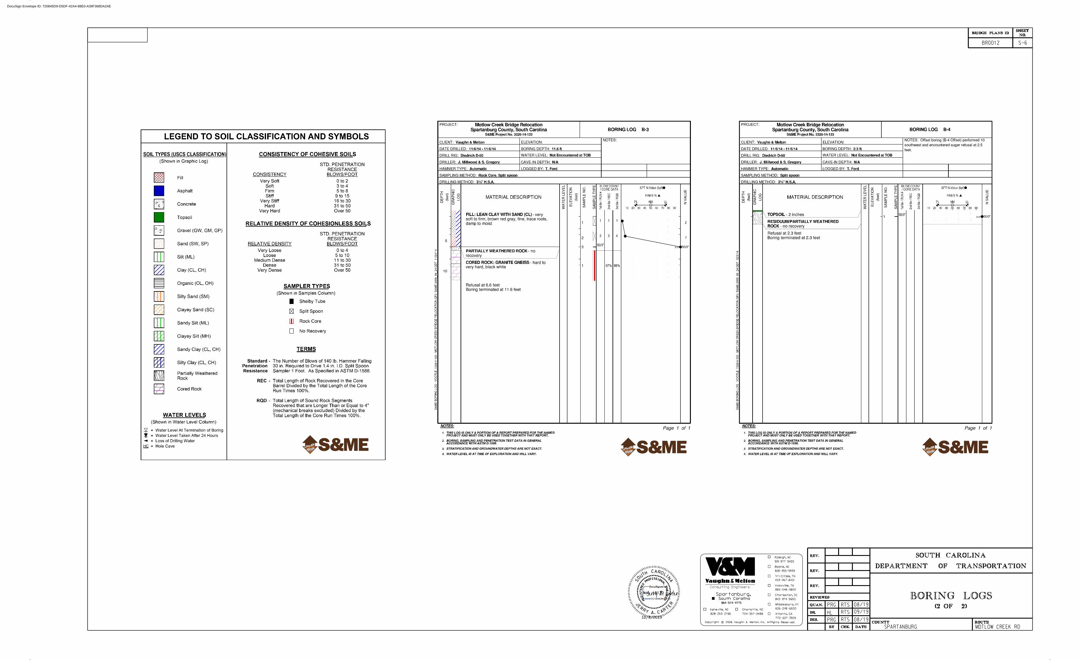
BORING LOGS
SPARTANBURG
423 467 8401
865 546 5800
606 248 6600
Tri-Cities, TN
Knoxville, TN
Middlesboro, KY
Charleston, SC
843 974 5650
Atlanta, GA
770 627 3509
cCopyright 2006 Vaughn & Melton, Inc. All Rights Reserved
Consulting Engineers
Boone, NC
828 355 9933
704 357 0488
Charlotte, NC
919 977 9455
Raleigh, NC
828 253 2796
Asheville, NC
Spartanburg,South Carolina
864 574 4775
A
I
N
HT
O
UL
ROCA
S
.
E
A
T
J
RRY CAR
ER
No. 19170
RE
EN
IG
NE
LA
NOISSEFOR
P
DE
RE
TS
IG
ER
PRG
HL
RTS 08/19
RTS
RTSPRG
09/19
08/19
(1 OF 2)
DocuSign Envelope ID: 720845D9-D5DF-42A4-88E0-A39F368DA2AE
10/8/2019
SOUTH CAROLINA
DEPARTMENT OF TRANSPORTATION
REV.
REV.
REV.
REVIEWED
QUAN.
DR.
DES.
BY CHK. DATE
NO.SHEET
COUNTY ROUTEMOTLOW CREEK RD
BRIDGE PLANS ID
BR0012 S-6
BORING LOGS
SPARTANBURG
423 467 8401
865 546 5800
606 248 6600
Tri-Cities, TN
Knoxville, TN
Middlesboro, KY
Charleston, SC
843 974 5650
Atlanta, GA
770 627 3509
cCopyright 2006 Vaughn & Melton, Inc. All Rights Reserved
Consulting Engineers
Boone, NC
828 355 9933
704 357 0488
Charlotte, NC
919 977 9455
Raleigh, NC
828 253 2796
Asheville, NC
Spartanburg,South Carolina
864 574 4775
A
I
N
HT
O
UL
ROCA
S
.
E
A
T
J
RRY CAR
ER
No. 19170
RE
EN
IG
NE
LA
NOISSEFOR
P
DE
RE
TS
IG
ER
PRG RTS
HL
08/19
PRG
RTS
RTS
09/19
08/19
(2 OF 2)
DocuSign Envelope ID: 720845D9-D5DF-42A4-88E0-A39F368DA2AE
10/8/2019

SOUTH CAROLINAREV.
REV.
REV.
REVIEWED
QUAN.
DR.
DES.
BY CHK. DATE
NO.SHEET
COUNTY ROUTE
BRIDGE PLANS ID
SPARTANBURG COUNTY
BR0012
C -L-L
AHEAD STA.
FOUNDATION LAYOUT
L
38'-
6"
8'-6
"
60°00' 00"
60°00' 00"
60°00' 00"
BACKWALLFRONT FACE
BACKWALLFRONT FACE
8'-
6"
8'-6"
8'-
6"
8'-6"
8'-6
"
6Ž"
19'-
3‡
"
19'-
2„
"
6Ž"
38'-
6"
LC FTG.
19'-
2„
"
19'-
3‡
"
LC FTG.
6Ž"
60°00' 00"
60°00' 00"
9'-1‡"
9'-
1‡
"
6Ž"
9'-1‡"
60°00' 00"
5'-
1‡
"
FOOTING PLAN
LENGTH = 40'-3•"
BRG. = N8°0'58"W
C BRIDGE CHORD
SPARTANBURG MOTLOW CREEK RD
S-7
423 467 8401
865 546 5800
606 248 6600
Tri-Cities, TN
Knoxville, TN
Middlesboro, KY
Charleston, SC
843 974 5650
Atlanta, GA
770 627 3509
cCopyright 2006 Vaughn & Melton, Inc. All Rights Reserved
Consulting Engineers
Boone, NC
828 355 9933
704 357 0488
Charlotte, NC
919 977 9455
Raleigh, NC
828 253 2796
Asheville, NC
Spartanburg,South Carolina
864 574 4775
4'-3
"
4'-3
" 4'-3
"
2'-1•"
2'-1•"
FLOW
A
I
N
HT
O
UL
ROCA
S
.
E
A
T
J
RRY CAR
ER
No. 19170
RE
EN
IG
NE
LA
NOISSEFOR
P
DE
RE
TS
IG
ER
8'-0„"
8'-0„"
8'-
0„
"
4'-
0„
"
2'-1•"
4'-3
"
2'-1•"
6'-
11‚
"
16'-
0‚
"
15'-
11̂
"
6'-
11‚
"
4'-
3"
4'-
3"
7'-
11„
"
7'-
11„
"
4'-
3"
16'-
0‚
"
15'-
11̂
"
6'-
11‚
"
4'-
3"
3'-
5†
"
7'-
11„
"
4'-
5Œ
"
PRG RTS
HL
08/19
09/19
08/19
RTS
RTSPRG
ABUTMENT 1
ABUTMENT 2
ABUTMENT 1
FRONT FACE BACKWALL@
STA. 18+29.85
BEGIN BRIDGE
W.P. 1
ABUTMENT 2
FRONT FACE BACKWALL@
STA. 18+70.15
END BRIDGE
W.P. 2
-N-
DocuSign Envelope ID: 720845D9-D5DF-42A4-88E0-A39F368DA2AE
10/8/2019

SOUTH CAROLINAREV.
REV.
REV.
REVIEWED
QUAN.
DR.
DES.
BY CHK. DATE
NO.SHEET
COUNTY ROUTE
BRIDGE PLANS ID
11x17 plot
SPARTANBURG COUNTY
BR0012
ABUTMENT 1REINFORCING PLAN
FOOTING
SCALE …" = 1'-0"
L
C -L-L
W.P. 1
STA. 18+29.85
AH
EA
D S
TA.
60°00' 00"
C FTG.L
60°00' 00"60°00' 00"
(TYP.)
MIN. SPLICE
1'-9"
6"6"
9'-1‡"
9'-1
‡"
8'-0
„"
FOOTING REINFORCING PLAN - ABUTMENT 1
8'-
6"
3"
3"
(TOP
&
BO
TT
OM)
9 -
A1302
@ 12"
O.C.
3"
8'-0„"
3"
3"
3"
8'-
6"
(TOP
&
BO
TT
OM)
9 -
A1302
@ 12" O.C.
NOTES:
SPARTANBURG MOTLOW CREEK RD
S-8
C BRIDGE CHORD
423 467 8401
865 546 5800
606 248 6600
Tri-Cities, TN
Knoxville, TN
Middlesboro, KY
Charleston, SC
843 974 5650
Atlanta, GA
770 627 3509
cCopyright 2006 Vaughn & Melton, Inc. All Rights Reserved
Consulting Engineers
Boone, NC
828 355 9933
704 357 0488
Charlotte, NC
919 977 9455
Raleigh, NC
828 253 2796
Asheville, NC
Spartanburg,South Carolina
864 574 4775
2'-
1•
"
4'-
3"
4'-
3"
46 - J1901 @ 10" SP. (TOP)
92 - J2501 @ 5" SP. (BOTTOM) 3•"3•"
3"
3"
8'-
6"
2'-
1•
"
11- J2201 @ 10" O.C. (TOP)
11- J1301 @ 10" O.C. (BOTTOM)
11- J2201 @ 10" O.C. (TOP)
11- J1301 @ 10" O.C. (BOTTOM)
A
I
N
HT
O
UL
ROCA
S
.
E
A
T
J
RRY CAR
ER
No. 19170
RE
EN
IG
NE
LA
NOISSEFOR
P
DE
RE
TS
IG
ER
S-10 AND S-13 FOR BAR LOCATIONS.
1. STEMWALL RENFORCING BARS NOT SHOWN FOR CLARITY. SEE SHEETS
(2-
BA
R
RU
N)
(TO
P
&
BO
TT
OM)
9 -
A1301
@ 12"
CT
S.
PRG RTS
HL
08/19
PRG
RTS
RTS
09/19
08/19
5'-
1ƒ
"7'-
4Š
"
6'-11‚"6'-11‚" 15'-11ˆ"16'-0ƒ"
31'-11Ž"
6Ž
"
6Ž
"
7'-
4Š
"5'-
1•
"
4'-
0ˆ
"
4'-
0ˆ
"19'-2„"19'-3‡"
38'-6"
7'-11„" 7'-11„"
ABUTMENT 1
BEGIN BRIDGE
FRONT FACE BACKWALL@
OF BACKWALLFRONT FACE
DocuSign Envelope ID: 720845D9-D5DF-42A4-88E0-A39F368DA2AE
10/8/2019

SOUTH CAROLINA
NO.SHEET
ROUTE
BRIDGE PLANS ID
SPARTANBURG COUNTY
BR0012
ABUTMENT 2REINFORCING PLAN
FOOTING
SCALE …" = 1'-0"11x17 plot
REV.
REV.
REV.
REVIEWED
QUAN.
DR.
DES.
BY CHK. DATE
COUNTY
L C -L-L
AH
EA
D S
TA.
C FTG.L
60°00' 00"
60°00' 00"
(TYP.)
MIN. SPLICE
1'-9"
6"6"
9'-1
‡"
60°00' 00"
5'-1‡"
FOOTING REINFORCING PLAN - ABUTMENT 2
8'-0
„"
8'-
6"
3"
3"
3"
(TOP
&
BO
TT
OM)
9 -
A1302
@ 12" O.C.
(TOP
&
BO
TT
OM)
9 -
A1303
@ 12"
O.C.
4'-0„"
3"
3"
3"
8'-
6"
NOTES:
SPARTANBURG MOTLOW CREEK RD
S-9
C BRIDGE CHORD
423 467 8401
865 546 5800
606 248 6600
Tri-Cities, TN
Knoxville, TN
Middlesboro, KY
Charleston, SC
843 974 5650
Atlanta, GA
770 627 3509
cCopyright 2006 Vaughn & Melton, Inc. All Rights Reserved
Consulting Engineers
Boone, NC
828 355 9933
704 357 0488
Charlotte, NC
919 977 9455
Raleigh, NC
828 253 2796
Asheville, NC
Spartanburg,South Carolina
864 574 4775
2'-
1•
"
4'-
3"
4'-
3"
46 - J1901 @ 10" SP. (TOP)
92 - J2501 @ 5" SP. (BOTTOM)
3"
3"
8'-
6"
2'-
1•
"
6 - J1301 @ 10" O.C. (BOTTOM)
6 - J2201 @ 10" O.C. (TOP) 11 - J1301 @ 10" O.C. (BOTTOM)
11 - J2201 @ 10" O.C. (TOP)
A
I
N
HT
O
UL
ROCA
S
.
E
A
T
J
RRY CAR
ER
No. 19170
RE
EN
IG
NE
LA
NOISSEFOR
P
DE
RE
TS
IG
ER
S-11 AND S-14 FOR BAR LOCATIONS.
1. STEMWALL RENFORCING BARS NOT SHOWN FOR CLARITY. SEE SHEETS
(2-
BA
R
RU
N)
(TO
P
&
BO
TT
OM)
9 -
A1301
@ 12"
CT
S.
31'-11Ž"
16'-0ƒ" 15'-11ˆ" 6'-11‚"3'-5†"
7'-
4Š
"5'-
1•
"
4'-
0ˆ
"
6Ž
"
7'-
4Š
"3'-
1•
"
2'-
0ˆ
"
19'-2„"19'-3‡"4'-5Œ"
38'-6"
7'-11„"
6Ž
"
ABUTMENT 2
FRONT FACE BACKWALL@
STA. 18+70.15
END BRIDGE
W.P. 2
OF BACKWALLFRONT FACE
PRG RTS
HL
08/19
PRG
RTS
RTS
09/19
08/19
3•" 3•"
DocuSign Envelope ID: 720845D9-D5DF-42A4-88E0-A39F368DA2AE
10/8/2019

PLAN
AH
EA
D S
TA
TIO
NS
38'-6"
19'-2„" 19'-3‡"
2'-
0"
2'-
0"
1'-
9ƒ
"
2'-
0"
1'-
9ƒ
"
BOTTOM FTG.
POINT A
POINT B
POINT C
1'-
1•
"9"
1•
"
FRONT FACE
FILL FACE
ELEVATIONSTOP OF END BENT
A
B
C
D
892.06
892.06
893.71
6" 6"
ELEVATION
NOTE:
L
JT. MAT'L
1•" EXP.
JT. MAT'L
1•" EXP.
FIELD BEND
1. SEE SHEET S-12 FOR SECTION A-A
2'-5‰"
4 - A1301
A1301 E.F.
SOUTH CAROLINAREV.
REV.
REV.
REVIEWED
QUAN.
DR.
DES.
BY CHK. DATE
NO.SHEET
COUNTY ROUTESPARTANBURG MOTLOW CREEK RD
BRIDGE PLANS ID
SPARTANBURG COUNTY
BR0012
W1 W2
J1302 J1302
LIMITS OF CONC. FTG.
J1302
J1302
A
A
1'-9" MIN. SPLICE (TYP.)
J2202
J2202
1'-10…"
1'-5ˆ"
2'-0"
S-10
423 467 8401
865 546 5800
606 248 6600
Tri-Cities, TN
Knoxville, TN
Middlesboro, KY
Charleston, SC
843 974 5650
Atlanta, GA
770 627 3509
cCopyright 2006 Vaughn & Melton, Inc. All Rights Reserved
Consulting Engineers
Boone, NC
828 355 9933
704 357 0488
Charlotte, NC
919 977 9455
Raleigh, NC
828 253 2796
Asheville, NC
Spartanburg,South Carolina
864 574 4775
A1304 E.F.
PO
UR #1
PO
UR #2
PO
UR #3
POINT D
L
-L- STA. 18+29.85FRONT FACE OF BACKWALL
BEGIN BRIDGEW.P. #1
1'-7Œ" 1'-10"
5‹"
1'-2„"
(TYP.) (TYP.)
-L-
1'-4‚" TO
POINT A
POINT B
2'-6ˆ" TO
POINT C
2'-6ˆ" TO
POINT D
1'-4‚" TO
L
2'-10"
1'-5" 1'-5"
3"
6"
3"
1'-
6"
CHORDBRIDGE
17'-9‡" 16'-9Ž"
(TYP.)9" ABOVE CAPTO PROJECT
A2501 DOWELS
L
BRG. PAD (TYP.)FIXED ELASTOMERIC
ƒ" X 6" X 2'-10"
C FIXED BEARING
C
BR
G.
1'-
6"
TO
C FIXED BEARING
FIXED BEARING DETAIL
3. WING WALLS NOT SHOWN IN ELEVATION VIEW FOR CLARITY.
3•"
3•"
3•"
3•"
ABUTMENT 1
34 - J1302 @ 12" O.C.
3•" 3•"
SLAB UNITC CORED
893.71
(LEVEL)EL. 893.71
(LEVEL)EL. 892.06
7'-
0‡
"
EL. 882.99
EL. 884.99TOP FTG.
3•" 3•"
(TOP & BOTTOM)A1301 @ 12" O.C.
A
I
N
HT
O
UL
ROCA
S
.
E
A
T
J
RRY CAR
ER
No. 19170
RE
EN
IG
NE
LA
NOISSEFOR
P
DE
RE
TS
IG
ER
FILL FACE
11"11"
1'-10"
(TYP.) SUPER STRUCTURE
EAGE OF
2. SEE SHEET S-13 FOR DETAILS.
UNIT (TYP.)C CORED SLABL
92 - J2202 @ 5" O.C. (LAP WITH A2201 VERTICAL BARS)
34 - J1302 @ 12" O.C.
4.76%
EL. 893.87
1'-
0"
12"
O.C. (2
BA
R
RU
N)
8'-
A1301 E.F.
@2•
"3"
10
‰"
92 - C2201 @ 5" O.C. FILL FACE & 92 - C2202 @ 5" O.C. FRONT FACE
92 - A2201 @ 5" O.C. EACH FACE ( LAP WITH C2201 + C2202)
46 - J1901 @ 10" O.C. (TOP)
92 - J2501 @ 5" O.C. (BOTTOM)
11"
O.C. (2
BA
R
RU
N)
8'-
A1301 E.F.
@3"
PRG RTS
HL
08/19
PRG
RTS
RTS
09/19
08/19
92 - J2202 @ 5" O.C. (LAP WITH A2201 VERTICAL BARS)
EL. 895.52
8'-
8†
"
DocuSign Envelope ID: 720845D9-D5DF-42A4-88E0-A39F368DA2AE
10/8/2019

ELEVATIONSTOP OF END BENT
A
B
C
D
891.79
891.79
893.58
893.58
1'-
9ƒ
"
1'-
9ƒ
"
2'-
0"
2'-
0"
38'-6"
19'-3‡"
POINT B
POINT C
POINT D
FRONT FACE
FILL FACE
2'-
0"
POINT A
1'-
1•
"9"
1•
"
19'-2„"
AH
EA
D S
TA
TIO
NS
6" 6"
PLAN
ELEVATION
L
FIELD BEND
4 - A1301
A1301 E.F.
NOTE:
JT. MAT'L
1•" EXP.
4.90%
SOUTH CAROLINAREV.
REV.
REV.
REVIEWED
QUAN.
DR.
DES.
BY CHK. DATE
NO.SHEET
COUNTY ROUTESPARTANBURG MOTLOW CREEK RD
BRIDGE PLANS ID
SPARTANBURG COUNTY
BR0012
W3 W4
B
B
LIMITS OF CONC. FTG.
J1302
J1302
J1302
1'-9" MIN. SPLICE (TYP.)
JT. MAT'L
1•" EXP.
J2202 J2202
2'-0"
2'-5‰"
1'-10…"
1'-5ˆ"
S-11
423 467 8401
865 546 5800
606 248 6600
Tri-Cities, TN
Knoxville, TN
Middlesboro, KY
Charleston, SC
843 974 5650
Atlanta, GA
770 627 3509
cCopyright 2006 Vaughn & Melton, Inc. All Rights Reserved
Consulting Engineers
Boone, NC
828 355 9933
704 357 0488
Charlotte, NC
919 977 9455
Raleigh, NC
828 253 2796
Asheville, NC
Spartanburg,South Carolina
864 574 4775
A1304 E.F.
(LEVEL)EL. 893.58
6'-
11‚
"
PO
UR #2
PO
UR #1
PO
UR #3
-L- STA. 18+70.15FRONT FACE OF BACKWALL
END BRIDGEW.P. #2
L
(TYP.)(TYP.)
-L-
6"
3"
3"
SLAB UNITC CORED
1'-
6"
1'-5" 1'-5"
2'-10"
L
L
POINT A
1'-4‚" TO
POINT B
2'-6ˆ" TO
POINT D
1'-4‚" TO
POINT C
2'-6ˆ" TO
CHORDBRIDGE
1'-7Œ"1'-10"
5‹"
1'-2„"
(TYP.)9" ABOVE CAPTO PROJECT
A2501 DOWELS
BRG. PAD (TYP.)EXPANSION ELASTOMERIC
ƒ" X 6" X 2'-10"
C EXPANSION BEARING
C
BR
G.
1'-
6"
TO
17'-9‡"
1. SEE SHEET S-12 FOR SECTION B-B.
3. WING WALLS NOT SHOWN IN ELEVATION VIEW FOR CLARITY.
BEARINGC EXPANSION
EXPANSION BEARING DETAIL
ABUTMENT 2
3•"
3•" 3•"
34 - J1302 @ 12" SP.
(LEVEL)EL. 891.79
EL. 886.64TOP FTG.
EL. 884.64BOTTOM FTG.
5'-
1Ž
"
3•" 3•"
(TOP & BOTTOM)A1301 @ 12" O.C.
4'-10•"
A
I
N
HT
O
UL
ROCA
S
.
E
A
T
J
RRY CAR
ER
No. 19170
RE
EN
IG
NE
LA
NOISSEFOR
P
DE
RE
TS
IG
ER
J1302
2•
"
FILL FACE1'-10"
11" 11"
2•" AT TOP OF WALLAS NECESSARY TO PROVIDEFIELD CUT C2201 & C2202
(TYP.) SUPER STRUCTURE@
EDGE OF
34 - J1302 @ 12" O.C.
92 - J2202 @ 5" O.C. (LAP WITH A2202, OR C2201, OR C2202 VERTICAL BARS)
WITH (TYP.)C CORED SLABL
2. SEE SHEET S-14 FOR DETAILS.
EL. 895.39
EL. 893.60
92 - J2202 @ 5" O.C. (LAP WITH A2202, OR C2201, OR C2202 VERTICAL BARS)
12"
O.C. (2-
BA
R
RU
N)
3 -
A1301 E.F.
@
3"
12"
O.C. (2-
BA
R
RU
N)
6 -
A1301 E.F.
@
9"
3"
2•
"6•
"
92 - C2201@ 5" O.C. FILL FACE & 92 - C2202@ 5" O.C. FRONT FACE
81- A2202 E.F. @ 5" O.C. (LAP WITH C2201 & 2202)
46 - J1901 @ 10" O.C. (TOP)
92 - J2501 @ 5" O.C. (BOTTOM)
PRG RTS
HL
08/19
09/19
08/19
RTS
RTSPRG
DocuSign Envelope ID: 720845D9-D5DF-42A4-88E0-A39F368DA2AE
10/8/2019

VA
RIE
S
2'-0"
1'-0"
1•" 9" 1'-1•"
2'-
0"
1'-
9ƒ
"
2'-
0"
3"
CL.
2"
CL.
1'-
9ƒ
"2'-
0"
VA
RIE
S
2'-0"
1'-0"
1•"9"1'-1•"
2'-
0"
2"
CL.
SECTION B-B (ABUTMENT 2)SECTION A-A (ABUTMENT 1)
7'-
0‡
" T
O 8'-
8†
"
(E.F., 2-
BA
R
RU
N)
4 - A1301
4 - A1301
(E.F., 2-
BA
R
RU
N)
FILL
FLOWABLE
FILL
FLOWABLE
SOUTH CAROLINAREV.
REV.
REV.
REVIEWED
QUAN.
DR.
DES.
BY CHK. DATE
S-12
NO.SHEET
COUNTY ROUTESPARTANBURG MOTLOW CREEK RD
BRIDGE PLANS ID
SPARTANBURG COUNTY
BR0012
423 467 8401
865 546 5800
606 248 6600
Tri-Cities, TN
Knoxville, TN
Middlesboro, KY
Charleston, SC
843 974 5650
Atlanta, GA
770 627 3509
cCopyright 2006 Vaughn & Melton, Inc. All Rights Reserved
Consulting Engineers
Boone, NC
828 355 9933
704 357 0488
Charlotte, NC
919 977 9455
Raleigh, NC
828 253 2796
Asheville, NC
Spartanburg,South Carolina
864 574 4775
JT.
CONST.
JT.
CONST.
JT.
CONST.
A2501 DOWELLS
A2501 DOWELLS
JT.
CONST.
ABUTMENT SECTIONS
SHOWN FOR CLARITY)
(NOTE: SURFACE COURSE NOT
SECTION, SEE ROAD PLANS
FULL DEPTH PAVEMENT
SHOWN FOR CLARITY)
(NOTE: SURFACE COURSE NOT
SECTION, SEE ROAD PLANS
FULL DEPTH PAVEMENT
8'-6"
5'-6"
(1'-9" DEPTH)
CONC. CORED SLAB
(1'-9" DEPTH)
CONC. CORED SLAB
J2202
J2202
A
I
N
HT
O
UL
ROCA
S
.
E
A
T
J
RRY CAR
ER
No. 19170
RE
EN
IG
NE
LA
NOISSEFOR
P
DE
RE
TS
IG
ER
J2501
A1301
J1901
(TYP.)
2•" CL.
A2201
J1302
2•
" C
L.
@ 9"O.C.
A1304
J1901
5'-
1‡
" T
O 6'-
11‚
"
A2202
J1302
2•
" C
L.
@ 9"
O.C.
A1304
A1301
@ 12"
O.C.
MA
X
A1301
@ 12"
O.C.
MA
X
C2201
C2202
3"
CL.
8'-6"
5'-6"
J2501
A1301
(TYP.)
2•" CL.
C2201
C2202
(TYP.)
2•" CL.
(TYP.)
2•" CL.
PRG RTS
HL
08/19
PRG
RTS
RTS
09/19
08/19
(PO
UR #1)
(PO
UR #2)
(PO
UR #3)
(PO
UR #3)
(PO
UR #2)
(PO
UR #1)
2'-0"
1'-0"6" 6"FOOTING
TOP OF
1" (TYP.)
DETAIL THIS SHEET
SEE SHEAR KEY
DETAIL THIS SHEET
SEE SHEAR KEY
(ABUTMENT STEM ONLY)
SHEAR EKY DETAIL
DocuSign Envelope ID: 720845D9-D5DF-42A4-88E0-A39F368DA2AE
10/8/2019

PLAN OF WING W1PLAN OF WING W2
ELEVATION OF WING W1
ELEVATION OF WING W2
2'-
0"
2'-
0"
3"
8'-3‰"
3"
1'-
0"
1'-
0"
3"
3"
JT. MAT'L
1•" EXP.
2'-1•"
9"
1'-
1•
"
1•
"
JT. MAT'L
1•" EXP.
1'-1
1ƒ"
1'-
1•
"9"
1•
"
A
A
JT. MAT'L
1•" EXP.
JT. MAT'L
1•" EXP.
NO.SHEET
BRIDGE PLANS ID
BR0012
SOUTH CAROLINAREV.
REV.
REV.
REVIEWED
QUAN.
DR.
DES.
BY CHK. DATE
COUNTY ROUTE
SPARTANBURG COUNTY
423 467 8401
865 546 5800
606 248 6600
Tri-Cities, TN
Knoxville, TN
Middlesboro, KY
Charleston, SC
843 974 5650
Atlanta, GA
770 627 3509
Consulting Engineers
Boone, NC
828 355 9933
704 357 0488
Charlotte, NC
919 977 9455
Raleigh, NC
828 253 2796
Asheville, NC
Spartanburg,South Carolina
864 574 4775
MOTLOW CREEK RDSPARTANBURG
" = 1'-0"21
8'-0"
A
A
8'-3‰"
FILL FACE
8'-0"
CONST. JT.
CONST. JT.
2'-
0"
PO
UR #1
11'-
6"
PO
UR #2
PO
UR #3
CONST. JT.
CONST. JT.
PO
UR #1
2'-
0"
PO
UR #2
4'-
0"
PO
UR #3
A1305 THRU A1313 @ 1'-0" O.C.
STREAM FACE STREAM FACE
EL. 884.99
TOP OF FOOTING
EL. 894.49
TOP OF WINGWALL
EL. 892.06
EL. 892.49
C1601
C1603
C1606
3"
EL. 896.13
TOP OF WINGWALL
EL. 893.71
EL. 892.13
1'-
0"
3"
(ST
RE
AM
FA
CE)
8 - F1301
@ 1'-
0"
O.C.
(FIL
L
FA
CE)
8 - F1302
@ 1'-
0"
O.C.
(ST
RE
AM
FA
CE)
7 - F1305
@ 1'-
0"
O.C.
(FIL
L
FA
CE)
7 - F1306
@ 1'-
0"
O.C.
C1633
F1308 (FILL FACE)
F1307 (STREAM FACE)
F1314 (FILL FACE)
F1313 (STREAM FACE)
A1315 (FILL FACE)
A1314 (STREAM FACE)
NOTE:
1. SEE SHEET S-15 FOR SECTION A-A
FOOTING
LIMITS OF
FOOTING
LIMITS OF
1'-0"1'-0" FILL FACE
WING DETAILSABUTMENT 1
2'-
0"
7'-
6"
EL. 884.99
TOP OF FOOTING
7'-
1†
" 13'-
1†
"
A
I
N
HT
O
UL
ROCA
S
.
E
A
T
J
RRY CAR
ER
No. 19170
RE
EN
IG
NE
LA
NOISSEFOR
P
DE
RE
TS
IG
ER
S-13
2•
" C
L.
2•
" C
L.
A1316
A1317
C1601 THRU C1616 @ 6" O.C.
STREAM FACE
10" O.C.
2-A1313 @
A1315
A1314
C1617 THRU C1632 @ 6" O.C.
2•
" C
L.
2•
" C
L.
A1329
A1330
A1327
A1328
A1317 (FILL FACE)
A1316 (STREAM FACE)
F1304 (FILL FACE)
F1303 (STREAM FACE)
C1602
C1604
C1605
C1607
C1613
C1610
C1612
C1611
C1609
C1615
C1614
C1608
C1616
(ST
RE
AM
FA
CE)
F1309,
F1311
&
F1313 1'-
0"
O.C.
(FIL
L
FA
CE)
F1310,
F1312
&
F1314 1'-
0"
O.C.
A1328 (FILL FACE)
A1327 (STREAM FACE)
F1310 (FILL FACE)
F1309 (STREAM FACE)F1312 (FILL FACE)
F1311 (STREAM FACE)
A1330 (FILL FACE)
A1329 (STREAM FACE)
C1619
C1622
C1620
C1621
C1618
C1617
C1623
C1630
C1627
C1631
C1629
C1628
C1626
C1632
C1625
C1624
1'-
0"
PRG RTS
HL
08/19
PRG
RTS
RTS
09/19
08/19
8'-0"
8'-0"
EL. 882.99
BOTT OF FOOTING
1'-
0"
6'-
6"
1'-
0"
5'-
6"
FILL FACE
2-C1616 @ 10" O.C.
2" C
L.
STREAM FACE
10" O.C.
2 - A1326 @
A1318 THRU A1326 @ 1'-0" O.C.
1-0"
5'-
6"
1'-
0"
6'-
6"
FILL FACE
3-C1633 @ 10" O.C.
2" C
L.
EL. 882.99
BOTT OF FOOTING
DocuSign Envelope ID: 720845D9-D5DF-42A4-88E0-A39F368DA2AE
10/8/2019

3"
2'-
0"
1'-
0"
JT. MAT'L
1•" EXP.
JT. MAT'L
1•" EXP.
JT. MAT'L
1•" EXP.
JT. MAT'L
1•" EXP.
8'-3‰"
3"
1'-
0"
3"
8'-0"
PLAN OF WING W4
2'-1•"
2'-
0"
1'-
1•
"
9"
1•
"
4'-3‰"1'-1
1ƒ"
1'-
1•
"9"
1•
"
3"
4'-0"
FILL FACE
NO.SHEET
BRIDGE PLANS ID
BR0012
SOUTH CAROLINAREV.
REV.
REV.
REVIEWED
QUAN.
DR.
DES.
BY CHK. DATE
COUNTY ROUTE
SPARTANBURG COUNTY
423 467 8401
865 546 5800
606 248 6600
Tri-Cities, TN
Knoxville, TN
Middlesboro, KY
Charleston, SC
843 974 5650
Atlanta, GA
770 627 3509
cCopyright 2006 Vaughn & Melton, Inc. All Rights Reserved
Consulting Engineers
Boone, NC
828 355 9933
704 357 0488
Charlotte, NC
919 977 9455
Raleigh, NC
828 253 2796
Asheville, NC
Spartanburg,South Carolina
864 574 4775
SPARTANBURG MOTLOW CREEK RD
" = 1'-0"21
CONST. JT.
CONST. JT.
2'-
0"
B
EL. 894.22
TOP OF WINGWALL
1'-
0"
5'-
7"
9'-
7"
B
EL. 886.64
TOP OF FOOTING
PO
UR #1
PO
UR #2
PO
UR #3
B
B
EL. 886.64
TOP OF FOOTING
ELEVATION OF WING W4
CONST. JT.
2'-
0"
PO
UR #3
PO
UR #2
PO
UR #1
EL. 896.00
TOP OF WINGWALL
STREAM FACE
STREAM FACE
@ 1'-0" O.C.
A1331 THRU A1334
A1340 THRU A1348 @ 1'-0" O.C.
1'-
0"
EL. 891.79
EL. 893.58
3"
(ST
RE
AM
FA
CE)
6 - F1315
@ 1'-
0"
O.C.
EL. 892.22
F1318 (FILL FACE)
F1317 (STREAM FACE)
A1337 (FILL FACE)
A1336 (STREAM FACE)
C1642
C1659
A1350 (FILL FACE)
A1349 (STREAM FACE)
F1322 (FILL FACE)
F1321 (STREAM FACE)
3"
EL. 894.50
ELEVATION OF WING W3
NOTE:
1. SEE SHEET S-15 FOR SECTION B-B
FOOTING
LIMITS OF
FOOTING
LIMITS OF
PLAN OF WING W3
1'-0"
1'-0"
FILL FACE
WING DETAILSABUTMENT 2
1'-
6"
A
I
N
HT
O
UL
ROCA
S
.
E
A
T
J
RRY CAR
ER
No. 19170
RE
EN
IG
NE
LA
NOISSEFOR
P
DE
RE
TS
IG
ER
S-14
7'-
10
…"
2•
" C
L.
2•
" C
L.
C1634 THRU C1641 @ 6" O.C.
A1338
A1339
2•
" C
L.
2•
" C
L.
C1643 THRU C1658 @ 6" O.C.
A1339 (FILL FACE)
A1338 (STREAM FACE)
C1641
C1640
C1639
C1638
C1635
C1636
C1637
C1634
A1352 (FILL FACE)
A1351 (STREAM FACE)
11'-
4…
"
CONST. JT.
C1657
C1656
C1655
C1658
C1644
C1645
C1646
C1643
C1654
C1653
C1652
C1648
C1649
C1647
C1650
C1651
(FIL
L
FA
CE)
8 - F1320
@ 1'-
0"
O.C.
(ST
RE
AM
FA
CE)
8 - F1319
@ 1'-
0"
O.C.
(FIL
L
FA
CE)
6 - F1316
@ 1'-
0"
O.C.
2'-
0"
PRG RTS
HL
08/19
09/19
08/19
RTS
RTSPRG
1'-
0"
6'-
6"
5'-
6"
1'-
0"
STREAM FACE
@ 9" O.C.
3 - A1335
FILL FACE
@ 9" O.C.
3 - C1642
CL.2"
A1336
A1337
1'-
0"
6'-
6"
1'-
0"
5'-
6"
A1351
A1352
STREAM FACE
@ 10" O.C.
2 - A1348
FILL FACE
@ 10" O.C.
2 - C1659
A1350
A1349
2" CL.
DocuSign Envelope ID: 720845D9-D5DF-42A4-88E0-A39F368DA2AE
10/8/2019

SECTION A-A (WINGWALLS 1 & 2) SECTION B-B (WINGWALLS 3 & 4)
2'-
0"
2'-
0"
8'-6"
1'-0"6'-6" 1'-0"
FILL FACE
FILL FACE
STREAM FACE
2'-
0" (W
W
1)
4'-
0" (W
W
2)
1'-
6" (W
W
4)
CONST. JT.
CONST. JT.
CL.
CL.
CL.
CL.
3"
CL.
3"
CL.
4"
CL.
4"
CL.
WINGWALL SECTIONS
SOUTH CAROLINAREV.
REV.
REV.
REVIEWED
QUAN.
DR.
DES.
BY CHK. DATE
S-15
NO.SHEET
COUNTY ROUTESPARTANBURG MOTLOW CREEK RD
BRIDGE PLANS ID
SPARTANBURG COUNTY
BR0012
423 467 8401
865 546 5800
606 248 6600
Tri-Cities, TN
Knoxville, TN
Middlesboro, KY
Charleston, SC
843 974 5650
Atlanta, GA
770 627 3509
cCopyright 2006 Vaughn & Melton, Inc. All Rights Reserved
Consulting Engineers
Boone, NC
828 355 9933
704 357 0488
Charlotte, NC
919 977 9455
Raleigh, NC
828 253 2796
Asheville, NC
Spartanburg,South Carolina
864 574 4775
7'-
6" (W
W
1)
2'-
0" (W
W
3)
5'-
7" (W
W
3)
STREAM FACE
PO
UR #2
PO
UR #1
PO
UR #3
CONST. JT.
CL.
2"
CL.
2"
CONST. JT. PO
UR #3
PO
UR #2
PO
UR #1
3"
3"
1'-0"
1'-0"
( ABUTMENT 1 ) ( ABUTMENT 2 )
7'-
10
…" (W
W
4)
7'-
1†
" (W
W
2)
A
I
N
HT
O
UL
ROCA
S
.
E
A
T
J
RRY CAR
ER
No. 19170
RE
EN
IG
NE
LA
NOISSEFOR
P
DE
RE
TS
IG
ER
J1301
J2201
A1302
8'-6"
6'-6"
J1301
J2201
2•"
2•"
A1327 THRU A1330 (WW2)
A1314 THRU A1317 (WW1)
C1617 THRU C1633 (WW2)
C1601 THRU C1616 (WW1) A1318 THRU A1326 (WW2)
A1305 THRU A1313 (WW1)
A1302 (WW4)A1303 (WW3)
2•"
2•"
A1349 THRU A1352 (WW4)
A1336 THRU A1339 (WW3)
(WW4)A1340 THRU A1348
(WW3)A1331 THRU A1335
#13 "F
" @ 1'-
0"
CT
S. (E
A.
FA
CE)
#13 "F
" @ 1'-
0"
CT
S. (E
A.
FA
CE)
C1643 THRU C1658 (WW4)
C1634 THRU C1642 (WW3)
PRG RTS
HL
08/19
09/19
08/19
RTS
RTSPRG
1"
3"
3"
1'-0"
FOOTING
TOP OF
DETAIL THIS SHEET
SEE SHEAR KEY
DETAIL THIS SHEET
SEE SHEAR KEY
SHEAR KEY DETAIL( WINGWALLS ONLY )
DocuSign Envelope ID: 720845D9-D5DF-42A4-88E0-A39F368DA2AE
10/8/2019

SOUTH CAROLINA
DEPARTMENT OF TRANSPORTATION
REV.
REV.
REV.
REVIEWED
QUAN.
DR.
DES.
BY CHK. DATE
NO.SHEET
COUNTY ROUTEMOTLOW CREEK RD
BRIDGE PLANS ID
BR0012 S-16
SPARTANBURG
MARK REQ'DNO.
LENGTHDIMENSIONS
"a" "b" "c" "d"
A1301 20'-0" 20'-0"
Notes:
A1305
A1307
A1308
A1309
7'-6"
8'-0"
8'-3"
1
1
1
A1302 36 9'-6" 9'-6"
80
A1311 1
A1314 1 1'-9"
423 467 8401
865 546 5800
606 248 6600
Tri-Cities, TN
Knoxville, TN
Middlesboro, KY
Charleston, SC
843 974 5650
Atlanta, GA
770 627 3509
cCopyright 2006 Vaughn & Melton, Inc. All Rights Reserved
Consulting Engineers
Boone, NC
828 355 9933
704 357 0488
Charlotte, NC
919 977 9455
Raleigh, NC
828 253 2796
Asheville, NC
Spartanburg,South Carolina
864 574 4775
A1306
A1310
A1315
A1316
A1317
A1318
A1319
A1320
A1321
A1322
A1323
A1324
A1325
A1312
A1313
1
3
1
1
1
1
1
1
1
1
1
1
1
1
3
MARK REQ'DNO.
LENGTHDIMENSIONS
"a" "b" "c" "d"MARK REQ'D
NO.LENGTH
DIMENSIONS
"a" "b" "c" "d"
A1301 20'-0" 20'-0"
A1332
A1334
A1335
A1336
1
3
1
A1302
A1303
18
18
9'-6" 9'-6"
72
1
1
11'-3"
J1301 17
3'-2"
1'-7"
1'-5"
5'-7"2'-0"J2202 92
A1333
A1337
A1338
A1339
A1340
A1341
1
1
1
1
1
1
1
1
1
1
MARK REQ'DNO.
LENGTHDIMENSIONS
"a" "b" "c" "d"
F1320
F1322
F1323
8
F1317
F1319
F1321
8
F1316
SUBSTRUCTURE REINFORCEMENT SCHEDULEABUTMENT 2
1
5'-6"
1 7'-3•"
7'-9"
8'-6"
8'-9"
9'-0"
1'-2"
8'-0"
6'-11"
7'-5"
9'-4"
A1331 1
5'-10"
6'-9"
1'-10"
2'-0"
4'-5"
4'-3"
7'-10"
8'-0"
8'-2"
8'-9"
8'-11"
1
1
6
6 4'-0"
3'-10"
2'-6"
3'-10"
8'-0"
7'-10"
5'-10"
5'-10"
4'-4"
4'-2"
7'-2"
10'-2" 1'-0"
A1329
A1330
A2201
A2501
8'-10"
20
8'-10"
6'-10"
2'-6"
9'-0"
9'-1"
9'-4"
9'-10"
10'-1"
C1635
C1636
C1637
C1638
C1639
C1640
C1641 8'-7" 1'-0" 9'-7"
20
8'-1"
4'-11"
2'-6"
7'-2"
7'-5"
7'-8"
8'-4"
8'-2"
8'-5"
8'-8"
1 1'-9"
8'-10"
7'-6"
5'-6"
1'-10"
2'-0"
1'-9"
1'-10"
1'-9"
2'-0"
1'-2"
1'-7ˆ"
1'-8Ž" 1'-0"
1'-0„"
1'-6‰"
1'-7ˆ"
1'-6‰"
1'-8Ž"
11"
10•"
1'-0"
11"
10•"
SUBSTRUCTURE REINFORCEMENT SCHEDULEABUTMENT 1
6'-8"J1302 34
A
I
N
HT
O
UL
ROCA
S
.
E
A
T
J
RRY CAR
ER
No. 19170
RE
EN
IG
NE
LA
NOISSEFOR
P
DE
RE
TS
IG
ER
9'-10"
A1326 10'-11"10'-11"
7'-9"
8'-0"
8'-3"
8'-6"
8'-9"
9'-0"
8'-0"
6'-11"
7'-5"
8'-10"
9'-4"
9'-10"
A1304 12 18'-0" 18'-0"
1
8'-6"
C1601
C1602
C1603
C1604
C1605
C1606
C1607
C1608
C1609
C1610
C1611
C1612
C1613
C1614
C1615
C1616
1'-0"
10'-5"
A1327
A1328
1'-10"
2'-0"
184
1
1
1
1
2'-6"
6'-10"
8'-10"
8'-10"
2'-0"
1'-10"
1'-0"
1'-0"
1'-0"
1'-0"
1'-0"
1'-0"
1'-0"
1'-0"
1'-0"
1'-0"
1'-0"
1'-0"
1'-0"
1'-0"
1'-0"
8'-10•" 9'-10•"
10'-2•"9'-2•"
10'-0"
10'-1"
9'-5•" 10'-5•"
10'-4"
9'-7"
10'-8•"
10'-7"
9'-8•"
9'-11•" 10'-11•"
10'-10"
10'-3•" 11'-3•"
11'-1"
11'-2"
11'-5"
11'-6•"
11'-10•"
10'-6•"
10'-10•"
9'-6"C1617
22 1'-5"
1'-7"
J2201 22
J1302 34
46
2'-0"92J2202
92J2501
8'-1"
8'-1"
8'-1"
1'-7"
8'-1"
4" 3'-2"
1'-7"
1'-5"
6'-8"
11'-3"
10'-11"
5'-7"
11'-3"
10'-11"
J1901
J1301
11'-5" 1'-0"
9'-0"
9'-3"
9'-9"
10'-8"
11'-2"
6'-9"
C1618
C1619
C1620
C1621
C1622
C1623
C1624
C1625
C1626
C1627
C1628
C1629
C1630
C1631
C1632
C1633
1'-0"
1'-0"
1'-0"
1'-0"
1'-0"
1'-0"
1'-0"
1'-0"
1'-0"
1'-0"
1'-0"
1'-0"
1'-0"
1'-0"
1'-0"
1'-6"
9'-6"
10'-0"
10'-3"
10'-11•"
10'-9"
10'-2" 11'-2"
10'-5"
10'-11" 11'-11"
12'-2"
12'-5"
13'-1•"12'-1•"
8'-3"C2201
8'-9" 9'-9"
10'-6"
9'-11•"
11'-5"
11'-8"
11'-8" 12'-8"
11'-10•" 12'-10•"
12'-6" 13'-6"
7'-9"1'-0"6'-9"C2202
F1314
F1312
F1313
F1301
F1302
F1303
F1304
F1305
F1306
F1307
F1308
F1309
F1310
F1311
1
1
1
1
1
1
7
7
1
1
8
8
4'-1"
4'-1"
8'-0"
7'-10"
7'-8"
5'-9"
5'-7"
1'-7"
5'-10"
5'-8"
9'-10"
8'-0"
7'-10"
3'-8"
1'-6‰"
1'-0„"
1'-9"
1'-2"
1'-10"
2'-0"
1'-10"
2'-0"
1'-10"
2'-0"
1'-10"
2'-0"
1'-10"
1'-7ˆ"
1'-2"
1'-9"
1'-6‰"
1'-0„"
1'-7ˆ"
1'-8Ž"
1'-7ˆ"
1'-8Ž"
1'-8Ž"
1'-7ˆ"
10•"
7"
10•"
11"
9'-9"
9'-0"
7"
1'-0"
1'-0"
1'-0"
1'-0"
1'-0"
1'-7ˆ"
1'-8Ž"
9'-8"
9'-8"
7'-9"
7'-9"
1'-8Ž"2'-0"
3'-6"
1'-5"
1
1
5'-8"
5'-8"
3'-7"
3'-7"
7'-3•"
9'-3•" 9'-3•"
8'-2"8'-2"
1'-9"
1'-2"
7'-10•" 7'-10•"
8'-4•" 8'-4•"
10'-3•" 10'-3•"
A1304 36 18'-0" 18'-0"
A1342
A1343
A1344
A1345
A1346
A1347
C1646
C1647
C1648
C1649
C1650
C1651
C1652
C1653
C1654
C1645
C1644
C1643
C1642
9'-4"
9'-6"
9'-7"
9'-8"
10-4"
10'-5"
10'-6"
10'-7"
10'-8"
10'-9"
A2202
A2501
A1348
A1349
A1350
A1351
A1352
3
160
1
1
1
5'-4•"
6'-3•"
7'-4•"
7'-7•"
8'-4•"
8'-6•"
9'-1•"
1'-2"
7'-11"
2'-6"
4'-11"
7'-11"
8'-1"
1'-2"
1'-9"
9'-1•"
8'-11"
8'-9"
8'-6•"
8'-4•"
8'-2"
8'-0"
7'-10"
7'-7•"
4'-3"
4'-5"
2'-0"
1'-10"
7'-4•"
6'-9"
6'-3•"
5'-10"
5'-4•"
C1634 1
1
1
1
1
1
1
1
1'-0"
1'-0"
1'-0"
1'-0"
1'-0"
1'-0"
1'-0"
8'-1•"
6'-11•"
7'-10•"
7'-11•"
9'-1•"
8'-10•"
9'-4"
C1656
C1657
C1658
C1659
C2202 6'-9" 1'-0" 7'-9"
92 6'-9"
11'-9"
C1655
C2201
92
3
3
1
1
1
1
1
1
1
1
1
1
1
1
1
1
1
2
1'-0"
1'-0"
1'-0"
1'-0"
1'-0"
1'-0"
1'-0"
1'-0"
1'-0"
1'-0"
1'-0"
1'-0"
1'-0"
1'-0"
1'-0"
1'-0"
1'-0"
1'-0"
1'-6"
9'-2•"
9'-11•"
9'-9"
9'-5"
10'-2•"
10'-10•"
10'-11•"
10'-0•"
10'-1•"
10'-2•"
9'-10•"
9'-11•"
10'-3•"
11'-1•"
11'-0•"
11'-2•"
11'-3•"
10'-5"
10'-6"
10'-7"
10'-9"
11'-5"
11'-6"
11-7"
8'-3"
F1318
1
1
5'-5"
5'-3" 1'-2" 1'-0„"
7"
7"
9'-9"
9'-0"
6'-5"
J1901
J2201
46
17
8'-1"
4"
8'-1"
8'-1"
1'-7"
1'-5"
10'-11"
10'-11"
92J2501 8'-1" 1'-7" 11'-3"
1. For Bar Bending Details, see sheet titled "Reinforcing Bending Details".
SUBSTRUCTURE QUANTITIES
ABUTMENT 2ABUTMENT 1UNITITEM
Concrete for Structures - Class 4000
Reinf. Steel for Structures (Bridge)
C.Y.
LB.
62.0 52.5
12,14713,362
POUR #1
POUR #2
POUR #3
FOOTING
ABUTMENT STEM, LOWER PART OF WINGWALL
BACKWALL, UPPER PART OF WINGWALL
33.1 C.Y.
27.3 C.Y.
63.1 C.Y.TOTAL
2.7 C.Y.
CONCRETE QUANTIESABUTMENT 1
CONCRETE QUANTIESABUTMENT 2
POUR #1
POUR #2
POUR #3
FOOTING
BACKWALL, UPPER PART OF WINGWALLS
30.6 C.Y.
20.2 C.Y.
53.6 C.Y.TOTAL
ABUTMENT STEM, LOWER PART OF WINGWALLS
2.8 C.Y.
BILL OF MATERIALSUBSTRUCTURE
9'-10"
8'-11•"
1
1
1
1
1
1
1
1
1
1
1
1
1
1
1
2
1
92
92
3
1
1
1
1
1
1
1
1
1
1
1
1
1
1
1
11"
11"
11"
11"
7'-10"
PRG RTS
HL
08/19
09/19
08/19
RTS
RTSPRG
DocuSign Envelope ID: 720845D9-D5DF-42A4-88E0-A39F368DA2AE
10/8/2019

PLAN OF UNIT
1"
10
PR
ES
TR
ES
SE
D
CO
NC
RE
TE
CO
RE
D
SL
AB
UNIT
S
= 30'-
0"
1"
3'-0"
3'-11"
6" 6"
3'-0"
3'-11"
SOUTH CAROLINAREV.
REV.
REV.
REVIEWED
QUAN.
DR.
DES.
BY CHK. DATE
NO.SHEET
COUNTY ROUTE
BRIDGE PLANS ID
SPARTANBURG COUNTY
BR0012
60 DEGREE SKEWCONC. CORED SLAB PLAN
40'-0" PRESTRESSED
GD1601
J1307
(2 BAR RUNS)
BARRIER RAIL
VERTICAL CONCRETE
8-A1601 IN
47-GD1601 (SPACED AS SHOWN IN DETAIL ``A'') (TYP. EA. EXT. UNIT)
(2 BAR RUNS)
BARRIER RAIL
VERTICAL CONCRETE
8-A1601 IN
(TYP.)
MAT'L. IN RAIL
C •'' EXP. JT.L
J1307
J1307 J1307
GD1601
GD1601
GD1601(2 BAR RUNS)
BARRIER RAIL
VERTICAL CONCRETE
8-A1601 IN
(2 BAR RUNS)
BARRIER RAIL
VERTICAL CONCRETE
8-A1601 IN
(TYP.)
MAT'L. IN RAIL
C •'' EXP. JT.L
27'-
6" (C
LE
AR
RO
AD
WA
Y)
1'-
2"
1'-
2"
C -L-L
LC BRIDGE C -L-L
LC BRIDGE
LC BRIDGE
C -L-L
SPARTANBURG
40'-0''
MOTLOW CREEK RD
S-17
423 467 8401
865 546 5800
606 248 6600
Tri-Cities, TN
Knoxville, TN
Middlesboro, KY
Charleston, SC
843 974 5650
Atlanta, GA
770 627 3509
cCopyright 2006 Vaughn & Melton, Inc. All Rights Reserved
Consulting Engineers
Boone, NC
828 355 9933
704 357 0488
Charlotte, NC
919 977 9455
Raleigh, NC
828 253 2796
Asheville, NC
Spartanburg,South Carolina
864 574 4775
(2 BAR RUNS)A1301 (TYP.)
SPLICE
1'-9"
SHOWN IN DETAIL "A"
J1304 - J1307 PAIRS SPACED AS
6" CTS. = 7'-6"
J1302 PAIRS - 15 SPA. @ J1302 PAIRS - 16 SPA. @ 1'-0" CTS. = 16'-0"
1'-0" 1'-0"
(TYP. EA. SLAB UNIT)
12'' DIA. VOIDS
J1302
SHOWN IN DETAIL "A"
J1304 - J1307 PAIRS SPACED AS
J1302
6" CTS. = 7'-6"
J1302 PAIRS - 15 SPA. @
A
I
N
HT
O
UL
ROCA
S.
E
A
T
J
RRY CAR
ER
No. 19170
RE
EN
IG
NE
LA
NOISSEFOR
P
DE
RE
TS
IG
ER
GUTTERLINE
(TYP.)
60°-00'-00''
3'-5"
(TYP.)
SPLICE
(TYP.)
RECESS DETAILS
SEE GROUTED
GUTTERLINE
-L- STA. 18+29.85
BEGIN BRIDGE
W.P. #1
ABUTMENT #1
BACKWALL @
FRONT FACE
-L- STA. 18+70.15
END BRIDGE
W.P. #2
ABUTMENT #2
BACKWALL @
FRONT FACE
11'-11''14'-0•'' 14'-0•''
1'-3"
4"
1'-3"
4"
IN 3" HOLE (TYP.)
C 1‚" DIA. TIE ROD
1'-3"
4"
1'-3"
4"
IN 3" HOLE (TYP.)
C 1‚" DIA. TIE ROD
14'-0•''11'-11''14'-0•''
(TYP.)
MAT'L. IN RAIL
C •'' EXP. JT.
(TYP.)
MAT'L. IN RAIL
C •'' EXP. JT.L
PRG RTS
HL
08/19
09/19
08/19
RTS
RTSPRG
DocuSign Envelope ID: 720845D9-D5DF-42A4-88E0-A39F368DA2AE
10/8/2019

(TYP.)CONST. JT.
BARRIER PARAPET
CORED SLAB UNIT
A1601
DETAIL ``A''
2•"
2'-7†"
6"
6"
8•''
1'-
7''
3'-
0"
8•''
@ APPROX. EQ. SPA.
1'-0"
1'-0
"
SOUTH CAROLINAREV.
REV.
REV.
REVIEWED
QUAN.
DR.
DES.
BY CHK. DATE
NO.SHEET
COUNTY ROUTE
BRIDGE PLANS ID
SPARTANBURG COUNTY
BR0012
UNIT SIMILAR EXCEPT OMIT GD1601 BARS.
NOTE: EXTERIOR UNIT SHOWN - INTERIOR
(SIMILAR EACH END OF UNIT)
J1304-J1307 BARS SPLAYED
GD1601 @ 1'-0" CTS.9-GD1601 @ 6" CTS.
J1302
GD1601
2-J1301
J1304 (IN PAIRS)
J1305 (IN PAIRS)
J1306 (IN PAIRS)
J1307 (IN PAIRS)
SPARTANBURG
6-J1302 PAIRS @ VARIOUS SPA.
(SEE ' PLAN OF UNIT' FOR LAYOUT)
MOTLOW CREEK RD
423 467 8401
865 546 5800
606 248 6600
Tri-Cities, TN
Knoxville, TN
Middlesboro, KY
Charleston, SC
843 974 5650
Atlanta, GA
770 627 3509
cCopyright 2006 Vaughn & Melton, Inc. All Rights Reserved
Consulting Engineers
Boone, NC
828 355 9933
704 357 0488
Charlotte, NC
919 977 9455
Raleigh, NC
828 253 2796
Asheville, NC
Spartanburg,South Carolina
864 574 4775
2-J1601
ƒ" CHAMFER
VOIDS
12" DIA.
2•" DOWEL HOLES
A
I
N
HT
O
UL
ROCA
S
.
E
A
T
J
RRY CAR
ER
No. 19170
RE
EN
IG
NE
LA
NOISSEFOR
P
DE
RE
TS
IG
ER
14'-0•"
2'-7" 8" 8" 2'-7"
6"4"
MIN. SPLICE 1'-6"
4‚"
2-J1302 @ 12" MAX.
4‚"
1•" Cl.
(TYP.)
2-A1301 (LAP W/ 2-A1301)
(TY
P.)
10•
"
3ƒ" 3ƒ"
2-J1302
2-J1302
11'-1•" 11'-1•"
11'-11"14'-0•"
12"12"
4"
VOID (TYP.)12" DIA.
(1 OF 4)CONC. CORED SLAB DETAILS
PRESTRESSED
S-18
2-J1302 @ 6" = 2'-0"
2-J1301 (TYP.)
TYPICAL ELEVATION - 40' CORED SLAB UNIT
ELEVATION - 40' SPAN
GB1601
J1303 AND J1601 BARS NOT SHOWN FOR CLARITY.
TO CLEAR TRANSVERSE TIE RODS.
SHIFT J1302 STIRRUPS AS NECESSARY
NOTES:
L L
DIA. DOWEL HOLES (TYP.)
C BEARING & C 2•"
2-J1302 @ 6" = 2'-0"
40'-0"
11'-3"
PRG RTS
HL
08/19
PRG
RTS
RTS
09/19
08/19
DocuSign Envelope ID: 720845D9-D5DF-42A4-88E0-A39F368DA2AE
10/8/2019
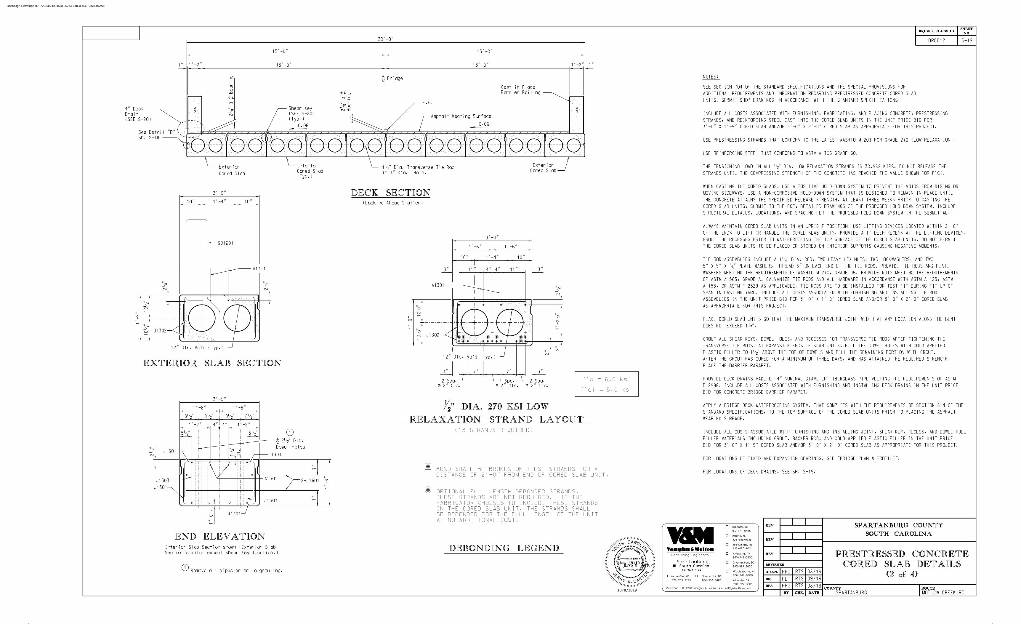
F.G.
DECK SECTION
Cored Slab
Exterior Cored Slab
Exterior
(Typ.)
Cored Slab
Interior
Asphalt Wearing Surface
GD1601
J1302
EXTERIOR SLAB SECTION
J1301
J1301
1
J1303
J1301
J1301
END ELEVATION
Dowel Holes
> 2•" Dia.
4" 4"
1
Section similar except Shear Key location.)
Interior Slab Section shown (Exterior Slab
Remove all pipes prior to grouting.
NOTES:
in 3" Dia. Hole.
1‚" Dia. Transverse Tie Rod
Barrier Railing
Cast-in-Place
J1303
2-J1601
12" Dia. Void (Typ,)
8•"
1'-2"
5•"
7"
7"
1"
Cl.
1‚
"
Cl.
2•
"
NO.SHEET
BRIDGE PLANS ID
BR0012
SOUTH CAROLINAREV.
REV.
REV.
REVIEWED
QUAN.
DR.
DES.
BY CHK. DATE
COUNTY ROUTE
SPARTANBURG COUNTY
15'-0"
13'-9"
SPARTANBURG
1'-9"
1'-2"1"
0.06
1'-4" 10"10"
3'-0"
2‡
"
10•
"
1'-9"
10•
"
2•
"
J1302
12" Dia. Void (Typ,)
1'-4" 10"10"
3'-0"
10•
"
1'-9"
10•
"
2•
"1'-2•
"2"
2"
7" 7"3" 3"
@ 2" Cts.
2 Spa.
@ 2" Cts.
2 Spa.
@ 2" Cts.
4 Spa.
3" 3"4" 11"4"11"
1'-6" 1'-6"
(13 STRANDS REQUIRED)
DEBONDING LEGEND
5•"
1'-2"
9•" 9•" 8•"
1'-6"1'-6"
3'-0"
0.06
A1301
A1301
A1301
RELAXATION STRAND LAYOUT" DIA. 270 KSI LOW2
1
DISTANCE OF 2'-0" FROM END OF CORED SLAB UNIT.
BOND SHALL BE BROKEN ON THESE STRANDS FOR A
AT NO ADDITIONAL COST.
BE DEBONDED FOR THE FULL LENGTH OF THE UNIT
IN THE CORED SLAB UNIT, THE STRANDS SHALL
FABRICATOR CHOOSES TO INCLUDE THESE STRANDS
THESE STRANDS ARE NOT REQUIRED. IF THE
OPTIONAL FULL LENGTH DEBONDED STRANDS.
f'c = 6.5 ksi
f'ci = 5.0 ksi
MOTLOW CREEK RD
S-19
423 467 8401
865 546 5800
606 248 6600
Tri-Cities, TN
Knoxville, TN
Middlesboro, KY
Charleston, SC
843 974 5650
Atlanta, GA
770 627 3509
cCopyright 2006 Vaughn & Melton, Inc. All Rights Reserved
Consulting Engineers
Boone, NC
828 355 9933
704 357 0488
Charlotte, NC
919 977 9455
Raleigh, NC
828 253 2796
Asheville, NC
Spartanburg,South Carolina
864 574 4775
Sh. S-18
See Detail "B"
(2 of 4) CORED SLAB DETAILS
PRESTRESSED CONCRETE
FOR LOCATIONS OF DECK DRAINS, SEE SH. S-19.
FOR LOCATIONS OF FIXED AND EXPANSION BEARINGS, SEE "BRIDGE PLAN & PROFILE".
BID FOR 3'-0" X 1'-9" CORED SLAB AND/OR 3'-0" X 2'-0" CORED SLAB AS APPROPRIATE FOR THIS PROJECT.
FILLER MATERIALS INCLUDING GROUT, BACKER ROD, AND COLD APPLIED ELASTIC FILLER IN THE UNIT PRICE
INCLUDE ALL COSTS ASSOCIATED WITH FURNISHING AND INSTALLING JOINT, SHEAR KEY, RECESS, AND DOWEL HOLE
WEARING SURFACE.
STANDARD SPECIFICATIONS, TO THE TOP SURFACE OF THE CORED SLAB UNITS PRIOR TO PLACING THE ASPHALT
APPLY A BRIDGE DECK WATERPROOFING SYSTEM, THAT COMPLIES WITH THE REQUIREMENTS OF SECTION 814 OF THE
BID FOR CONCRETE BRIDGE BARRIER PARAPET.
D 2996. INCLUDE ALL COSTS ASSOCIATED WITH FURNISHING AND INSTALLING DECK DRAINS IN THE UNIT PRICE
PROVIDE DECK DRAINS MADE OF 4" NOMINAL DIAMETER FIBERGLASS PIPE MEETING THE REQUIREMENTS OF ASTM
PLACE THE BARRIER PARAPET.
AFTER THE GROUT HAS CURED FOR A MINIMUM OF THREE DAYS, AND HAS ATTAINED THE REQUIRED STRENGTH,
ELASTIC FILLER TO 1•" ABOVE THE TOP OF DOWELS AND FILL THE REMAINING PORTION WITH GROUT.
TRANSVERSE TIE RODS. AT EXPANSION ENDS OF SLAB UNITS, FILL THE DOWEL HOLES WITH COLD APPLIED
GROUT ALL SHEAR KEYS, DOWEL HOLES, AND RECESSES FOR TRANSVERSE TIE RODS AFTER TIGHTENING THE
DOES NOT EXCEED 1‡".
PLACE CORED SLAB UNITS SO THAT THE MAXIMUM TRANSVERSE JOINT WIDTH AT ANY LOCATION ALONG THE BENT
AS APPROPRIATE FOR THIS PROJECT.
ASSEMBLIES IN THE UNIT PRICE BID FOR 3'-0" X 1'-9" CORED SLAB AND/OR 3'-0" X 2'-0" CORED SLAB
SPAN IN CASTING YARD. INCLUDE ALL COSTS ASSOCIATED WITH FURNISHING AND INSTALLING TIE ROD
A 153, OR ASTM F 2329 AS APPLICABLE. TIE RODS ARE TO BE INSTALLED FOR TEST FIT DURING FIT UP OF
OF ASTM A 563, GRADE A. GALVANIZE TIE RODS AND ALL HARDWARE IN ACCORDANCE WITH ASTM A 123, ASTM
WASHERS MEETING THE REQUIREMENTS OF AASHTO M 270, GRADE 36. PROVIDE NUTS MEETING THE REQUIREMENTS
5" X 5" X †" PLATE WASHERS. THREAD 8" ON EACH END OF THE TIE RODS. PROVIDE TIE RODS AND PLATE
TIE ROD ASSEMBLIES INCLUDE A 1‚" DIA. ROD, TWO HEAVY HEX NUTS, TWO LOCKWASHERS, AND TWO
THE CORED SLAB UNITS TO BE PLACED OR STORED ON INTERIOR SUPPORTS CAUSING NEGATIVE MOMENTS.
GROUT THE RECESSES PRIOR TO WATERPROOFING THE TOP SURFACE OF THE CORED SLAB UNITS. DO NOT PERMIT
OF THE ENDS TO LIFT OR HANDLE THE CORED SLAB UNITS. PROVIDE A 1" DEEP RECESS AT THE LIFTING DEVICES.
ALWAYS MAINTAIN CORED SLAB UNITS IN AN UPRIGHT POSITION. USE LIFTING DEVICES LOCATED WITHIN 2'-6"
STRUCTURAL DETAILS, LOCATIONS, AND SPACING FOR THE PROPOSED HOLD-DOWN SYSTEM IN THE SUBMITTAL.
CORED SLAB UNITS, SUBMIT TO THE RCE, DETAILED DRAWINGS OF THE PROPOSED HOLD-DOWN SYSTEM. INCLUDE
THE CONCRETE ATTAINS THE SPECIFIED RELEASE STRENGTH. AT LEAST THREE WEEKS PRIOR TO CASTING THE
MOVING SIDEWAYS. USE A NON-CORROSIVE HOLD-DOWN SYSTEM THAT IS DESIGNED TO REMAIN IN PLACE UNTIL
WHEN CASTING THE CORED SLABS, USE A POSITIVE HOLD-DOWN SYSTEM TO PREVENT THE VOIDS FROM RISING OR
STRANDS UNTIL THE COMPRESSIVE STRENGTH OF THE CONCRETE HAS REACHED THE VALUE SHOWN FOR F'CI.
THE TENSIONING LOAD IN ALL •" DIA. LOW RELAXATION STRANDS IS 30.982 KIPS. DO NOT RELEASE THE
USE REINFORCING STEEL THAT CONFORMS TO ASTM A 706 GRADE 60.
USE PRESTRESSING STRANDS THAT CONFORM TO THE LATEST AASHTO M 203 FOR GRADE 270 (LOW RELAXATION).
3'-0" X 1'-9" CORED SLAB AND/OR 3'-0" X 2'-0" CORED SLAB AS APPROPRIATE FOR THIS PROJECT.
STRANDS, AND REINFORCING STEEL CAST INTO THE CORED SLAB UNITS IN THE UNIT PRICE BID FOR
INCLUDE ALL COSTS ASSOCIATED WITH FURNISHING, FABRICATING, AND PLACING CONCRETE, PRESTRESSING
UNITS. SUBMIT SHOP DRAWINGS IN ACCORDANCE WITH THE STANDARD SPECIFICATIONS.
ADDITIONAL REQUIREMENTS AND INFORMATION REGARDING PRESTRESSED CONCRETE CORED SLAB
SEE SECTION 704 OF THE STANDARD SPECIFICATIONS AND THE SPECIAL PROVISIONS FOR
1'-2" 1"
30'-0"
13'-9"
15'-0"
(Looking Ahead Station)
2…
"
@
>
Bearing
Bearing
2…
"
@
>
> Bridge
A
I
N
HT
O
UL
ROCA
S
.
E
A
T
J
RRY CAR
ER
No. 19170
RE
EN
IG
NE
LA
NOISSEFOR
P
DE
RE
TS
IG
ER
(SEE S-20)
Drain
4" Deck
(Typ.)
(SEE S-20)
Shear Key
PRG RTS
HL
08/19
09/19
08/19
RTS
RTSPRG
DocuSign Envelope ID: 720845D9-D5DF-42A4-88E0-A39F368DA2AE
10/8/2019

ELEVATION
PLAN
CROSS SECTION
TOLERANCESf
j
g
c
a
b
10'
i
i
m
m
m
e
d
‚" in 10'
+…" to -„"
ƒ" max.
ƒ" max.
‚" in 10',
h
k
e
ELASTOMERIC BEARING DETAILSFIXED END EXPANSION END
(60 Durometer)
Pad
> Bearing
Holes
> 2•" Dia.
Bearing Pad
Elastomeric
e
i
Position of Dowel Holes: Deviation from plan position
Width: Differential of adjacent spans in the same structure
Bearing Area: Deviation from plan surface
j Local Smoothness
k Horizontal Position of holes for Transverse Tie Rods
l Vertical Position of holes for Transverse Tie Rods
m Position of Strands
members of the same span
h Camber: Differential between high and low
h Camber: Differential between adjacent units
line parallel to the center line of member
g Horizontial Alignment: Deviation from a straight
(horizontal or vertical) or designated skew
f Square Ends: Deviation from square
Position of Void Ends: Longitudinal
ePosition of Voids: Horizontal
d Position of Voids: Vertical
b Width
a Depth
c Length (Length of adjacent cored slab units must be within ± ‚".)
± ‚"
± „" per 10'
± …"
± …"
± 1"
± ‚"
± …"
± ‚"
± ƒ"
± ˆ"
± •"
± …"
± ‚"
6"
2'-10"
6"
6"
ƒ"
3"
3"6"
ƒ"
6"
6"
2'-10"
3"
3"
l
NO.SHEET
BRIDGE PLANS ID
BR0012
SOUTH CAROLINAREV.
REV.
REV.
REVIEWED
QUAN.
DR.
DES.
BY CHK. DATE
COUNTY ROUTE
SPARTANBURG COUNTY
> Bearing
Asphalt Wearing Surface
Bearing Pad
Elastomeric
…"
…"
ƒ"
ƒ"
4"
3"
SHEAR KEY DETAILA
A
END OF CORED SLABPART ELEVATION AT
PRETENSIONED STRANDGROUTED RECESS AT END OF
Strand
Prestress
on vertical surfaces.
formulated for applications
Epoxy Mortar especially
Fill the recess with
Cored Slab
End of
‚"
‚"
4‚
"
5‚"
ELEVATION VIEWSECTION B-B
BB
4"
13'-9" to
23"±
DRAIN DETAIL
6"
SECTION AT END BENT
1"
Exterior Cored Slab
Outside face ofwith grout
Fill recess
1'-2"
1"
Level
1
2
1
Notes:
SECTION A-A
Const. Jt.
(Deck Drains not shown)
> Bridge
Tie Rod
for Transverse
3" Dia. Hole
2†"
with 1…" Dia. hole.
> 5" x 5" x†" P washer
and lock washer.
Heavy Hex Nut
A2501 Dowels (Typ.)
> 2•" Dia. Dowel Hole
of Exterior Cored Slabs.
Note: Omit Shear Key on Outside Face
See Section C-C
1•" Joint
See Sheet S-1
Flowable Fill
2"
1•" Exp. Jt.or > Bent
> End Bent
Backer Rod
> 2" Dia.
Elastic Filler
Cold Applied
SECTION C-C
ƒ"
ƒ"
ƒ"
ƒ"
L
End of cored slab
(Without Approach Slab)
slab (Typ.)
End of cored
Transverse Tie Rod
> 1‚" Dia.
Voids (Typ.)
12" Dia.
1"
1„
" Œ"
Œ"
1„"
Œ" Œ"
SPARTANBURG
1'-6"
1'-7"
1'-3"
9"
9"
See Road Plans
Pavement Section
Full Depth
SECTION THRU BARRIER RAILING2"
Cl.
2•" Cl.
2'-10•
"
Min.
3
Spa
@ 8•
"3 •
"
2'-8"
Min.
(Typ.)
A1601
2" Cl.
S-20
423 467 8401
865 546 5800
606 248 6600
Tri-Cities, TN
Knoxville, TN
Middlesboro, KY
Charleston, SC
843 974 5650
Atlanta, GA
770 627 3509
cCopyright 2006 Vaughn & Melton, Inc. All Rights Reserved
Consulting Engineers
Boone, NC
828 355 9933
704 357 0488
Charlotte, NC
919 977 9455
Raleigh, NC
828 253 2796
Asheville, NC
Spartanburg,South Carolina
864 574 4775
DETAIL "B"
1'-10"
1'-10"
(3 of 4) CORED SLAB DETAILS
PRESTRESSED CONCRETE
MOTLOW CREEK RD
Holes
> 1‚" Dia.
Drain
4" Dia. Deck
forming of the barrier parapet.
to provide coupling for deck drains that facilitates slip
At no additional expense to the County, it is permissible
positive drainage. Place asphalt to provide positive drainage.
placing the drain on a bed of grout and sloping to provide
on traffic side. Raise the traffic end of the drain •" by
Place end of deck drains flush with face of barrier parapet
Field bend "A16" bars at taper.
Adjust bottom "A16" bars to clear deck drains.
For additional notes and details see Sh. S-17.
Backwall
@ Front Face of
Begin or End Bridge
S-17 for Layout)
Spa. (See sheet
GD1601 @ Var.
A
I
N
HT
O
UL
ROCA
S
.
E
A
T
J
RRY CAR
ER
No. 19170
RE
EN
IG
NE
LA
NOISSEFOR
P
DE
RE
TS
IG
ER
Concrete Back Wall
PRG RTS
HL
08/19
09/19
08/19
RTS
RTSPRG
1'-2" 8"
A
Wing Wall
1'-2"
6•
"
6"
1ƒ"
A
Conduit
2" Dia. PVC
Beg. or End Bridge
Connection
Thrie Beam Guardrail
1'-0"
End of Railing Wall
PLAN
ELEVATION
Wall for ‡" Dia. Bolts
> 1" Dia. Holes thru Railing
(Reinforcing not Shown)
1•
"
1'-0"
Bridge Deck2"
Two 2" Dia. PVC Conduits
1'-0"
4 sp.
@ 3
Ž"
or Wearing Surface
Top of Deck
1'-0"
(Reinforcing not Shown)
CONCRETE RAILING WALL DETAILS
DocuSign Envelope ID: 720845D9-D5DF-42A4-88E0-A39F368DA2AE
10/8/2019

" = 1'-0"43
SOUTH CAROLINAREV.
REV.
REV.
REVIEWED
QUAN.
DR.
DES.
BY CHK. DATE
NO.SHEET
COUNTY ROUTESPARTANBURG MOTLOW CREEK RD
BRIDGE PLANS ID
SPARTANBURG COUNTY
BR0012
423 467 8401
865 546 5800
606 248 6600
Tri-Cities, TN
Knoxville, TN
Middlesboro, KY
Charleston, SC
843 974 5650
Atlanta, GA
770 627 3509
cCopyright 2006 Vaughn & Melton, Inc. All Rights Reserved
Consulting Engineers
Boone, NC
828 355 9933
704 357 0488
Charlotte, NC
919 977 9455
Raleigh, NC
828 253 2796
Asheville, NC
Spartanburg,South Carolina
864 574 4775
40' Units
S-21
QUANTITIES
GD1601
1'-9"
2'-8"
1'-4"
1'-4"
8'-4"
4'-5"
5'-4"
A1301
J1301
J1302
2'-8" 6'-10"J1303
47
5.8
520
549
ITEM
LENGTHDIMENSION
"b" "c" "d""a"
•" Dia. L.R. Strands
8
4
4
Reinforcing Steel
Concrete, Class 6500
Camber at Erection (Slab alone in place)
Final Camber ‹"
Deflection due to Barrier Parapet and Asphalt Wearing Surface
1
1
CY
UNIT
LB
LF
5.7
520
549
Œ"
ITEM TOTALUNIT
LF
EA 20
LB
LF
ESTIMATED QUANTITIES - ONE 40' SPAN
MARK
QUANTITIES
11'-9" 11'-9"A1601
ITEM
LENGTH"b" "c" "d""a"
32
UNIT
LB
LF
TOTAL
392
Length of Barrier Parapet 40.0
INTERIOR EXTERIOR
3'-0" x 1'-9" Cored Slab
Elastomeric Bearing
Reinforcing Steel for Structures (Bridge)
Concrete Bridge Barrier Parapet
ONE 40' BARRIER PARAPET
BILL OF MATERIALONE 40' CORED SLAB UNIT
BILL OF MATERIAL
DEAD LOAD DEFLECTION & CAMBER
For Infor
mation
Only -
Paid for as
Cored
Slab
„"
80.0
REQ'D.
TOTAL
REQ'D.
TOTAL
1'-5•"
MARK
(4 of 4)CORED SLAB DETAILS
PRESTRESSED CONCRETE
400
J1601 8 2'-7" 6" 3'-7"
J1304
J1305
J1306
J1307
4
4
4
4
1'-4"2'-9" 5'-5"
5'-6"
5'-7"
5'-9"
1'-4"
1'-4"
1'-4"
2'-11"
3'-1"
2'-10"
40'-0"
(NOT TO SCALE)
LEFT GUTTERLINE
RIGHT GUTTERLINE
-L-
DECK DRAIN SPACING
40'-0"
LENGTH
2
TOTAL
CORED SLABS REQUIRED
NUMBER TOTAL LENGTH
EXTERIOR
INTERIOR 8
10
40'-0"
80'-0"
400'-0"
320'-0"
40'-0"
5'-0"5'-0" 5'-0"5'-0"3 SPA. @ 10'-0"3 SPA. @ 10'-0"
DRAIN
4" DECK
Epoxy Coated Reinforcing Steel
GUTTERLINE ASPHALT THICKNESS & RAIL HEIGHTAsphalt Overlay Thickness Rail Height
@ Mid-Span @ Mid-Span
LBEpoxy Coated Reinf. Steel -
20'-7" 20'-7"
bar, see sheet titled "Reinforcing Bending Details".
and are epoxy coated.For dimensions of GD1601
GD1601 bars required for exterior units only,
408
LBEpoxy Coated Reinforcing Steel for Structures (Bridge)
5490
* Quantity Does Not Include A1601 Reinforcing Steel bars for Parapet
"•1 "„2'-10
BRIDGECL
A
I
N
HT
O
UL
ROCA
S
.
E
A
T
J
RRY CAR
ER
No. 19170
RE
EN
IG
NE
LA
NOISSEFOR
P
DE
RE
TS
IG
ER
98
816•
PRG RTS
HL
08/19
09/19
08/19
RTS
RTSPRG
DocuSign Envelope ID: 720845D9-D5DF-42A4-88E0-A39F368DA2AE
10/8/2019