Embed Size (px)
Citation preview

Congratulations on purchasing the most state-of-the-art and
simple to use receiver currently available on the market. The
receiver has been designed for ease of use and longevity in the
field. Follow these simple instructions and you will have your new
receiver installed and running in a very short time.
318 MHz Programmable Hive Receiver Instructions
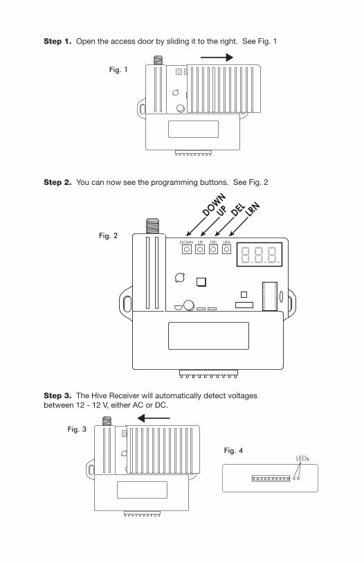
Step 2. You can now see the programming buttons. See Fig. 2
Step 3. The Hive Receiver will automatically detect voltages between 12 - 12 V, either AC or DC.
Step 1. Open the access door by sliding it to the right. See Fig. 1
DOWN
DOWN UP DEL LRN
UP DEL LRN
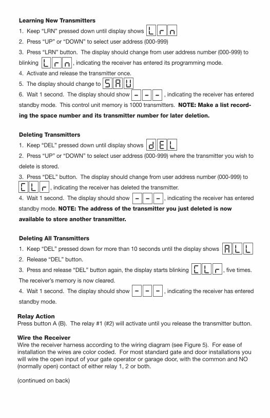
Learning New Transmitters
1. Keep “LRN” pressed down until display shows
2. Press “UP” or “DOWN” to select user address (000-999)
3. Press “LRN” button. The display should change from user address number (000-999) to
blinking , indicating the receiver has entered its programming mode.
4. Activate and release the transmitter once.
5. The display should change to
6. Wait 1 second. The display should show , indicating the receiver has entered
standby mode. This control unit memory is 1000 transmitters. NOTE: Make a list record-
ing the space number and its transmitter number for later deletion.
Deleting Transmitters
1. Keep “DEL” pressed down until display shows
2. Press “UP” or “DOWN” to select user address (000-999) where the transmitter you wish to
delete is stored.
3. Press “DEL” button. The display should change from user address number (000-999) to
, indicating the receiver has deleted the transmitter.
4. Wait 1 second. The display should show , indicating the receiver has entered
standby mode. NOTE: The address of the transmitter you just deleted is now
available to store another transmitter.
Deleting All Transmitters
1. Keep “DEL” pressed down for more than 10 seconds until the display shows
2. Release “DEL” button.
3. Press and release “DEL” button again, the display starts blinking , five times.
The receiver’s memory is now cleared.
4. Wait 1 second. The display should show , indicating the receiver has entered
standby mode.
Relay ActionPress button A (B). The relay #1 (#2) will activate until you release the transmitter button.
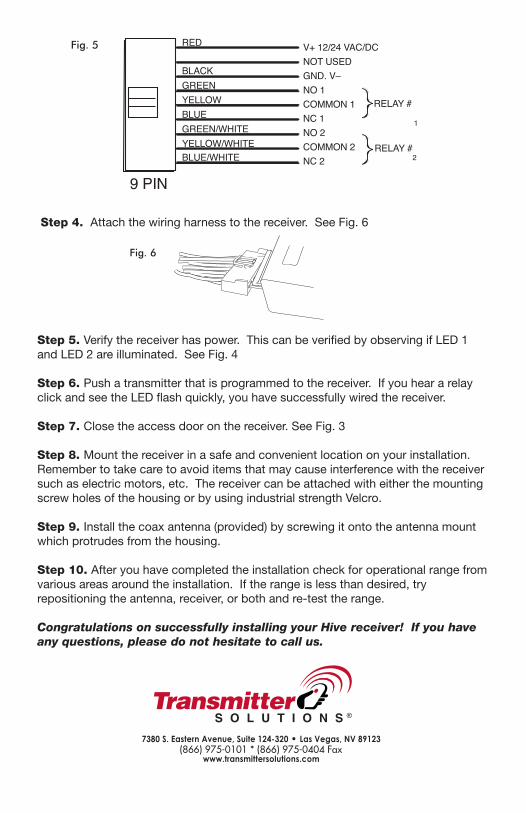
Wire the ReceiverWire the receiver harness according to the wiring diagram (see Figure 5). For ease of installation the wires are color coded. For most standard gate and door installations you will wire the open input of your gate operator or garage door, with the common and NO (normally open) contact of either relay 1, 2 or both.
(continued on back)
Step 5. Verify the receiver has power. This can be verified by observing if LED 1 and LED 2 are illuminated. See Fig. 4
Step 6. Push a transmitter that is programmed to the receiver. If you hear a relay click and see the LED flash quickly, you have successfully wired the receiver.
Step 7. Close the access door on the receiver. See Fig. 3
Step 8. Mount the receiver in a safe and convenient location on your installation. Remember to take care to avoid items that may cause interference with the receiver such as electric motors, etc. The receiver can be attached with either the mounting screw holes of the housing or by using industrial strength Velcro.
Step 9. Install the coax antenna (provided) by screwing it onto the antenna mount which protrudes from the housing.
Step 10. After you have completed the installation check for operational range from various areas around the installation. If the range is less than desired, try repositioning the antenna, receiver, or both and re-test the range.
Congratulations on successfully installing your Hive receiver! If you have any questions, please do not hesitate to call us.
Step 4. Attach the wiring harness to the receiver. See Fig. 6

User Space Number Transmitter Number Remarks000001002003004005006007008009010011012013014015016017018019020021022023024025026027028029030031032033034035036037038039040041042043044045046047048049050051052053054055056057058059060061062063064065066067068069070071072073074075076077078079080081082083084085086087088089090091092093094095096097098...999