Embed Size (px)
Citation preview

Ins t ruct ion manual
IMO Jaguar VXSM Genera l Purpose Inver te r
S ing le Phase 230V input , 0 .4-2.2kW
Three Phase 415V input , 0 .4-7.5kW

Contents
Safety Instructions i1. Before Using the Inverter 1-1
1-1 Receiving Inspection 1-11-2 Appearance of Product 1-11-3 Handling the Product 1-31-4 Transportation 1-61-5 Storage 1-6
2. Installation and Connection 2-12-1 Operating Environment 2-12-2 Installation Method 2-12-3 Connection 2-2
2-3-1 Basic Connection 2-22-3-2 Connection of Main Circuit
and Grounding Terminal 2-42-3-3 Connection of Control
Terminals 2-62-3-4 Terminal Layout 2-92-3-5 Applicable Devices and
Cable Sizes for Main Circuit 2-11
3. Operation 3-13-1 Inspection and Preparation
Before Operation 3-13-2 Operation Method 3-13-3 Test Operation 3-1
4. Keypad Panel 4-14-1 Appearance of Keypad Panel 4-1
4-1-1 Upon an Alarm 4-34-1-2 Digital Frequency Setting
Method 4-3
5. Selecting Functions 5-15-1 Function Selection List 5-15-2 Detail Description of Each
Function 5-11Fundamental Functions (F Functions) 5-11Extension Terminal Functions (E Functions) 5-21Control Functions of Frequency (C Functions) 5-26Motor Parameters (P Functions) 5-28High Performance Functions (H Functions) 5-30Alternative Motor Parameters (A Functions) 5-38Optional Functions (O Functions) 5-39
6. Protective Operation 6-16-1 List of Protective Operations 6-16-2 Alarm Reset 6-2
7. Troubleshooting 7-17-1 When Protective Function
Activates 7-17-2 When Motor rotates Incorrectly 7-5
8. Maintenance and Inspection 8-18-1 Daily Inspection 8-18-2 Periodic Inspection 8-18-3 Measurement of Current
and Voltage in Main Circuit 8-48-4 Insulation Test 8-58-5 Replacement Parts 8-58-6 Inquiries about Product and
Guarantee 8-5
9. Specifications 9-19-1 Standard Specifications 9-19-2 Common Specifications 9-39-3 External Dimensions 9-79-4 RS485 Communication 9-11
9-4-1 Connector and Communication Cable 9-12
9-4-2 Recommended RS-232C/RS485 Converter 9-12
9-4-3 Remove/local changeover 9-129-4-4 Communication Protocol 9-139-4-5 Standard Frame 9-159-4-6 Short Frame 9-169-4-7 Details of Frame 9-179-4-8 Broadcasting 9-189-4-9 Communication Error Code 9-199-4-10 Data Type 9-199-4-11 Function Code List 9-209-4-12 Data Format 9-24
10. Options 10-110-1 External Options 10-1
11. Applicable Reactor 11-112. Electromagnetic compatibility 12-1
12-1 General 12-112-2 Recommended Installation
Instructions 12-1
13. Warranty Statement 13-1Product Support Contacts


Safety Instructions i
Introduction
Safety precautionsRead through this manual before startinginstallation, connection (wiring), operation, ormaintenance and inspection for correct use. Befamiliar with the knowledge about the device,information about safety, and all the precautionsbefore starting operation.The safety precautions are classified into thefollowing categories in this manual.
WARNINGNegligence of the description cancause dangers including deaths orserious injuries.
CAUTIONNegligence of the description cancause dangers including intermediateor slight injuries or material losses.
Negligence of the description under theCAUTION title can cause serious results incertain circumstances. These safetyprecautions are important and must beobserved at all times.
Purposes
WARNING• VXSM is designed to drive a three-phase induction motor. Do not use it
for single-phase motors or for otherpurposes.
Otherwise fire could occur.
• VXSM may not be used for a life-supportsystem or other purposes directly relatedto human safety.
• Though VXSM is manufactured understrict quality control, install safety devicesfor applications where serious accidentsor material losses are foreseen in relationto the failure of it.
Otherwise accidents could occur.
Installation
WARNING• Install the inverter on anonflammable material such as metal.
Otherwise fire could occur.
• Do not place flammable matter nearby.
Otherwise fire could occur.
CAUTION• Do not hold the cover duringtransportation.
Otherwise the inverter may drop andcause injuries.
• Do not allow lint, paper, wood chips, dust,metallic chips or other foreign matter inthe inverter.
Otherwise fire or an accident couldoccur.
• Do not install or operate an inverter whichis damaged or lacking parts.
Otherwise fire, an accident or injuriescould occur.

ii Safety Instructions
Wiring
CAUTION• Check that the number of phasesand the rated voltage of the product
agree with the number of phases and thevoltage of the AC power supply. Otherwise fire or an accident couldoccur.
• Do not connect the AC power cables tothe output terminals (U, V, W).
Otherwise fire, accident or damage couldoccur.
• Do not connect a braking resistor directlyto the DC terminals (P (+), N (-)).
Otherwise fire, accident or damage couldoccur.
• The inverter, motor and wiring generateelectric noise. Take care of malfunction ofthe nearby sensors and devices.
Otherwise an accident could occur.
WARNING• When connecting the inverter to thepower supply, add a circuit breaker for
circuit protection and earth leakage breakerin the path of power supply.Otherwise fire could occur.
• This equipment must be earthed. Otherwise electric shock or fire couldoccur.
• Both screws of grounding terminals ofVXSM75-1/550-3 need to be tightened upsecurely even if one grounding terminal isnot used.
Otherwise electric shock or fire couldoccur.
• Qualified electricians should carry outwiring.
Otherwise electric shock could occur.
• Perform wiring after checking that thepower supply is turned off.
Otherwise electric shock could occur.
• Be sure to perform wiring after installingthe main body of the inverter.
Otherwise electric shock or injuriescould occur.
Operation
CAUTION• Do not turn the main circuit poweron or off to start or stop inverter
operation. Otherwise failure could occur.• Do not touch the heat sink and brakingresistor because they become very hot. Otherwise burns could occur.• Setting the inverter to high speeds iseasy. Check the performance of the motorand machines before changing the setting. Otherwise injuries could occur.• The brake function of the inverter doesnot provide mechanical holding means.
Injuries could occur.
WARNING• Be sure to install the terminal coverbefore turning the power on. Do not
remove the cover during power application. Otherwise electric shock could occur.• Do not operate switches with wet hands. Otherwise electric shock could occur.• If the retry function has been selected, the
inverter may automatically restartaccording to some causes after tripping.
(Design the machine so that human safety isensured after restarting.) Otherwise an accident could occur.• If the torque limit function has been
selected, the inverter may operate at anacceleration/deceleration time or speeddifferent from the set ones. Design themachine so that safety is ensured even insuch cases.
Otherwise an accident could occur.• The STOP key is only effective when
function setting has been established tomake the STOP key enable. Prepare anemergency stop switch separately.
Otherwise an accident could occur.• If an alarm reset is made with the
operation signal turned on, a sudden startwill occur. Check that the operation signalis turned off in advance.
Otherwise an accident could occur.• Do not touch the inverter terminals when
power to the inverter is applied even if theinverter has stopped.
Otherwise electric shock could occur.

Safety Instructions iii
Maintenance and inspection andparts replacement
Disposal
CAUTION• Handle the inverter as an industrial
waste when disposing of it.
Otherwise injuries could occur
Others
WARNING• Never remodel.
Otherwise electric shock orinjuries could occur.
WARNING• Turn the power off and wait for atleast five minutes before starting
inspection. (Further, check that the chargelamp is unlit, and check the DC voltageacross the P (+) and N (-) terminals to belower than 25Vdc.)
Otherwise electric shock could occur.
• Maintenance and inspection and partsreplacement should be made only byqualified persons. (Take off watch, ringsand other metallic matter before startingwork.) (Use insulated tools.)
Otherwise electric shock or injuriescould occur.
GENERAL PRECAUTIONSDrawings in this manual may be illustratedwithout covers or safety shields forexplanation of detail parts. Restore thecovers and shields in the original state andobserve the description in the manualbefore starting operation.
iv Safety Instructions
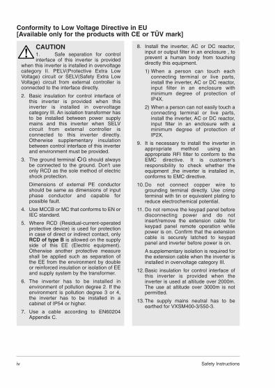
Conformity to Low Voltage Directive in EU [Available only for the products with CE or TÜV mark]
CAUTION1. Safe separation for controlinterface of this inverter is provided
when this inverter is installed in overvoltagecategory II. PELV(Protective Extra LowVoltage) circuit or SELV(Safety Extra LowVoltage) circuit from external controller isconnected to the interface directly.
2. Basic insulation for control interface ofthis inverter is provided when thisinverter is installed in overvoltagecategory III. An isolation transformer hasto be installed between power supplymains and this inverter when SELVcircuit from external controller isconnected to this inverter directly.Otherwise supplementary insulationbetween control interface of this inverterand environment must be provided.
3. The ground terminal G should alwaysbe connected to the ground. Don't useonly RCD as the sole method of electricshock protection.
Dimensions of external PE conductorshould be same as dimensions of inputphase conductor and capable forpossible fault.
4. Use MCCB or MC that conforms to EN orIEC standard.
5. Where RCD (Residual-current-operatedprotective device) is used for protectionin case of direct or indirect contact, onlyRCD of type B is allowed on the supplyside of this EE (Electric equipment).Otherwise another protective measureshall be applied such as separation ofthe EE from the environment by doubleor reinforced insulation or isolation of EEand supply system by the transformer.
6. The inverter has to be installed inenvironment of pollution degree 2. If theenvironment is pollution degree 3 or 4,the inverter has to be installed in acabinet of IP54 or higher.
7. Use a cable according to EN60204Appendix C.
8. Install the inverter, AC or DC reactor,input or output filter in an enclosure , toprevent a human body from touchingdirectly this equipment.
1) When a person can touch eachconnecting terminal or live parts,install the inverter, AC or DC reactor,input filter in an enclosure withminimum degree of protection ofIP4X.
2) When a person can not easily touch aconnecting terminal or live parts,install the inverter, AC or DC reactor,input filter in an enclosure with aminimum degree of protection ofIP2X.
9. It is necessary to install the inverter inappropriate method using anappropriate RFI filter to conform to theEMC directive. It is customer'sresponsibility to check whether theequipment ,the inverter is installed in,conforms to EMC directive.
10. Do not connect copper wire togrounding terminal directly. Use crimpterminal with tin or equivalent plating toreduce electrochemical potential.
11. Do not remove the keypad panel beforedisconnecting power and do notinsert/remove the extension cable forkeypad panel remote operation whilepower is on. Confirm that the extensioncable is securely latched to keypadpanel and inverter before power is on.
A supplementary isolation is required forthe extension cable when the inverter isinstalled in overvoltage category III.
12. Basic insulation for control interface ofthis inverter is provided when theinverter is used at altitude over 2000m.The use at altitude over 3000m is notpermitted.
13. The supply mains neutral has to beearthed for VXSM400-3/550-3.

Safety Instructions v
Caution for UL/cUL requirement[Available only for the products with UL/cUL mark]
CAUTION1. [WARNING] Take care of electricshock. Be sure to turn the inverter off
before starting work.2. [CAUTION] When the charge lamp is lit,
the inverter is still charged at adangerous voltage.
3. [WARNING] There are two or more liveparts inside the inverter.
4. The inverter is approved as a part usedinside a panel. Install it inside a panel.
5. Perform wiring to the input, output andcontrol terminals of the inverter, referringto the table below. Use UL certified roundcrimp terminal to the input and outputterminals with insulation cover orcovered with reduced tube to obtain theinsulation distance. Use a crimping toolrecommended by the terminalmanufacturer when fabricating crimpterminals.
6. Install a fuse or circuit breaker betweenthe power supply and the inverter,referring to the table below.1) Use copper wires of allowable
maximum temperature 60 or 75degree C.
2) Use UL certified AC600V "Class Jfuse."
7. The inverters VXSM40-1 to 220-1 aresuitable for use on a circuit capable ordelivering not more than 20,000 rmssymmetrical amperes, 240V maximum.
8. The inverters VXSM40-3 to 750-3 aresuitable for use on a circuit capable ordelivering not more than the followingsymmetrical amperes, 480V maximum.When a fuse is installed : 20,000AWhen a circuit breaker is installed :5000A
9. VXSM*** is an open type inverter.10. A class 2 circuit wired with class 1 wire.
Tightening torque Applicable wire[N-m] diameter [AWG] (mm2) 1)
L1/R, L2/S L1/R,L2/S L3/T Fuse 2)
Inverter type L3/T L1/L, L2/N orL1/L, L2/N Control G Control BreakerP1, P(+) section P1, P(+) section [A]DB, N(-) DB, N(-)U,V,W U,V,W
61.2
14 (2.1)6
VXSM40-10.4
20 10VXSM75-1 (0.5) 15VXSM150-1 1.8 12 (3.3) 30VXSM220-1 10 (5.3) 40VXSM40-3
6VXSM75-3VXSM150-3 1.8 14 (2.1) 20 10VXSM220-3 0.4 (0.5) 15VXSM400-3 20VXSM550-3
3.512 (3.3) 30
VXSM750-3 10 (5.3) 40

1 Before Using the Inverter1-1 Receiving InspectionUnpack and check the following items.If you have any problems with the product,contact IMO Precision Controls Ltd.(1) Check the ratings nameplate to confirm thatthe delivered product is the ordered one.
TYPE: Type of inverter
VXSM 40 -1
VersionPower voltage system:-1: Single-phase 200Vclass-3: Three-phase 400Vclass
Nominal applicable motor capacity:example40 = 0.4kW220 = 2.2kW400.= 4.0kW
Product type
1-1 Before Using the Inverter
1
SOURCE: Number of input phases, inputvoltage, input frequency, inputcurrent
OUTPUT: Number of output phases, ratedoutput capacity, rated outputvoltage, output frequency range,rated output current, overloadcurrent rating
SER. NO.: Product number
0 1 0113R0001
Serial number of production lot
Production month: 1 to 9: January to September; X, Y, or Z: October, November, or December
Production year: Last digit of year
(2) Check for breakage, missing parts, anddents or other damage on the cover and themain body given during transportation.
(3) Instruction manual for inverter is delivered withthe unit or is available on www.imopc.com.
1-2 External view of Product(1-1) Overall view (4.0kW or below)
Keypad panel mounting screw
Keypad panel
Ratings nameplate
Intermediate cover
Control terminal block cover
Main circuit terminal block cover
VXSM40-1
1PH 200-240V 50/60Hz 6.4A
010113R001
3PH 0.4kW 200-230V 0.2-400Hz 3.0A150% 1min

Before Using the Inverter 1-2
1
(1-2) Overall view (5.5,7.5kW)
(2-1) View of wiring part(4.0kW or below)
A barrier is provided in the main circuit terminalblock cover for the P1, P (+), DB and N (-) cableport. Cut the barrier before wiring.
Keypad panel mounting screw
Keypad panel
Intermediate cover
Ratings nameplate
Terminal block cover
Control cable port
P1, P (+), DB, N (-) cable port
L1/R, L2/S, L3/T(L1/L, L2/N), U, V, W cable port
Grounding cable port

1-3 Before Using the Inverter
1
(2-2) View of wiring part(5.5,7.5kW)
A barrier is provided in the cable cover for theP1, P (+), DB and N (-) cable port. Cut thebarrier before wiring.
1-3 Handling the Product(1) Removing the control terminal block
cover(4.0kW or below)
While lightly pushing the sides of the controlterminal block cover at the catches, lift the coverin the procedure shown in Fig. 1-3-1 to removeit.
Fig. 1-3-1 Removing the control terminal blockcover
Terminal block cover
Control cable port
L1/R, L2/S, L3/T cable port
P1, P (+), DB, N (-) cable port
U, V, W cable port
Cable cover
Grounding cable port

Before Using the Inverter 1-4
1
(2) Removing the main circuit terminal blockcover(4.0kW or below)
While lightly pushing the sides of the maincircuit terminal block cover at the catches, slidetoward you in the procedure shown in Fig. 1-3-2to remove it.
(3) Removing the terminal blockcover(5.5,7.5kW )
Loose the screws indicated below and whilelightly pushing the sides of the terminal blockcover at the catches, lift the cover in theprocedure shown in Fig. 1-3-3 to remove it.
Fig. 1-3-2 Removing the main circuit terminal blockcover

1-5 Before Using the Inverter
1
(4) Removing the keypad panel
Loosen the keypad panel mounting screws andremove the keypad panel in the procedureshown in Fig. 1-3-4. During the procedure,slowly remove the keypad panel right toward thetop. If the keypad panel is handled abruptly, theconnector will be broken.
Mounting screw (M3)
Fig. 1-3-4 Removing the keypad panel
Reverse the procedures to mount the terminalblock cover and keypad panel.

Before Using the Inverter 1-6
1
1-4 TransportationAlways hold the main unit when carrying theinverter.If covers or parts are held, the inverter may bebroken or it may drop.
1-5 Storage
To store temporarily
Store the inverter in an environment describedin Table 1-5-1.
Table 1-5-1 Storage environment
Item Specifications
Ambient -10~+50temperature degree C
Storage (Note 1) -25~+65 temperature degree C
Relative 5~95%humidity (Note 2)
Atmosphere The product must not be exposedto dust, direct sunlight, corrosive or flammable gases, oil mist, vapor, water drops or vibration. There must be little salt in the atmosphere.
Atmospheric 86~106kPa pressure (During storage)
70~106kPa (During transportation)
Note 1: The storage temperature is for a shorttime during transportation or the like.
Note 2: Even if the humidity is within therequirements of the specifications,places with abrupt temperaturechanges are subject to condensationor freezing. Avoid storing the inverterin such places.
(1) Do not place the inverter directly on the floor.
(2) If the ambient atmosphere is adverse,wrap the inverter in a vinyl sheet or thelike when storing.
(3) If humidity may give an ill effect, add adrying agent (such as silica gel) in thepackage prepared as described initem (2).
Places not subjectedto abrupttemperature changesor condensation orfreezing
To store for a long time
The long-term storage method of the invertervaries largely according to the environment ofthe storage site. General storage methods aredescribed below.
(1) The storage site must satisfy therequirements of specifications fortemporary storage. However, for storageexceeding three months, the upper limit ofthe ambient temperature shall not exceed30 °C. This is for the prevention ofdeterioration of electrolytic capacitors leftturned off.
(2) The package must be air tight so thatmoisture will not enter. Add a drying agentinside the package to contain the relativehumidity inside the package within 70%.
(3) The inverter installed on a unit or controlpanel and left is likely to be exposed tomoisture and dust. If this is the case,remove the inverter and move it to apreferable environment.
(4) Electrolytic capacitors left turned off for anextended period of time deteriorate. Do notstore for one year or more without turningthe power on.

2-1 Installation and Connection
2
Item Specifications
Site Indoors
Ambient -10 to +50 degree Ctemperature
Relative 5 to 95% (without condensation)humidity
Atmosphere The inverter must not be exposed to
dust, direct sunlight, corrosive
gases, oil mist, vapor or water drops.There must be little salt.No condensation occurs due toabrupt temperature changes.
Altitude 1,000 m max. (Refer to Table 2-1-2for altitudes exceeding 1000 m.)
Atmospheric 86 to 106 kPapressure
Vibration 3mm 2 to 9 Hz9.8m/s2 9 to 20 Hz2m/s2 20 to 55 Hz1m/s2 55 to 200 Hz
Impact <15g (IEC 61068-2-27)
2. Installation andConnection2-1 Operating EnvironmentInstall the inverter in an environment describedin Table 2-1-1.
Table 2-1-1 Operating environment
2-2 Installation Method(1) Securely mount the inverter in the upright
position on a rigid structure so that the"VXSM" characters face front. Avoidmounting the inverter upside down or avoidmounting horizontally.
(2) Allow clearances for cooling air shown inFig. 2-2-1 to cool down the inverter whichgenerates heat during operation. Thegenerated heat is radiated upward. Do notinstall the inverter below a heat sensitivedevice.
WARNINGInstall the inverter on a nonflammablematerial such as metal.
Otherwise fire could occur.
CAUTIONDo not allow lint, paper, wood chips,dust, metallic chips or other foreign
matter in the inverter or do not allow themattached to the heat sink. Otherwise fire or an accident could occur.
(3) The temperature of the heat sink rises toabout 90 degrees C during operation of theinverter. Mount the inverter on a base madeof a material withstanding the temperaturerise.
Fig. 2-2-1
Above
Left Right
100mm
10mm10mm
100mmBelow
VXSM
(4) When installing the inverter inside a controlpanel or the like, take full consideration forventilation so that the ambient temperatureof the inverter does not exceed thespecification requirements. Do not installthe inverter in a poorly ventilated smallenclosure.
(5) When storing multiple inverters inside asingle unit or inside a control panel,horizontal installation is recommended toreduce mutual temperature effects. Whenan vertical layout is adopted for anunavoidable reason, install a partition plateor the like between inverters to isolate theheat of the lower inverter.
Altitude Output current attenuation ratio
1000 m or less 1.00
1000-1500m 0.97
1500-2000m 0.95
2000-2500m 0.91
2500-3000m 0.88
Table 2-1-2 Output attenuation ratio in relation to altitude

Installation and Connection 2-2
2
WARNING• Be sure to connect the groundingcable before applying power.
Otherwise electric shock or fire couldoccur.• Qualified electricians should carry outwiring. Otherwise electric shock could occur.• Perform wiring after checking that thepower supply is turned off. Otherwise electric shock could occur.
2-3 ConnectionRemove the control terminal block cover toconnect the control terminal block. Remove themain circuit terminal block cover to connect themain circuit terminal block. Correctly connectcables taking care of the following precautions.
2-3-1 Basic Connection(1) Be sure to connect the power cables to
main circuit power terminals L1/R, L2/S andL3/T or L1/L,L2/N of the inverter. If thepower cables are connected to otherterminals, the inverter will be broken. Aswell, check the source voltage for theallowable voltage range specified on thenameplate and so on.
(2) Connect the grounding terminal accordingto national or local regulations to preventelectric shock, fire or other accidents and toreduce electric noise.
(3) Use reliable crimp terminals for connectionof cables to the terminals.
(4) After finishing wiring, check the following.a. Check if the cables are connected
correctly.b. Check if there is no failure of connection.c. Check if terminals or cables are short
circuited or there is a ground fault.
(5) To change connection of an inverter havingbeen turned onThe smoothing capacitor in the directcurrent part of the main circuit takes time tobe discharged after it is turned off. To avoiddanger, check the DC voltage (across maincircuit terminals P (+) and N (-)) for a safetyvoltage (25 Vdc or lower) using a multi-meter, after the charge lamp is unlit. Waituntil the residual voltage is dischargedbefore shorting a circuit, to avoid being hitby sparks caused by electric discharge.

2-3 Installation and Connection
2
*1) Supply a source voltagesuitable for the ratedvoltage of the inverter.
*2) Optional part. Use whennecessary.
*3) Peripheral equipment.Use when necessary.
*4) To connect a DC reactor(DCR) for power factorcorrecting, remove thejumper between the P1and P (+) terminals.
Basic connection diagram
Enclosure

Installation and Connection 2-4
2
2-3-2 Connection of Main Circuit and Grounding Terminal
Symbol Name of terminal Description
L1/R,L2/S,L3/T Main circuit power input Connects a 3-phase power supply.
L1/L,L2/N Main circuit power input Connects a 1-phase power supply.
U,V,W Inverter output Connects a 3-phase induction motor.
P1,P(+) For DC reactor Connects an optional DC reactor.
P(+),DB For external braking Connects an optional external braking resistor.resistor
P(+),N(-) DC link circuit terminal Connected to DC link circuit.
G grounding Grounding terminal of the inverter chassis (housing). Connect to the protective ground.
(1) Main circuit power input terminal (L1/R,L2/S, L3/T,L1/L,L2/N)a. Connect the main circuit power input
terminals to the power supply through acircuit breaker for circuit (wiring)protection or an earth leakage breaker.There is no need to match the phasesequence.
b. It is recommended to connect amagnetic contactor to disconnect theinverter from the power supply toprevent a failure or accident frombecoming serious upon activation of theprotective function of the inverter.
c. Do not turn the main circuit powersupply on or off to start or stop theinverter. Instead, use control circuitterminals FWD and REV or the RUNand STOP keys on the keypad panel. Ifit is unavoidable to turn the main circuitpower supply on or off to start or stop theinverter, limit the frequency to once anhour or fewer, if possible.
d. Do not connect to a single-phase powersupply for 3-phase input inverter.
(2) Inverter output terminals (U, V, W)a. Connect these terminals to a 3-phase
motor with the correct phase sequence.If the direction of rotation does notmatch the operation direction, changearbitrary two cables among the U, V andW phases.
b. Do not connect a phase advancecapacitor or surge absorber to theinverter output.
c. If the wiring length between the inverterand the motor is extremely long, thestray capacity between cables causes ahigh frequency current, possibly trippingthe inverter due to an overcurrent,increasing the leakage current, ordeteriorating the current detectionaccuracy to cause deterioration of theperformance or other phenomena. Toprevent such trouble, limit the wiringlength of the motor to 50 m for 4.0 kW ora smaller output or to 100 m for a largeroutput.
Note: When a thermal relay is installed in thepath between the inverter and the motor, orespecially in the case of a 400V system, thethermal relay may malfunction even with awiring length shorter than 50 m. In such a case,add an OFL filter or lower the Motor soundadjustment (carrier frequency) of the inverter. ...Function code F26 Motor sound adjustment.
Table 2-3-1 Connection of Main Circuit and Grounding Terminal

2-5 Installation and Connection
2
(3) DC reactor connecting terminals (P1, P (+))a. Use this terminal to connect a DC
reactor (option). Remove the jumperconnected in the factory beforeconnecting the DC reactor.
b. Do not remove the jumper if no DCreactor is used.Cut the barrier in the main circuitterminal block cover for the P1, P (+),DB and N (-) cable port when connectingwiring.
(4) External braking resistor connectingterminals (P (+), DB)VXSM is not equipped with a brakingresistor. An external braking resistor(option) is necessary for frequent operationor heavy duty inertia load operation toenhance the braking performance.a. Connect the P (+) and DB terminals of
the external braking resistor to the P (+)and DB terminals of the inverter.
b. Arrange devices so that the wiringlength is within 5 m and twist or closely(in parallel) place the two cables.
(5) Inverter grounding terminal ( G )Ground the grounding terminal G forsafety and noise reduction without fail. Themetallic frame of electrical equipment mustbe grounded in accordance with nationalregulations to avoid electric shock, fire andother disasters
Fig. 2-3-1 DCR connection diagram
Fig. 2-3-2 Connection diagram
Inverter
P(+)P1
DCR
CAUTION• Check that the number of phasesand the rated voltage of the product
agrees with the number of phases and thevoltage of the AC power supply.• Do not connect the AC power cables to theoutput terminals (U, V, W). Otherwise injuries could occur.• Do not connect a braking resistor directlyto the DC terminals (P (+), N (-)).Otherwise fire could occur.

Installation and Connection 2-6
2
2-3-3 Connection of Control TerminalsTable 2-3-2 shows the functions of the controlcircuit terminals. The method of connecting
control function terminals varies according tothe function setting. Refer to the connectionmethod for the function.
Table 2-3-2 Functions of control circuit terminals
Classifi- Terminal cation symbol Terminal name Description of function
13 Potentiometer power +10 Vdc power supply for frequency setting POT.supply (POT: 1 to 5 kohm).
12 Voltage input (1) The frequency is set according to the external analog input voltage command.• 0 to +10 Vdc / 0 to 100%• Reversible operation using +/- signal: 0 to +/-10 Vdc / 0 to 100%
Analog • Inverse mode operation: +10 to 0 Vdc / 0 to 100%input (2) The PID control feedback signal is input.
* Input resistance: 22 kOhm
C1 Current input (1) The frequency is set according to the analog input current command.• 4 to 20 mAdc / 0 to 100%• Inverse mode operation: 20 to 4 mAdc / 0 to 100%(2) The PID control feedback signal is input.* Input resistance 250 ohm
11 Common Common for analog signals
FWD Forward operation Forward operation with FWD-P24 ON and command deceleration and stop with FWD-P24 OFF.
REV Reverse operation Reverse operation with REV-P24 ON and command deceleration-stop with REV-P24 OFF.
X1 Digital input 1 A coast-to-stop command from an external X2 Digital input 2 device, external alarm, alarm reset, multi-step
X3 Digital input 3 frequency selection and other functions can be
X4 Digital input 4assigned to the X1 through X5 terminals. Refer to
X5 Digital input 5the terminal function E01 to 05 setting method insection 5-2 Detail Description of Each Function.<Digital input circuit specification>
Digitalinput
CM Common Common for digital input
Item min. typ. Max
Operation Level OFF 0V - 2V
voltage Level ON 22V 24V 27V
Operation current at ON - 4.2mA 6mA
Allowable leakage current at OFF - - 0.5mA

2-7 Installation and Connection
2
Classifi- Terminal cation symbol Terminal name Description of function
FM Analog monitor The monitor signal for analog DC voltage (0 to +10Vdc) is output. The signal description can be selected from the following.• Output frequency1 (before slip compensation)• Output frequency2 (after slip compensation)• Output current • Output voltage• Output torque • Load factor
Analog • Input power • PID feedback valueoutput/ • DC link circuit voltagepulse * Allowable connection impedance: min. 5 k ohmoutput Pulse rate monitor The monitor signal is output according to the pulse
voltage. The signal description is the same as the FMA signal.* Allowable connection impedance: min. 5 k ohmUse SW1 on the control board and function code F29 to change between the analog monitor and Pulse rate monitor.(FMA: analog monitor, FMP: Pulse rate monitor)
Y1E Transistor output 1 The RUN signal, frequency equivalence signal,
Y2E Transistor output 2 overload early warning signal and other signals areoutput to arbitrary ports at a transistor output. Refer to terminal function E20 to 21 setting methods in section 5-2 Detail Description of Each Function.
<Transistor output circuit specification>
Transistoroutput
CMC Common Common for transistor output signal. Isolated from (Transistor output) terminals CM and 11.
P24 DC voltage supply Power supply for transistor output load. (24 Vdc 50mAdc Max.) (When using P24, short the CMC and P24 terminals) (If the P24 terminal is overloaded or connected with the CM terminal, the inverter trips with Er3 indication. To reset, remove external causes and, after several minutes, turn the inverter on again.)
30A,30B, Alarm relay output When the inverter is stopped with an alarm, a relay30C contact output (1C) is issued.
Relay Contact capacity: 48 Vdc 0.5 Aoutput (When complying with UL/cUL:42Vdc 0.5A)
Selection between excitation upon an alarm or excitation during normal operation is possible.
Item min. typ. Max
Operation Level OFF - -1V -2V
voltage *1 Level ON - -24V -27V
Max. load current at ON - - -50mA
Leakage current at OFF - - -0.1mA
Operation Voltage
Current

Installation and Connection 2-8
2
(2) Digital input terminals (FWD, REV, X1through X5, P24)a. Generally the digital input terminals
(FWD, REV, X1-5) are turned on or off inrelation to the P24 terminal.
b. To use contact input, use a reliablecontact free from poor contact.
(3) Transistor output terminals (Y1E-Y2E,CMC)a. Circuit configuration shown in Table 2-3-
2 for transistor output is adopted. Takecare of the polarity of the external powersupply.
b. To connect a control relay, connect asurge absorbing diode across the coil ofthe relay.
(4) Othersa. Route the wiring of the control terminals
as far from the wiring of the main circuitas possible. Otherwise electric noisemay cause malfunctions.
b. Fix the control cables inside the inverterto keep them away from the live parts ofthe main circuit (such as the terminalblock of the main circuit).
(1) Analog input terminals (13, 12, C1, 11) a. Because weak analog signals are
handled, these signals are especiallysusceptible to external noise effects.Route the wiring as short as possible(within 20 m) and use shielded cables. Inprinciple, ground the shield of theshielded cable; if effects of externalinductive noises are considerable,connection to terminal 11 may beeffective.
b. Use twin contacts relay for weak signalsif relay is used in the circuit. Do not adda contact to terminal 11.
c. When the inverter is connected with anexternal device outputting the analogsignal, a malfunction may be caused byelectric noise generated by the inverteraccording to some type of the circuit ofthe device. If this happens, connect aferrite core or capacitor to the deviceoutputting the analog signal.
WARNINGIf the control cables touch the live partof the main circuit, the insulation
sheath of the control cable, insulation ofwhich is not reinforced, may be broken tocause a high voltage of the main circuit to befed to the control signal. This is banned inthe low voltage directive models for Europe.Electric shock could occur.
CAUTIONElectric noise may be generated by theinverter, motor or wiring. Take care of
malfunctions of the nearby sensors and devices. An accident could occur.
Fig. 2-3-4 Countermeasure against electric noise(example)
Fig. 2-3-3

2-9 Installation and Connection
2
2-3-4 Terminal Layout
(1) Main circuit terminal block
Inverter type Main circuit terminal drawing
VXSM40-1
Screw size : M3.5Tightening torque : 1.2N.m
VXSM75-1
Screw size : M4Tightening torque : 1.8N.m
VXSM40-3VXSM75-3VXSM50-3VXSM220-3
Screw size : M4Tightening torque : 1.8N.m
VXSM150-1VXSM220-1
Screw size : M4Tightening torque : 1.8N.m
VXSM400-3
Screw size : M4Tightening torque : 1.8N.m
L1/L L2/N U V W
DB P1 P(+) N(-)
G G
G G
L1/L L2/N U V W
DB P1 P(+) N(-)G G
L1/R L2/S L3/T U V W
DB P1 P(+) N(-)G G
L1/L L3/N DB P1 P(+) N(-) U V W
G G
L1/R L2/S L3/T DB P1 P(+) N(-) U V W

Installation and Connection 2-10
2
Inverter type Main circuit terminal drawing
VXSM550-3VXSM750-3
Screw size : M5Tightening torque : 3.5N.m
G G
L1/R L2/S L3/T DB P1 P(+) N(-) U V W
(1) Main circuit terminal block(Continued)
(2) Control terminal block
Screw size: M2.5Tightening torque: 0.4N◊m
30A 30B Y1E C1 FM X1 X2 X3 X4 X5 CM
30C Y2E CMC 11 12 13 CM FWD REV CM P24

2-11 Installation and Connection
2
*1 The applicable frame and series of the model ofthe molded case circuit breaker (MCCB) andearth leakage breaker (ELCB) vary according tothe capacity of the transformer of the equipment.For details of selection, refer to the relevanttechnical documents.
*2 The recommended cable size for the main circuitis PVC cable at ambient temperature 40 degreeC specified in Appendix C of EN 60204
*3 The power supply impedance without a reactoris considered to be the equivalent of 0.1% of theinverter capacity, with 10% current unbalanceaccompanied by the voltage unbalance.
*4 Use crimp terminals with an insulating cover.
2-3-5 Applicable Devices and Cable Sizes for Main Circuit
Molded case circuit Recommended wire size [mm2]breaker (MCCB) or
Nominal earth leakage Input circuit*2 Output DCR*2
Inverter applied circuit breaker [L1/R,L2/S,L3/T] circuit*2 circuit Controltype motor (ELCB)*1 [L1/L, L2/N] [U, V, W] [P1] wiring
[kW] Rated current [A] G [P(+)]
With Without With Without DBDCR reactor*3 DCR reactor*3
VXSM40-1 0.4 6 102.5
VXSM75-1 0.75 10 16 2.5 2.50.5
VXSM150-1 1.5 16 25 42.5
2.5VXSM220-1 2.2 25 32 4 6 (DB)
4(Others)
VXSM40-3 0.46
VXSM75-3 0.75 6
VXSM150-3 1.5 10
VXSM220-3 2.2 10 16 2.5 2.5 2.5 2.5 0.5
VXSM400-3 4.0
VXSM550-3 5.5 16 25 4
VXSM750-3 7.5 20 32 6
Table 2-3-4 Selection of peripheral devices
Operation 3-1
3
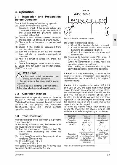
3. Operation3-1 Inspection and PreparationBefore OperationCheck the following before starting operation.(1) Check if connection is correct.
Especially check if the power cables areconnected to inverter output terminals U, Vand W and that the grounding cable isgrounded without fail.
(2) Check for short circuits between terminalsand exposed live parts and ground faults.
(3) Check for loose terminals, connectors andscrews.
(4) Check if the motor is separated frommechanical equipment.
(5) Turn the switches off so that the inverterdoes not start or operate erroneously atpower-on.
(6) After the power is turned on, check thefollowing.
a. Check if the keypad panel shows an alarm.b. Check if the fan built in the inverter rotates.(1.5 kW or above)
3-2 Operation MethodThere are various operation methods. Refer tochapter 4 "Keypad Panel" and chapter 5"Selecting Functions" to select the method mostsuitable for the purpose and operationspecification. Table 3-2-1 shows generaloperation methods.
3-3 Test OperationAfter checking for errors in section 3-1, performa test operation.In the factory shipment state, the inverter is inthe keypad panel operation mode.(1) Turn the power on and check that the LED
blinks while indicating the 0.00 Hzfrequency.
(2) Using the key, set the frequency to a lowfrequency such as 5 Hz.
(3) To turn forward: F02 = 2To reverse: F02 = 3
After setting the above, press the key to startoperation. To stop, press the key.
Fig. 3-1-1 Inverter connection diagram
Table 3-2-1 General operation methods
WARNING• Be sure to install the terminal coverbefore turning the power on.
• Do not remove the cover during powerapplication.• Do not operate switches with wet hands. Otherwise electric shock could occur.
(4) Check the following points.a. Check if the direction of rotation is correct.b. Check for smooth rotation without motor
humming or excessive vibration.c. Check for smooth acceleration and
deceleration.(5) Referring to function code P04 Motor 1
(auto tuning), tune the motor constant.When no abnormality is found, raise theoperation frequency to check.After checking for correct operation during theabove test operation, start normal operation.
Caution 1: If any abnormality is found to theinverter or motor, immediately stop operationand determine the cause referring to chapter 7Troubleshooting.
Caution 2: If voltage is applied to the L1/R, L2/Sand L3/T or L1/L and L2/N main circuit powersupply terminals even after the inverter stops,the inverter output terminals U, V and W are liveand you will receive electric shock whentouching the terminals. As well, the smoothingcapacitor is not discharged immediately afterthe power is turned off and it takes time for thecapacitor to be discharged.To touch the electric circuit after turning thepower off, check that the charge lamp is unlitand check for safe voltage using a multimeter.
Operation Frequency Operationmethod setting command
Operation Keypad keypad panelusing keypad panel keys keys
panel, ,
Contact input, (switch),Operation Potentiometer terminals FWD-
using external or analog voltage P24, terminalssignal terminal current or REV-P24
multistep speedoperation
V
RUN STOPV
V
V
V
RUN
STOP

➀ Digital displayVarious function codes and data codes forprogramming are shown.The output frequency, output current andother data are displayed during operation,and the cause of a trouble is displayedusing codes when protective functionworks.
➁ Program (PRG)/RESET keyPress this key to switch over between theregular operation mode and programmingmode. Use this key to reset an alarmstopping state after activation of a protectivefunction.
➂ Unit and operation mode displayThe unit of the data displayed at the digitaldisplay is indicated with an LED. Theprogram mode is indicated. The PANELCONTROL lamp lights up in the keypadpanel operation mode.
➃ RUN keyPress this key to start operation. An LEDlights up during operation. When data code
= , the key does notfunction.
➄ STOP keyPress this key to stop operation. When datacode = , this key does notfunction.
➅ Up/down keysPress these keys to increase or decreasethe frequency or speed.In the programming mode, use these keysto change the function code or data setting.
➆ Function/Data keyUse this key to switch over betweenfrequency display, output current displayand other display in the regular operationmode. In the programming mode, use thiskey to retrieve or write various functioncodes and various function data.
120F
120F
4-1 Keypad Panel
4
(1) Monitor display modeIn the regular operation mode, press thekey to switch between frequencydisplay, output current display and otherdisplay.
4. Keypad PanelThe keypad panel is provided with variousfunctions such as operation (frequency settingand start/stop commands) from the keypadpanel, monitor and alteration of function codedata, and various confirmation functions.Be familiar with the operation method of eachfunction before starting operation.
4-1 Appearance of Keypad Panel
➀ ➁
➆
➂
➅
➃
➄
FUNCDATA
Output frequency *1
000.6
Output current *2
021.
Output voltage *2
002
Synchronizationrotation speed *2
0001
Line speed *2
0001
*1: In the PID control mode (when function H20is at "1" or "2"), the value is in the percentdisplay and the dot at the least significantdigit always lights up.
Example: 10%: , 100%:
*2: Press the , key during display ofthese data to display the frequency setting.
0.0.010.0.1
V
V
Keypad Panel 4-2
4
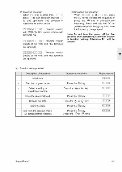
(4) Function setting method
(2) Stopping operationWhen is other than press to start operation or press ito stop operation. The direction ofrotation is as shown below.
= : Forward rotationwith FWD-CM ON, reverse rotation withREV-CM ON
= : Forward rotation(Inputs at the FWD and REV terminalsare ignored.)
= : Reverse rotation(Inputs at the FWD and REV terminalsare ignored.)
320F
220F
020F
120F
Description of operation Operation procedure Display result
Initial state
- Start the program mode. Press the key.
- Select a setting or Press the or key.monitoring function
- Have the data displayed. Press the key.
- Change the data. Press the or key.
- Store the data. Press the key.
- Exit from the program mode. Press the key.(Or select another function.) (Press the or key.)
000.6
20F
2
1
10F
00F
000.6
PRGRESET
PRGRESET
V
RUN STOP
FUNCDATA
FUNCDATA
V
V
V
V
V
(3) Changing the frequencyWhen is at , press the key to increase the frequency orpress the key to decrease thefrequency. Press and hold the or i key and press the key to increasethe frequency change speed.
Note) Do not turn the power off for fiveseconds after performing a monitor changeor function setting. Otherwise Er1 will becaused.
010F
FUNCDATAV
V
V
V

4-3 Keypad Panel
4
(5) Changing the function codeThe function code consists of an alphabeticcharacter and a numeral. The alphabeticcharacter is defined for each of the functiongroups.
Table 4-1-1 Major groups of function codes
Function code Function
F00~F42 Fundamental functions
E01~E41 Extension terminal functions
C01~C33 Control functions of frequency
P01~P10 Motor parameters
H01~H46 High performance functions
A01~A19 Alternative motor parameters
The function code changes each time the or key is pressed. (Press andhold the or key to continue to changethe function code.)While pressing and holding the ior key during function code change,press the key to change to the nextgroup with another alphabetic character.(Press the and keys to jump to thetop of the F, E, C, P, H or A code, or pressthe and key to jump to the last of theF, E, C, P, H or A code.)
Changing example:
+
+
4-1-1 Upon an AlarmWhen an alarm occurs, the descriptionof the alarm is displayed. Press the ior key during alarm display to displaythe latest three alarms.To display previous 4 alarms, selectfunction (Refer to H02 Triphistory.)
20H
24E13C
23C33C
10E20F
10F00F
4-1-2 Digital Frequency Setting MethodPress the or key at the operationmode screen. The LED display changesto the frequency setting, and the dataincreases or decreases in the unit of theleast increment first. While the or ikey is held down, the changing digitmoves to the upper order for fastchanges. Further, while pressing andholding down the or key, pressthe key to increase the changingspeed further. No special operation isnecessary to store the new frequencysetting. The setting is automaticallystored when the inverter is turned off.
FUNCDATA
V
V
PRGRESET
PRGRESET
PRGRESET
VV
V
V
V
V
V
PRGRESET
V
V V
V
V
V
V
V
V
V
PRGRESETV
V V
Description of change during operation: The data changed by the or keytakes effect on the inverter operation.However, press the key to store the newdata.
Selecting Functions 5-1
5
V
V
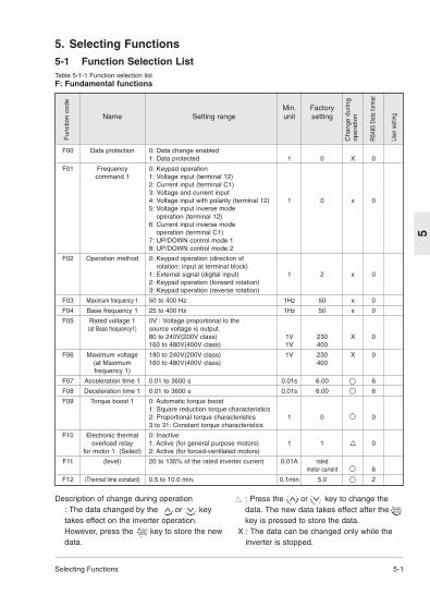
5. Selecting Functions5-1 Function Selection ListTable 5-1-1 Function selection listF: Fundamental functions
Min. FactoryName Setting range unit setting
F00 Data protection 0: Data change enabled1: Data protected 1 0 X 0
F01 Frequency 0: Keypad operationcommand 1 1: Voltage input (terminal 12)
2: Current input (terminal C1)3: Voltage and current input4: Voltage input with polarity (terminal 12) 1 0 x 05: Voltage input inverse mode
operation (terminal 12)6: Current input inverse mode
operation (terminal C1)7: UP/DOWN control mode 18: UP/DOWN control mode 2
F02 Operation method 0: Keypad operation (direction of rotation: input at terminal block)
1: External signal (digital input) 1 2 x 02: Keypad operation (forward rotation)3: Keypad operation (reverse rotation)
F03 Maximum frequency 1 50 to 400 Hz 1Hz 50 x 0
F04 Base frequency 1 25 to 400 Hz 1Hz 50 x 0
F05 Rated voltage 1 0V : Voltage proportional to the (at Base frequency1) source voltage is output.
80 to 240V(200V class) 1V 230 X 0160 to 480V(400V class) 1V 400
F06 Maximum voltage 180 to 240V(200V class) 1V 230 X 0(at Maximum 160 to 480V(400V class) 400frequency 1)
F07 Acceleration time 1 0.01 to 3600 s 0.01s 6.00 6
F08 Deceleration time 1 0.01 to 3600 s 0.01s 6.00 6
F09 Torque boost 1 0: Automatic torque boost1: Square reduction torque characteristics2: Proportional torque characteristics 1 0 03 to 31: Constant torque characteristics
F10 Electronic thermal 0: Inactiveoverload relay 1: Active (for general purpose motors) 1 1 0
for motor 1 (Select) 2: Active (for forced-ventilated motors)
F11 (level) 20 to 135% of the rated inverter current 0.01A ratedmotor current 6
F12 (Thermal time constant) 0.5 to 10.0 min. 0.1min 5.0 2
Fun
ctio
n co
de
Cha
nge
durin
g op
erat
ion
RS48
5 Da
ta fo
rmat
User
set
ting
: Press the or key to change thedata. The new data takes effect after thekey is pressed to store the data.
X : The data can be changed only while theinverter is stopped.
V
V
FUNCDATA
FUNCDATA

Min. FactoryName Setting range unit setting
F13 Electronic thermal 0: Inactiveoverload relay 1: Active (for external braking resistor
(for braking resistor) DB__-2C/4C) 1 0 X 02: Active (for external braking resistor TK80W : 0.1 to 2.2E11S-7DB__-4C : 0.4 to 7.5E11S-4)
F14 Restart mode 0:Inactive (The inverter immediately after momentary trips upon power failure.)
power failure 1:Inactive (The inverter trips after the power failure is recovered.)2:Active (The inverter restarts at the 1 0 X 0frequency effective at the time of power failure.)3:Active (The inverter restarts at the starting frequency.)
F15 Frequency limiter(High) 0 to 400 Hz 1Hz 70 0
F16 (Low) 0 0
F17 Gain (For frequency setting
signal) 0.0 to 200.0% 0.1% 100.0 2
F18 Bias frequency -400 to +400Hz 1Hz 0 1
F20 DC brake (Starting frequency) 0.0 to 60.0Hz 0.1Hz 0.0 2
F21 (Braking level) 0 to 100% 1% 0 0
F22 (Braking time) 0.0 s (Inactive)0.1 to 30.0s 0.1s 0.0 2
F23 Starting frequency(Freq.) 0.1 to 60.0Hz 0.1Hz 0.5 X 2
F24 (Holding time) 0.0 to 10.0s 0.1s 0.0 X 2
F25 Stop frequency 0.1 to 6.0Hz 0.1Hz 0.2 X 2
Motor sound (Carrier frequency) 0.75,1 to 15kHz 1kHz 15 0
(Sound tone) 0 to 3 1 0 0
5-2 Selecting Functions
5Description of change during operation
: The data changed by the or key takeseffect on the inverter operation. However,press the key to store the new data.
V
V
Fun
ctio
n co
de
Cha
nge
durin
g op
erat
ion
RS48
5 Da
ta fo
rmat
: Press the or key to change the data.The new data takes effect after the key ispressed to store the data.
X : The data can be changed only while theinverter is stopped.
V
V
FUNCDATA
FUNCDATA
User
set
ting
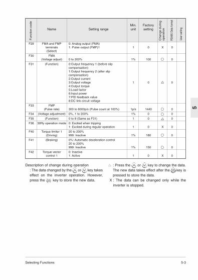
Selecting Functions 5-3
5
Min. FactoryName Setting range unit setting
F29 FMA and FMP 0: Analog output (FMA)terminals 1: Pulse output (FMP)1 1 0 X 0(Select)
F30 FMA(Voltage adjust) 0 to 200% 1% 100 0
F31 (Function) 0:Output frequency 1 (before slip compensation)1:Output frequency 2 (after slip compensation)2:Output current3:Output voltage 1 0 04:Output torque5:Load factor6:Input power7:PID feedback value8:DC link circuit voltage
F33 FMP(Pulse rate) 300 to 6000p/s (Pulse count at 100%) 1p/s 1440 0
F34 (Voltage adjustment) 0%, 1 to 200% 1% 0 0
F35 (Function) 0 to 8 (Same as F31) 1 0 0
F36 30Ry operation mode 0: Excited when tripping1: Excited during regular operation 1 0 X 0
F40 Torque limiter 1 20 to 200%(Driving) 999: Inactive 1% 180 0
F41 (Braking) 0%: Automatic deceleration control20 to 200%999: Inactive 1% 150 0
F42 Torque vector 0: Inactivecontrol 1 1: Active 1 0 X 0
Description of change during operation: The data changed by the or key takeseffect on the inverter operation. However,press the key to store the new data.
V
V
Fun
ctio
n co
de
Cha
nge
durin
g op
erat
ion
RS48
5 Da
ta fo
rmat
: Press the or key to change the data.The new data takes effect after the key ispressed to store the data.
X : The data can be changed only while theinverter is stopped.
V
V
FUNCDATA
FUNCDATA
User
set
ting

5-4 Selecting Functions
5
Min. FactoryName Setting range unit setting
E01 X1 terminal function 0: Multistep frequency selection [SS1] 0 X 01: Multistep frequency selection [SS2]2: Multistep frequency selection [SS4]3: Multistep frequency selection [SS8]
E02 X2 terminal function 4:Acceleration/deceleration time 1 X 0selection [RT1]5: 3-wire operation stop command [HLD]6: Coast-to-stop command [BX]7: Alarm reset [RST]E03 X3 terminal function8: Trip command(External fault) [THR]
2 X 0
9: Frequency setting 2/1 [Hz2/Hz1] 110: Motor 2/ Motor 1 [M2/M1]11: DC brake command [DCBRK]12: Torque limiter 2/Torque limiter 1 E04 X4 terminal function[TL2/TL1]
6 X 0
13: UP command [UP]14: DOWN command [DOWN]15: Write enable for KEYPAD [WE-KP]
E05 X5 terminal function 16: PID control cancel [Hz/PID] 7 X 017: Inverse mode changeover [IVS] (terminal 12 and C1) 18: Link enable [LE]
E10 Acceleration time 2 0.01 to 3600s 0.01s 10.0 6E11 Deceleration time 2 10.0 6E16 Torque limiter 2 20 to 200% 1% 180 0
(Driving) 999: InactiveE17 (Brake) 0%: Automatic deceleration control,
20 to 200% 1% 150 0999: Inactive
E20 Y1 terminal function 0: Inverter running [RUN] 0 X 01: Frequency equivalence [FAR]2: Frequency level detection [FDT]3: Undervoltage detection signal [LV]4: Torque polarity [B/D] 1
E21 Y2 terminal function 5: Torque limiting [TL] 7 X 06: Auto restarting [IPF]7: Overload early warning [OL]78:Life time alarm [LIFE]9:Frequency level detection 2 [FAR2]
E29 Frequency level 0.01 to 10.0s 0.01s 0.1 6detection delay
E30 FAR function signa l0.0 to 10.0Hz 0.1Hz 2.5 2(Hysteresis)
E31 FDT function signal 0 to 400Hz 1Hz 50 0(Level)
E32 (Hysteresis) 0.0 to 30.0Hz 0.1Hz 1.0 2E33 OL function signal 0: Electronic thermal overload relay
(Mode select) 1: Output current 1 0 0E34 (Level) 20 to 200% of the rated inverter current 0.01A rated
motorcurrent 6
E35 (Timer ) 0.0 to 60.0s 0.1s 10.0 2E40 Display coefficient
A 0.00 to 200.0 0.01 0.01 6E41 B 0.00 to 200.0 0.01 0.00 6E42 LED display filter 0.0 to 5.0s 0.1s 0.5 2
Fun
ctio
n co
de
Cha
nge
durin
g op
erat
ion
RS48
5 Da
ta fo
rmat
User
set
ting
E: Extension terminal functions

Selecting Functions 5-5
5
Min. FactoryName Setting range unit setting
C01 Jump frequency(Jump freq. 1) 0 to 400Hz 1Hz 0 0
C02 (Jump freq. 2) 0 0C03 (Jump freq. 3) 0 0C04 (Hysteresis) 0 to 30Hz 1Hz 3 0C05 Multistep frequency
setting (Freq. 1) 0.00 to 400.0Hz 0.01Hz 0.00 4C06 (Freq. 2) 0.00 4C07 (Freq. 3) 0.00 4C08 (Freq. 4) 0.00 4C09 (Freq. 5) 0.00 4C10 (Freq. 6) 0.00 4C11 (Freq. 7) 0.00 4C12 (Freq. 8) 0.00 4C13 (Freq. 9) 0.00 4C14 (Freq. 10) 0.00 4C15 (Freq. 11) 0.00 4C16 (Freq. 12) 0.00 4C17 (Freq. 13) 0.00 4C18 (Freq. 14) 0.00 4
C19 (Freq. 15) 0.00 4C21 Timer operation 0: Inactive 1 0 X 0
1: ActiveC22 Stage 1 0.00 to 3600s 0.01s 0.00 6C30 Frequency command 2 0 to 8 (Same as F01) 1 2 X 0C31 Analog setting signal -5.0 to +5.0% 0.1% 0.0 3
offset adjustment(Terminal 12)
C32 (Terminal C1) -5.0 to +5.0% 0.1% 0.0 3C33 Analog setting 0.00 to 5.00s 0.01s 0.05 4
signal filter
Fun
ctio
n co
de
Cha
nge
durin
g op
erat
ion
RS48
5 Da
ta fo
rmat
User
set
ting
C: Control functions of frequency
Description of change during operation: The data changed by the or key takeseffect on the inverter operation. However,press the key to store the new data.
V
V
: Press the or key to change the data.The new data takes effect after the key ispressed to store the data.
X : The data can be changed only while theinverter is stopped.
V
V
FUNCDATA
FUNCDATA

5-6 Selecting Functions
5
Min. FactoryName Setting range unit setting
P01 Number of motor 1 2 to 14 2 4 X 0poles
P02 Motor1 (Capacity) 0.01 to 5.5kW (4.0kW or less) Nominal0.01 to 11.00kW(5.5/7.5kW) 0.01kW applied X 4
motor kWP03 (Rated current) 0.00 to 99.9A 0.01A standard X 6
ratingP04 _Tuning) 0: Inactive
1: Active (%R1, %X)2: Active (%R1, %X, Io) 1 0 X 12
P05 (Online tuning) 0: Inactive1: Active 1 0 X 0
P06 (No-load current) 0.00 to 99.9A 0.01A standard X 6rating
P07 _R1 setting_ 0.00 to 50.00% 0.01% standard 4rating
P08 _X setting_ 0.00 to 50.00% 0.01% standard 4rating
P09 (Slip compensation 0.00 to 15.00Hz 0.01Hz 0.00 4control 1)
P10 (Slip compensation 0.01 to 10.00s 0.01s 0.50 4response time 1)
Fun
ctio
n co
de
Cha
nge
durin
g op
erat
ion
RS48
5 Da
ta fo
rmat
User
set
ting
P: Motor parameters
Description of change during operation: The data changed by the or key takeseffect on the inverter operation. However,press the key to store the new data.
V
V
: Press the or key to change the data.The new data takes effect after the key ispressed to store the data.
X : The data can be changed only while theinverter is stopped.
V
V
FUNCDATA
FUNCDATA

Selecting Functions 5-7
5
Min. FactoryName Setting range unit setting
H01 Total operation time Monitor only 10h 0 - 0H02 Trip history Monitor only - ---- -H03 Data initializing 0: Manual set value 1 0 X 0
(Data reset) 1: Return to factory set valueH04 Auto-reset (Times) 0: Inactive 1 to 10 times 1 time 0 0H05 (Reset interval) 2 to 20s 1s 5 0H06 Fan stop operation 0: Inactive 1 0 0
1: ActiveH07 ACC/DEC pattern 0: Linear acceleration/deceleration 1 0 X 0
(Mode select). 1:S-curve acceleration/deceleration (weak)2:S-curve acceleration/deceleration (strong)3: Non-linear
H09 Start mode 0: Inactive 1 1 X 0(Rotating motor1: Active (only when Auto-restart after
pickup mode) momentary power failure mode)2: Active (All start mode)
H10 Energy-saving 0: Inactive 1 0 0operation 1: Active
H11 Dec mode 0: Normal 1 0 01: Coast-to-stop
H12 Instantaneous 0: Inactive 1 1 X 0overcurrent limiting 1: Active
H13 Auto-restart 0.1 to 5.0s 0.1s 0.1 X 2(Restart time)
H14 (Frequency fall rate) 0.00 to 100.0Hz/s 0.01Hz/s 10.00 4H20 PID control 0: Inactive 1 0 X 0
(Mode select) 1: Forward operation2: Reverse operation
H21 (Feedback signal) 0: Terminal 12 (0 to +10 Vdc) input 1 1 X 01: Terminal C1 (4 to 20 mA) input2: Terminal 12 (+10 to 0 Vdc) input3: Terminal C1 (20 to 4 mA) input
H22 P (Gain) 0.01 to 10.00 times (1 to 1000%) 0.01 time 0.10 4H23 I (Integral time) 0.0: Inactive 0.1s 0.0 2
0.1 to 3600sH24 D (Differential time) 0.00: Inactive 0.01s 0.00 4
0.01 to 10.0sH25 (Feedback filter) 0.0 to 60.0s 0.1s 0.5 2H26 PTC thermistor 0: Inactive 1 0 0
(Mode select) 1: ActiveH27 (Level) 0.00Å`5.00V 0.01V 1.60 4H28 Droop operation -9.9Å`0.0Hz 0.1Hz 0.0 3
Fun
ctio
n co
de
Cha
nge
durin
g op
erat
ion
RS48
5 Da
ta fo
rmat
User
set
ting
H: High performance functions
Description of change during operation: The data changed by the or key takeseffect on the inverter operation. However,press the key to store the new data.
V
V
: Press the or key to change the data.The new data takes effect after the key ispressed to store the data.
X : The data can be changed only while theinverter is stopped.
V
V
FUNCDATA
FUNCDATA

5-8 Selecting Functions
5
Min. FactoryName Setting range unit setting
H30 Serial link Monitor, Frequency , Operation(Function select) setting command
0: X X 1 0 01: X2: X3:
H31 RS485 1 to 31 1 1 X 0(Address)
H32 (Mode select on 0: Immediate Er8 1 0 0no response error) 1: Er8 after interval set by timer
2: Retry in interval set by timer (Er8 after failure to restore)3: Continuation of operation
H33 (Timer) 0.0 to 60.0s 0.1s 2.0 2H34 (Baud rate) 0:19200[bit/s] 1 1 0
1:96002:48003:24004:1200
H35 (Data length) 0:8bit 1 0 01:7bit
H36 (Parity check) 0: None 1 0 01: Even parity2: Odd parity
H37 (Stop bits) 0: 2 bits 1 0 01: 1 bit
H38 (No response error 0: Not detected 1s 0 0detection time) 1 to 60s
H39 (Response interval) 0.00 to 1.00s 0.01s 0.01 4H40 Maximum Monitor only degree C - - 0
temperatureof heat sink
H41 Maximum Monitor only A - - 6effective current
H42 Main circuit Monitor only 0.1% - - 0capacitor life
H43 Cooling fan Monitor only 10h - - 0operation time
H44 Inverter ROM version Monitor only - - - 0H45 Keypad panel Monitor only - - - 0
ROM versionH46 Option ROM version Monitor only - - - 0
Fun
ctio
n co
de
Cha
nge
durin
g op
erat
ion
RS48
5 Da
ta fo
rmat
User
set
ting
Description of change during operation: The data changed by the or key takeseffect on the inverter operation. However,press the key to store the new data.
V
V
: Press the or key to change the data.The new data takes effect after the key ispressed to store the data.
X : The data can be changed only while theinverter is stopped.
V
V
FUNCDATA
FUNCDATA

Selecting Functions 5-9
5
Min. FactoryName Setting range unit setting
A01 Maximum frequency 2 50 to 400Hz 1Hz 50 X 0A02 Base frequency 2 25 to 400Hz 1Hz 50 X 0A03 Rated voltage 2 0V, 80 to 240V(200V class) 1V 230 X 0
(at base frequency 2) 0V,160 to 480V(400V class) 400A04 Maximum voltage 2 80 to 240V (200V class) 1V 230 X 0
(at maximum 160 to 480V(400V class) 400frequency 2)
A05 Torque boost 2 0,1,2,3 to 31 1 0 0A06 Electronic thermal 0: Inactive 1 1 0
overload relay 1: Active (for general purpose motors)for motor 2 (Select) 2: Active (for inverter motors)
A07 (level) 20 to 135% of the rated inverter current 0.01A rated 6motor current
A08 (Thermal time 0.5 to 10 min. 0.1min 5.0 2constant)
A09 Torque vector control 0:Inactive 1 0 X 02 1:Active
A10 Number of motor 2 to 14 2 4 X 02 poles
A11 Motor 2 (Capacity) 0.01 to 5.5kW (4.0kW or smaller) 0.01kW Nominal kW X 40.01 to 11.00kW(5.5/7.5kW) applied
motor kW A12 (Rated current) 0.00 to 99.9A 0.01A standard X 6
rating
A13 (Tuning) 0: Inactive1: Active (%R1, %X)2: Active (%R1, %X, Io) 1 0 X 12
A14 (Online tuning) 0: Inactive, 1: Active 1 0 X 0
A15 (No-load current) 0.00 to 99.9A 0.01A standard X 6rating
A16 _R1 setting_ 0.00 to 50.00% 0.01% standard 4rating
A17 _X setting_ 0.00 to 50.00% 0.01% standard 4rating
A18 (Slip compensation 0.00 to 15.00Hz 0.01Hz 0.00 4control 2)
A19 (Slip compensation 0.01 to 10.00s 0.01s 0.50 4response time 2)
Fun
ctio
n co
de
Cha
nge
durin
g op
erat
ion
RS48
5 Da
ta fo
rmat
User
set
ting
Description of change during operation: The data changed by the or key takeseffect on the inverter operation. However,press the key to store the new data.
V
V
: Press the or key to change the data.The new data takes effect after the key ispressed to store the data.
X : The data can be changed only while theinverter is stopped.
V
V
FUNCDATA
FUNCDATA
A: Alternative motor parameters
5-10 Selecting Functions
5
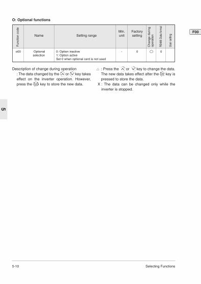
Min. FactoryName Setting range unit setting
o00 Optional 0: Option inactive - 0 0 selection 1: Option active
Set 0 when optional card is not used
Fun
ctio
n co
de
Cha
nge
durin
g op
erat
ion
RS48
5 Da
ta fo
rmat
User
set
ting
Description of change during operation: The data changed by the or key takeseffect on the inverter operation. However,press the key to store the new data.
V
V
: Press the or key to change the data.The new data takes effect after the key ispressed to store the data.
X : The data can be changed only while theinverter is stopped.
V
V
FUNCDATA
FUNCDATA
O: Optional functions
F00

Selecting Functions 5-11
5
Operation method
• The operation input method is set. (Note:This function can be changed only when theFWD and REV terminals are open.)
0: The motor starts or stops upon keypadoperation ( or key).
F02
5-2 Detail Description of EachFunction
F: Fundamental functions
Data protection
• The setting data can be protected againstinadvertent operation at the keypad panel.
0: Data change enabled1: Data protected[Setting method]01: Press the + keys simultaneously.10: Press the + keys simultaneously.
Frequency command 1
• The frequency setting method can beselected.
0: The frequency is set by the operation of Iand keys.
1: The frequency is set by the voltage input(at terminal 12) (0 to +10 Vdc).
2: The frequency is set by the current input (atterminal C1) (4 to 20 mAdc).
3: The frequency is set by the voltage inputand current input (terminal 12 and terminalC1) ((-10 to +10 Vdc) + (4 to 20 mAdc)).Inputs at terminals 12 and C1 are added todetermine the frequency.
4: The frequency is set by the voltage input withpolarity (at terminal 12) (-10 to +10 Vdc).In the case of input with polarity, operationat a direction opposite to the operationcommand is possible.
5: The frequency is set by voltage inputinverse mode operation (at terminal 12)(+10 to 0 Vdc).
6: The frequency is set by current inputinverse mode operation (at terminal C1) (20to 4 mAdc).
7: UP/DOWN control mode 1The frequency is set by terminal UP,terminal DOWN. (initial value = 0)
8: UP/DOWN control mode 2The frequency is set by terminal UP,terminal DOWN (initial value = last valueduring previous operation).Refer to the description of the E01 to E05functions for details.
F01
F00
STOP
V
STOP V
V
V
RUN STOP
Description of forward and reverse operation
The direction of rotation is determined bythe FWD and REV terminals on the controlterminal block as follows.FWD-P24 short-circuited:Forward rotationREV-P24 short-circuited: Reverse rotationThe motor does not start if both the FWDand REV terminals are connected with theP24 terminal or both of them are open.
1: External signal (digital input)The motor starts or stops upon the state ofthe FWD and REV terminals on the controlterminal block.FWD-P24 short-circuited:forward rotationREV-P24 short-circuited: reverse rotationThe motor does not start if both the FWDand REV terminals are connected with theP24 terminal or both of them are open.
2: Keypad operation (forward rotation only)The motor runs in the forward directionwhen the key is pressed and itdecelerates to stop when the key ispressed.
3: Keypad operation (reverse rotation only)The motor runs in the reverse directionwhen the key is pressed and itdecelerates to stop when the key ispressed.
RUN
STOP
RUN
STOP
Normal mode operaton(setting: 1.3,4
Normal mode operaton(setting: 2
Inverse mode operaton(setting: 5
Inverse mode operaton(setting: 5

5-12 Selecting Functions
5Frequency setting block diagram

Selecting Functions 5-13
5
Maximum frequency 1
• This is the maximum frequency which isoutput by the inverter of motor 1.Setting range: 50 to 400 HzIf a value larger than the rating of the drivenunit is set, the motor or machine may bebroken. Set a value suitable for the drivenunit.
Base frequency 1
• This is the maximum output frequency in theconstant torque zone of motor 1, that is, theoutput frequency at the rated output voltage.Set the rating of the motor.Setting range: 25 to 400 HzNote) If the setting of base frequency 1 islarger than the setting of maximum frequency1, the output frequency is limited by themaximum frequency and the output voltagedoes not rise to the rated voltage.
F04
F03 Acceleration time 1
Deceleration time 1
• These are the acceleration time taken for theoutput frequency to reach the maximumfrequency from the start, and the decelerationtime taken to stop from the maximum outputfrequency.Setting range: Acceleration time 1: 0.01 to3600 sDeceleration time 1: 0.01 to 3600 sThe number of significant digits of theacceleration and deceleration time is three.Therefore the uppermost three digits can beset.The acceleration time and deceleration timeare set based on the maximum frequency.The relationship between the frequencysetting and the acceleration/deceleration timeis as shown below.
F08
F07
Rated voltage 1
• This is the output voltage value at basefrequency 1 which is output to motor 1.However, voltages exceeding the source(input) voltage cannot be output.Setting range: 0, 80 to 240 V for 200V class0, 160 to 480 V for 400V classA "0" setting stops the operation of thevoltage adjustment function. Therefore avoltage proportional to the source voltage isoutput.Note) If the setting of rated voltage 1 is largerthan the setting of maximum output voltage 1,the voltage is limited by the maximum outputvoltage and it does not rise to the ratedvoltage.
Maximum voltage 1
• This is the maximum value of the outputvoltage of the inverter of motor 1. However,voltages exceeding the source (input) voltagecannot be output.Setting range: 0, 80 to 240 V for 200V class0, 160 to 480 V for 400V class
F06
F05
Set frequency<Maximum output frequencyThe setting differs from the actual operation time.Acceleration/deceleration time=SettingX Set frequency / Maximum outputfrequency)
Note) If an excessively short acceleration ordeceleration time is set though the load torqueor moment of inertia of the load is large, thetorque limiter or stall prevention function isactivated. When these functions are activated,the time becomes longer than the operationtime explained above.
5-14 Selecting Functions
5
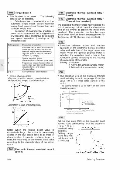
Electronic thermal overload relay 1(Level)
Electronic thermal overload relay 1(Thermal time constant)
The electronic thermal overload relay watches theoutput frequency, output current and operationtime of the inverter to prevent the motor fromoverheat. The protective function becomesactive when 150% of the set amperage flows forthe time set at F12 (thermal time constant).
• Selection between active and inactiveoperation of the electronic thermal overloadrelay and selection of the target motor aremade. When the general purpose motor isselected, the operation level is low at lowrevolution speeds according to the coolingcharacteristics of the motor.Setting: 0 Inactive
1 Active (for general purpose motor)2 Active (for forced-ventilated motor)
• The operation level of the electronic thermaloverload relay is set in amperage. Enter thevalue 1.0 to 1.1 times rated current of themotor.The setting range is 20 to 135% of the ratedinverter current.
F11
F10
F12
F11
Setting range Description of selection0 Automatic torque boost characteristics
where the torque boost value of theconstant torque load is automaticallyadjusted (refer to function code P04"Motor 1 ("(Tuning)").
1 Square reduction torquecharacteristics for fan and pump loads
2 Proportional torque characteristics forintermediate load between the squarereduction torque and torquecharacteristics.
3 to 31 Constant torque characteristics
Torque boost 1
• This function is for motor 1. The followingoptions can be selected.- Selection of load characteristics such asautomatic torque boost, square reductiontorque load, proportional torque load andconstant torque load.- Correction of magnetic flux shortage ofmotor in accordance with the voltage drop inlow frequency zone, and torque boost duringlow speed operation (boosting of V/fcharacteristics).
F09
• Torque characteristics<Square reduction torque characteristics><Proportional torque characteristics>
<Constant torque characteristics>
Note) When the torque boost value isexcessively large, the motor is excessivelyexcited in the low speed zone at all types ofcharacteristics. If operation continues in such astate, the motor may be overheated. Set a valueaccording to the characteristics of the drivenmotor.
Electronic thermal overload relay 1(Select)
F02
Set the time since 150% of the operation levelcurrent flows continuously until the electronict h e r m a loverload relayfunctions.Setting range:0.5 to 10.0 min. (minimum unit0.1 minute)
F12
When F10 = 1
When F10 = 2
10090
69
Fe x 0.33 Fe
Graph of relationship between operationlevel current and output frequency
Output Frequency Fo (Hz)
Ope
ratio
n Le
vel C
urre
nt [%
]
Fe = Fb (Fb = <50Hz)50Hz (Fb > 50Hz)
nb: Fb = Base Frequency

Selecting Functions 5-15
5
Electronic thermal overload relay(for External braking resistor)
• This function controls the operation frequencyof the braking resistor and the continuousoperation hours to prevent the brakingresistor from being overheated.Setting0: Inactive1: Active - (For details contact IMO)2:Active - (For details contact IMO)
Restart mode after momentary powerfailure
• Select the operation to be taken by theinverter upon momentary power failure.You can select between protective operation(alarm output, alarm display, and inverteroutput shutoff) upon detection of power failureto be taken against an undervoltage andrestart after momentary power failure wherethe coasting motor is not stopped butautomatically restarted after the sourcevoltage is recovered.Setting range: 0 to 3 (Refer to the table below
for details of the function.)
F14
F13 Function codes used for the restart aftermomentary power failure include H13 and H14.Refer to the description of these codes, too. Aswell, a rotating motor pickup function can beselected as a starting method after amomentary power failure. (Refer to functioncode H09 for details of setting.)When the pickup function is used, the speed ofthe coasting motor is detected and the motor isstarted without a shock. Because a speeddetection time is necessary if the pickupfunction is made effective, the pickup functionshould be made ineffective and restart shouldbe made at the frequency effective before thepower failure in a system with a large inertia torestore the original frequency, to make the mostof the small decrease in the speed of thecoasting motor.The effective range of the pickup function is 5 to120 Hz. If the detected speed is out of theeffective range, the inverter restarts accordingto the regular function of restart aftermomentary power failure.
Name of function Operation upon power failure Operation upon power recovery
0
1
2
3
Set
ting
Inactive aftermomentary powerfailure (The inverter tripsimmediately.)
Upon detection of anundervoltage, a protectivefunction is activated to stop theoutput.
The inverter doesnot restart.
The inverterrestarts afterthe protectivefunction isreset and anoperationcommand isinput.
Inactive after momentarypower failure (Theinverter trips after thepower is recovered.)
Upon detection of anundervoltage, no protectivefunction is activated but theoutput is stopped.
A protective functionis activated; theinverter does notrestart.
Restart after momentarypower failure (Theinverter restarts at thefrequency effective at thetime of power failure.)
Upon detection of anundervoltage, no protectivefunction is activated but theoutput is stopped.
The inverter automatically restarts atthe output frequency effective at thetime of power failure.
Restart after momentarypower failure (Theinverter restarts at thestarting frequency; forlow inertia loads.)
Upon detection of anundervoltage, no protectivefunction is activated but theoutput is stopped.
The inverter automatically restarts atthe starting frequency set at F23.
5-16 Selecting Functions
5
Note: The chain line indicates the motor speed.

Selecting Functions 5-17
5
Frequency limiter (High)
Frequency limiter (Low)
• Set the upper and lower limits of thefrequency setting.Setting range: 0 to 400 Hz
F16
F15 Bias frequency
This function obtains the frequency settingfrom addition of the frequency setting inrelation to the analog input and a biasfrequency. The operation is as shown in thefigure below.However, if the bias frequency is larger(smaller) than the maximum frequency (-maximum frequency), the limit is set at themaximum output frequency (- maximumoutput frequency).
F18
DC brake (Starting frequency)
DC brake (Braking level)
DC brake (Braking time)
• Starting frequency: Set the frequency atwhich the DC brake starts operation duringdeceleration and stop.Setting range: 0.0 to 60.0 Hz
• Braking level: Set the output current levelduring DC braking. The level can be set in anincrement of 1% of the rated inverter outputcurrent.Setting range: 0 to 100%Actual minimum level is fixed to 5% even ifthis function set from 1 to 5% forVXSM75-1/550-3.
• Braking time: Set the operation time of DCbraking.Setting range: 0.0 Inactive0.1 to 30.0 s
F22
F21
F20
F22
F21
F20
*The starting frequency is output when theinverter starts operation, and the stoppingfrequency is output when it stops operation.*(Low limit) > (High limit)...Priority is given to theHigh limit value.
Gain (Frequency setting signal)
• Set the ratio of the frequency setting inrelation to the analog input.The operation is as shown in the figure below.
F17
CAUTIONThe brake function of the inverterdoes not insure the function of a
mechanical latch. Injuries could occur.

5-18 Selecting Functions
5
Starting frequency (Frequency)
Starting frequency (Holding time)
Stop frequency
• The starting frequency can be set to insurethe torque during start of operation. Holdingtime for at the starting frequency beforeacceleration can be set to wait forestablishment of the magnetic flux of themotor during start of operation.
• Frequency: Set the starting frequency.Setting range: 0.1 to 60.0 Hz
• Holding time: Set the time for continuing thestarting frequency during start of operation.Setting range: 0.0 to 10.0 s
*The Holding time is not placed duringchangeover between forward and reverserotation.
*The Holding time is not included in theacceleration time.
*The function is effective even when C21 Timeroperation is selected; the time is included in thetimer value.
• Set the stop frequency.Setting range: 0.1 to 6.0 Hz
F25
F24
F23
F25
F24
F23
When the starting frequency is smaller than thestop frequency and the frequency setting issmaller than the stop frequency, operation doesnot start.
Motor sound (Carrier frequency)
• This function adjusts the carrier frequency.After adjustment, reduction of the motornoise, avoidance of resonance with themechanical system, reduction of leakagecurrent from the output circuit wiring,reduction of inverter noise and other effectscan be obtained.Setting range: 0.75 to 15 (0.75 to 15 kHz)
F25
Carrier frequency Lower HigherMotor noise Larger to SmallerOutput current waveform Worse to BetterLeakage current Less to MoreRF emissions Less to More
*A smaller setting causes a less sinusoidaloutput current waveform (with much harmoniccomponent) to cause an increase in the motorloss, resulting in a slightly higher motortemperature.
For example, when 0.75 kHz is set, reducethe motor torque by about 15%. When a largevalue is set, the inverter loss increases,raising the inverter temperature.
Motor sound (Sound tone)
• The sound tone of the motor noise can bechanged when the carrier frequency is 7 kHzor lower. Use the function according topreference.Setting range: 0, 1, 2, 3
FMA and FMP terminals (Select)
• Select the operation method of the FMterminal.0: Analog output (FMA function)1: Pulse output (FMP function)
FMA (Voltage adjust)
FMA (Function)
The output frequency, output current and othermonitor data can be output to the FM terminal ina DC voltage. The amplitude can be adjusted.Note) To use the FM terminal for analog outputs,set F29 at "0" and set SW1 on the control boardto FMA.
• Adjust the voltage corresponding to 100 [%]of the monitoring amount of the monitoringitem selected at F31 in a range from 0 to 200[%] (in an increment of 1 [%]).Setting range: 0 to 200 [%]
F30
F31
F30
F29
F27
F30:100%
F30:50%
F30:0%
50% 100%
10V or above10V
5V
FM
Ate
rmin
al o
utpu
tvo
ltage
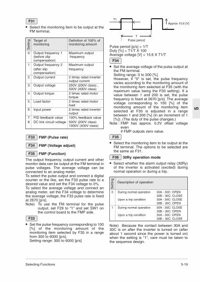
Selecting Functions 5-19
5
• Select the monitoring item to be output at theFM terminal.
F31
Target of Definition of 100% ofmonitoring monitoring amount
0 Output frequency 1 Maximum output(before slip frequencycompensation)
1 Output frequency 2 Maximum output (after slip frequencycompensation)
2 Output current 2 times rated inverteroutput current
3 Output voltage 250V (200V class) ,500V (400V class)
4 Output torque 2 times rated motortorque
5 Load factor 2 times rated motorload
6 Input power 2 times rated inverteroutput
7 PID feedback value 100% feedback value8 DC link circuit voltage 500V (200V class)
1000V (400V class)
Set
ting
FMP (Pulse rate)
FMP (Voltage adjust)
FMP (Function)
The output frequency, output current and othermonitor data can be output at the FM terminal inpulse voltages. The average voltage can beconnected to an analog meter.To select the pulse output and connect a digitalcounter or the like, set the F33 pulse rate to adesired value and set the F34 voltage to 0%.To select the average voltage and connect ananalog meter, set the F34 voltage to determinethe average voltage; the F33 pulse rate is fixedat 2670 [p/s].Note) To use the FM terminal for the pulse
output, set F29 to "1" and set SW1 onthe control board to the FMP side.
• Set the pulse frequency corresponding to 100[%] of the monitoring amount of themonitoring item selected by F35 in a rangefrom 300 to 6000 [p/s].Setting range: 300 to 6000 [p/s]
F33
F35
F34
F33
T1Approx 15.6 [V]
TPulse period
Pulse period [p/s] = 1/TDuty [%] = T1/T X 100 Average voltage [V] = 15.6 X T1/T
• Set the average voltage of the pulse output atthe FM terminal.Setting range: 0 to 200 [%]However, if "0" is set, the pulse frequencyvaries according to the monitoring amount ofthe monitoring item selected at F35 (with themaximum value being the F33 setting). If avalue between 1 and 200 is set, the pulsefrequency is fixed at 2670 [p/s]. The averagevoltage corresponding to 100 [%] of themonitoring amount of the monitoring itemselected at F35 is adjusted in a rangebetween 1 and 200 [%] (in an increment of 1[%]). (The duty of the pulse changes.)
Note : FMP has approx. 0.2V offset voltageevenif FMP outputs zero value.
• Select the monitoring item to be output at theFM terminal. The options to be selected arethe same as F31.
30Ry operation mode
• Select whether the alarm output relay (30Ry)of the inverter is activated (excited) duringnormal operation or during a trip.
F36
F35
F34
Description of operation
0 During normal operation 30A - 30C: OPEN30B - 30C: CLOSE
Upon a trip condition 30A - 30C: CLOSE30B - 30C: OPEN
1 During normal operation 30A - 30C: CLOSE30B - 30C: OPEN
Upon a trip condition 30A - 30C: OPEN30B - 30C: CLOSE
Set
ting
Note) Because the contact between 30A and30C is on after the inverter is turned on (afterabout 1 second since the power is turned on)when the setting is "1", care must be taken tothe sequence design.

5-20 Selecting Functions
5
Torque limiter 1 (Driving)
Torque limiter 1 (Braking)
• The torque limiting operation calculates themotor torque from the output voltage, current,resistance of the primary winding of the motorand other data to control the frequency sothat the calculated value does not exceed thecontrol value. This operation insures inverteroperation without tripping upon abruptchanges in the load torque while the limitvalue is maintained.
• Select the limit values of the driving torqueand braking torque.
• The acceleration/deceleration operation timeduring activation of this function becomeslonger than the set acceleration/decelerationtime. When the driving torque is limited duringconstant speed operation, the frequency islowered to reduce the load torque. (When thebraking torque is limited, the contrary occurs.)Setting range: 20 to 200,999%Set "999" to inactivate the torque limiter. Set only the braking torque to "0" toautomatically avoid OU tripping caused bypower regeneration.
F02
F40
WARNINGIf the torque limiter has beenselected, the inverter may operate at
an acceleration/deceleration time or speeddifferent from the set ones. Design themachine so that safety is ensured even insuch cases. Otherwise an accident could occur.
Torque vector control 1
• The torque vector control calculates thetorque suitable for the load to make the mostof the motor torque, and controls the voltageand current vectors to optimum onesaccording to the calculated value.
• When "1" (active) is selected, the settings ofthe following function codes become differentfrom the written ones.1) F09 "Torque boost 1"Works as "0" value (automatic torque boost).2) P09 "Slip compensation control"
F02
Slip compensation is automatically activated.When "0" is set, the slip compensationamount of a standard three-phase motor isassumed. When the setting is other than "0",the written setting is applied.
• Use the torque vector control function underthe following conditions.1) A single motorIf two or more motors are connected, vectorcontrol is not possible.2) The data of function codes of motor 1 (P03"Rated current", P06 "No-load current", P07"%R1" and P08 "%X") must be accurate UsePO4, Auto tuning.3) The rated motor current must not be muchsmaller than the rated inverter current.Though it depends on the model, the onesmaller by two ranks than the standardapplicable motor of the inverter is theallowable smallest motor.4) The wiring distance between the inverterand motor must be up to 50 m. Too long awiring distance disables accurate control dueto the leakage current flowing through thestatic capacitance between the cable and theground.5) When a reactor is connected between theinverter and the motor or when the wiringimpedance is too large to be overlooked,change the data using P04 "Auto tuning".If these conditions cannot be satisfied, leavethe setting at "0" (inactive).
Setting State of operation
– Inactive
– Active

Combination of input Selected frequencysignals
3 2 1 0[SS8] [SS4] [SS2] [SS1]
off off off off Selected by F01 or C30off off off on C05 Multistep frequency 1off off on off C06 Multistep frequency 2off off on on C07 Multistep frequency 3off on off off C08 Multistep frequency 4off on off on C09 Multistep frequency 5off on on off C10 Multistep frequency 6off on on on C11 Multistep frequency 7on off off off C12 Multistep frequency 8on off off on C13 Multistep frequency 9on off on off C14 Multistep frequency 10on off on on C15 Multistep frequency 11on on off off C16 Multistep frequency 12on on off on C17 Multistep frequency 13on on on off C18 Multistep frequency 14on on on on C19 Multistep frequency 15
Selecting Functions 5-21
5
E:Extension Terminal Functions
X1 terminal function
X2 terminal function
X3 terminal function
X4 terminal function
X5 terminal function
• The function of each digital input terminal X1to X5 can be set arbitrarily using a code.
E05
E04
E03
E02
E01
Setting Function0,1,2,3 Multistep frequency selection
(1 to 15 steps)4 Acceleration/deceleration selection
(1 step)5 Self holding selection [HLD]6 Coast-to-stop command [BX]7 Error reset [RST]8 External alarm [THR]9 Frequency setting 2 / frequency setting
1 [Hz2 / Hz1]10 Motor 2 / motor 1 [M2 / M1]11 DC brake command [DCBRK]12 Torque limit 2 / torque limit 1 [TL2 / TL1]13 UP command [UP]14 DOWN command [DOWN]15 Write enable for keypad (data change
allowed) [WE-KP]16 PID control cancel [Hz / PID]17 Forward/reverse operation switch
(terminal 12 and terminal C1) [IVS]18 Link operation selection
(RS485 standard, BUS Option) [LE]
Note) The data numbers not assigned to E01through E05 are considered to beinactive.
Multistep frequencyFrequencies set to function codes C05 throughC19 can be selected according to externaldigital input signal switching. Set data 0 to 3 tothe desired digital input terminals andcombination of input signals determines theselected frequency.
Multistep frequency selection
Acceleration/deceleration time selectionAcceleration/deceleration time set to functioncodes E10 and E11 can be selected accordingto external digital input signal switching.
3-wire operation stop command [HLD]Used for three-wire operation. When HLD-P24is ON, the FWD or REV signal is maintained,and when it is OFF, the signal is reset.
Note : The inverter operates while FWD-P24 orREV-P24 is ON even if HLD-P24 is OFF.An external interlock sequence ,whichmakes FWD-P24 and REV-P24 OFFwhen HLD-P24 is OFF, is required.
Input signal Selected 4[RT1] acceleration/deceleration time
off F07 Acceleration time 1F08 Deceleration time 1
on E10 Acceleration time 2E11 Deceleration time 2

5-22 Selecting Functions
5
Coast-to-stop command [BX]When the BX terminal is connected to the P24terminal, the inverter output is immediately shutoff and the motor coasts to stop. No alarm signalis output. This signal is not maintained.When the operation command (FWD or REV) isON and the BX terminal is disconnected fromthe P24 terminal, the motor starts at the startingfrequency.
Alarm reset [RST]Upon tripping, when the connection betweenthe RST and P24 terminals is turned on, thebatch alarm output is removed, and when theconnection is turned off, the trip display isremoved and operation is restarted.
Trip command (External fault) [THR]When the connection between the THR andP24 terminals is turned off, the inverter output isshut off (to allow the motor to coast to stop), andan alarm [OH2] is output. This signal ismaintained internally until an RST input isadded. This function is used to protect theexternal braking resistor from being overheated.When this terminal function is not set, an ONinput is assumed.
Frequency setting 2/1 [Hz2 / Hz1]An external digital input signal switches thefrequency setting method defined by functioncodes F01 and C30.The signal operation is changed under PIDcontrol. (Refer to H20 through H25.)
Input signal Selected 9[Hz2/Hz1] Frequency setting
off F01 Frequency setting 1on C30 Frequency setting 2
Input signal Selected motor10[M2/M1]
off Motor 1on Motor 2
Input signal Selected function15[WE-KP]]
off Data change disabledon Data change enabled
Motor 2/1 [M2 / M1]An external digital input signal switches eachmotor constant. However, this input is effectiveonly when the operation command to theinverter is turned off and the inverter is stopped.Therefore operation at 0 Hz is not included.
DC brake command [DCBRK]When the external digital input signal is ON, DCbraking starts and continues as far as the signalremains turned on after the operation commandis turned off (or, the STOP key is pressed in thekeypad panel operation mode or both the FWDand REV terminals are turned on or turned off inthe terminal block operation mode) and theinverter frequency drops below the frequencyset at F20. In this case, the longer time betweenthe time set at function code F22 and the timewhen the input signal is turned on, is givenpriority.However, operation is restarted if the operationcommand is turned on.Torque limiter 2/Torque limiter 1 [TL2 / TL1]An external digital input signal switchesbetween the torque limiter values set at functioncodes F40 and F41 or E16 and E17.
Input signal Selected torque limit value 12[TL2/TL1]
off F40 Torque limiter 1 (Driving)F41 Torque limiter 1 (Braking)
on E16 Torque limiter 2 (Driving)E17 Torque limiter 2 (Braking)
Input signal Selected function 13 14 (when operation command is ON)off off The output frequency is maintained.off on The output frequency increases at the
acceleration time.on off The output frequency decreases at the
deceleration time.on on The output frequency is maintained.
UP command [UP] / DOWN command [DOWN]The output frequency can be increased ordecreased according to the external digital inputsignal while the operation command is input(turned on). The changing range is 0 to themaximum output frequency and operation in adirection opposite to that in the operationcommand is impossible.
Write enable for KEYPAD [WE-KP]This function allows program changes onlywhile the external signal is input; this is for theprotection of the program from inadvertentchanges.
Note) If data 15 is set to a terminalerroneously, program change becomedisabled. Turn the terminal ON thenchange to another number.

Selecting Functions 5-23
5
Input signal Selected function18[LE]
off Link command invalidon Link command valid
Input signal Selected function 16[Hz/PID]
off PID control validon PID control invalid
(frequency setting through keypad panel)
Input signal Selected function17[IVS]
off When forward operation is setforward operationWhen reverse operation is setreverse operation
on When forward operation is setreverse operationWhen reverse operation is setforward operation
Inverter running [RUN]"Inverter running" means that the inverteroutputs a frequency as a speed signal. At thistime, an ON signal is output. However, if the DCbraking function is active, the signal is turnedoff.
Frequency equivalence [FAR]Refer to the description for function code E30Frequency equivalence (detection width).
Frequency level detection [FDT]Refer to the description for function codes E31and E32 Frequency level detection.
Undervoltage detection signal [LV]When the undervoltage protection function isactive, that is, when the main circuit DC voltageis below the undervoltage detection level, anON signal is output. After the voltage is restoredto become higher than the undervoltagedetection level, the signal is turned off. The ONsignal is output also during activation of theundervoltage protection function.Undervoltage detection level: Approx 200 Vdc (200V class)Approx 400Vdc (400V class)
PID control cancel [Hz/PID]An external digital input signal can disable PIDcontrol.
Inverse mode changeover (Terminal 12 andC1) [IVS]An external digital input signal switchesbetween the forward and reverse operations ofanalog inputs (terminals 12 and C1).
Link enable (RS485) [LE]An external digital input signal is switched tovalidate or invalidate the frequency commandand operation command from the link. Thesource of the command can be set at H30 Linkfunction.
Acceleration time 2
Deceleration time 2
• Additional acceleration and deceleration timecan be selected besides F07 "Accelerationtime 1" and F08 "Deceleration time 1".
• The operation and setting range are the sameas those for F07 "Acceleration time 1" andF08 "Deceleration time 1". Refer to thesefunctions.
• To switch between the acceleration anddeceleration time, select any terminal fromamong E01 "X1 terminal (Function selection)"through E05 "X5 terminal (Function selection)"as a switching signal input terminal. Set theselected terminal to "4"(acceleration/deceleration time selection) andsupply a signal to the terminal to switch.Switching is effective during acceleration,during deceleration or during constant speedoperation.
E11
E10
Torque limiter 2 (Driving)
Torque limiter 2 (Braking)
• Use these functions to switch the torquelimiter levels set at F40 and F41 using anexternal control signal. The external signal issupplied to an arbitrary control terminalamong X1 through X5, the function of whichis set to torque control 2 / torque control 1(data 12) at E01 to E05.
Y1 terminal function
Y2 terminal function
• A part of control and monitor signals can beoutput at the Y1 and Y2 terminals.
E21
E20
E17
E16
Setting Output signal0 Inverter running [RUN]1 Frequency equivalence [FAR]2 Frequency level detection [FDT]3 Undervoltage detection signal [LV]4 Torque polarity [B/D]5 Torque limiting [TL]6 Auto restarting [IPF]7 Overload early warning [OL]8 Life time alarm [LIFE]9 Frequency level detection 2 [FAR2]

5-24 Selecting Functions
5
FDT function signal (Level)
FDT function signal (Hysteresis)
• Determine the operation (detection) level ofthe output frequency and the hysteresis widthfor operation cancellation. When the outputfrequency exceeds the set operation level, anON signal can be output from the terminal.Setting range: (Operation level): 0 to 400 Hz
(Hysteresis width): 0.0 to 30.0 Hz
E32
E31
Torque polarity [B/D]The polarity of the torque calculated inside theinverter is judged and the driving/braking torquediscrimination signal is output.When the calculated torque is positive/driving,an OFF signal is output, and when it isnegative/braking, an ON signal is output.
Torque limiting [TL]When the torque limit is set, a stall preventionfunction automatically functions to change theoutput frequency automatically; the torquelimiting signal is output externally to reduce theload or to indicate an excessive load at themonitor.The ON signal is output during torque limit,regeneration avoidance operation and currentlimit.
Auto restarting [IPF]An event of momentary power failure, start-up ofrestart mode after momentary power failure,and automatic synchronization and recovery arereported to the outside.When the power is recovered andsynchronization starts after a momentary powerfailure, an ON signal is output, and the signalchanges to the OFF signal after the frequencybefore the momentary power failure is achieved.In the startup at the starting frequency mode,completion of restart is assumed at the time ofpower recovery, and the signal is turned off inthis timing. (Refer to the description for F14.)
Overload early warning [OL]An overload early warning level before thermalprotection trip (electronic thermal overloadrelay) of the motor is judged and an ON signal isoutput.Either the electronic thermal overload forecastor output current overload forecast can beselected for overload forecast judgement.For the setting method, refer to Overload earlywarning (Operation selection) (E33) andOverload early warning (Operation level) (E34).Note) This function is effective only for motor 1.
Life time alarm [LIFE]Life judgement output for main circuit capacitorRefer to section 8-2 (1) "Capacity measurementof main circuit capacitor" for description.
Frequency level detection 2 [FAR2]This is a frequency level detection (detectionwidth) signal where function code E29"Frequency level detection delay" takes effect.Detection level of the frequency is detected atthe output frequency before the torque limiter.
Frequency level detection delay
FAR function signal (Hysteresis)
• Adjust the hysteresis and signal output delayfor achievement of the output frequency tothe set frequency (operation frequency).The delay is valid only for FAR2 and it can beadjusted between 0.01 and 10.0 seconds.The hysteresis can be adjusted in a range of0 to +/-10 Hz of the output frequency.The output frequency changes according to thetorque limiting operation. When the frequencyexceeds the setting range (width), the signalis turned off in a mode (FAR: E20, 21 set to"1") or it is not turned off in another mode(FAR2: E20, 21 set to "9").E29: Setting range: 0.01 to 10.0 sE30: Setting range: 0.0 to 10.0 HzAn ON signal can be output from the terminalwithin the detection range (width).
E30
E29
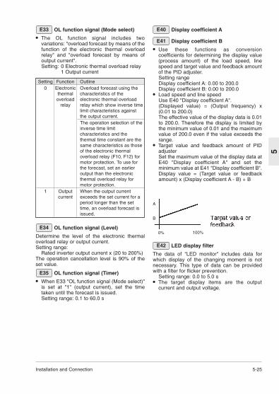
Installation and Connection 5-25
5
OL function signal (Mode select)
• The OL function signal includes twovariations: "overload forecast by means of thefunction of the electronic thermal overloadrelay" and "overload forecast by means ofoutput current".Setting: 0 Electronic thermal overload relay
1 Output current
E33
Setting Function Outline0 Electronic Overload forecast using the
thermal characteristics of the overload electronic thermal overload
relay relay which show inverse timelimit characteristics againstthe output current.The operation selection of theinverse time limitcharacteristics and thethermal time constant are thesame characteristics as thoseof the electronic thermaloverload relay (F10, F12) formotor protection. To use forthe forecast, set an earlieroutput than the electronicthermal overload relay formotor protection.
1 Output When the output current current exceeds the set current for a
period longer than the settime, an overload forecast isissued.
OL function signal (Level)
Determine the level of the electronic thermaloverload relay or output current.Setting range:
Rated inverter output current x (20 to 200%)The operation cancellation level is 90% of theset value.
OL function signal (Timer)
• When E33 "OL function signal (Mode select)"is set at "1" (output current), set the timetaken until the forecast is issued.Setting range: 0.1 to 60.0 s
E35
E34
Display coefficient A
Display coefficient B
• Use these functions as conversioncoefficients for determining the display value(process amount) of the load speed, linespeed and target value and feedback amountof the PID adjuster.Setting rangeDisplay coefficient A: 0.00 to 200.0Display coefficient B: 0.00 to 200.0
• Load speed and line speedUse E40 "Display coefficient A".(Displayed value) = (Output frequency) x(0.01 to 200.0)The effective value of the display data is 0.01to 200.0. Therefore the display is limited bythe minimum value of 0.01 and the maximumvalue of 200.0 even if the value exceeds therange.
• Target value and feedback amount of PIDadjusterSet the maximum value of the display data atE40 "Display coefficient A" and set theminimum value at E41 "Display coefficient B".Display value = (Target value or feedbackamount) x (Display coefficient A - B) + B
E41
E40
LED display filter
The data of "LED monitor" includes data forwhich display of the changing moment is notnecessary. This type of data can be providedwith a filter for flicker prevention.
Setting range: 0.0 to 5.0 s• The target display items are the output
current and output voltage.
E42
A
B
0% 100%

5-26 Selecting Functions
5
C: Control Functions of Frequency
C01 Jump frequency 1
C02 Jump frequency 2
C03 Jump frequency 3
C04 Jump frequency hysteresis
• These functions jump the inverter outputfrequency at the set frequencies to avoidmechanical resonance with the load.
• Three jump frequencies can be set.• This function is inactive when all the jump
frequencies 1 through 3 are set at 0 Hz.• The frequencies are not jumped during
acceleration or deceleration.If the setting ranges of jump frequenciesoverlap, the sum of the setting ranges isjumped.
Setting range: 0 to 400 HzMinimum unit: 1 Hz
Setting range: 0 to 30 HzMinimum unit: 1 Hz
C04
C03C02C01
C04
C03
C02
C01
Multistep frequency 1 through
Multistep frequency 15
• Terminal functions SS1, SS2, SS4 and SS8are turned on or off to switch multistepfrequencies 1 through 15. (Refer to E01through E05 for the definition of the terminalfunction.)
• Undefined terminals among terminalfunctions SS1, SS2, SS4 and SS8 areassumed to be turned off.Setting range: 0.00 to 400.0 HzMinimum unit: 0.01 Hz
C19
C05

Selecting Functions 5-27
5
Timer operation
Stage 1
• An operation pattern from the start ofoperation to automatic stop can be created.
• Select active or inactive timer operation.0: Inactive timer operation1: Active timer operation
• Set the time from the start of operation toautomatic stop.Setting range: 0.00 to 3600 s
Note) If the power is turned off or the inverter isstopped or trips during timer operation,the counted time is reset.
Frequency command 2
• Select the frequency setting method.For the selectable frequency setting methods,refer to the description of F01.
Analog setting signal offsetadjustment (Terminal 12)
Analog setting signal offsetadjustment (Terminal C1)
• Set the offset of the analog input (terminal[12], terminal [C1]).The offset can be set in the range between -5.0 [%] and + 5.0 [%] of the maximum outputfrequency (in 0.1 [%] step).
C32
C31
C30
C22
C21
C22
C21
Analog setting signal filter
• The analog signal supplied to control terminal12 or C1 sometimes includes electric noise.Electric noise make the control unstable.Adjust the time constant of the input filter toremove the effects of electric noise.Setting range: 0.00 to 5.00 s
• With a large time constant (setting), thecontrol becomes stable but there is a delay inthe control response. With a small timeconstant, the response is quick but thecontrol becomes unstable.If the setting is not clear, change the settingwhen the control is unstable or the responseis slow.
Note) The function applies to both terminals[12] and [C1] (in common). However,when a PID feedback signal is input,H25 "PID control feedback filter" isapplied.
C33

5-28 Selecting Functions
5
P: Motor parameters
Number of motor 1 poles
• This parameter is the number of poles ofdriven motor 1. Write a value to displaycorrect motor speeds (synchronized speeds)at the LED.Setting range: 2, 4, 6, 8, 10, 12 or 14
Motor 1 (Capacity)
• A standard applicable motor capacity is setbefore shipment from the factory. Change thesetting to drive a motor rated at other than thestandard applicable motor capacity.Setting range:0.01 to 5.50 kW(3.7kW orsmaller)0.01 to 11.00kW (5.5,7.5kW)Set the standard applicable motor capacityspecified in section 9-1 "StandardSpecifications". The setting range should bebetween one size higher or lower by twosizes from the standard applicable motorcapacity. If the range is exceeded, accuratecontrol may not be possible. If a valuebetween the standard applicable motorcapacity and the capacity of another size isset, the data of the lower capacity isautomatically written for the data of therelated functions.
• After the setting of this function is changed,the settings of the following related functionschange to the data for standard three-phasemotor.P03 "Motor 1 (Rated current)"P06 "Motor 1 (No-load current)"P07 "Motor 1 (%R1)"P08 "Motor 1 (%X)"
Note) The settings of three-phase standardmotor are the data for 3-phase 200V or400V/ 50 Hz.
Motor 1 (Rated current)
• This parameter is the rated current of motor1.Setting range: 0.00 to 99.9 A
Motor 1 (Tuning)
• The motor data is measured and the data isautomatically written.
P04
P03
P01
P01
Setting State of operation0 Inactive1 The primary resistance (%R1) of the
motor and the leakage reactance (%X) at the base frequency are measured while the motor is stopped, and the datais automatically written to P07 and P08.(Static tuning)
2 The primary resistance (%R1) of the motor and the leakage reactance (%X) at the base frequency are measured while the motor is stopped, then the no-load current (Io) is measured while the motor turns, and P06, P07 and P08 are automatically written.(Dynamic tuning)
• Perform a tuning when the P06, P07 and P08data written in the inverter in advance differsfrom the actual motor data, that is, in thefollowing cases. Improvement in the controland calculation accuracy is expected.- When a motor other than non standard
three-phase motor (4 poles) is used.- When the impedance on the output side
cannot be ignored due to a long wiringlength between the inverter and the motoror connection of a reactor.
- When %R1 or %X is unknown due to anonstandard motor or a special motor.
Tuning procedure
1. Adjust the voltage and frequency according tothe characteristics of the motor. Adjust "F03","F04", "F05" and "F06".
2. Enter the motor constants which cannot betuned. P02 "Capacity", P03 "Rated current",P06 "No-load current" (The no-load current isnot necessary in Dynamic tuning.)
3. To tune the no-load current, too, disconnectthe motor from the mechanical units andcheck that no danger occurs even if the motorturns.
4. Set P04 "Tuning" to "1" (motor stop) or "2"(motor rotation) and press the FUNC/DATAkey to write the data, then issue an operationcommand (press the RUN key or turn theFWD or REV terminal on) to start tuning.Tuning takes several seconds to several tensof seconds. (When the setting is "2", themotor accelerates to a half of the basefrequency in the set acceleration/decelerationtime to tune the no-load current, thendecelerates. Therefore the time necessary fortuning varies according to the setacceleration/deceleration time.)
5. During tuning, the set data ("1" or "2") blinksrapidly and, upon the end of tuning, the next
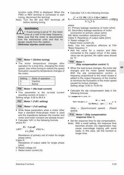
Selecting Functions 5-29
5
function code (P05) is displayed. When theFWD or REV terminal is connected to starttuning, disconnect the terminal.
Note) Turn the BX and RST terminals offbefore starting tuning.
WARNING• If auto tuning is set at "2", the motorturns at a half of the base frequency.
Make sure that the motor is disconnectedfrom the mechanical units and that nodanger results from the rotation. Otherwise injuries could occur.
Motor 1 (Online tuning)
• The motor temperature changes afteroperation for a long time, changing the motorspeed. Use online tuning to reduce the speedfluctuation caused by temperature changes ofthe motor.
P05
Setting State of operation0 Inactive1 Active
Motor 1 (No-load current)
• This parameter is the no-load current(exciting current) of motor 1.
Setting range: 0.00 to 99.9 A
Motor 1 (%R1 setting)
Motor 1 (%X setting)
• Write these parameters when a motor otherthan a standard three-phase motor is usedand the impedance between the inverter andmotor and motor constant are already known.
• Calculate %R1 in the following formula.where R1:
Resistance of primary coil of motor for singlephase [ohm]
Cable R: Resistance of output cable for single phase[ohm]
V: Rated voltage [V]I: Rated motor current [A]
P08
P07
P06
• Calculate %X in the following formula.
where X1: Primary leakage reactance of motor [ohm]X2: Secondary leakage reactance of motor
(conversion to primary value) [ohm]XM: Motor excitation reactance [ohm]Cable X: Reactance of output cable [ohm]V: Rated voltage [V]I: Rated motor current [A]Note) Use the reactance effective at F04"Base frequency 1".• Add the value for a reactor and filter
connected to the output circuit. If the cablevalue can be ignored, the cable value shouldbe "0".
Motor 1 (Slip compensation control 1)
• When the load torque changes, the motor slipchanges and the motor speed fluctuates.With the slip compensation control, afrequency proportional to the motor torque isadded to the output frequency of the inverterto minimize the fluctuation of the motor speedcaused by torque changes.Setting range: 0.00 to 15.00 Hz
• Calculate the slip compensation data in thefollowing formula.
(Slip) = (Synchronized speed) - (Ratedspeed)
Motor 1 (Slip compensationresponse time 1)
• Set the response time for slip compensation.Note) With a small setting, the response time
becomes shorter, but regeneration maycause overvoltage tripping with someloads. In this case, set this function tolonger time.
P10
P09
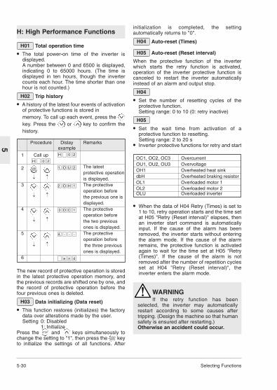
5-30 Selecting Functions
5
OC1, OC2, OC3 OvercurrentOU1, OU2, OU3 OvervoltageOH1 Overheated heat sinkdbH Overheated braking resistorOL1 Overloaded motor 1OL2 Overloaded motor 2OLU Overloaded inverter
H: High Performance Functions
Total operation time
• The total power-on time of the inverter isdisplayed.A number between 0 and 6500 is displayed,indicating 0 to 65000 hours. (The time isdisplayed in ten hours, though the invertercounts each hour. The time shorter than onehour is not counted.)
Trip history
• A history of the latest four events of activationof protective functions is stored inmemory. To call up each event, press the Ikey. Press the or key to confirm thehistory.
H02
H01
Procedure Dislay Remarksexample
1 Call up
2 The latestprotective operationis displayed.
3 The protective operation before the previous one is displayed.
4 The protective operation before the two previous ones is displayed.
5 The protective operation before the three previous ones is displayed.
6 dne
---4.
1CO3
1HO2.
2UO1.
20H
20H
FUNCDATA
V
V
V
V
V
V
V
V
V
V
The new record of protective operation is storedin the latest protective operation memory, andthe previous records are shifted one by one, andthe record of protective operation before thefour previous ones is deleted.
Data initializing (Data reset)
• This function restores (initializes) the factorydata over alterations made by the user.Setting 0: Disabled
1: InitializePress the and keys simultaneously tochange the setting to "1", then press the keyto initialize the settings of all functions. After
H03
initialization is completed, the settingautomatically returns to "0".
Auto-reset (Times)
Auto-reset (Reset interval)
When the protective function of the inverterwhich starts the retry function is activated,operation of the inverter protective function iscanceled to restart the inverter automaticallyinstead of an alarm and output stop.
• Set the number of resetting cycles of theprotective function.Setting range: 0 to 10 (0: retry inactive)
• Set the wait time from activation of aprotective function to resetting.Setting range: 2 to 20 s
• Inverter protective functions for retry and start
H05
H04
H05
H04
STOP
V
FUNCDATA
• When the data of H04 Retry (Times) is set to1 to 10, retry operation starts and the time setat H05 "Retry (Reset interval)" elapses, thenan inverter start command is automaticallyinput. If the cause of the alarm has beenremoved, the inverter starts without enteringthe alarm mode. If the cause of the alarmremains, the protective function is activatedagain to wait for the time set at H05 "Retry(Times)". If the cause of the alarm is notremoved after the number of repetition cyclesset at H04 "Retry (Reset interval)", theinverter enters the alarm mode.
WARNINGIf the retry function has been
selected, the inverter may automaticallyrestart according to some causes aftertripping. (Design the machine so that humansafety is ensured after restarting.)Otherwise an accident could occur.
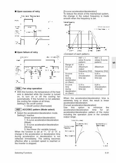
Selecting Functions 5-31
5
Upon success of retry
Upon failure of retry
Fan stop operation
• With this function, the temperature of the heatsink is detected while the inverter is turnedon, to turn on or off the cooling fanautomatically. If this function is not selected,the cooling fan rotates at all times.Setting 0: No on/off control
1: On/off control (thermostat)
ACC/DEC pattern (Mode select)
• Select the acceleration/deceleration mode.Setting 0: Inactive
(linear acceleration/deceleration)1: S-curve acceleration/deceleration (Weak)2: S-curve acceleration/deceleration (Strong)3: Non-linear (for variable torque)
When the function is set at "1", "2" or "3", achange in the acceleration or deceleration timeduring acceleration or deceleration is notreflected immediately. The setting becomeseffective after a constant speed is reached orthe inverter is stopped.
H07
H06
[S-curve acceleration/deceleration]To reduce the shock of the mechanical system,the change in the output frequency is madesmooth when the frequency is set.
<Constant of each pattern>
When the acceleration/deceleration time isextremely long or short, the result is linearacceleration/deceleration.[Curved acceleration/deceleration]Use this option to minimize theacceleration/deceleration time for anacceleration/deceleration pattern of the motorincluding the operation zone in the constantoutput range.
H07 = 1 H07 = 2(slow S-curve (steep S-curve pattern) pattern)
Range of 0.05 x S-curve (Maximum (Maximum(α) output
frequency [Hz]) frequency [Hz])S-curve 0.10 x 0.20 xtime (Acceleration (Accelerationduring time [s]) time [s])accelerationon (ßacc)S curve 0.10 x 0.20 x time (Deceleration (Decelerationduring time [s]) time [s])decelerationon (ßacc)
α
α
β β β β

5-32 Selecting Functions
5
Start mode (Rotating motor pickup)
• This function smoothly starts a motorcoasting due to an external force or the likeafter momentary power failure.The speed of the motor is detected uponpower recovery or restart and the samefrequency as that for the motor speed isoutput. Therefore the motor starts smoothlywithout a shock. However, when the coastingspeed of the motor converted in the inverterfrequency exceeds 120 Hz, setting of F03"Maximum frequency 1" or setting of F15"Frequency limiter (High)", the regularstarting method is adopted.
H09
Setting Regular starting Restarting after momentary power failure
0 Inactive Inactive1 Inactive Active2 Active Active
• Description of setting1: This function is effective when the setting of
F14 "Restart after momentary power failure(Operation selection)" is "2" or "3".Starting is made at the same frequency asthat for the coasting speed.
2: Upon restart after momentary power failure,operation command ON and other startingmethods, the speed of the coasting motor isdetected and starting is made at the samefrequency as that for the coasting speed.
Note) When this function is used, use thefollowing setting to detect the accuraterotation speed of the motor.
When a non-standard motor is used or whenthe wiring length is long, perform P04 Tuning.
Energy-saving operation
• When the output frequency for a small load isconstant (constant speed operation) and thesetting of F09 "Torque boost 1" is other than"0", the output voltage is automaticallylowered to minimize the product (power) ofthe voltage and the current.Setting 0: Inactive
1: ActiveNotes)1. Use this function for fans, pumps or other
square reduction torque loads. If this functionis applied to a constant torque load or to anapplication with a rapidly changing load, thereis a delay in the control response.
2. The energy-saving operation is automaticallycanceled to resume regular operation duringacceleration or deceleration or when the torquelimiter function is activated.
H10
Dec mode
• Select the stopping method of the inverterafter a stop command.Setting 0: Normal
(Deceleration to stop based on data of H07 "ACC/DEC pattern")1: Coast-to-stop
Note) This function is not activated when theset frequency is lowered to stop. Thefunction is activated only when a stopcommand is input.
Instantaneous overcurrent limiting
• When the motor load abruptly changes tocause a current exceeding the protectivelevel of the inverter to flow, the inverter tripsdue to the overcurrent. The Instantaneousovercurrent limiting function controls theinverter output within the protective level evenupon an excessive load.
• The operation level of the Instantaneousovercurrent limiting cannot be adjusted. Usethe torque limit function to set on outputlimitation.
• The torque generated by the motor maybecome low in a Instantaneous overcurrentlimiting state. Therefore deactivate themomentary overcurrent limit function forapplications such as the elevator where thetorque generated by the motor must not below. In this case, because the inverter tripsdue to an overcurrent when a currentexceeding the protective level of the inverterflows, use forcible stopping measures by amechanical brake or other protectivemeasures.Setting 0: Inactive
1: Active
Auto-restart (Restart time)
• When the power supply to a running motor isshut off or power failure occurs and the powersupply is quickly switched to another system,the phase of the voltage of the new systemdeviates from the phase of the voltageremaining in the motor and electrical ormechanical trouble may be developed. Whenswitching the power supply system in a shorttime, write the time for attenuation of theremaining voltage from the motor after powershutoff. The setting is effective during restartafter momentary power failure.Setting range: 0.1 to 5.0 s
If the duration of momentary power failure isshorter than the wait time data, restart is madeafter this time. If the duration of momentarypower failure is longer than the wait time data,
H13
H12
H11

Selecting Functions 5-33
5
restart is made after completion of operationpreparation of the inverter (about 0.2 to 0.5 s).
Auto-restart(Frequency fall rate)
• This function determines the drop ratio of theoutput frequency for the synchronizationbetween the output frequency of the inverterand the motor speed, that is, the speed ofsynchronization. This function is also used todrop the frequency as a stall preventionfunction for an excessive load during regularoperation.Setting range: 0.00, 0.01 to 100.0 Hz/sSet "0.00" to drop according to the currentlyselected deceleration time.
Note) A large frequency drop ratio may causetemporary increase in the regenerationenergy from the load, activating theovervoltage protection function. On thecontrary, a small frequency drop ratiomay cause long operation time of thecurrent limit function, activating theinverter overload protection function.
PID control (Mode select)
to
PID control (Feedback filter)
• The PID control detects a control amount(feedback value) from the sensor of thecontrolled object and compares it with thereference value (set temperature, etc.). Upondifference between them, an action is takento reduce the difference. That is, this controlmethod makes the feedback value becomeconsistent with the reference value. Thismethod can be applied to flow control,pressure control, temperature control andother process controls.
H25
H20
H14
• Because forward and reverse operation canbe selected for the output of the PIDcontroller, the rpm of the motor can beincreased or decreased in relation to theoutput of the PID controller.
Setting 0: Inactive1: Normal operation2: Inverse operation
H20
• The reference value can be given at F01"Frequency command 1" or directly input fromthe keypad panel.Select an arbitrary terminal from E01 "X1terminal (Function selection)" through E05"X5 (Function selection), and set data "9"(frequency command 2 / frequency command1).To obtain the reference value from F01"Frequency command 1", input an OFF signalto the selected terminal. When inputtingdirectly from the keypad panel, turn theselected terminal on.
• The process amount of the reference valueand feedback value can be displayed basedon the setting at E40 "Display coefficient A"and E41 "Display coefficient B".
Display coefficient A
Display coefficient B
0 100%
100% reference valuefeedback value

5-34 Selecting Functions
5
PID control (Feedback signal)
• Select the feedback value input terminal andelectrical specification of the terminal. Selectone from the table below according to thespecifications of the sensor.
H21
Setting Selection item0 Control terminal 12, normal
operation (voltage input 0 to +10V)1 Control terminal C1, normal
operation (current input 4 to 20 mA)2 Control terminal 12, inverse
operation (voltage input +10 to 0V)3 Control terminal C1, inverse
operation (current input 20 to 4 mA)
PID control (P (P gain))
• Generally speaking, P: gain, I: integral timeand D: differential time are not used alone.Functions are combined like: P control, PIcontrol, PD control and PID control.
• P actionAn operation where there is proportionalrelationship between the amount of operation(output frequency) and deviation is called Poperation. Therefore the P action outputs anoperation amount proportional to thedeviation. However, the deviation cannot beeliminated by only the P action.Setting range: 0.01 to 10.00 times
H22
Note) The feedback value of the PID controlcan be input only in the positive polarity.The negative polarity (0 to -10 Vdc, -10to 0 Vdc, etc.) cannot be input. Thereforethe control cannot be applied toreversible operation using the analogsignal.
• The P gain is a parameter which determinesthe degree of response to the deviation of Paction. With a large gain, the response isquick but hunting is likely to occur. With asmall gain, the response is stable but slow.

Selecting Functions 5-35
5
PID control (I (integral time))
• I actionAn operation where the speed of the changein the amount of operation is proportional tothe deviation is called I action. Therefore theI action outputs an operation amountobtained from integration of the deviation. Forthis reason, the I action is effective toconverge the control amount to the referencevalue. However, response is slow to thedeviation with abrupt changes.
H23
Setting range: 0.0 Inactive, 0.1 to 3600 sTo determine the effect of the I action, I: integral time is used as a parameter. With along integral time, the response is slow andreaction to an external force is small. With asmall integral time, the response is quick.When the integral time is too small, there ishunting.
PID control (D (Differential time))
• D actionAn operation where the amount of operation
is proportional to the differential value of thedeviation is called D action. Therefore, the Daction outputs an operation amount obtainedfrom the differentiation of the deviation and theresponse to abrupt changes is quick.
H24
time, vibration may become larger. With asmall differential time, decrease in thedeviation becomes smaller.
• PI controlDeviation remains with P action only. Toeliminate the remaining deviation, I action isadded and P + I control is generally adopted.The PI control functions to always eliminatedeviation in spite of changes in the referencevalue and stationary disturbances. However,when the I action is strong, response to thedeviation with abrupt changes is slow.P action only can be used for loads with an
integral factor.
• PD controlUpon deviation, the PD control generates anoperation amount larger than that obtained byD action only, to reduce the increase of thedeviation. When deviation is reduced tosmall, the function of the P action is madesmaller.For a load including integral factors to becontrolled, the P action alone can causehunting in the response due to the action ofthe integral factors. The PD control is used insuch cases to decrease hunting of the Paction to stabilize. That is, this control methodis applied to loads having no braking in theprocess itself.
• PID controlThe function of the I action to reduce thedeviation and the function of the D action tosuppress hunting are combined with the Paction. Accurate responses without deviationare obtained.This control method is effective to loadswhich take time from generation of deviationto development of a response.
PID control (Feedback filter)
• This function provides a filter for the feedbacksignal input at control terminal 12 or C1. Thefilter makes the operation of the PID controlsystem stable. However, an excessively largesetting causes a poor response.Setting range: 0.0 to 60.0 s
H25
Setting range: 0.00 Inactive, 0.01 to 10.0 sD: differential time is used as a parameter todetermine the effect of the D action. With along differential time, decrease in thevibration caused by the P action upondeviation is quick. With too large a differential

5-36 Selecting Functions
5
PTC thermistor (Mode select)
• Select this function for a motor equipped witha PTC thermistor for overheat protection.Setting0: Inactive1: ActiveConnect the PTC thermistor as shown in thefigure. The protective operation is commonwith the external alarm input. Therefore theprotective function operates at the "externalalarm".
H26
PTC thermistor (Level)
• The voltage input at terminal [C1] iscompared with the set voltage and, when theinput voltage at terminal [C1] is larger thanthe set voltage (operation level), H26 "PTCthermistor (Operation selection)" is activated.Setting range: 0.00 to 5.00 V(The setting smaller than 0.10 is handled as0.10.)
• The alarm temperature is determined by thePTC thermistor and the internal resistance ofthe PTC thermistor changes largely at thealarm temperature. Set the operation(voltage) level using this change ofresistance.
H27
From the figure of H26 "PTC thermistor(Operation selection)", the 250-ohm resistor andthe PTC thermistor (resistance Rp) configure aparallel circuit. Therefore voltage VC1
(operation level) of terminal [C1] is calculated inthe following equation.
The operation level can be set when RP of theVC1 calculation equation is in the followingrange.RP1 < RP < RP2To determine RP simply, calculate the followingequation.
Droop operation
• To drive one machine with two or moremotors, a larger load is exerted on the motorwith a larger speed. The droop controlattributes drooping characteristics to thespeed during load fluctuation to balance theload.
• The drooping amount is calculated in thefollowing formula.
H28
Setting range: - 9.9 Hz to 0.0 Hz
Serial link (Function select)
• RS485 (standard accessory) can beconnected as a link function (communicationfunction).
• As a link function, the following items arepossible.
H30
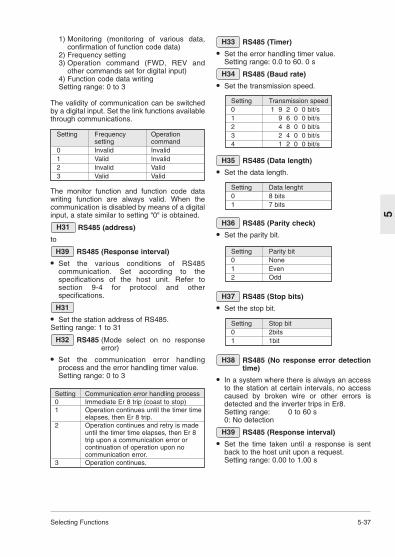
Selecting Functions 5-37
5
1) Monitoring (monitoring of various data,confirmation of function code data)
2) Frequency setting3) Operation command (FWD, REV and
other commands set for digital input)4) Function code data writingSetting range: 0 to 3
Setting Frequency Operation setting command
0 Invalid Invalid1 Valid Invalid2 Invalid Valid3 Valid Valid
The validity of communication can be switchedby a digital input. Set the link functions availablethrough communications.
The monitor function and function code datawriting function are always valid. When thecommunication is disabled by means of a digitalinput, a state similar to setting "0" is obtained.
RS485 (address)
to
RS485 (Response interval)
• Set the various conditions of RS485communication. Set according to thespecifications of the host unit. Refer tosection 9-4 for protocol and otherspecifications.
• Set the station address of RS485.Setting range: 1 to 31
RS485 (Mode select on no responseerror)
• Set the communication error handlingprocess and the error handling timer value.Setting range: 0 to 3
H32
H31
H39
H31
Setting Communication error handling process0 Immediate Er 8 trip (coast to stop)1 Operation continues until the timer time
elapses, then Er 8 trip.2 Operation continues and retry is made
until the timer time elapses, then Er 8 trip upon a communication error or continuation of operation upon no communication error.
3 Operation continues.
RS485 (Timer)
• Set the error handling timer value.Setting range: 0.0 to 60. 0 s
RS485 (Baud rate)
• Set the transmission speed.
H34
H33
Setting Transmission speed0 1 9 2 0 0 bit/s1 9 6 0 0 bit/s2 4 8 0 0 bit/s3 2 4 0 0 bit/s4 1 2 0 0 bit/s
Setting Data lenght0 8 bits1 7 bits
Setting Stop bit0 2bits1 1bit
Setting Parity bit0 None1 Even2 Odd
RS485 (Data length)
• Set the data length.
H35
RS485 (Parity check)
• Set the parity bit.
H36
RS485 (Stop bits)
• Set the stop bit.
H37
RS485 (No response error detectiontime)
• In a system where there is always an accessto the station at certain intervals, no accesscaused by broken wire or other errors isdetected and the inverter trips in Er8.Setting range: 0 to 60 s0: No detection
RS485 (Response interval)
• Set the time taken until a response is sentback to the host unit upon a request.Setting range: 0.00 to 1.00 s
H39
H38

5-38 Selecting Functions
5
A: Alternative motor parameters
Maximum frequency 2
The maximum frequency output by the inverterfor motor 2. This parameter functions in thesame way as F03 "Maximum output frequency1". For the description, refer to F03 "Maximumoutput frequency 1".
Base frequency 2
The maximum output frequency in the constanttorque zone of motor 2, that is, the outputfrequency at the rated output voltage. Thisparameter functions in the same way as F04"Base frequency 1". For the description, refer toF04 "Base frequency 1".
Rated voltage 2 (at base frequency 2)
The rated output voltage supplied to motor 2.This parameter functions in the same way asF04 "Rated voltage 1". For the description, referto F05 "Rated voltage 1".
Maximum voltage 2 (at maximumfrequency 2)
The maximum output voltage of the inverter formotor 2. This parameter functions in the sameway as F06 "Maximum voltage 1". For thedescription, refer to F06 "Maximum voltage 1".
Torque boost 2
The torque boost function of motor 2. Thisparameter functions in the same way as F09"Torque boost 1". For the description, refer toF09 "Torque boost 1".
Electronic thermal overload relay formotor 2 (Select)
Electronic thermal overload relay formotor 2 (Level)
Electronic thermal overload relay formotor 2 (Thermal time constant)
The electronic thermal overload relay functionsof motor 2. These parameters function in thesame way as F10 through F12 Electronicthermal overload relay for motor 1. For thedescription, refer to F10 through F12.
Torque vector control 2
The torque vector function of motor 2. Thisparameter functions in the same way as F42"Torque vector control 1". For the description,refer to F42 "Torque vector control 1".
A09
A08
A07
A06
A05
A04
A03
A02
A01
Maximum temperature of heat sink
• The maximum value in each hour is displayedin degree C.
Maximum effective current
• The maximum value in each hour is displayedin A.
Main circuit capacitor life
• The capacity of the capacitor in the maincircuit is displayed in %. For the measuringconditions, refer to section 8-2 (1)"Measurement of capacitance of capacitor inmain circuit".
Cooling fan operation time
• Integral hours is displayed. The displayedtime is 0 to 6500, indicating 0 to 65000 hours.(Though the displayed value is in ten hours,the inverter adds each hour. Operationshorter than one hour is not counted.)
Inverter ROM version
• The version of the software of the inverter isdisplayed.
Keypad panel ROM version
• The version of the software of the keypadpanel is displayed.
Option ROM version
• For inverters with optional equipment, theversion of the optional software is displayed.
H46
H45
H44
H43
H42
H41
H40

Selecting Functions 5-39
5
of motor 2 poles
The number of poles of driven motor 2. Thisparameter functions in the same way as P01"Number of motor 1 poles". For the description,refer to P01 "Number of motor 1 poles)".
Motor 2 (Capacity)
The capacity of motor 2. This parameterfunctions in the same way as P02 "Motor 1(Capacity)". For the description, refer to P02"Motor 1 (Capacity)". However, the function ofrelated motor data changes to A12 "Motor 2(Rated current)", A15 "Motor 2 (No-loadcurrent)", A16 "Motor 2 (%R1 setting)" and A17"Motor 2 (%X setting)".
Motor 2 (Rated current)
The rated current of motor 2. This parameterfunctions in the same way as P03 "Motor 1(Rated current)". For the description, refer toP03 "Motor 1(Rated current)".
Motor 2 (Tuning)
Tuning of motor 2. This parameter functions inthe same way as P04 "Motor 1 (Tuning)". Forthe description, refer to P04 "Motor 1 (Tuning)".
Motor 2 (Online turning)
Online tuning of motor 2. This parameterfunctions in the same way as P05 "Motor 1(Online tuning)". For the description, refer toP05 "Motor 1 (Online turning)".
Motor 2 (No-load current)
The no-load current of motor 2. This parameterfunctions in the same way as P06 "Motor 1 (No-load current)". For the description, refer to P06"Motor 1 (No-load current)".
Motor 2 (%R1 setting)
Motor 2 (%X setting)
%R1 and %X of motor 2. These parametersfunction in the same way as P07 "Motor 1 (%R1setting)" and P08 "Motor 1 (%X setting)". For thedescription, refer to P07 and P08.
Motor 2 (Slip compensation control 2)
The slip compensation control of motor 2. Thisparameter functions in the same way as P09"Motor 1 (Slip compensation control 1)". For thedescription, refer to P09 "Motor 1 (Slipcompensation control 1)".
A18
A17
A16
A15
A14
A13
A12
A11
A10 Motor 2 (Slip compensationresponse time 2)
Set the response time for slip compensation ofmotor 2. This parameter functions in the sameway as P10 "Motor 1 (Slip compensationresponse time)". For the description, refer toP10 "Motor 1 (Slip compensation responsetime)".
o: Optional function
Option selection
0: Option inactive1: Option activeSet 0 when option card is used. Refer to the instruction manual of option cardfor detail of optional functions.
o00
A19
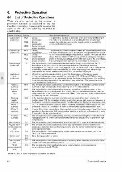
6-1 Protective Operation
6
6. Protective Operation6-1 List of Protective OperationsWhen an error occurs to the inverter, aprotective function is activated to trip theinverter immediately, displaying the name of thealarm at the LED and allowing the motor tocoast to stop.
Name of alarm Display Description of operationOvercurrent OC1 During The protective function is activated when an overcurrent flowing in protection acceleration the motor or a short circuit or ground fault in the output circuit
OC2 During causes the instantaneous inverter output current to exceed the deceleration overcurrent detection level.
OC3 During constant speed operation
Overvoltage OU1 During The protective function is activated when the regenerative power fromprotection acceleration the motor increases to cause the DC link voltage of the main circuit
OU2 During to exceed the overvoltage detection level (Approx. 400 Vdc for 200Vdeceleration class, Approx. 800V for 400V class). When an excessive voltage is
OU3 During constant added to the source voltage, the inverter trips due to the overvoltage,speed operation but inverter protection against the overvoltage is impossible.
Undervoltage LU The protective function is activated when the source voltage drops to cause the DC protection link voltage in the main circuit to become lower than the undervoltage detection
level (Approx. 200 Vdc for 200V class, Approx. 400V for 400V class). If F14 Restart after momentary power failure has been selected, no alarm display is given. If the voltage drops below the control power maintenance level, no alarm is displayed.
Input phase Lin When the inverter is operated while one of the three phases of the power supply loss connected to the main power supply input terminals L1/R, L2/S and L3/T of the main
protection circuit is missing or there is an unbalance among the three-phase voltages, the rectifying diode or smoothing capacitor of the main circuit may be broken. The inverter is stops upon an alarm in these cases.
Heat sink OH1 The protective function is activated when the temperature of the heat sink of the inverter overheat overheat is high because of a broken cooling fan or for other reasons.External OH2 The protective function is activated by a contact signal from an alarm contact of the
alarm external device such as the braking unit, braking resistor, and external thermal overload input relay connected to the control circuit terminal (THR). Or an overheat protective function is
activated by the PTC thermistor.Braking dbH If the electronic thermal overload relay (for braking resistor) has been selected for resistor function code F13, the protective function is activated upon a high operation frequency of
overheat the braking resistor to prevent the resistor from being burned due to the temperature rise.Motor 1 OL1 If electronic thermal overload relay 1 has been selected for function code F10, the overload protective function is activated by a motor current exceeding the set operation level.Motor 2 OL2 If motor 2 has been selected and driven and electronic thermal overload relay 2 has beenoverload selected for function code A06, the protective function is activated by the current in motor
2 exceeding the set operation level.Inverter OLU The protective function is activated by an output current exceeding the overload current overload rating to protect the semiconductor elements in the main circuit of the inverter from high
temperatures.Memory error Er1 The protective function is activated by a data writing error or other errors in the memory.Keypad panel Er2 The protective function is activated when a data transmission error or transmission
communication stoppage is detected between the keypad panel and the control section in the keypad error panel operation mode.
CPU error Er3 The protective function is activated by electric noise or other errors developed in the CPU, or if P24 is overloaded.
Option error Er4 Error during operation of optionEr5
Output phase Er7 The protective function is activated during auto tuning when there is a broken wire or no loss connection in the inverter output circuit.
RS485 Er8 The protective function is activated when a communication error occurs during communication communication through RS485.
error
Table 6-1-1 List of alarm display and protective operations

Protective Operation 6-2
6
6-2 Alarm ResetWhen the inverter trips, remove the cause thenpress the PRG/RESET key on the keypad panelor input a reset command from the RST controlterminal to reset the tripping state. Because thereset command is activated by an edge, supplythe command in an OFF - ON - OFF sequenceas shown in Fig. 6-2-1.When resetting the tripping state, deactivate theoperation command. If the operation commandis left turned on, the inverter starts operationimmediately after the error is reset.
Reset command
Keypad panel display
Alarm output
10 ms or longer
ON
Alarm display
OFF
Regular display(ready to operateOFF
ON OFFOFF
TripFigure 6-2-1
WARNINGIf an alarm reset is made with theoperation signal turned on, a sudden
start will occur. Check that the operationsignal is turned off in advance. Otherwise an accident could occur.

7-1 Troubleshooting
7
7. Troubleshooting7-1 When Protective Function Activates(1) Overcurrent

Troubleshooting 7-2
7
(2) Overvoltage
(3) Undervoltage

7-3 Troubleshooting
6) Inverter overload, motor overload
4) Inverter inside overheat or heat sinkoverheat
(5) Eternal alarm input
7
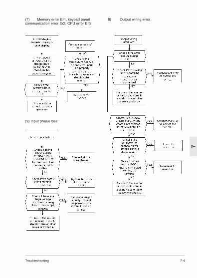
Troubleshooting 7-4
7
(7) Memory error Er1, keypad panelcommunication error Er2, CPU error Er3
8) Output wiring error
(9) Input phase loss

7-5 Troubleshooting
7-2 When Motor rotates Incorrectly(1) The motor does not rotate.
The motor does not start when a coast-to-stopcommand or DC braking command is beinginput.
7

Troubleshooting 7-6
7
(2) The motor rotates but the speed does not change.
The change in the rotation speed of the motor isalso small in the following cases.— "F01 "Frequency command 1" and C30
"Frequency command 2" are set at "3" and asignal is input from both of control terminals12 and C1, and there is no change in the sum of them.
— The load is excessively large and the torquelimit and current limit functions are activated.

7-7 Troubleshooting
7
(3) The motor loses speed during acceleration.
(4) Excessive heat generation from motor

Maintenance and Inspection 8-1
8
8. Maintenance andInspection
Perform daily and periodic inspection to avoidproblems and ensure reliable operation for along time. Take care of the following itemsduring work.8-1 Daily InspectionVisually inspect errors in the state of operationfrom the outside without removing covers whilethe inverter operates or while it is turned on.
1) Check if the expected performance(satisfying the standard specification) isobtained.
2) Check if the surrounding environmentsatisfies the standard specification.
3) Check that the display of the keypad panelis free from errors.4) Check for abnormal noise, excessivevibration or burning smell.5) Check for traces of overheat, discolorationand other defects.
WARNING• Turn the power off and wait for atleast five minutes before starting
inspection. (Further, check that the chargelamp is unlit and measure the DC voltageacross the P (+) and N (-) terminals to checkthat it is lower than 25V.) Otherwise electric shock could occur.• Maintenance and inspection and parts
replacement should be made only byappointed persons. (Take off watch, ringsand other metallic matter before startingwork.) (Use insulated tools.)
• Never modify product.Otherwise electric shock or injuriescould occur.
Table 8-2-1 List of periodic inspection
8-2 Periodic InspectionAfter stopping the operation, turn the power offand remove the front cover to perform periodicinspection.The smoothing capacitor at the DC section ofthe main circuit takes time to be dischargedafter the power is turned off. After checking thatthe charge lamp (CRG) is unlit, check that theDC voltage is lower than the safety level (25VDC) using a multimeter or the like beforestarting work.
Check part Check item How to inspect Evaluation criteriaEnvironment 1) Check the ambient temperature, 1)Check visually or 1) The standard
humidity, vibration and atmosphere measure using specification must be(dust, gas, oil mist, water drops). apparatus. satisfied.2) Check if tools or other foreign 2) Visual inspection 2) No foreign ormatter or dangerous objects are left dangerous objects arearound the equipment. left
Voltage Check if the voltages of the main Measure using a The standard circuit and control circuit are correct. multimeter or the like. specification must
be satisfied.Keypad 1) Check if the display is clear. 1), 2) Visual inspection 1, 2) The display canpanel 2) Check if there is missing parts be read and there is
in the characters. no fault.Structure 1) Abnormal noise and excessive 1)Visual or hearing 1),2),3),4),5)such as vibration inspection No abnormalitiesframe 2) Loose bolts (tightened parts) 2) Retighten
and cover 3) Deformation and breakage 3), 4), 5) Visual4) Discoloration and deformation inspectioncaused by overheat5) Stains and dust
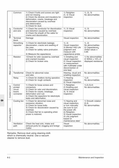
8-2 Maintenance and Inspection
8
Remarks: Remove dust using cleaning clothwhich is chemically neutral. Use a vacuumcleaner to remove dust.
Common 1) Check if bolts and screws are tight 1) Retighten 1), 2), 3)and not missing. 2), 3) Visual No abnormalities2) Check the devices and insulators for inspectiondeformation, cracks, breakage and discoloration caused by overheatand deterioration.3) Check for dust.
Conductor 1) Check the conductor for discoloration 1), 2) Visual 1), 2)and wire and distortion caused by overheat. inspection No abnormalities
2) Check the sheath of the cable forcracks and discoloration.
Terminal Damage Visual inspection No abnormalitiesblockSmoothing 1) Check for electrolyte leakage, 1), 2) 1), 2)capacitor discoloration, cracks and swelling of Visual inspection No abnormalities
the case. 3) Monitor H42 Life 3) Capacitance>2) Check for safety valve protrusion. judgment and (Initial value) x
=
measure with 0.853) Measure the capacitance capacitance probe
Resistor 1)Check for odor caused by overheat 1) Smelling and 1) No abnormalitiesand cracked insulator. visual inspection 2) Within ± 10% of2) Check for broken wire. 2) Visual inspection displayed resistance
or measurementwith multimeter underdisconnection ofone lead
Transformer Check for abnormal noise Hearing, visual and No abnormalitiesand odor. smelling inspection
Relay 1) Check for chatters during operation. 1) Hearing 1),2)2) Check for rough contacts. inspection No abnormalities
2) Visual inspectionControl 1) Check for loose screws and 1) Retighten. 1),2),3),4)printed connectors. 2) Smelling and No abnormalitiescircuit 2) Check for odor and discoloration. visual inspectionboard, 3) Check for cracks, breakage, 3), 4) Visualconnector deformation and rust. inspection
4) Check the capacitors for electrolyte leaks and deformation.
Cooling fan 1) Check for abnormal noise and 1) Hearing and 1) Smooth rotationexcessive vibration. visual inspection, 2),3)2) Check for loose bolts. or turn manually No abnormalities3) Check for discoloration caused by (be sure to turn overheat. the power off)4) Check that fan is operating when 2) Retighten.power is restored. 3) Visual inspection
4) Life judgmentbased on maintenance data*
Ventilation Check the heat sink, intake and Visual No abnormalitiespath exhaust ports for clogging and foreign inspection
matter.
Mai
n ci
rcui
tM
ain
circ
uit
Con
trol
circ
uit
Coo
ling
syst
em

Maintenance and Inspection 8-3
8
• Judgment of life using maintenance dataThe maintenance data of function codes H42and H43 can be used to display data for thejudgment of the capacitance of the capacitor inthe main circuit and the life of the cooling fan toobtain a measure for the judgment of partsreplacement. The capacitor life forecast signal isissued at the Y1 and Y2 terminals according tothe measured capacitance after the capacitanceof the capacity reaches 85%.(1)Measurement of capacitance of capacitor in
main circuitThis inverter is provided with a functionwhere the capacitance of the main circuitcapacitor is automatically measured uponshutoff of the inverter under certainconditions and it is displayed on the keypadpanel upon power-up.The capacitance of the capacitor is displayedin the reduction ratio (% display) of the initialvalue stored inside the inverter beforeshipment.
Procedure of measurement of capacitorcapacitance
1. Remove the optional card from theinverter if it is mounted. Disconnect thebraking unit or direct current bus toanother inverter from the P (+) and N (-)terminals of the main circuit if there isany. The power factor improving reactor(DC reactor) may not be disconnected.
2. Turn the digital inputs (FWD, REV, X1-X5) at the control terminals off.Disconnect the RS 485 communicationterminal if it is connected.
3. Turn the main power supply on. Checkthat the cooling fan rotates. Check thatthe inverter is stopped. (The "OH2external alarm" caused by deactivateddigital input terminals does not cause aproblem.)
4. Turn the main power supply off.5. After the charge lamp is unlit completely,
turn the main power supply on again.6. Monitor function code H42 to check the
capacitor capacitance (%).
(2)Life of cooling fanFunction code H43 indicates the totaloperation time of the cooling fan. The time isintegrated in units of an hour and fractionsshorter than an hour are ignored.The actual life of the fan is largely effected bythe temperature. Take the time as ameasure.
Part Judgment levelMain circuit 85% or lower of the initial capacitor valueCooling fan 30,000 hours (4.0 kW or
less), 25,000 hours (5.5 kW or more) *1
Table 8-2-2 Measure for judgment of life based onmaintenance data
*1: Assumed life of cooling fan at ambientinverter temperature of 40 degree C.

8-4 Maintenance and Inspection
8
8-3 Measurement of Current andVoltage in Main Circuit
Because the voltage and current of the powersupply (input) of the main circuit of the inverterand the output (motor) include harmoniccomponents, the indicated value variesaccording to the type of the meter. Use metersindicated in Table 8-3-1 when measuring withmeters for commercial frequencies.Marketed power factor meters measuring phasedifference between the voltage and currentcannot measure the power factor. To obtain thepower factor, measure the power, voltage and
In case of Single-phase
Table 8-3-1 Meters for measurement of main circuit
Fig 8-3-1 Connection of measuring instruments
In case of Three-phase
Input (power supply) side Output (motor) side Link voltage(P(+)-N(-))
Voltage Current Voltage Current
Ammeter Voltmeter Wattmeter Ammeter Voltmeter Wattmeter DC voltmeterAR,S,T VR,S,T WR,S,T AU,V,W VU,V,W WU,V,W V
Moving iron Rectifier or Digital Moving iron Rectifier Digital Moving coiltype moving iron power type type power type
type meter meter
current on each of the input and output sidesand calculate in the following formula.
Item
Nam
e of
met
erTy
pe o
fm
eter
Sym
bol o
fm
eter
Note) When the output voltage is measured by arectifier type, an error may be included. To increasethe accuracy, use a digital AC power meter.
AU
AV
AW
WU
WW
VU
VV
VW
A W
VPowerSupply
L1/L
L2/N
V+ -
P(+) N(-)
U
V
W
MMotor
VXSM***-1 VXSM***-3
AU
AV
AW
WU
WW
VU
VV
VW
AR
AS
AT
WR
WT
VR
VS
VT
PowerSupply
L1/R
L3/T
L2/S
V+ -
P(+) N(-)
U
V
W
MMotor

Maintenance and Inspection 8-5
8
(2) Do not perform a Megger test or withstandvoltage test to the insulation test controlcircuit of the control circuit. Prepare a highresistance range tester for the control circuit.1) Disconnect all the external wiring from the
control circuit terminals.2) Perform a continuity test to the ground. 1
MΩ or a larger measurement indicates acorrect state.
(3) External main circuit and sequencecontrol circuit
Disconnect all the inverter terminals so thatthe test voltage is not applied.
8-4 Insulation TestBecause an insulation test is made in the factorybefore shipment, avoid a Megger test. If aMegger test is unavoidable, follow theprocedure below. Because a wrong testprocedure will cause breakage of the inverter,take sufficient care.A withstand voltage test will cause breakage ofthe inverter similarly to the Megger test if thetest procedure is wrong. When the withstandvoltage test is necessary, contact IMO.(1) Megger test of main circuit
1) Use a 500 VDC Megger and shut off themain power supply without fail duringmeasurement.
2) If the test voltage leaks to the controlcircuit due to the wiring, disconnect all thecontrol wiring.
3) Connect the main circuit terminals with acommon cable as shown in Fig. 8-4-1.
4) The Megger test must be limited to acrossthe common line of the main circuit andthe ground terminal ( G).
5) MΩ or a larger valuedisplayed at the Megger indicates a correctstate. (The value is for a discrete inverter.)
8-5 Replacement PartsThe life of the part is determined by the type ofthe part. The life of the part varies according tothe environment and operating conditions, andreplacement according to Table 8-5-1 isrecommended.
8-6 Inquiries about Product andGuarantee
(1) When making an inquiryUpon breakage of the product, uncertainties,failure or inquiries, report the followinginformation IMO Precision Controls Ltd.a) Inverter typeb) SER NO. (serial number of equipment)c) Date of purchased) Inquiries (for example, point and extent of
breakage, uncertainties, failurephenomena, and other circumstances)
(2) Guarantee of the productThe product guarantee term is 5 years afterthe purchase or 60 months from the monthand year of production specified on thenameplate, whichever comes first. However,the product will not be repaired free ofcharge in the following cases, even if theguarantee term has not expired.a) The cause includes incorrect usage or
inappropriate repairs or remodeling.b) The product is used outside the standard
specified range.c) The failure is caused by dropping,
damage or breakage duringtransportation after the purchase.
d) The cause is earthquake, fire, storm orflood, lightening, excessive voltage, orother types of act of God or similarevents.
L1/R L2/S L3/T DB P1 P(+) N(-) U
G
V W
Megger
+
Name of part Standard Replacementreplacement method andyears others
Cooling fan 3 years Replace witha new part.
Smoothing 5 years Replace with capacitor a new part.
(Replace afterinspection.)
Electrolytic 7 years Replace withcapacitors new circuiton printed board.circuit board (Replace after
inspection.)Other parts - Determine
after inspection.
Table 8-5-1
Fig 8-4-1

9-1 Specifications
9
*1 The applicable standard motor indicates a 4pole machine.
*2 The rated capacity indicates 230V outputvoltage.
*3 Voltages larger than the source voltagecannot be output.
*4 Amperage values in brackets () areapplicable to operation with 4 kHz or highercarrier frequencies (F26 = 4 or more) orambient temperatures exceeding 40 degree C.
*5 Tests at standard load condition (85% load)*6 Indicates the value when using a DC reactor
(DCR).
Item Detail specificationsInverter typeVXSM 40-1 75-1 150-1 220-1Nominal applied motor *1 [kW] 0.4 0.75 1.5 2.2
Rated capacity *2 [kVA] 1.1 1.9 3.1 4.3 Rated voltage *3[V] Three-phase 200V / 50 Hz, 200V, 220V, 230V / 60 Hz (with AVR function)Rated current *4 [A] 3.0 5.0 8.0 11
(2.5) (4.0) (7.0) (10)Overload capability 150% of rated output current for 1 min.
200% of rated output current for 0.5 sRated frequency [Hz] 50, 60HzPhases, Voltage, Single-phase 200 to 240 V / 50 to 60 Hz *10
FrequencyVoltage/frequency Voltage : +10 to -10% fluctuation Frequency : +5 to -5%Momentary voltage Operation continues at 165V or higher voltage. When the input voltage dip capability *5 drops below 165V from the rated voltage, operation continues for 15 ms.Rated current [A] 3.5 6.5 11.8 17.7(With DCR)(Without DCR) *9 6.4 11.4 19.8 28.5Required power supply 0.7 1.3 2.4 3.6capacity *6 [kVA]Braking torque *7 [%] 70 40Braking torque *8 [%] 150DC braking Starting frequency: 0.0 to 60 Hz, braking current (0 to 100% in 1%
increment), braking time (0.0 to 30.0 s) Enclosure (IEC60529) IP20Cooling method Natural cooling Fan coolingMass [kg] 0.7 1.2 1.8 1.9
9. Specifications9-1 Standard Specifications(1) Single-phase 200V input
Out
put
ratin
gsIn
put
ratin
gsB
raki
ng
*7 Indicates the average braking torque fordecelerating and stopping a discrete motorfrom 60 Hz. (Varies according to theefficiency of the motor.)
*8 Indicates the value with an external brakingresistor (option).
*9 Calculated on assumption that the inverteris connected to 500kVA power supply.
*10 Safe separation for control interface of thisinverter is provided when this inverter isinstalled in overvoltage category II. Basicinsulation for control interface of thisinverter is provided when this inverter isinstalled in overvoltage category III.

Specifications 9-2
9
Item Detail specificationsInverter typeVXSM 40-3 75-3 150-3 220-3 400-3 550-3 750-3Nominal applied motor *1 [kW] 0.4 0.75 1.5 2.2 4.0 5.5 7.5
Rated capacity *2 [kVA] 1.1 1.8 2.6 3.9 6.5 9.3 13Rated voltage *3[V] Three-phase 380,400,415V/50Hz, 380,400,440,460V/60Hz (with AVR function)Rated current *4 [A] 1.5 2.5 3.7 5.5 9.0 13 18
(1.4) (2.1) (3.7) (5.3) (8.7) (12) (16)Overload capability 150% of rated output current for 1 min.
200% of rated output current for 0.5 sRated frequency [Hz] 50, 60HzPhases, Voltage, Three-phase 380 to 480 V / 50 to 60 Hz *11
FrequencyVoltage/frequency Voltage : +10 to -15% Voltage unbalance 2% or less*10
fluctuation Frequency : +5 to -5%Momentary voltage Operation continues at 300V or higher voltage. When the input voltage dip capability *5 drops below 300V from the rated voltage, operation continues for 15 ms.Rated current [A] 0.82 1.5 2.9 4.2 7.1 10.0 13.5(With DCR)(Without DCR) *9 1.8 3.5 6.2 9.2 14.9 21.5 27.9Required power supply 0.6 1.1 2.1 3.0 5.0 7.0 9.4capacity *6 [kVA]Braking torque *7 [%] 70 40 20Braking torque *8 [%] 150DC braking Starting frequency: 0.0 to 60 Hz, braking current (0 to 100% in 1%
increment), braking time (0.0 to 30.0 s) Enclosure (IEC60529) IP20Cooling method Natural cooling Fan coolingMass [kg] 1.1 1.2 1.3 1.4 1.9 4.5
Out
put
ratin
gsIn
put
ratin
gsB
raki
ng
(2) Three-phase 400V input
*1 The applicable standard motor indicates a 4pole machine.
*2 The rated capacity indicates the case for415V output voltage.
*3 Voltages larger than the source voltagecannot be output.
*4 Amperage values in brackets () areapplicable to operation with 4 kHz or highercarrier frequencies (F26 = 4 or more) orambient temperatures exceeding 40 degree C.
*5 Tests at standard load condition (85% load)*6 Indicates the value when using a DC reactor
(DCR).
*7 Indicates the average braking torque fordecelerating and stopping a discrete motorfrom 60 Hz. (Varies according to theefficiency of the motor.)
*8 Indicates the value with an external brakingresistor (option).
*9 Calculated on assumption that the inverter isconnected to 500kVA power supply.
*10 Refer to IEC61800-3 5.2.3.*11 Safe separation for control interface of this
inverter is provided when this inverter isinstalled in overvoltage category II. Basicinsulation for control interface of this inverteris provided when this inverter is installed inovervoltage category III.

9-3 Specifications
9
Item Detail specificationsMaximum 50 to 400 Hz variablefrequencyBase 25 to 400 Hz variablefrequencyStartingfrequency 0.1 to 60.0 Hz variable, Holding time : 0.0 to 10.0s.Carrier 0.75 to 15 kHz (The carrier frequency may automatically drop to 0.75 kHz tofrequency protect the inverter. )
Accuracy Analog setting: Within ± 0.2 % (25 ± 10 °C)Digital setting: Within 0.01% (-10 to +50 °C)
Settingresolution Analog setting: 1/3000 of maximum output frequency
Keypad panel setting: 0.01 Hz (99.99 Hz or lower), 0.1 Hz (100.0 to 400.0 Hz)Link setting : «1/20000 of Maximum frequency
(0.003Hz at 60Hz,0.006Hz at 120Hz,0.02Hz at 400Hz)or 0.01Hz (Fixed)
Voltage/freq. Adjustable at base and maximum frequency, Characteristics with AVR control : 80 to 240 V(200V class),160 to 480V(400V class)Torque boost Automatic:Automatic torque boost can be selected with code setting.
Manual: Setting by codes 1 to 31 (Boost for Variable torque available) Starting torque Starting torque 200% or above
(with dynamic torque vector turned on, during 0.5 Hz operation)DC braking Braking time (0.0 to 30.0 s), braking current (0 to 100%), braking starting
frequency (0.0 to 60.0 Hz) variableControl method Sinusoidal PWM (Dynamic torque vector control) with "current vibration
suppression function" and "dead time compensation function"Operation method Keypad operation: starting and stopping with and keys.
(Keypad panel)Digital input signal: forward (reverse) operation, stop command (3-wire operation
possible), coast-to-stop command, external alarm, errorreset, etc.
Link operation: RS485 (Standard) Profibus-DP,Interbus-S,DeviceNet,Modbus Plus,CAN open (Option)
9-2 Common SpecificationsO
utpu
t fr
eque
ncy
Adj
ustm
ent
Con
trol
RUN STOP

9-4
9
Item Detail specificationsFrequency Keypad operation: key and key.setting
Setting with potentiometer (external potentiometer: 1 to 5 kΩ 1/2 W)Setting with 0 to ± 5 Vdc.Setting with 0 to ± 10 Vdc.Setting with 4 to 20 mAdc.0 to +10 Vdc / 0 to 100% can be switched to +10 to 0 Vdc / 0 to 100% externally.4 to 20 mAdc / 0 to 100% can be switched to 20 to 4 mAdc / 0 to 100% externally.
(UP/DOWN An external signal can be used to control the UP or DOWN command.control)(Multistep Up to 16 different frequencies can be selected by digital input signals.frequency)(Link operation) Link operation : RS485 (Standard)
Profibus-DP,Interbus-S,DeviceNet,Modbus Plus, CAN open (Option)Acceleration / Variable setting in 0.01 to 3600s range. (2 sets of time can be set internally fordeceleration time each of acceleration and deceleration.)(Mode select) Linear, S-curve (weak,strong), Non-linear available.Frequency limiter The high and low frequency limits can be set variably in a 0 to 100% range in Hz.Bias frequency Can be set variably in -400 to 400 Hz range.Gain Can be set variably in a 0 to 200% range.(frequency setting)Jump frequency Three jump frequencies and jump width (0 to 30 Hz) can be set.controlRotating motor Operation without shock is possible.pickup(Flying start)Auto-restart after The motor speed can be detected after power recovery so that the motor is momentary power started at the speed.failureSlip compensation The load during regular operation can be detected for the control of the control frequency. The compensation value can be set variably in a 0.00 to +15.00 Hz
range to the rated frequency. Droop operation The load during regular operation can be detected for the control of the
frequency. The compensation value can be set in a -9.9 to 0.0 Hz range to the rated frequency. (Speed droop characteristics)
Torque limiter When the load torque in the driving or braking mode exceeds the setting, the frequency is controlled to control the load torque to an almost constant level.The limiting torque can be set 20 to 200% and the driving and braking torque values can be independently set. A second set of torque limits can be set.
Con
trol
V
V
Specifications

9-5 Specifications
9
Item Detail specificationsPID control This function can control flowrate, pressure, etc. with analog feedback signal|
The reference and feedback values are displayed in %.Reference signal Keypad operation key and key.: 0.0 to 100%Voltage input (Terminal 12) : 0 to 10VdcCurrent input (Terminal C1) : 4 to 20mAdcMultistep frequency setting : Setting freq./Max. freq.x100%RS485 : Setting freq./Max. freq.x100%Feedback signalTerminal 12 (0 to +10Vdc or +10 to 0Vdc)Terminal C1(4 to 20mAdc or 20 to 4mAdc)
Second motor’s The V/f pattern of the second motor can be internally set for selection by meanssetting of an external signal.
The constant of the second motor can be internally set for selection by means ofan external signal.The electronic thermal overload relay of the second motor can be internally set for selection by means of an external signal.
Energy saving Weak magnetic flux can be set for small loads for operation with an increased operation motor efficiency.During The keypad panel can be extended. (Optional 2m extension cable is available.)operation/stop 7-segment LED display items
• Set frequency • Output frequency • PID setting/feedback value• Output current • Motor r/min• Output voltage • Line speed(A soft filter is provided to attenuate the fluctuation in the displayed value.)A charge lamp indicates power supply.
When setting The function code and data code are displayed.When tripping [The cause of tripping is displayed.]
• OC1 (overcurrent: during acceleration)• OC2 (overcurrent: during deceleration)• OC3 (overcurrent: during constant speed operation)• OU1 (overvoltage: during acceleration)• OU2 (overvoltage: during deceleration)• OU3 (overvoltage: during constant speed operation)• LU (undervoltage)• Lin (input phase loss) (for 3-phase inverter)• dbH (external damping resistor overheat (thermal overload relay))• OH1 (overheat: heat sink)• OH2 (overheat: external thermal overload relay)• OL1 (overload: motor 1)• OL2 (overload: motor 2)• OLU (overload: inverter)• Er1 (memory error)• Er2 (keypad panel communication error)• Er3 (CPU error)• Er4 (option error)• Er5 (option error)• Er7 (output wiring error) (impedance imbalance)• Er8 (RS485 communication error)
During operation, The latest four records of trip history are stored and displayed.when tripping
Con
trol
Dis
play
V
V
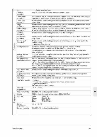
Specifications 9-6
9
Item Detail specificationsOverload Inverter protection electronic thermal overload relayprotectionOvervoltage An excess in the DC link circuit voltage (approx. 400 Vdc for 200V class, approx.protection 800Vdc for 400V class) is detected for inverter protection.Overcurrent The inverter is protected against an overcurrent caused by an overload on theprotection output side.Surge The inverter is protected against a surge voltage penetrating between the powerprotection supply cable of the main circuit and the ground.Undervoltage Voltage drop (approx. 200 Vdc for 200V class, approx. 400Vdc for 400V class)protection in the DC link circuit voltage is detected to stop the inverter.Overheat The inverter is protected against failure of the cooling fan.protectionShort-circuit The inverter is protected against an overcurrent caused by a short-circuit on the protection output side.Ground fault The inverter is protected against an overcurrent caused by ground fault in theprotection output wiring.
* Detection when startingMotor protection Electronic thermal overload relays protect general purpose motors.
The thermal time constant can be adjusted to 0.5 to 10.0 min.Second electronic thermal overload relay can be provided. (Switching with external signal)
Braking resistor Upon an overheat of the damping resistor (external unit), discharging operation protection and inverter operation stopStall prevention • When the output current exceeds the limit during acceleration, the frequency (simple torque limit) ramp is suspended to avoid overcurrent stop.
• When the output current exceeds the setting during constant speed operation, the frequency is decreased to maintain an almost constant torque.• When the DC voltage exceeds the limit during deceleration, the frequency ramp is suspended to avoid overvoltage trip.
Input phase loss The inverter is protected against phase loss of the input voltage.protectionOutput phase loss An unbalance in the impedance of the output circuit is detected to output an protection alarm. (Error during tuning only)Auto reset The number of retries and wait time can be set for a fault trip.Installation location • Indoors
• Places without corrosive gases, flammable gases or dust(degree of pollution: 2)• Places without direct sunlight
Ambient -10 to +50 °CtemperatureRelative humidity 5 to 95% RH (without condensation)Altitude 1000 m Max. (Atmospheric pressure 86 to 106 kPa)Vibration 3mm 2 to 9 Hz
9.8m/s2 9 to 20 Hz2m/s2 20 to 55 Hz1m/s2 55 to 200 Hz
Storage -25 to +65 °CtemperatureStorage humidity 5 to 95% RH (without condensation)
Pro
tect
ion
Env
ironm
ent

9-7 Specifications
9Type Standard External dimensions (mm)
applicablemotor [kW] D D1 D2 D3
VXSM40-1 0.4 118 107 60 32
9-3 External Dimensions

Specifications 9-8
9
Installation screw size : M4 (4 pcs)
Type Standard External dimensions (mm)applicablemotor [kW] D D1 D2 D3
VXSM 75-1 0.75 126 115 62.5 40VXSM 40-3 0.4 126 103 50.5 40VXSM 75-3 0.75 150 115 62.5 64VXSM 150-3 1.5 170 159 86.5 64VXSM 220-3 2.2 170 159 86.5 64
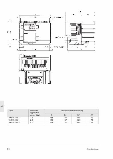
9-9 Specifications
9Type Standard External dimensions (mm)
applicablemotor [kW] D D1 D2 D3
VXSM 150-1 1.5 158 147 94.5 72VXSM 220-1 2.2 158 147 94.5 72VXSM 400-3 4.0 158 147 94.5 72
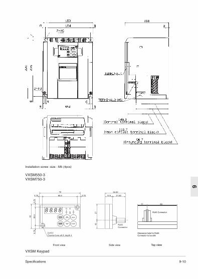
Specifications 9-10
9
Installation screw :size : M5 (4pcs)
VXSM550-3VXSM750-3
70 34.32
21.8212.560.5
2-ø3.2Counter bore ø6.6, depth 4
4.75 4.75
42
2715
32.5
4.75
4.75
Front view Side view
RJ45Connector
RUNP R GRESET
STOPFUNCDATA
RJ45 Connector
17 53
Clearance hole for RJ45Connector to be o26
Top view
VXSM Keypad

9-11 Specifications
9 Note) The branched cable length has to be 1mor less.Switch in the branched inverter has to be OFF.(SW2 OFF)
9-4 RS485 CommunicationRemove the keypad panel of the inverterreferring to section 1-3 (3) and use theconnector having been connected with thekeypad panel to connect up to 31 inverters in aline to perform the following operations.• Frequency setting, forward/reverse rotation,
stop, coast to stop, alarm reset and otheroperations
• Monitoring of output frequency, outputcurrent, operation state, alarm description,and so on
• Setting of function code data (function codedata, command data and monitor data)
The transmission frame is character data havinga fixed length of 16 bytes, so that developmentof programs for the host controller is easy. Theoperation and frequency setting commandrequiring fast speeds can be in a short frame forshorter communication time. The functions ofthe serial communication connector are shownin Table 9-4-1.
Table 9-4-1 Functions of serial communication connector
Terminal Terminall Name of terminal SpecificationNo. symbol4 DX+ RS 485 communication signal Connection of serial communication
(not inverse) signal; compliance with RS4853 DX- RS485 communication signal (inverse)
Fig. 9-4-1 Equivalent circuit of RS485 interface
The leftmost terminal of the connector whenviewed from the front of the inverter is terminal 1.Never connect the terminals other than theabove because signal cables used for thekeypad panel are connected. A terminator isbuilt in the inverter.Turn SW2 on (left side) below the serialcommunication connector for the inverterconnected at the end of the cable to connect theterminator.When you communicate more than one inverter,use a branch adapter in the table 9-4-2 andconnect like Fig 9-4-2.
Fig. 9-4-2 Communication method with more than one inverter
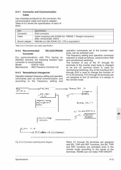
Specifications 9-12
9
Fig. 9-4-3 Command switching block diagram When X1 through X5 terminals are assignedwith BX, THR and RST functions, the BX, THRand RST functions are activated even in theremote mode according to the inputs to theterminals. RS485 can not make THR ON/OFF.
9-4-1 Connector and CommunicationCable
Use marketed products for the connector, thecommunication cable and branch adapter.Table 9-4-2 shows the specification of each ofthem.
Table 9-4-2 Connector and cable specification
9-4-2 Recommended RS-232C/RS485Converter
For communications with PCs having anRS232C terminal, the following isolation typeconverter is recommended.Model : IDACS-1520Manufacture : IMO Precision Controls Ltd
9-4-3 Remote/local changeover
Operation between frequency setting and operationcommands sent via serial communication, andaccording to the frequency setting and
Item SpecificationConnector RJ45 connectorCable Cable complying with EIA568 (for 10BASE-T Straight connection)
(Max. wiring length: 500m)Branch adapter MS8-BA-JJJ (SK KOHKI CO., LTD or equivalent.)
operation commands set in the inverter mainbody, can be switched over.The frequency setting and operation commandselection is made as follows, using function H30and remote/local switching.The function of any of the X1 through X5terminals of the inverter main body is changedto be the LE terminal which is used forremote/local switching. Any of the functions E01through E05 is used to change the function ofX1 to X5 terminal. If X1 through X5 terminals arenot assigned to the LE terminal, it is always inthe remote mode.

9-13 Specifications
9
9-4-4 Communication Protocol
(1) Serial communication specification
Physical level Compliance with EIA RS-485 (2-wire type)Number of connected Host x 1 unit, inverter x 31 units (Station address 1 to 31)stationsTransmission speed 19200, 9600, 4800, 2400, 1200[bit/s]Synchronization method Start-stopTransmission method Half duplexTransmission protocol Polling/selecting, broadcastCharacter type ASCII 7 bitsCharacter length Selection between 7 and 8 bitsTransmission distance Max. 500 mStop bit Selection between 1 and 2 bitsFrame length Standard frame: fixed to 16 bytes, short frame: 8 or 12 bytesParity Selection from none, even and oddError check method Checksum, parity, framing error
Table 9-4-3 Serial communication specification
(2) Transmission protocolIt is the half duplex communication in thepolling/selecting method. The inverter alwayswaits for a write request (selecting) or a readrequest (polling) from the host. The inverter,when receiving in the wait state a request frameto the own station from the host, returns aresponse frame. Upon polling, it returns datatogether. In the case of broadcasting (selectionof all stations in a batch), no response isreturned.
• Broadcast
• Polling/selecting
Response internal time+ (0~10ms) 10 msec or longer

Specifications 9-14
9
(3) Transmission procedure
1) Set communication functions H30 throughH39.
2) Make communication according totransmission frames.
3) If no response returns for one second fromthe inverter upon a frame from the host, retrycommunication. Several retries indicatecertain errors. Make investigation.
4) If no communication is received from the hostfor 30 seconds after the first operationcommand is received, the inverter judges atransmission breakdown error and shutsdown the inverter output, leaving the motor tocoast to stop.
5) After consecutive eight communicationerrors, the inverter output is shut down andthe motor coasts to stop.
(4)Host controller transmission procedureDo not send the next frame unless the responseis returned.If the inverter does not respond for longer thanthe standard time, timeout should be judged andretry should be performed. If a retry is started
before timeout, normal reception may becomeimpossible, so that timeout should be judgedcorrectly. The timeout time is one second in theselecting mode and 0.5 second in the pollingmode. In the retry sequence, send the sameframe again as that sent before no response, orsend a polling (M26: communication errormonitor) frame for reading an error, and checkfor a normal response. (Judge the timeout againduring the check.)If a normal response is returned, a transienttransmission error due to noise or the like isindicated, and correct communication can becontinued. If retries occur frequently, anyabnormalities are probable. In-depthinvestigation is necessary. If no response isreturned, continue retrying. If there are threeretries, there is some trouble in the hardware orsoftware of the host controller. Terminate thesoftware of the host controller and investigate.No error code is returned in the case of negativeacknowledgment of a short frame. Judge theerror code using the communication errormonitor (M26) separately.

9-15 Specifications
9
9-4-5 Standard Frame
The ASCII code character method is employed.A standard frame has a fixed length of 16 bytes.Using optional frames (12 bytes or 8 bytes), the
0 Start-of-heading character (SOH)
1 Tens digit of station address (ASCII)
2 Units digit of station address (ASCII)
3 Enquiry character (ENQ)
4 Command type character (ASCII)
5 Function type character (ASCII)
6 Tens digit of function number (ASCII)
7 Units digit of function number (ASCII)
8 Space (ASCII)
9 First character of data (ASCII)
10 Second character of data (ASCII)
11 Third character of data (ASCII)
12 Fourth character of data (ASCII)
13 End-of-text character (ETX)
14 Upper digit of checksum (ASCII)
15 Lower digit of checksum (ASCII)
Fixed to 01H.Designate a station address of the destinationinverter with 01 to 31 or 99. (ASCII designation ofeach digit)Fixed to 05H.E: Reset command, R: Polling (reading), W:Selecting (writing)"S", "M", "F", "E", "C", "P", "H" or "A" is designated.
Designate a function number using a two-digitnumber. (Designate each digit of 00 to 46 in ASCII.)
Fixed to 20H
The data corresponding to the function is convertedinto a 4-digit hexadecimal, and each digit isdesignated in ASCII.
Fixed to 03HFrom tens digit of the station address to ETX areadded in a binary and the lower two digits of it inhexadecimal notation are stored in ASCII as achecksum.
0 Start-of-heading character (SOH)
1 Tens digit of station address (ASCII)
2 Units digit of station address (ASCII)
3 Response character (ACK/NAK)
4 Command type character (ASCII)
5 Function type character (ASCII)
6 Tens digit of function number (ASCII)
7 Units digit of function number (ASCII)
8 Special additional data (ASCII)
9 First character of data (ASCII)
10 Second character of data (ASCII)
11 Third character of data/tens digit of error code (ASCII)
12 Forth character of data/tens digit of error code (ASCII)
13 End-of-text character (ETX)
14 Upper digit of checksum (ASCII)
15 Lower digit of checksum (ASCII)
Fixed to 01H.
Station address of responding inverter (01 to 31)(ASCII designation of each digit)
06H: Normal responce (ACK), 15H: Faulty response(NAK)E: Reset command, R: Polling (reading), W:Selecting (writing)"S", "M", "F", "E", "C", "P", "H" or "A" is responded(the character transmitted by the host is returned).
The function number is designated in a two-digitnumber. (The number sent by the host is returned.)
Space (20H) or “-” (2DH)
The data sent by the host is returned in normalresponse, or an error code is returned upon anerror.
Fixed to 03HFrom tens digit of the station address to ETX areadded in a binary and the lower two digits of it inhexadecimal notation are stored in ASCII as achecksum.
transmission speed can be increased.Note: Numbers with "H" at the end indicatehexadecimals.
HostInverter frame
InverterHost frame
7(6) 0
7(6) 0

Specifications 9-16
9
0 Start-of-heading character (SOH)
1 Tens digit of station address (ASCII)
2 Units digit of station address (ASCII)
3 Enquiry character (ENQ)
4 Command type character (ASCII)
5 First character of data (ASCII)
6 Second character of data (ASCII)
7 Third character of data (ASCII)
8 Fourth character of data (ASCII)
9 End-of-text character (ETX)
10 Upper digit of checksum (ASCII)
11 Lower digit of checksum (ASCII)
Fixed to 01H.Designate a station address of the destinationinverter with 01 to 31 or 99. (designation of eachcharacter in ASCII)Fixed to 05H.
“a", "e", "f" or "m" is designated.
The data corresponding to the function is convertedinto a four-digit hexadecimal, and each digit isdesignated in ASCII.
Fixed to 03HFrom tens digit of the station address to ETX areadded in a binary and the lower two digits of it inhexadecimal notation are stored in ASCII as achecksum.
HostInverter (selecting)7(6) 0
0 Start-of-heading character (SOH)
1 Tens digit of station address (ASCII)
2 Units digit of station address (ASCII)
3 Response character (ACK/NAK)
4 Command type character (ASCII)
5 End-of-text character (ETX)
6 Upper digit of checksum (ASCII)
7 Lower digit of checksum (ASCII)
Fixed to 01H.Station address of responding inverter (01 to 31)(ASCII designation of each digit)
06H: Normal responce (ACK), 15H: Faulty response(NAK)“a", "e", "f" or "m" sent from the host is returned.
Fixed to 03HFrom tens digit of the station address to ETX areadded in a binary and the lower two digits of it inhexadecimal notation are stored in ASCII as achecksum.
InverterHost frame (selecting)7(6) 0
9-4-6 Short Frame
Short frames are prepared for special functionsto reduce the data transmission time.
(1) Selecting
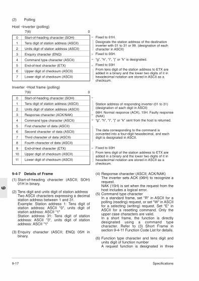
9-17 Specifications
9
0 Start-of-heading character (SOH)
1 Tens digit of station address (ASCII)
2 Units digit of station address (ASCII)
3 Enquiry character (ENQ)
4 Command type character (ASCII)
5 End-of-text character (ETX)
6 Upper digit of checksum (ASCII)
7 Lower digit of checksum (ASCII)
Fixed to 01H.Designate the station address of the destinationinverter with 01 to 31 or 99. (designation of eachcharacter in ASCII)Fixed to 05H.
"g", "h", "i", "j" or "k" is designated.
Fixed to 03HFrom tens digit of the station address to ETX areadded in a binary and the lower two digits of it inhexadecimal notation are stored in ASCII as achecksum.
HostInverter (polling)7(6) 0
(2) Polling
0 Start-of-heading character (SOH)
1 Tens digit of station address (ASCII)
2 Units digit of station address (ASCII)
3 Response character (ACK/NAK)
4 Command type character (ASCII)
5 First character of data (ASCII)
6 Second character of data (ASCII)
7 Third character of data (ASCII)
8 Fourth character of data (ASCII)
9 End-of-text character (ETX)
10 Upper digit of checksum (ASCII)
11 Lower digit of checksum (ASCII)
Station address of responding inverter (01 to 31)(designation of each digit in ASCII)06H: Normal responce (ACK), 15H: Faulty response(NAK)“g", "h", "i", "j" or "k" sent from the host is returned.
The data corresponding to the command isconverted into a four-digit hexadecimal, and eachdigit is designated in ASCII.
Fixed to 03HFrom tens digit of the station address to ETX areadded in a binary and the lower two digits of it inhexadecimal notation are stored in ASCII as achecksum.
InverterHost frame (polling)7(6) 0
9-4-7 Details of Frame
(1) Start-of-heading character (ASCII; SOH)01H in binary.
(2) Tens digit and units digit of station addressTwo ASCII characters expressing a decimalstation address between 1 and 31.Example: Station address 1: Tens digit ofstation address: ASCII "0", units digit ofstation address: ASCII "1"Station address 31: Tens digit of stationaddress: ASCII "3", units digit of stationaddress: ASCII "1"
(3) Enquiry character (ASCII; ENQ) 05H inbinary.
(4) Response character (ASCII; ACK/NAK)The inverter sets ACK (06H) to recognize arequest.NAK (15H) is set when the request from thehost includes a logical error.
(5) Command type characterIn a standard frame, set "R" in ASCII for apolling (reading) request, or set "W" in ASCIIfor a selecting (writing) request. Set "E" inASCII for a resetting command. Only theupper case characters are valid.In a short frame, the function is directlydesignated using a command typecharacter. Refer to (3) Short Frame insection 9-4-11 Function Code List for details.
(6) Function type character and tens digit andunits digit of function numberA request function is designated in three

Specifications 9-18
9
characters. Refer to section 9-4-11 FunctionCode List for details.
(7) Special additional dataThis is normally a space (20H). In aresponse frame issued by an inverter torequest for frequency monitor (M09), aminus sign is set in ASCII during reverserotation output.
(8) DataIn a selecting (writing) request frame sentfrom the host to an inverter, designatewriting data. Refer to section 9-4-10 DataType. In a polling (reading) frame, set spaceor arbitrary letter or number character. in aselecting response frame sent from aninverter to the host, data "0000" or an errorcode is contained, and in a polling frame,data or an error code is contained.
(9) End-of-text character (ASCII; ETX)03H in binary.
(10)Upper digit and lower digit of checksumA binary sum of all the characters from tensdigit of the station address to the end-of-textcharacter is obtained and the lower twodigits of it in hexadecimal notation areexpressed in ASCII codes. Set in the uppercase.Example. When the binary sum is "17EH"The upper digit of the checksum is "7" inASCII. The lower digit of the checksum is "E"in ASCII.
9-4-8 Broadcasting
An operation command or frequencycommand destined to station address "99" isreceived and processed by all the invertersas broadcasting. However, no response isissued by the inverters.

9-19 Specifications
9
The inverter does not return NAK in response toerrors 47 through 49 above. It issues noresponse.In the case of errors 4A through 50, an NAKresponse with an NAK code in the responsecharacter field and the two digit hexadecimalerror code in the data field is returned.The latest error can be referred to using thetransmission error end code monitor (M26).
9-4-10 Data Type(1) In the case of value data
16 bit data is expressed in a hexadecimaland set using four ASCII codes. Concretelyspeaking, the data is between "0000" and"FFFF".Decimal fractions are weighted into integers.Refer to the corresponding section becausethe weight varies according to each piece offunction data. In some functions, thenegative value is expressed in two'scomplement.The bit data is converted into thehexadecimal and expressed.The acknowledgement sent from the inverterin response to a selecting (writing) request isthe writing data. In the negativeacknowledgement, the error code isreturned in two hexadecimal characters.Set "0000" or an arbitrary letters andnumbers in the data to be transmitted to theinverter in a polling (reading) frame.Example: Frequency data, weight 100 times120.00Hz 120Å~100=12000=2EE0H
9-4-9 Communication Error Code
The inverter detects the following errors. The error code is in hexadecimal notation.
Table 9-4-4 Communication error code
Error code Name of error Description(hexadecimal)47H Checksum error The checksum of the frame sent to the own station is in
discrepancy.48H Parity error The parity is in discrepancy.49H Others Reception error other than above (framing, overrun)4AH Format error The enquiry character or the end-of-text character in the
transmitted frame is in an incorrect position.4BH Command error A code other than designated commands (standard and
option) is sent.4EH Function code error A request for an unknown function code is issued.4FH Write disable A write prohibited function or in-operation write prohibited
function is written during operation.50H Data error Data exceeding the standard range is written.
The data is "2" in ASCII, "E" in ASCII, "E" inASCII and "0" in ASCII in order from the firstcharacter to the fourth character.Acceleration time data, weight 10 times6.5 sec: 6.5 x 10 = 65 = 41HThe data is "0" in ASCII, "0" in ASCII, "4" inASCII and "1" in ASCII in order from the firstcharacter to the fourth character.
(2) In the case of bit dataFor bit type data requested by S06, M13 orother functions, the bit data is expressed inhexadecimal notation and each digit istransmitted in ASCII codes.Example: S06 with FWD (bit 0) ON, X1 (bit
2) ON, and X3 (bit 4) ONBit data = 0000 0000 0001 0101 0015H 30H 30H 31H 35H (Hexadecimal) (ASCII)

Specifications 9-20
9Notes)1) Negative values are set in 2's complements.2) When reading S01 or S05, the data
commanded via communication is read outinstead of the command value in the actualoperation. To read the actual commandvalue, read the monitor data.
3) If both S01 and S05 are designated (writtenwith data other than zero), the S01 command
9-4-11 Function Code List
The function code includes the function codesindicated in chapter 5 "Selecting Functions" andthe following functions for the standard andshort frames.(1)Functions for standard frame (commanddata)
Table 9-4-5 Standard frame (command data)
Name Command Function type Data and operationtype character and
numberReset command E 3 spaces Space is transmitted in the data field. The function
resets a protective operation (tripping).Frequency and R/W S01 ±20000d/fmax (Max. frequency)speed commandFrequency R/W S05 0.00 to 400.00 Hz / 0 to 40000 (100 times value)command The inverter operates at the maximum frequency
even if a value larger than the maximum frequency isset by function code F03.A communication command is read in the reading mode.
Operation R/W S06 bit15:RESET 1:ON,0:OFFcommand bits 14 to 7: Fixed to 0
bit6:X5 1:ON,0:OFFbit5:X4 1:ON,0:OFFbit4:X3 1:ON,0:OFFbit3:X2 1:ON,0:OFFbit2:X1 1:ON,0:OFFbit 1: REV (reverse rotation command) 1:ON,0:OFFbit 0: FWD (forward rotation command) 1:ON,0:OFFX1, X2, X3, X4 and X5 function according to function code E01 to E05 settings.
Acceleration time 1 R/W S08 0.0~3600.0s/0~36000 (Value multiplied by 10)
Deceleration time 1 R/W S09 0.0~3600.0s/0~36000 (Value multiplied by 10)
Torque limit level 1 R/W S10 100% (rated torque) / + 10000 (Value multiplied by 100)
Torque limit level 2 R/W S11 100% (rated torque) / + 10000 (Value multiplied by 100)
is effective.4) For the alarm input, "0" indicates a failure.5) X1 through X5 are used for general purpose
inputs; set the function of each terminal usingthe general input terminal setting of theinverter.
6) To cancel the torque limit of S10 and S11,send 7FFFH.
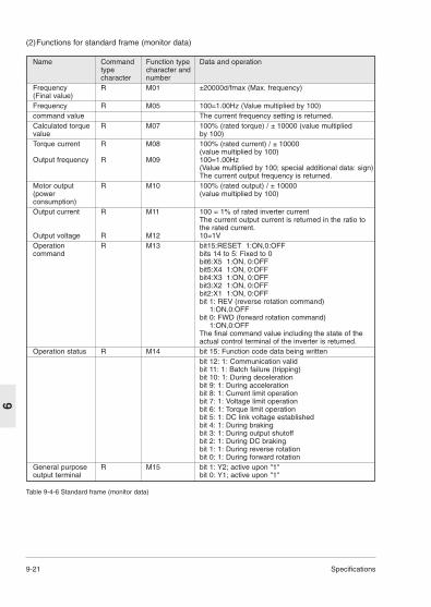
9-21 Specifications
9
(2)Functions for standard frame (monitor data)
Name Command Function type Data and operationtype character andcharacter number
Frequency R M01 ±20000d/fmax (Max. frequency)(Final value)Frequency R M05 100=1.00Hz (Value multiplied by 100)command value The current frequency setting is returned.Calculated torque R M07 100% (rated torque) / ± 10000 (value multiplied value by 100)Torque current R M08 100% (rated current) / ± 10000
(value multiplied by 100)Output frequency R M09 100=1.00Hz
(Value multiplied by 100; special additional data: sign)The current output frequency is returned.
Motor output R M10 100% (rated output) / ± 10000(power (value multiplied by 100)consumption) Output current R M11 100 = 1% of rated inverter current
The current output current is returned in the ratio to the rated current.
Output voltage R M12 10=1VOperation R M13 bit15:RESET 1:ON,0:OFFcommand bits 14 to 5: Fixed to 0
bit6:X5 1:ON, 0:OFFbit5:X4 1:ON, 0:OFFbit4:X3 1:ON, 0:OFFbit3:X2 1:ON, 0:OFFbit2:X1 1:ON, 0:OFFbit 1: REV (reverse rotation command)
1:ON,0:OFFbit 0: FWD (forward rotation command)
1:ON,0:OFFThe final command value including the state of the actual control terminal of the inverter is returned.
Operation status R M14 bit 15: Function code data being writtenbit 12: 1: Communication validbit 11: 1: Batch failure (tripping)bit 10: 1: During decelerationbit 9: 1: During accelerationbit 8: 1: Current limit operationbit 7: 1: Voltage limit operationbit 6: 1: Torque limit operationbit 5: 1: DC link voltage establishedbit 4: 1: During brakingbit 3: 1: During output shutoffbit 2: 1: During DC brakingbit 1: 1: During reverse rotationbit 0: 1: During forward rotation
General purpose R M15 bit 1: Y2; active upon "1"output terminal bit 0: Y1; active upon "1"
Table 9-4-6 Standard frame (monitor data)

Specifications 9-22
9
Name Command Function type Data and operationtype character andcharacter number
Failure description; R M16current oneFailure description; R M17previous oneFailure description; R M18 Refer to (4) Alarm display dataone beforeprevious oneFailure description; R M19one before twoprevious onesTotal operation R M20 0 to 65535 / 0 to 65535 hourstimeDC link voltage R M21 0 to 500 / 0 to 500V (200V class)monitor 0 to 1000 / 0 to 1000V (400V class)Function code R M23 4112H = VXSM-1
4114H = VXSM-3Capacity code R M24 1=0.01kWROM version R M25 0 to 99: Standard, > 100: Non-standardTransmission error R M26 Refer to section 9-4-9. The latest error is returned. handling code The communication error is initialized when the power
is turned off.Main circuit R M46 1=0.1%capacitor lifeCooling fan life R M48 1=1 hour
Note)1) Output frequency monitoring (M09, M35) addsan ASCII code for forward rotation (space), reverserotation (minus) and stop (space) as direction ofrotation data, and handled as 5-byte data.

9-23 Specifications
9
(3) Functions for short frame
Table 9-4-7 Short frame
(4) Alarm display dataThe failure description (alarm description) is asshown in the table below. The failure code is inthe hexadecimal notation.
Table 9-4-8 Failure description
Function Command Data direction Data range; transmission Change type data / actual data duringcharacter operation
Frequency command a Selecting Same as S01 -Frequency command e Selecting Same as S05 -Operation command f Selecting Same as S06 -Reset command m Selecting 4 spaces -Calculated torque h Polling Same as M07 -value monitorTorque current I Polling Same as M08 -monitorOutput frequency j Polling Same as M09; no sign . -monitor is attachedOperation state k Polling Same as M14 -monitor
Failure Description Indication Failure Description Indication code on panel code on panel0000 No alarm --- 0012 External alarm OH20001 Overcurrent, during OC1 0016 Braking resistor dbH
acceleration overheat0002 Overcurrent, during OC2 0017 Motor 1 overload, OL1
deceleration0003 Overcurrent, during OC3 0018 Motor 2 overload, OL2
constant speedoperation
0006 Overvoltage, during OU1 0019 Inverter overload OLUacceleration
0007 Overvoltage, during OU2 001F Memory error Er1deceleration
0008 Overvoltage, during OU3 0020 Keypad panel Er2constant speed communication erroroperation
000A Undervoltage LU 0021 CPU error Er3000B Input phase loss Lin 0025 Output phase loss error Er7
loss error0011 Heat sink overheat OH1 0026 RS485 communication Er8
error

Specifications 9-24
9
9-4-12 Data format
The data format of each piece of function codedata of the inverter is defined here.Prepare data according to the format numberedin the data format for each function code. (Referto section 5-1 Function Setting List and section9-4-11 Function Code List for the data format.)The data field of the transmission frame exceptfor data format 10 consists of a 4-digit ASCIIcode converted from a 4-digit hexadecimal dataas shown in the figure below. For details of eachformat, refer to the following data formats (1)through (11).
15 14 13 12 11 10 9 8 7 6 5 4 3 2 1 0
4-digit hexadecimal data => 4-digit ASCII code
(1) Data format 016-bit binary code, least increment 1, positivevalue only.Example) In the case that F15: (frequencylimiter, upper limit) = 60 Hz60 x 1 = 60 (dec.) = 003C (hex.), hence: 003C
(2) Data format 116-bit binary code, least increment 1,positive/negative valueThe negative value is expressed in 2'scomplement. -1 -> FFFF (hex.)Example: In the case that F18: (bias frequency)= -20 Hz-20 x 1 = -20 (dec.) = FFEC (hex.), hence: FFEC
(3) Data format 216-bit binary code, least increment 0.1, positivevalue onlyExample) In the case that F17: (gain frequencysetting signal) = 100.0%100.0 x 10 = 1000 (dec.) = 03E8 (hex.), hence:03E8
(4) Data format 316-bit binary code, least increment 0.1,positive/negative valueThe negative value is expressed in 2'scomplement. -1 FFFF (hex.)Example: In the case that C31: (analog inputoffset adjustment, terminal 12) = -5.0%-5.0 x 10 = -50 (dec.) = FFCE (2's complement)
(5) Data format 416-bit binary code, least increment 0.01,positive value onlyExample) In the case that C05: (multistepfrequency 1) = 50.25 Hz50.25 x 100 = 5025 (dec.) = 13A1 (hex.), hence:13A1
(6) Data format 516-bit binary code, least increment 0.01,positive/negative valueThe negative data is expressed in 2'scomplement. -1 -> FFFF (hex.)Example: In the case that M07: (actual torque) =-85.38%
-85.38 x 100 = -8538 (dec.) = DEA6(hex.), hence: DEA6
0 0 3 C
F F C E
1 3 A 1
D E A 6
F F E C
0 3 E 8

9-25 Specifications
9
(7) Data format 6Acceleration/deceleration time, amperage data
15 14 13 12 11 10 9 8 7 6 5 4 3 2 1 0
0 0 0 0 Index Data field
15 14 13 12 11 10 9 8 7 6 5 4 3 2 1 0
0 0 0 0 0 0 0 0 X5 X4 X3 X2 X1
Polarity Unused0 : 0.01 x 001~999 (0.01~9.99)1 : 0.1 x 100~999 (10.0~99.9)2 : 1 x 100~999 (100~999)3 : 10 x 100~360 (1000~3600)
0: Positive (+), 1: Negative (-)
Example: In the case that F07: communication No. (acceleration time 1) = 20.0 seconds20.0 = 0.1 x 200, hence: 04C8
0 4 C 8
(8) Data format 8Operation command
RE
SE
T
RE
V
FW
D
Unused General-purpose FWD: forward rotation input command,
REV: reverse rotation command
(All bits: "1" when turned on)
Example: In the case that M13: (operation command) = 0000 0000 0100 0101 (bin.): FWD, X1,X5 = ON
M13 = 0045 (hex.), hence: 0045
0 0 4 5

Specifications 9-26
9
15 14 13 12 11 10 9 8 7 6 5 4 3 2 1 0
0 0 0 0 0 0 0 0 0 0 0 0 0 0 X2 X1
(9) Data format 9General-purpose output terminal
Unused General-purpose input
(All bits: "1" when turned on)
Example: In the case that M15: (general-purpose output terminal) = 0000 0000 0000 0001 (bin.):Y1 = ON
M15 = 0001 (hex.), hence: 0001
0 0 0 1
15 14 13 12 11 10 9 8 7 6 5 4 3 2 1 0
–
RE
SE
T
RL
ALM
DE
C
AC
C
IL VL
TL
NU
V
BR
K
INT
EX
T
RE
V
FW
D
(10) Data format 10Operation state
(All bits: "1" when turned on or active)FWD: During forward rotationREV: During reverse rotationEXT: During DC brakingINT: Inverter shutdownBRK: During brakingNUV: DC link establishedTL: Torque limit operationVL: Voltage limit operationIL: Current limit operationACC: During accelerationDEC: During decelerationALM: Batch alarmRL: Transmission valid/invalidBUSY: During data writing (processing)
Example) ... Omitted (The monitoring method is similar to format 8.)

9-27 Specifications
9
(11) Data format 1116-bit binary code, least increment 0.01,positive/negative data (5-byte ASCII code)
ASCII code 4-digit hexadecimal data 4-digit ASCII code(of minus sign
19 18 17 16 15 14 13 12 11 10 9 8 7 6 5 4 3 2 1 0
Example: In the case that M09 (output frequency) = +60.00 Hz60.00 ¥ 100 = 6000 (dec.) = 1770 (hex.), hence:
Positive data is handled in a 4-byte ASCII code similarly to data format 0.• In the case that M09 (output frequency) = -60.00 Hz
60.00 x 100 = 6000 (dec.) = 1770 (hex.). An ASCII code of the minus sign is added at the top.: -1770
(12) Data format 12Data format for P04, A13 (auto tuning)
1 7 7 0
– 1 7 7 0
15 14 13 12 11 10 9 8 7 6 5 4 3 2 1 0
0 0 0 0 0 0 0 0 0 0 0 0 * *RE
V
FW
D
Unused (fixed to “0”) Unused (fixed to “0”) Data field
Communication H30 settingdata 0 or 1 2 or 3(P04 or A13) Operation command
Keypad panel Terminal block RS4850000H ACK: However, no operation ACK: However, no operation NAK0100H NAK NAK ACK: However, no
operation0200H NAK NAK ACK: However, no
operation0300H NAK NAK NAK0001H NAK Note 1 NAK0101H NAK NAK Note 20201H NAK NAK Note 20301H NAK NAK NAK0002H NAK Note 1 NAK0102H NAK NAK Note 20202H NAK NAK Note 20302H NAK NAK NAK
Note 1: Tuning is started upon a terminal blockoperation command. After tuning is completed,an ACK response is given. (The ACK responseis given before the terminal block is turned off.)
Note 2: After data is written via RS485, tuningis started. After tuning is completed, an ACKresponse is given. (The operation command isautomatically turned off.)

Options 10-1
10
10. Options10-1 External Options
Table 10-1-1 External options
Molded case The molded case circuit breaker (MCCB) is connected for the protection of circuit breaker the main circuit wiring up to the inverter and for turning the power on and off.
The rated current or the rated interrupting capacity varies according to the power supply specifications.
DC reactor (DCR) Connect in the following cases.(1) When the power supply transformer capacity exceeds 500 kVA.(2) When a thyristor load is connected to the same power supply or when the
capacitor for power factor improvement is turned on or off.(3) When the unbalance rate between phases of the source
voltage exceeds 2%.
Unbalance rate (Max. voltage [V] - (Min. voltage [V]between phases = x 67[%]
(Average voltage of three phases [V]
(4) To reduce the harmonic current in the input.The input power factor can be improved to 0.9 to 0.95.
Magnetic contactor The inverter can be operated without an electromagnetic contactor. Connect (MC) one to turn the power off for the safety after the protective function of the
inverter is activated.Surge absorber Connect to suppress the surge generated when the electromagnetic
contactors, control relays or other exciting coils are opened or closed.Reactor for radio Use for noise reduction when electric noise interference is caused to radios noise reduction or electronic devices near the inverter.Frequency setting Connect to set the frequency from the control circuit terminals using the potentiometer inverter power supply.
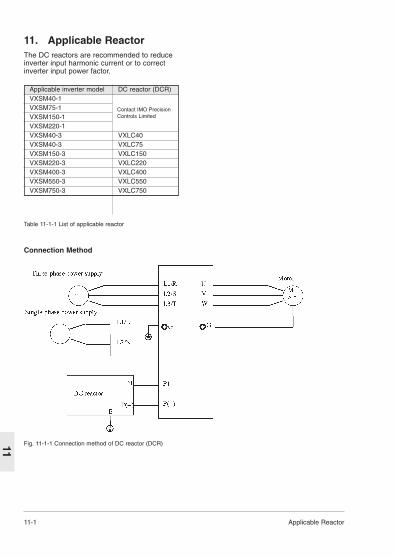
11-1 Applicable Reactor
11
11. Applicable ReactorThe DC reactors are recommended to reduceinverter input harmonic current or to correctinverter input power factor.
Table 11-1-1 List of applicable reactor
Applicable inverter model DC reactor (DCR)VXSM40-1VXSM75-1VXSM150-1VXSM220-1VXSM40-3 VXLC40VXSM40-3 VXLC75VXSM150-3 VXLC150VXSM220-3 VXLC220VXSM400-3 VXLC400VXSM550-3 VXLC550VXSM750-3 VXLC750
Fig. 11-1-1 Connection method of DC reactor (DCR)
Connection Method
Contact IMO PrecisionControls Limited

Electromagnetic Compatibility 12-1
12
Applied Rated Max. Max. motor cable lengthInverter Filter Type Current Rated EN55011 EN55011
Voltage Class B Class A
VXSM40-1 RFM40-1 6.5A
VXSM75-1 RFM75-1 12A
VXSM150-1
VXSM220-1
VXSM40-3
VXSM75-3 10m 50m
VXSM150-3
VXSM220-3
VXSM400-3 RFM400-3 15A
VXSM550-3
VXSM750-3
12. ElectromagneticCompatibility (EMC)
12-1GeneralIn accordance with the provisions described in
the European Commission Guidelines Documenton Council Directive 89/336/EEC,IMO PrecisionControl Ltd. have chosen to classify the VXSMrange of inverters as "Complex Components".
Classification as "Complex Components"allows a product to be treated as an "apparatus",and thus permits compliance with the essentialrequirements of the EMC Directive to bedemonstrated to both an integrator of VXSMinverters and to his customer or the installer andthe user.
Jaguar VXSM inverters are supplied `CE-marked', signifying compliance with EC Directive89/336/EEC when fitted with specified filter unitsinstalled and earthed in accordance with this sheet.
This Specification requires the followingperformance criteria to be met.
EMC product standard EN61800-3/1997
Immunity : Second environment(Industrial environment )
Emission : First environment (Domesticenvironment )
Finally, it is customer’s responsibility tocheck whether the equipment conforms toEMC directive.12-2 Recommended Installation
InstructionsFor conformance with the EMC Directive,
these instructions must be followed. Follow the usual safety procedures whenworking with electrical equipment. All electricalconnections to the filter, Inverter and motor mustbe made by a qualified electrical technician.1) Use the correct filter according to Table 12-
2-1. 2) Install the Inverter and filter in theelectrically shielded metal wiring cabinet. 3) The back panel of the wiring cabinet of
board should be prepared for the mountingdimensions of the filter. Care should betaken to remove any paint etc. from themounting holes and face area of the panel.This will ensure the best possible earthingof the filter.
4) Use screened cable for control, motor andother main wiring which is connected to theinverter, and these screens should besecurely earthed (at both ends in case ofmotor cable).
5) It is important that all wire lengths are keptas short as possible and that incomingmains and outgoing motor cables are keptwell separated.
" To minimize the conducted radiodisturbance in the power distributionsystem, the length of the motor-cable shouldbe as short as possible. "
Table 12-2-1 RFI filters
Note: The above data may be subject to changewithout notice. If in doubt contact IMO PrecisionControls Ltd, before specifying.
Note: For details, refer to IMO Precision Controls Ltd.
RFM220-1
RFM220-3
RFM750-3
29A
10A
30A
230Vac/1ph
415Vac/
3ph
IMO JAGUAR DRIVES5 YEAR WARRANTY
CopyrightAll rights reserved. No part of this publication may be produced or transmitted in any form or byany means, electronic or mechanical including photocopying, recording, or by any information
storage or retrieval system without the written permission of IMO Precision Controls Ltd
© IMO Precision Controls Ltd 2001
IMO JAGUAR Drives are covered by a unique5 year warranty against failure arising as a resultof inferior material or workmanship.
In the event of a unit failing within 5 years ofdespatch from IMO, we will repair or replace thedrive free of charge.
When possible, in the interest of providing thefastest service to our customers, we will replacethe failed drive with a new or service exchangeunit at IMO’s discretion. This may not bepossible, however, if the failed unit is in poorcondition owing to abuse or neglect. In suchcircumstances, the customer may elect to havethe unit repaired within the warranty if viable,but physical refurbishment will be chargeable.
IMO will, upon request, provide a serviceexchange unit in advance of receipt of the failedunit if the order number is provided along withdetails of the failed unit. Replacements will bedespatched at IMO’s cost and credit will beissued upon receipt of the failed unit in goodphysical condition. Full credit will not be givenif in IMO’s judgement the unit has beenphysically or electrically abused. A no-faultfound charge will be levied upon units returnedand found not to be faulty.
The terms of the warranty do not provide for onsite service although a service engineer will beprovided upon receipt of an order. IMO mayelect to waive any charge should the findings onsite indicate that any problem found lies withinthe scope of the warranty.
DocumentationEvery effort has been made by IMO PrecisionControls Ltd to ensure that this documentaccurately and completely represents the JaguarVXSM range of inverters at the time of going topress. Information with respects to installation isnecessarily generalised, and the supplier acceptsno liability for contingencies over which he hasno control in respect of the selection, installationand/or operation of equipment.
Out of hours telephone contacts:Product Support 07831 207220
07831 207221

IMO Precision Controls Limited1000 North Circular RoadStaples Corner, London NW2 7JP
Telephone: +44 (0)20 8452 6444Fax: +44 (0)20 8452 3512
Web: www.imopc.comEmail: [email protected]
Out-of-hours telephone contacts
Product support07831 20722007831 207221


![DANGERS TO THE SOUL. 2 EMOTIONAL DANGERS [CONCERNS/ATTITUDES]](https://img.pdfslide.net/doc/110x75/5a4d1ad17f8b9ab0599717e6/dangers-to-the-soul-2-emotional-dangers-concernsattitudes.jpg)