Embed Size (px)
Citation preview

1/8www.burkert.com
5411
Type 5411 is a pilot operated 3/2-way solenoid valve with manual override as standard. The body includes a servo piston with the seat seals. Through pilot channels, the servo piston is either loaded with input pressure or released. A minimum pressure difference of 1 bar is required for switching. The vent port is integrated as a sintered bronze silencer directly in the valve body. The valves can be combined (up to 6 valves) on a single-channel manifold with common pressure supply.
• Robust servo-piston valve
• Service-friendly manual override
• Single or block assembly
• Explosion-proof versions available
3/2-way solenoid valve for pneumatic applications
Technical dataOrifice DN6.0 mmPort connection G ¼Body material Polyamide (reinforced) with moulded-in brass threadsCoil material Polyamide, EpoxySeal material NBRMedium neutral medium, e.g. lubricated or unlubricated compressed
airAir pressure quality ISO 8573 - 1:2010, class 7.4.4*Medium Temperature - 10 °C to + 60 °CMedium pressure 1 to 10 barAmbient Temperature max. 55 °CQNn-Value air 900 l/minOperating voltage 24 V DC
24/110/230 V, 50 - 60 HzVoltage tolerance ± 10 %Power consumption
version with V DC voltage version with V AC voltage
2 W 11 VA (inrush), 6 VA (hold)
Response timeopening closing
50 ms (Pressure rise 0 to 90 %) 30 ms (Pressure drop 100 to 10 %)
Duty cycle 100 % ED continuously ratedElectrical connection Tag connectors according to DIN EN 175301 - 803 (previ-
ously DIN 43650) Form A for cable plug Type 2508Schutzart IP65 with cable plugInstallation As required, preferably with solenoid system upright; Air
exhausted from the relief port with pressed sintered bronze silencer must not be impeded.
Flow rate: QNn-value air [l/min]: Measured at + 20 °C, 6 bar pressure at valve inlet and 1 bar pressure difference.Pressure ranges [bar]: Overpressure to the atmospheric pressure* To prevent freezing of the expanded compressed air, the pressure dew point must be at least 10 K lower than the
temperature of the medium.
Circuit function C
122(A)
1(P) 3(R)
3/2 way servo-con-trolled solenoid valve,normally closed
Circuit function D
2(B)
1(P) 3(R)
103/2 way servo-con-trolled solenoid valve,normally open
5411
2/8
Materials
1
2
3
4
5
6
89
10
7
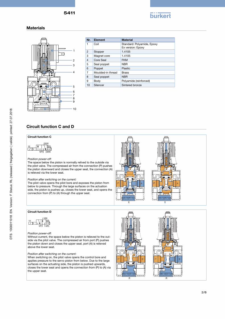
Nr. Element Material1 Coil Standard: Polyamide, Epoxy
Ex version: Epoxy2 Stopper 1.41053 Magnet core 1.41054 Core Seal FKM5 Seal poppet NBR6 Poppet Plastic7 Moulded-in thread Brass8 Seal poppet NBR9 Body Polyamide (reinforced)10 Silencer Sintered bronze
Circuit function C and D
Circuit function C
122(A)
1(P) 3(R)
Position power-off:The space below the piston is normally relived to the outside via the pilot valve. The compressed air from the connection (P) pushes the piston downward and closes the upper seat, the connection (A) is relieved via the lower seat.
Position after switching on the current:The pilot valve opens the pilot bore and exposes the piston from below to pressure. Through the large surfaces on the actuation side, the piston is pushes up, closes the lower seat, and opens the connection from (P) to (A) through the upper seat.
Circuit function D
2(B)
1(P) 3(R)
10
Position power-off:Without current, the space below the piston is relieved to the out-side via the pilot valve. The compressed air from port (P) pushes the piston down and closes the upper seat, port (A) is relieved above the lower seat.
Position after switching on the current:When switching on, the pilot valve opens the control bore and applies pressure to the servo piston from below. Due to the large surfaces on the actuating side, the piston is pushed upwards, closes the lower seat and opens the connection from (P) to (A) via the upper seat.
5411
3/8
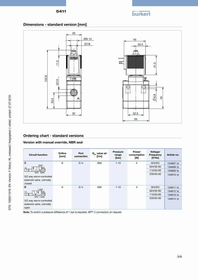
Dimensions - standard version [mm]
41.
3
6.8
45
32.5
55
45
20.5 G1/8
SW 14
32
122
.6
G1/
4
33.
5
32
11.
2
Ordering chart - standard versions
Version with manual override, NBR seal
Circuit function Orifice[mm]
Port connection
QNn value air [l/m]
Pressure range[bar]
Power consumption
[W]
Voltage/ Frequency
[V/Hz]Article no.
C
122(A)
1(P) 3(R)
3/2 way servo-controlledsolenoid valve, normally closed
6 G ¼ 900 1-10 2 024/DC 134607 024/50-60 134608 110/50-60 134609 230/50-60 134610
D2(B)
1(P) 3(R)
10
3/2 way servo-controlled solenoid valve, normally open
6 G ¼ 900 1-10 2 024/DC 134611 024/50-60 134612 110/50-60 134613 230/50-60 134614
Note: To switch a pressure difference of 1 bar is required. NPT ¼ connection on request.
5411
4/8
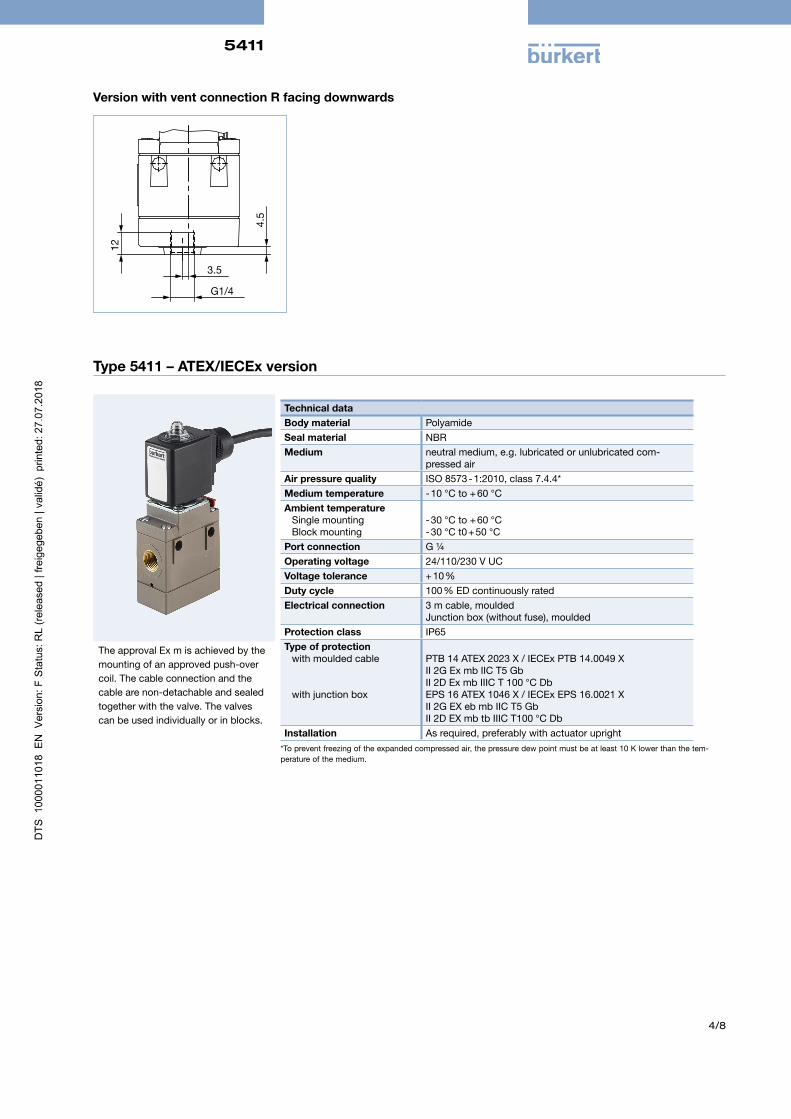
Version with vent connection R facing downwards
4.5
G1/4
3.5
12
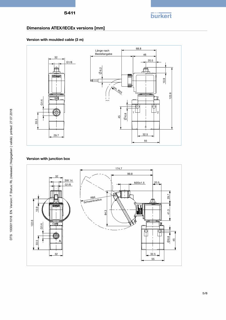
Type 5411 – ATEX/IECEx version
Technical dataBody material PolyamideSeal material NBRMedium neutral medium, e.g. lubricated or unlubricated com-
pressed airAir pressure quality ISO 8573 - 1:2010, class 7.4.4*Medium temperature - 10 °C to + 60 °CAmbient temperature
Single mountingBlock mounting
- 30 °C to + 60 °C- 30 °C t0 + 50 °C
Port connection G ¼Operating voltage 24/110/230 V UCVoltage tolerance + 10 %Duty cycle 100 % ED continuously ratedElectrical connection 3 m cable, moulded
Junction box (without fuse), mouldedProtection class IP65Type of protection
with moulded cable
with junction box
PTB 14 ATEX 2023 X / IECEx PTB 14.0049 XII 2G Ex mb IIC T5 GbII 2D Ex mb IIIC T 100 °C DbEPS 16 ATEX 1046 X / IECEx EPS 16.0021 XII 2G EX eb mb IIC T5 GbII 2D EX mb tb IIIC T100 °C Db
Installation As required, preferably with actuator upright*To prevent freezing of the expanded compressed air, the pressure dew point must be at least 10 K lower than the tem-perature of the medium.
The approval Ex m is achieved by the mounting of an approved push-over coil. The cable connection and the cable are non-detachable and sealed together with the valve. The valves can be used individually or in blocks.
5411
5/8
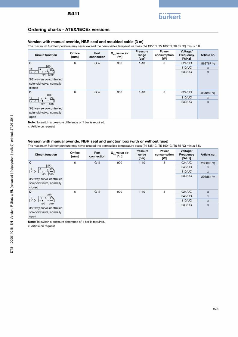
Dimensions ATEX/IECEx versions [mm]
Version with moulded cable (3 m)
G1/8
32
G1/
4
33.
5
29.7 32.5
55
6.
8
45
122
.6
10.
9
Bestellangabe
6.
2
20.5
68.8
min. R25
46
1 2
3
Länge nach
Version with junction box
29.
7 4
1.3
84.
3
6.
8
45
32.5
55
R84
Schwenkradius
M20x1.5 20.5
174.7
G1/8
SW 14
32
10.
9
122
.6
G1/
4
33.
5
32
99.8
5411
6/8
Ordering charts - ATEX/IECEx versions
Version with manual overide, NBR seal and moulded cable (3 m)The maximum fluid temperature may never exceed the permissible temperature class (T4 135 °C, T5 100 °C, T6 85 °C) minus 5 K.
Circuit function Orifice[mm]
Port connection
QNn value air l/m]
Pressure range[bar]
Power consumption
[W]
Voltage/ Frequency
[V/Hz]Article no.
C
122(A)
1(P) 3(R)
3/2 way servo-controlledsolenoid valve, normally closed
6 G ¼ 900 1-10 3 024/UC 566767 110/UC x230/UC x
D2(B)
1(P) 3(R)
10
3/2 way servo-controlled solenoid valve, normally open
6 G ¼ 900 1-10 3 024/UC 331882 110/UC x230/UC x
Note: To switch a pressure difference of 1 bar is required.x: Article on request
Version with manual overide, NBR seal and junction box (with or without fuse)The maximum fluid temperature may never exceed the permissible temperature class (T4 135 °C, T5 100 °C, T6 85 °C) minus 5 K.
Circuit function Orifice[mm]
Port connection
QNn value air l/m]
Pressure range[bar]
Power consumption
[W]
Voltage/ Frequency
[V/Hz]Article no.
C
122(A)
1(P) 3(R)
3/2 way servo-controlledsolenoid valve, normally closed
6 G ¼ 900 1-10 3 024/UC 288806 048/UC x110/UC x230/UC 295864
D2(B)
1(P) 3(R)
10
3/2 way servo-controlled solenoid valve, normally open
6 G ¼ 900 1-10 3 024/UC x048/UC x110/UC x230/UC x
Note: To switch a pressure difference of 1 bar is required.x: Article on request
5411
7/8
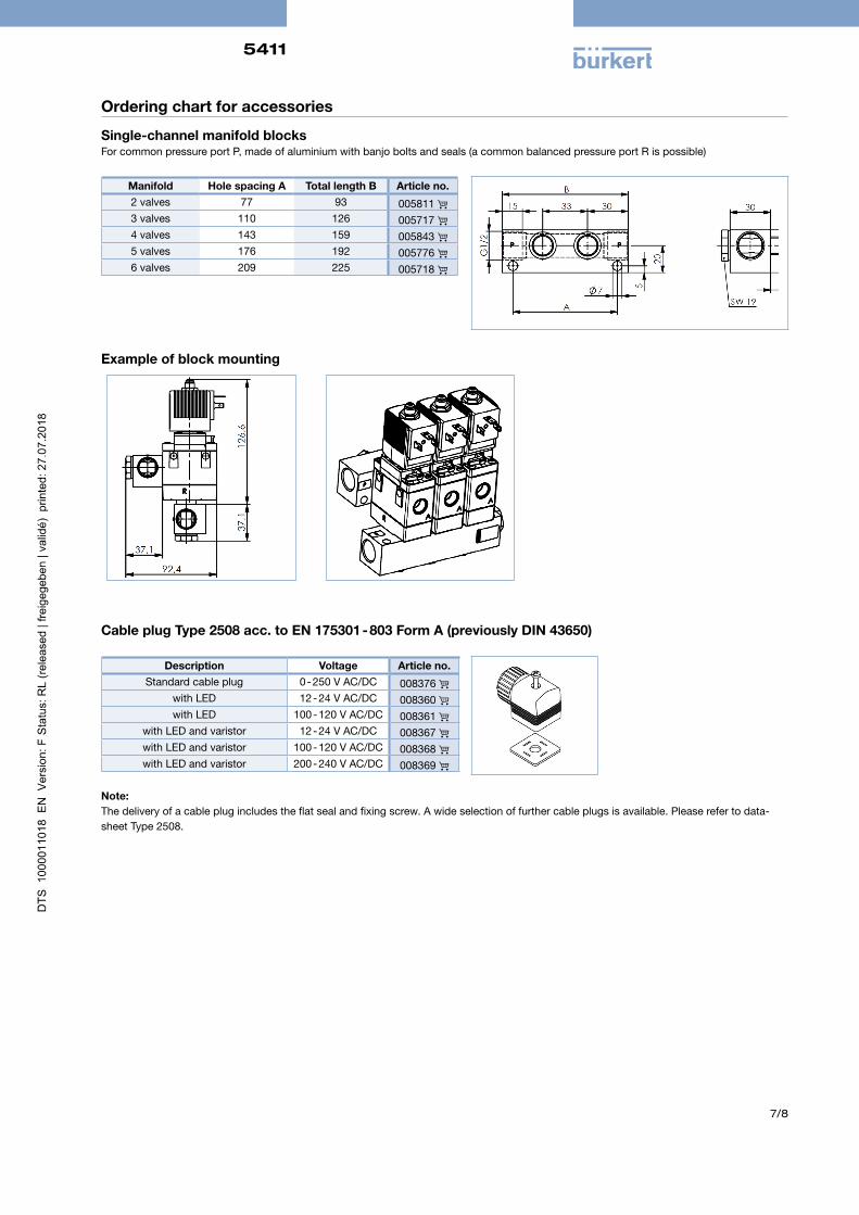
Ordering chart for accessories
Single-channel manifold blocks For common pressure port P, made of aluminium with banjo bolts and seals (a common balanced pressure port R is possible)
Manifold Hole spacing A Total length B Article no.2 valves 77 93 005811 3 valves 110 126 005717 4 valves 143 159 005843 5 valves 176 192 005776 6 valves 209 225 005718
Example of block mounting
Cable plug Type 2508 acc. to EN 175301 - 803 Form A (previously DIN 43650)
Description Voltage Article no.Standard cable plug 0 - 250 V AC/DC 008376
with LED 12 - 24 V AC/DC 008360 with LED 100 - 120 V AC/DC 008361
with LED and varistor 12 - 24 V AC/DC 008367 with LED and varistor 100 - 120 V AC/DC 008368 with LED and varistor 200 - 240 V AC/DC 008369
Note: The delivery of a cable plug includes the flat seal and fixing screw. A wide selection of further cable plugs is available. Please refer to data-sheet Type 2508.

5411
8/8
In case of special application conditions,please consult for advice.
We reserve the right to make technical changes without notice.© Christian Bürkert GmbH & Co. KG 1807/5_DE-de_00891715
To find your nearest Bürkert office, click on the orange box www.burkert.com
Ex-Cable gland(Polyamide version included in delivery / surcharge applied for brass nickel plated version.
Photo DescriptionEx Approvals
Article no DrawingCertification Identification
Brass. nickelplated,
6-13 mm
PTB 04 ATEX 1112 X, IECEx PTB
13.0027X
II 2 G Ex e IIC Gb,II 2 D Ex tb IIIC Db
IP68
773278 TL 29-37 mmL 6 mmD 20
SW 24 mmE 27 mm
Polyamide,7-13 mm
PTB 13 ATEX 1015 X, IECEx PTB
13.0034X
II 2 G Ex e IIC Gb, II 2 D Ex tb IIIC Db
IP68
773277 TL 36-45 mmL 10 mmD 20
SW 24 mmE 28 mm
Special tool to turn the junction box (not included in delivery)
Photo Description Article no.
Set SC02-AC10Special wrenchService Manual
293488
Fuse for terminal box
Voltage [V] Max. current [A] Article no.24 0.4 153734 230 0.63 153717