Embed Size (px)
Citation preview

PX
User Manual
Issue D
PX User Manual – Issue D
- 2 -
Contents
CONTENTS ............................................................................................................................................2
INTRODUCTION.....................................................................................................................................4EVENT LOG ...........................................................................................................................................4AREAS & SET GROUPS ..........................................................................................................................4CIRCUITS...............................................................................................................................................4USER, SET GROUP AND CIRCUIT IDENTIFICATION.....................................................................................4USER CODES.........................................................................................................................................4
OPERATOR CONTROLS AND DISPLAYS ..........................................................................................5SYSTEM KEYPADS..................................................................................................................................5
Electronic Keys ................................................................................................................................5KEYSWITCH ...........................................................................................................................................5
Proximity Cards/Fobs ......................................................................................................................5DUAL USER CODE OPERATION ...............................................................................................................5
USING THE SYSTEM.............................................................................................................................6EASY SET (PX18/34).............................................................................................................................6HELP.....................................................................................................................................................6REMOTE SERVICE..................................................................................................................................7INCORRECT CODES................................................................................................................................7
SET .........................................................................................................................................................8SETTING FROM A KEYPAD .......................................................................................................................8KEYSWITCH SETTING .............................................................................................................................8AUTOMATIC SETTING .............................................................................................................................9
Aborting The Setting Procedure ......................................................................................................9SETTING WITH WARNINGS ......................................................................................................................9EASY SET..............................................................................................................................................9SETTING FAULTS .................................................................................................................................10SETTING RESTRICTIONS (PX 80/500)...................................................................................................10
UNSET ..................................................................................................................................................11UNSETTING METHODS..........................................................................................................................11
Unsetting from a keypad................................................................................................................11Unsetting from a keyswitch............................................................................................................12Automatic Unsetting.......................................................................................................................12
UNSETTING WARNINGS ........................................................................................................................12UNSETTING RESTRICTIONS (PX80/500)................................................................................................12
RESET ..................................................................................................................................................13MANAGED RESET.................................................................................................................................13
TEST .....................................................................................................................................................14
ENGINEER ...........................................................................................................................................15
CODE....................................................................................................................................................15
USER ....................................................................................................................................................16NAME..................................................................................................................................................16CODE..................................................................................................................................................16AUTHORITY..........................................................................................................................................17ACM AUTHORITY (PX80/500) .............................................................................................................18SCHEDULE (PX80/500) .......................................................................................................................18LOCKOUT (PX80/500) .........................................................................................................................18EXPIRY DATE (PX80/500) ...................................................................................................................18
TEL NUMBER.......................................................................................................................................19
PX User Manual – Issue D
- 3 -
LOGS ....................................................................................................................................................20
TIME......................................................................................................................................................20
HOLIDAY ..............................................................................................................................................21
SCHEDULE (PX18/34) .........................................................................................................................21
SCHEDULE (PX80/PX500) ..................................................................................................................22
SET GROUP .........................................................................................................................................22
LATE WORK (PX80/500) .....................................................................................................................22
BYPASS................................................................................................................................................23
CHIME...................................................................................................................................................24
PRINT TEXT .........................................................................................................................................24
PRINT HOLS. .......................................................................................................................................24
IDENTIFY USER...................................................................................................................................25
COPY USER .........................................................................................................................................25
COPY A/USER (PX80/500) ..................................................................................................................25
CCT STATUS .......................................................................................................................................26
ACCESS FEATURES...........................................................................................................................27SECURITY SYSTEM INTEGRATION..........................................................................................................27
ADD A/USER........................................................................................................................................28
DELETE USER .....................................................................................................................................28
DOOR UNLOCK...................................................................................................................................29
DOOR LOCKOUT.................................................................................................................................29
ACM TEXT............................................................................................................................................29
APPENDIX A – USER AUTHORITIES.................................................................................................30
APPENDIX B – EDITING TEXT ...........................................................................................................31
APPENDIX C - LOG MESSAGES........................................................................................................31
APPENDIX D - MENU RESTRICTIONS ..............................................................................................35
APPENDIX E - LOG ON MESSAGES .................................................................................................36
APPENDIX F - SYSTEM DETAILS ......................................................................................................37KEYPADS.............................................................................................................................................37SET GROUPS.......................................................................................................................................37CIRCUITS.............................................................................................................................................38USERS ................................................................................................................................................39
PX User Manual – Issue D
- 4 -
Introduction
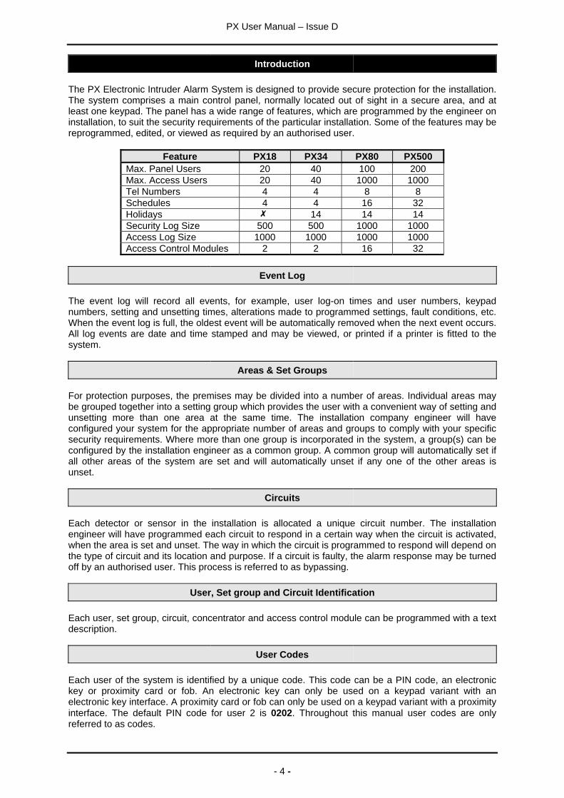
The PX Electronic Intruder Alarm System is designed to provide secure protection for the installation.The system comprises a main control panel, normally located out of sight in a secure area, and atleast one keypad. The panel has a wide range of features, which are programmed by the engineer oninstallation, to suit the security requirements of the particular installation. Some of the features may bereprogrammed, edited, or viewed as required by an authorised user.
Feature PX18 PX34 PX80 PX500Max. Panel Users 20 40 100 200Max. Access Users 20 40 1000 1000Tel Numbers 4 4 8 8Schedules 4 4 16 32Holidays 14 14 14Security Log Size 500 500 1000 1000Access Log Size 1000 1000 1000 1000Access Control Modules 2 2 16 32
Event Log
The event log will record all events, for example, user log-on times and user numbers, keypadnumbers, setting and unsetting times, alterations made to programmed settings, fault conditions, etc.When the event log is full, the oldest event will be automatically removed when the next event occurs.All log events are date and time stamped and may be viewed, or printed if a printer is fitted to thesystem.
Areas & Set Groups
For protection purposes, the premises may be divided into a number of areas. Individual areas maybe grouped together into a setting group which provides the user with a convenient way of setting andunsetting more than one area at the same time. The installation company engineer will haveconfigured your system for the appropriate number of areas and groups to comply with your specificsecurity requirements. Where more than one group is incorporated in the system, a group(s) can beconfigured by the installation engineer as a common group. A common group will automatically set ifall other areas of the system are set and will automatically unset if any one of the other areas isunset.
Circuits
Each detector or sensor in the installation is allocated a unique circuit number. The installationengineer will have programmed each circuit to respond in a certain way when the circuit is activated,when the area is set and unset. The way in which the circuit is programmed to respond will depend onthe type of circuit and its location and purpose. If a circuit is faulty, the alarm response may be turnedoff by an authorised user. This process is referred to as bypassing.
User, Set group and Circuit Identification
Each user, set group, circuit, concentrator and access control module can be programmed with a textdescription.
User Codes
Each user of the system is identified by a unique code. This code can be a PIN code, an electronickey or proximity card or fob. An electronic key can only be used on a keypad variant with anelectronic key interface. A proximity card or fob can only be used on a keypad variant with a proximityinterface. The default PIN code for user 2 is 0202. Throughout this manual user codes are onlyreferred to as codes.
PX User Manual – Issue D
- 5 -
Operator Controls and Displays
System Keypads
2 x 16 characterLCD backlit display
Mains indicator
Optional electronickey socket
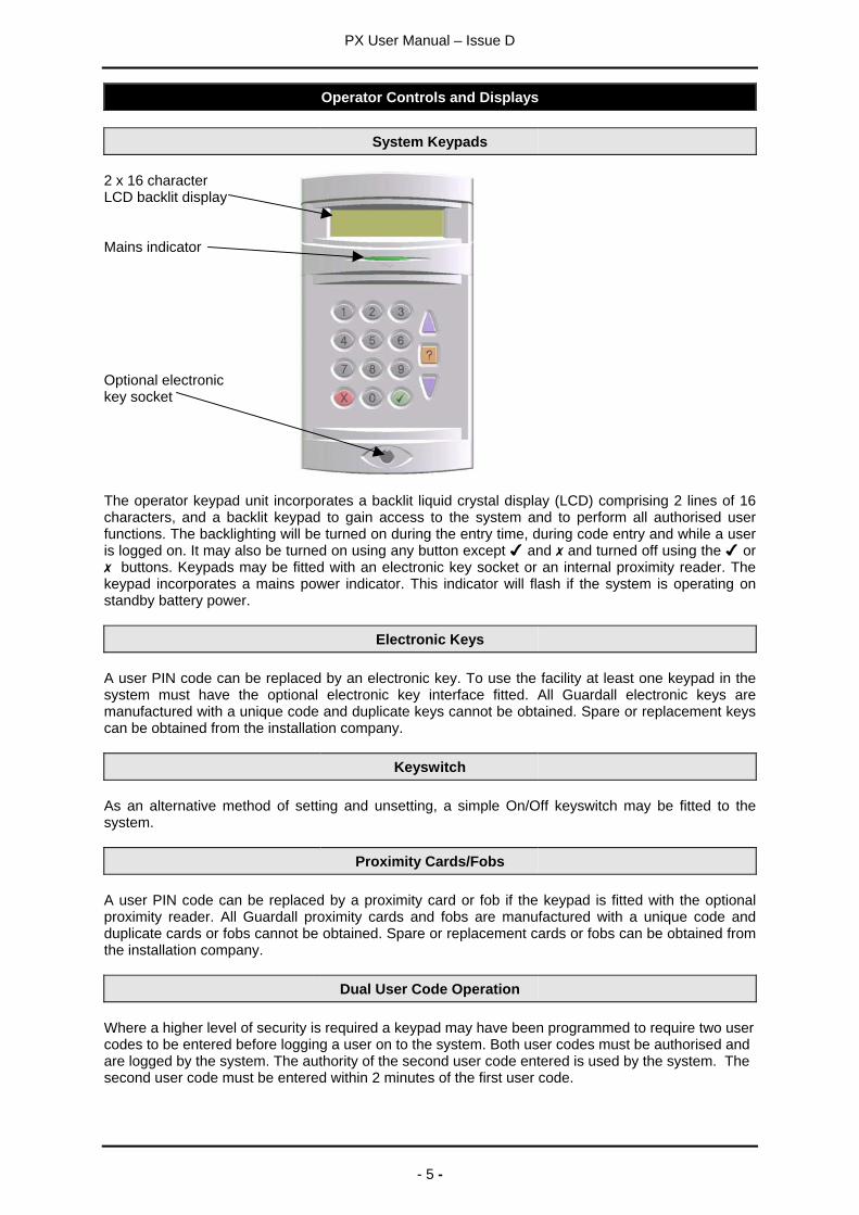
The operator keypad unit incorporates a backlit liquid crystal display (LCD) comprising 2 lines of 16characters, and a backlit keypad to gain access to the system and to perform all authorised userfunctions. The backlighting will be turned on during the entry time, during code entry and while a useris logged on. It may also be turned on using any button except and and turned off using the or
buttons. Keypads may be fitted with an electronic key socket or an internal proximity reader. Thekeypad incorporates a mains power indicator. This indicator will flash if the system is operating onstandby battery power.
Electronic Keys
A user PIN code can be replaced by an electronic key. To use the facility at least one keypad in thesystem must have the optional electronic key interface fitted. All Guardall electronic keys aremanufactured with a unique code and duplicate keys cannot be obtained. Spare or replacement keyscan be obtained from the installation company.
Keyswitch
As an alternative method of setting and unsetting, a simple On/Off keyswitch may be fitted to thesystem.
Proximity Cards/Fobs
A user PIN code can be replaced by a proximity card or fob if the keypad is fitted with the optionalproximity reader. All Guardall proximity cards and fobs are manufactured with a unique code andduplicate cards or fobs cannot be obtained. Spare or replacement cards or fobs can be obtained fromthe installation company.
Dual User Code Operation
Where a higher level of security is required a keypad may have been programmed to require two usercodes to be entered before logging a user on to the system. Both user codes must be authorised andare logged by the system. The authority of the second user code entered is used by the system. Thesecond user code must be entered within 2 minutes of the first user code.
PX User Manual – Issue D
- 6 -
Using the System
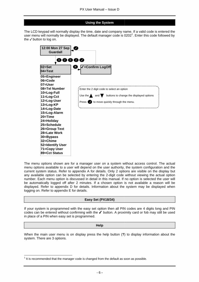
The LCD keypad will normally display the time, date and company name. If a valid code is entered theuser menu will normally be displayed. The default manager code is 02021. Enter this code followed bythe button to log on.
12:00 Mon 27 SepGuardall
0 2 0 2
05=Engineer06=Code07=User08=Tel Number10=Log-Full11=Log-Cct12=Log-User13=Log-KP14=Log-Date15=Log-Alarm20=Time24=Holiday25=Schedule26=Group Text28=Late Work30=Bypass32=Chime52=Identify User71=Copy User89=Cct Status
=Confirm LogOff02=Set04=Test
Enter the 2 digit code to select an option
Use the and buttons to change the displayed options
Press to move quickly through the menu.
The menu options shown are for a manager user on a system without access control. The actualmenu options available to a user will depend on the user authority, the system configuration and thecurrent system status. Refer to appendix A for details. Only 2 options are visible on the display butany available option can be selected by entering the 2-digit code without viewing the actual optionnumber. Each menu option is discussed in detail in this manual. If no option is selected the user willbe automatically logged off after 2 minutes. If a chosen option is not available a reason will bedisplayed. Refer to appendix D for details. Information about the system may be displayed whenlogging on. Refer to appendix E for details.
Easy Set (PX18/34)
If your system is programmed with the easy set option then all PIN codes are 4 digits long and PINcodes can be entered without confirming with the button. A proximity card or fob may still be usedin place of a PIN when easy set is programmed.
Help
When the main user menu is on display press the help button (?) to display information about thesystem. There are 3 options.
1 It is recommended that the manager code is changed from the default as soon as possible.
PX User Manual – Issue D
- 7 -
Option DescriptionRemote Service Select to connect to a remote service operator. Your alarm company may not
support this feature.Contract The customer contract number is a 6-digit number programmed by the
installation engineer that uniquely identifies your system.Product Info The product info option displays the control panel order code and firmware
version number and, if fitted the SmartDial version number.
An authorised user can change some of the system parameters. When changing an item the helpbutton can be used to display the allowed values.
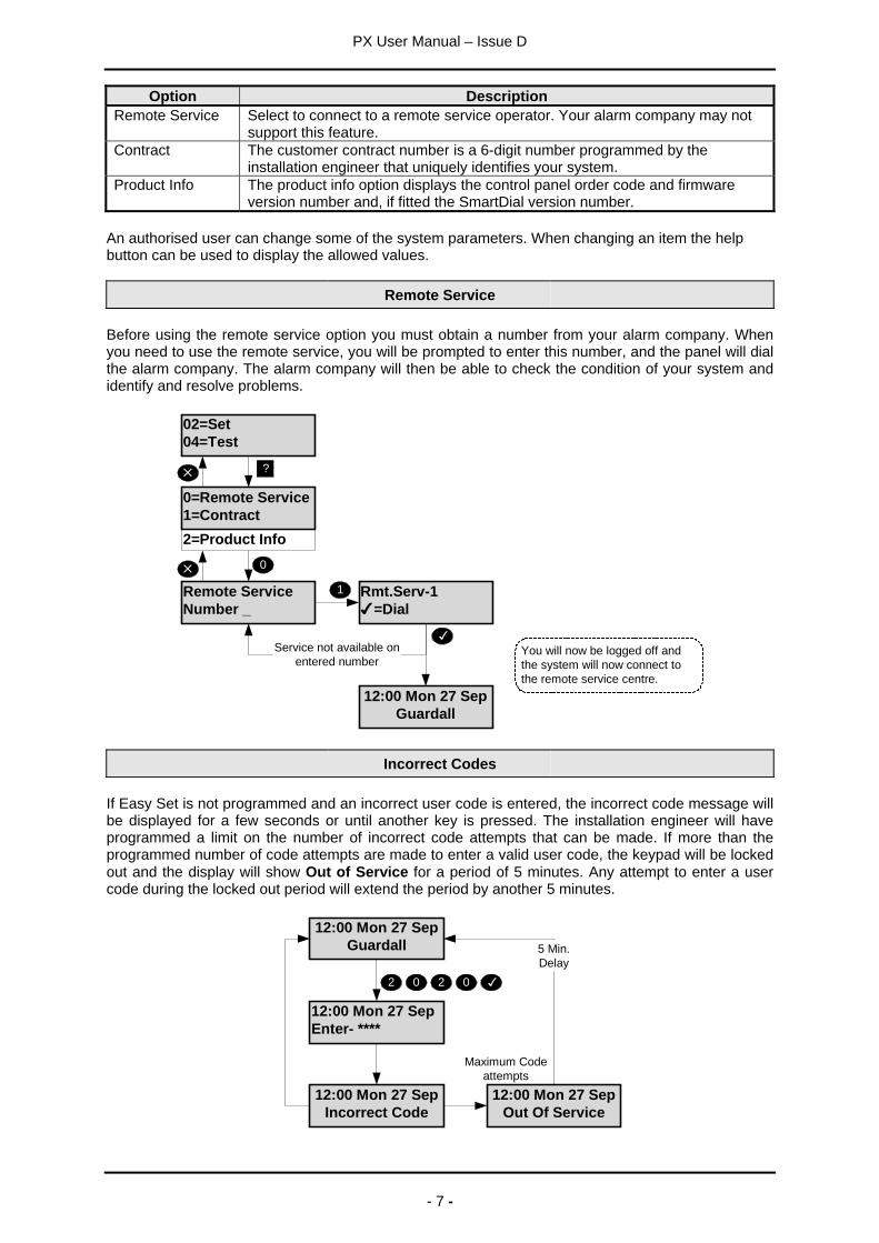
Remote Service
Before using the remote service option you must obtain a number from your alarm company. Whenyou need to use the remote service, you will be prompted to enter this number, and the panel will dialthe alarm company. The alarm company will then be able to check the condition of your system andidentify and resolve problems.
02=Set04=Test
?
Remote ServiceNumber _
0
Rmt.Serv-1=Dial
12:00 Mon 27 SepGuardall
Service not available onentered number
2=Product Info
0=Remote Service1=Contract
1
You will now be logged off andthe system will now connect tothe remote service centre.
Incorrect Codes
If Easy Set is not programmed and an incorrect user code is entered, the incorrect code message willbe displayed for a few seconds or until another key is pressed. The installation engineer will haveprogrammed a limit on the number of incorrect code attempts that can be made. If more than theprogrammed number of code attempts are made to enter a valid user code, the keypad will be lockedout and the display will show Out of Service for a period of 5 minutes. Any attempt to enter a usercode during the locked out period will extend the period by another 5 minutes.
12:00 Mon 27 SepGuardall
12:00 Mon 27 SepEnter- ****
02 0 2
12:00 Mon 27 SepIncorrect Code
12:00 Mon 27 SepOut Of Service
5 Min.Delay
Maximum Codeattempts
PX User Manual – Issue D
- 8 -
Set Code-02
The system can be partitioned into a number of parts called set groups, each of which can beindividually set. The programmed user authority level must allow setting and the programmed userarea access will determine which set groups are available to a user.
Setting can be started by:
1. A user request on a keypad2. A user activating a keyswitch3. Automatically by a timer schedule4. Remotely from a PC using the Guardall GuardStation software5. A user request on an ACM Proximity Reader.
Setting modes include:
1. Instant, where setting is completed immediately2. Timed, where setting is completed at the end of the programmed exit time3. Exit point, where setting is completed by opening and closing the final exit circuit4. Push button, where setting is completed by pushing the external PB circuits after opening and
closing the final exit circuit
Your installation engineer should advise which of the above options have been programmed on yoursystem.
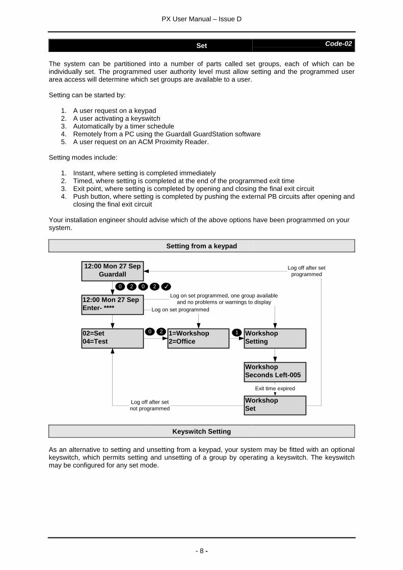
Setting from a keypad
02=Set04=Test
WorkshopSeconds Left-005
1=Workshop2=Office
10 2
12:00 Mon 27 SepGuardall
WorkshopSetting
WorkshopSet
12:00 Mon 27 SepEnter- ****
0 2 0 2
Log on set programmed
Log on set programmed, one group availableand no problems or warnings to display
Exit time expired
Log off after setnot programmed
Log off after setprogrammed
Keyswitch Setting
As an alternative to setting and unsetting from a keypad, your system may be fitted with an optionalkeyswitch, which permits setting and unsetting of a group by operating a keyswitch. The keyswitchmay be configured for any set mode.
PX User Manual – Issue D
- 9 -
Automatic Setting
The system may have been programmed by the installation engineer to automatically set all or partsof the system according to a pre-programmed schedule. The schedule will have been programmed totake into account the normal closing time, non-working days and holidays. The schedule may beconfigured for any set mode.
Aborting The Setting Procedure
The setting procedure can be aborted at any time during the exit time by pressing on the keypadthat was used to start setting, logging on to any other keypad or turning a keyswitch to the unsetposition.
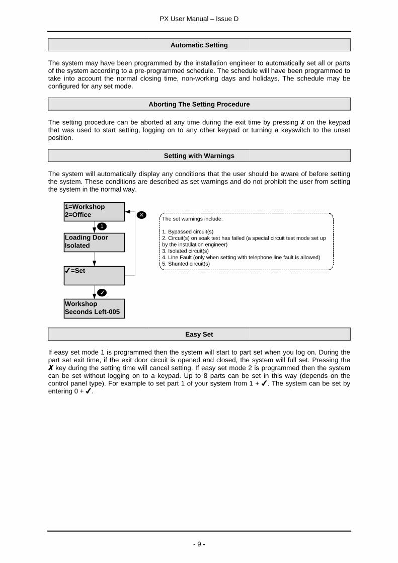
Setting with Warnings
The system will automatically display any conditions that the user should be aware of before settingthe system. These conditions are described as set warnings and do not prohibit the user from settingthe system in the normal way.
WorkshopSeconds Left-005
1=Workshop2=Office
1
Loading DoorIsolated
=Set
The set warnings include:
1. Bypassed circuit(s)2. Circuit(s) on soak test has failed (a special circuit test mode set upby the installation engineer)3. Isolated circuit(s)4. Line Fault (only when setting with telephone line fault is allowed)5. Shunted circuit(s)
Easy Set
If easy set mode 1 is programmed then the system will start to part set when you log on. During thepart set exit time, if the exit door circuit is opened and closed, the system will full set. Pressing the
key during the setting time will cancel setting. If easy set mode 2 is programmed then the systemcan be set without logging on to a keypad. Up to 8 parts can be set in this way (depends on thecontrol panel type). For example to set part 1 of your system from 1 + . The system can be set byentering 0 + .
PX User Manual – Issue D
- 10 -
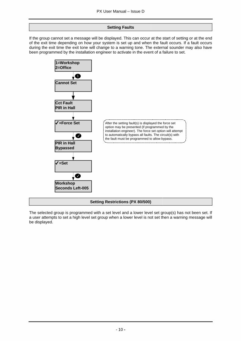
Setting Faults
If the group cannot set a message will be displayed. This can occur at the start of setting or at the endof the exit time depending on how your system is set up and when the fault occurs. If a fault occursduring the exit time the exit tone will change to a warning tone. The external sounder may also havebeen programmed by the installation engineer to activate in the event of a failure to set.
WorkshopSeconds Left-005
1=Workshop2=Office
1
Cannot Set
Cct FaultPIR in Hall
=Force Set After the setting fault(s) is displayed the force setoption may be presented (if programmed by theinstallation engineer). The force set option will attemptto automatically bypass all faults. The circuit(s) withthe fault must be programmed to allow bypass.
PIR in HallBypassed
=Set
Setting Restrictions (PX 80/500)
The selected group is programmed with a set level and a lower level set group(s) has not been set. Ifa user attempts to set a high level set group when a lower level is not set then a warning message willbe displayed.
PX User Manual – Issue D
- 11 -
Unset Code-01
The system will have been partitioned by the installation engineer into a number of set groups. Theuser authority will determine the choice of groups, which can be unset. There are several methods ofunsetting available to the user which are discussed in the following section.
Unsetting can be started by:
1. A user request on a keypad2. A user activating a keyswitch3. Automatically by a timer schedule4. Remotely from a PC using the Guardall GuardStation software5. A user request on an ACM Proximity Reader.
Your installation engineer should advise which of the above options have been programmed on yoursystem.
Unsetting Methods
If a set group incorporates an entry route in the unsetting procedure then opening a final entry door tothe area will start a pre-programmed entry timer. The user must proceed directly to the keypad orkeyswitch via a pre-determined entry route and unset the group as described. If the group is not unsetbefore the entry time has expired a warning period, equivalent to 50% of the programmed entry time,will be allowed. This is to warn the user that an alarm condition will occur if the group is not unset bythe end of the warning period. If the group is not unset by the time that the total entry time andwarning time has expired, an alarm condition will be initiated. To comply with the requirements ofDD243 (2002), during the entry time, all alarms in the unsetting area(s) are ignored.
Unsetting from a keypad
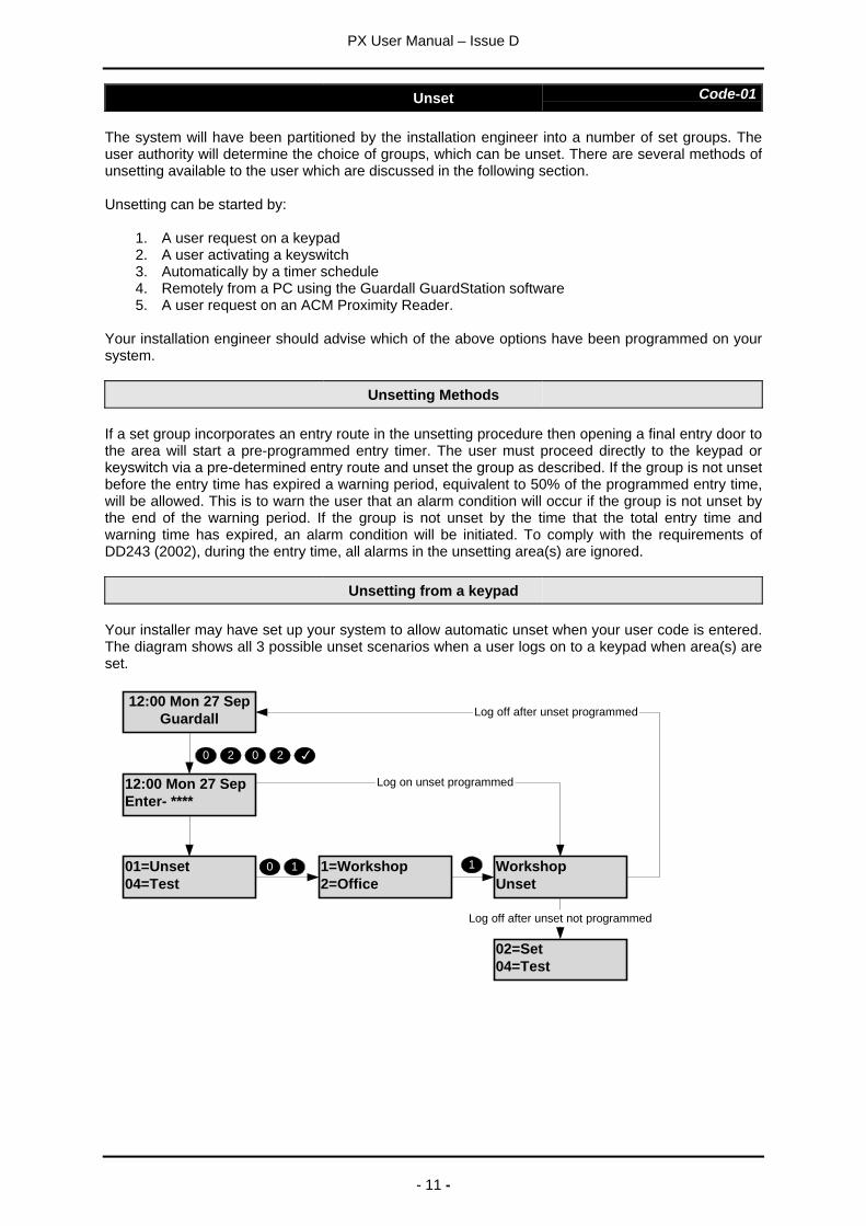
Your installer may have set up your system to allow automatic unset when your user code is entered.The diagram shows all 3 possible unset scenarios when a user logs on to a keypad when area(s) areset.
01=Unset04=Test
1=Workshop2=Office
10
12:00 Mon 27 SepGuardall
WorkshopUnset
12:00 Mon 27 SepEnter- ****
0 2 0 2
Log on unset programmed
1
02=Set04=Test
Log off after unset programmed
Log off after unset not programmed
PX User Manual – Issue D
- 12 -
Unsetting from a keyswitch
To unset an area from a keyswitch, turn the keyswitch to the unset position. The area under thecontrol of the keyswitch will immediately unset.
Automatic Unsetting
The system may have been programmed by the installation engineer to automatically unset all orparts of the system according to a pre-programmed schedule. The schedule will have beenprogrammed to take into account the normal opening time, non-working days and holidays.
Unsetting Warnings
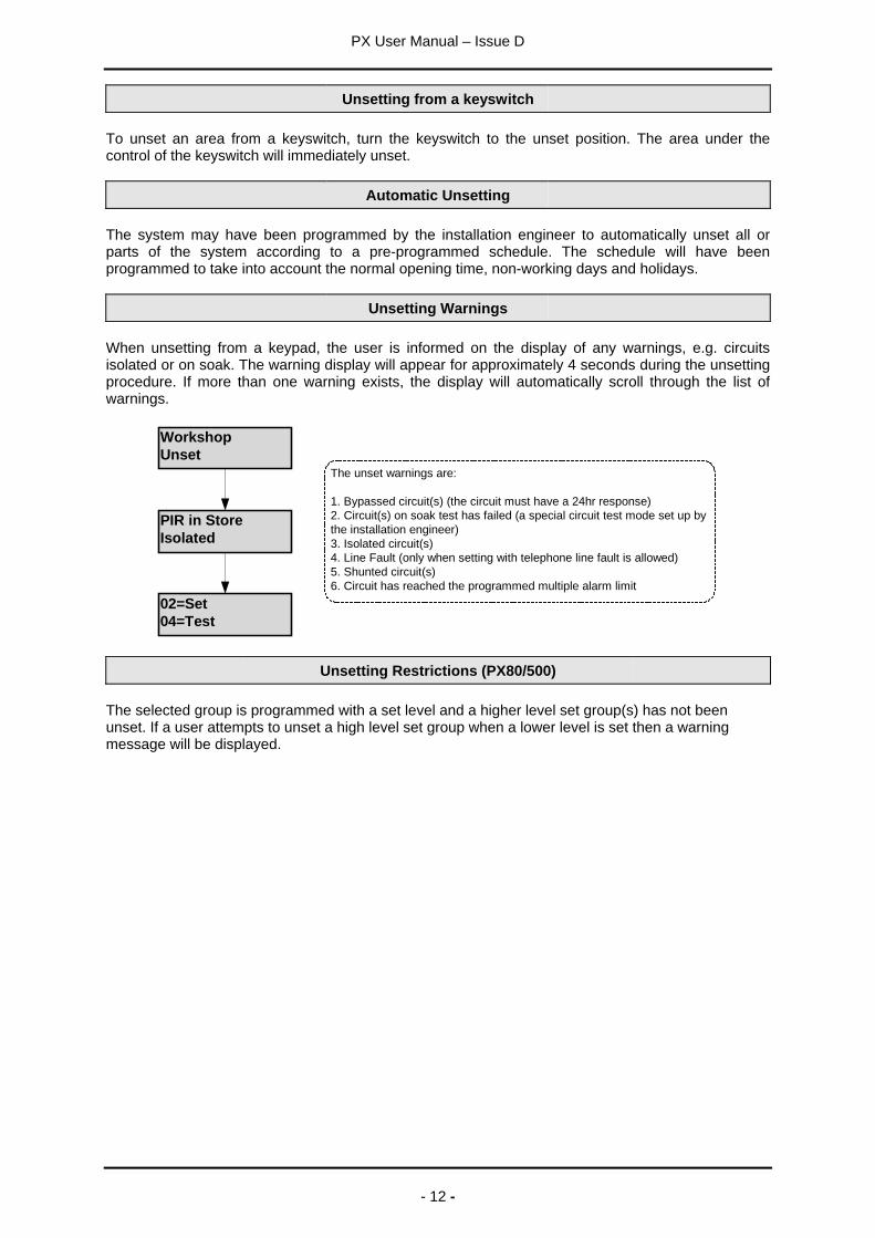
When unsetting from a keypad, the user is informed on the display of any warnings, e.g. circuitsisolated or on soak. The warning display will appear for approximately 4 seconds during the unsettingprocedure. If more than one warning exists, the display will automatically scroll through the list ofwarnings.
WorkshopUnset
02=Set04=Test
PIR in StoreIsolated
The unset warnings are:
1. Bypassed circuit(s) (the circuit must have a 24hr response)2. Circuit(s) on soak test has failed (a special circuit test mode set up bythe installation engineer)3. Isolated circuit(s)4. Line Fault (only when setting with telephone line fault is allowed)5. Shunted circuit(s)6. Circuit has reached the programmed multiple alarm limit
Unsetting Restrictions (PX80/500)
The selected group is programmed with a set level and a higher level set group(s) has not beenunset. If a user attempts to unset a high level set group when a lower level is set then a warningmessage will be displayed.

PX User Manual – Issue D
- 13 -
Reset Code-03
The resetting method programmed by the alarm company engineer for each area and the system willdepend on the particular security requirements of the area or system. There are 3 types of reset:
1. Customer reset, where the customer can reset any alarm2. Engineer reset, where the alarm company engineer must reset all alarms3. Managed reset, where the customer can reset an alarm after reporting the event to the alarm
company
WorkshopUnset
AlarmPIR in Office
=Reset
02=Set04=Test
01313333802Code:123456
If your system is programmed for engineer reset atelephone number and code will be displayed. Call thisnumber and quote your code. if your system isconfigured for managed reset you will be given a codeto reset your system. This code can only be usedonce.
If an engineer reset is required, it will not be possibleto set the system.
Alarm cannot be reset
Managed Reset
If the system is programmed for managed reset and an engineer reset is required contact the alarminstallation company. You will be issued with a special 6-digit PIN code. This PIN code can be usedonly once to reset the system. Enter the PIN to clear the engineer reset condition.
12:00 Mon 27 SepGuardall
12:00 Mon 27 SepEnter- *****
Reset OK
reset code +
PX User Manual – Issue D
- 14 -
Test Code-04
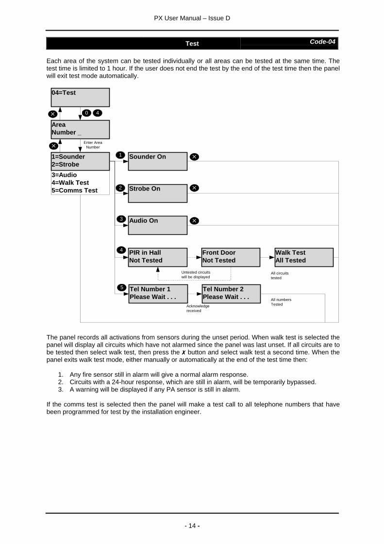
Each area of the system can be tested individually or all areas can be tested at the same time. Thetest time is limited to 1 hour. If the user does not end the test by the end of the test time then the panelwill exit test mode automatically.
04=Test
AreaNumber _
4
Sounder On1
Enter AreaNumber
Audio On
Strobe On2
3
PIR in HallNot Tested
Front DoorNot Tested
Walk TestAll Tested
Untested circuitswill be displayed
Tel Number 1Please Wait . . .
Tel Number 2Please Wait . . .
Acknowledgereceived
5
All numbersTested
0
3=Audio4=Walk Test5=Comms Test
1=Sounder2=Strobe
4
All circuitstested
The panel records all activations from sensors during the unset period. When walk test is selected thepanel will display all circuits which have not alarmed since the panel was last unset. If all circuits are tobe tested then select walk test, then press the button and select walk test a second time. When thepanel exits walk test mode, either manually or automatically at the end of the test time then:
1. Any fire sensor still in alarm will give a normal alarm response.2. Circuits with a 24-hour response, which are still in alarm, will be temporarily bypassed.3. A warning will be displayed if any PA sensor is still in alarm.
If the comms test is selected then the panel will make a test call to all telephone numbers that havebeen programmed for test by the installation engineer.
PX User Manual – Issue D
- 15 -
Engineer Code-05
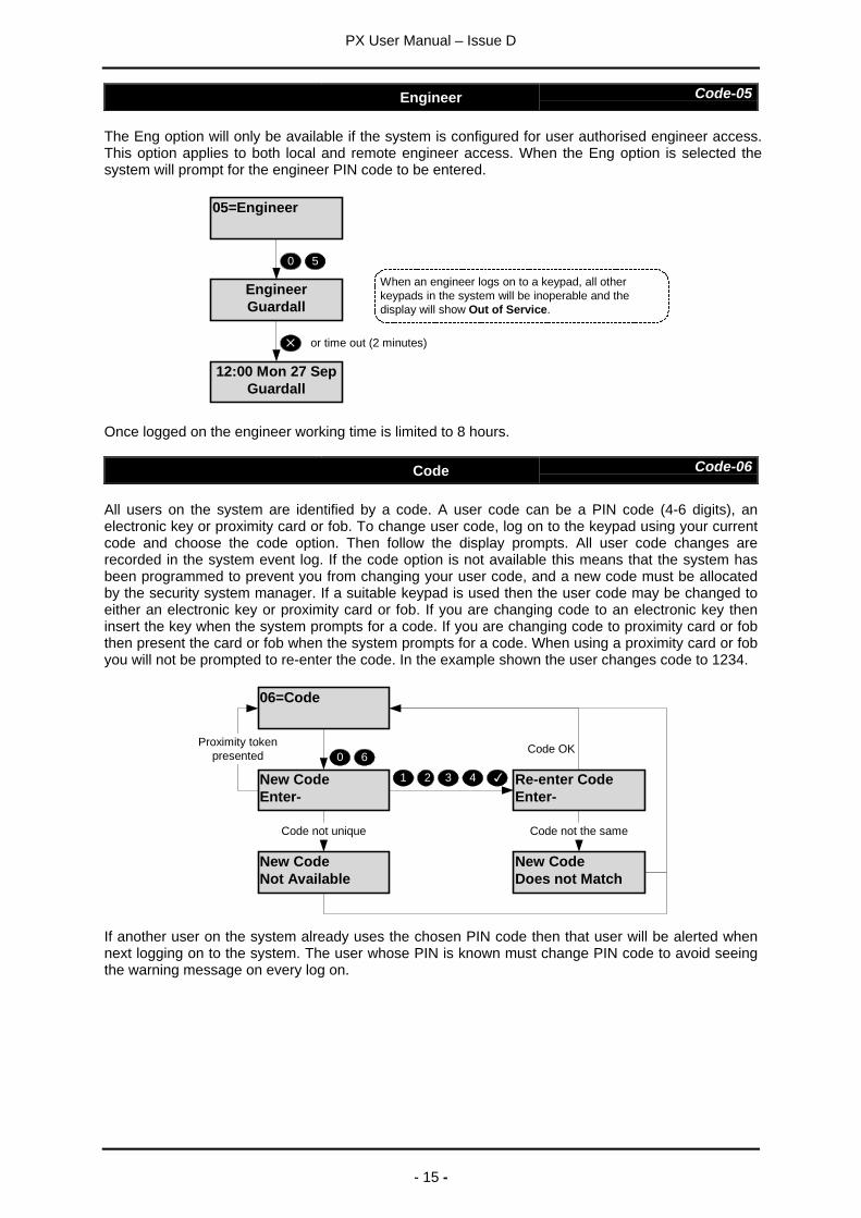
The Eng option will only be available if the system is configured for user authorised engineer access.This option applies to both local and remote engineer access. When the Eng option is selected thesystem will prompt for the engineer PIN code to be entered.
05=Engineer
EngineerGuardall
12:00 Mon 27 SepGuardall
0 5
When an engineer logs on to a keypad, all otherkeypads in the system will be inoperable and thedisplay will show Out of Service.
or time out (2 minutes)
Once logged on the engineer working time is limited to 8 hours.
Code Code-06
All users on the system are identified by a code. A user code can be a PIN code (4-6 digits), anelectronic key or proximity card or fob. To change user code, log on to the keypad using your currentcode and choose the code option. Then follow the display prompts. All user code changes arerecorded in the system event log. If the code option is not available this means that the system hasbeen programmed to prevent you from changing your user code, and a new code must be allocatedby the security system manager. If a suitable keypad is used then the user code may be changed toeither an electronic key or proximity card or fob. If you are changing code to an electronic key theninsert the key when the system prompts for a code. If you are changing code to proximity card or fobthen present the card or fob when the system prompts for a code. When using a proximity card or fobyou will not be prompted to re-enter the code. In the example shown the user changes code to 1234.
06=Code
New CodeNot Available
New CodeEnter-
Re-enter CodeEnter-
New CodeDoes not Match
21 3 4
0 6
Code not unique Code not the same
Proximity tokenpresented Code OK
If another user on the system already uses the chosen PIN code then that user will be alerted whennext logging on to the system. The user whose PIN is known must change PIN code to avoid seeingthe warning message on every log on.
PX User Manual – Issue D
- 16 -
User Code-07
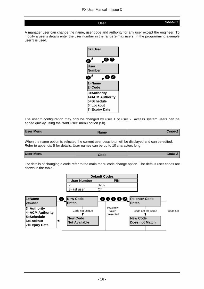
A manager user can change the name, user code and authority for any user except the engineer. Tomodify a user’s details enter the user number in the range 2-max users. In the programming exampleuser 3 is used.
07=User
UserNumber ____
0 7
3=Authority4=ACM Authority5=Schedule6=Lockout7=Expiry Date
1=Name2=Code
3
The user 2 configuration may only be changed by user 1 or user 2. Access system users can beadded quickly using the “Add User” menu option (50).
User Menu Name Code-1
When the name option is selected the current user descriptor will be displayed and can be edited.Refer to appendix B for details. User names can be up to 10 characters long.
User Menu Code Code-2
For details of changing a code refer to the main menu code change option. The default user codes areshown in the table.
Default CodesUser Number PIN
2 02023-last user Off
New CodeNot Available
New CodeEnter-
Re-enter CodeEnter-
New CodeDoes not Match
21 3 4
Code not unique Code not the same3=Authority4=ACM Authority5=Schedule6=Lockout7=Expiry Date
1=Name2=Code
2
Proximitytoken
presentedCode OK
PX User Manual – Issue D
- 17 -
User Menu Authority Code-3
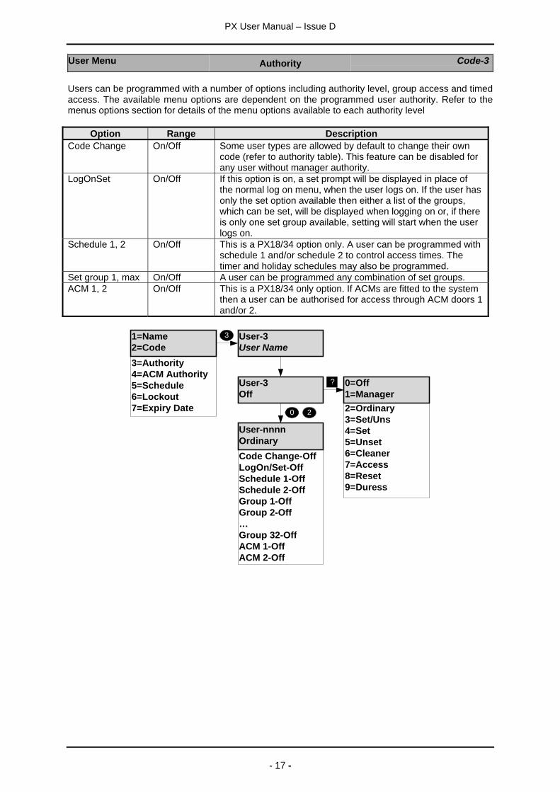
Users can be programmed with a number of options including authority level, group access and timedaccess. The available menu options are dependent on the programmed user authority. Refer to themenus options section for details of the menu options available to each authority level
Option Range DescriptionCode Change On/Off Some user types are allowed by default to change their own
code (refer to authority table). This feature can be disabled forany user without manager authority.
LogOnSet On/Off If this option is on, a set prompt will be displayed in place ofthe normal log on menu, when the user logs on. If the user hasonly the set option available then either a list of the groups,which can be set, will be displayed when logging on or, if thereis only one set group available, setting will start when the userlogs on.
Schedule 1, 2 On/Off This is a PX18/34 option only. A user can be programmed withschedule 1 and/or schedule 2 to control access times. Thetimer and holiday schedules may also be programmed.
Set group 1, max On/Off A user can be programmed any combination of set groups.ACM 1, 2 On/Off This is a PX18/34 only option. If ACMs are fitted to the system
then a user can be authorised for access through ACM doors 1and/or 2.
User-3User Name
User-3Off
?
0 2
3
2=Ordinary3=Set/Uns4=Set5=Unset6=Cleaner7=Access8=Reset9=Duress
3=Authority4=ACM Authority5=Schedule6=Lockout7=Expiry Date
Code Change-OffLogOn/Set-OffSchedule 1-OffSchedule 2-OffGroup 1-OffGroup 2-Off…Group 32-OffACM 1-OffACM 2-Off
1=Name2=Code
User-nnnnOrdinary
0=Off1=Manager
PX User Manual – Issue D
- 18 -
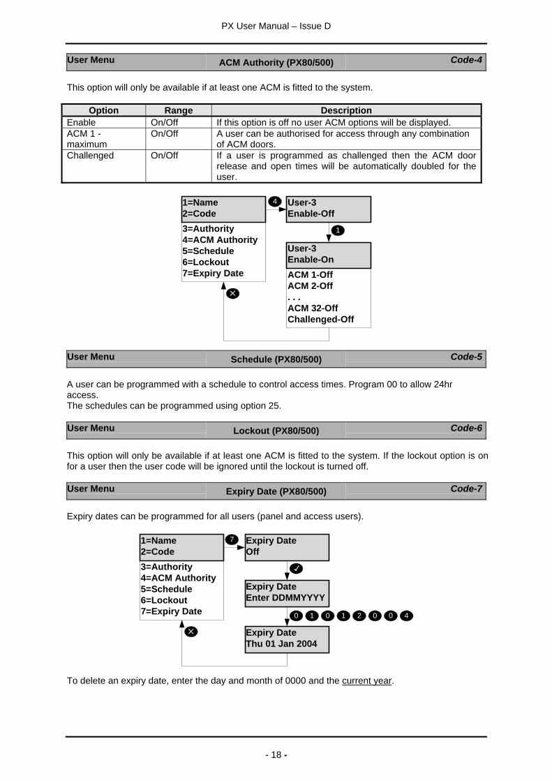
User Menu ACM Authority (PX80/500) Code-4
This option will only be available if at least one ACM is fitted to the system.
Option Range DescriptionEnable On/Off If this option is off no user ACM options will be displayed.ACM 1 -maximum
On/Off A user can be authorised for access through any combinationof ACM doors.
Challenged On/Off If a user is programmed as challenged then the ACM doorrelease and open times will be automatically doubled for theuser.
3=Authority4=ACM Authority5=Schedule6=Lockout7=Expiry Date ACM 1-Off
ACM 2-Off. . .ACM 32-OffChallenged-Off
1=Name2=Code
User-3Enable-Off
4
User-3Enable-On
1
User Menu Schedule (PX80/500) Code-5
A user can be programmed with a schedule to control access times. Program 00 to allow 24hraccess.The schedules can be programmed using option 25.
User Menu Lockout (PX80/500) Code-6
This option will only be available if at least one ACM is fitted to the system. If the lockout option is onfor a user then the user code will be ignored until the lockout is turned off.
User Menu Expiry Date (PX80/500) Code-7
Expiry dates can be programmed for all users (panel and access users).
Expiry DateOff
Expiry DateEnter DDMMYYYY
3=Authority4=ACM Authority5=Schedule6=Lockout7=Expiry Date
1=Name2=Code
7
Expiry DateThu 01 Jan 2004
0 1 0 1 2 0 0 4
To delete an expiry date, enter the day and month of 0000 and the current year.
PX User Manual – Issue D
- 19 -
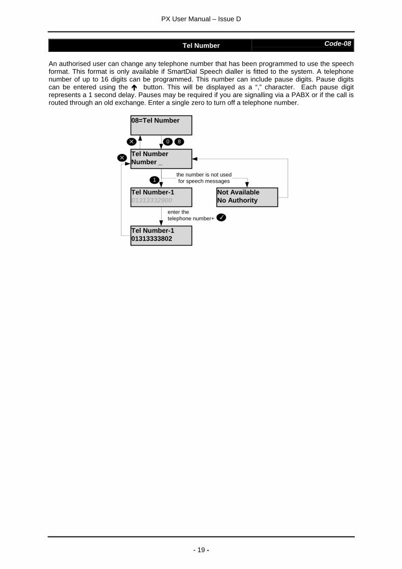
Tel Number Code-08
An authorised user can change any telephone number that has been programmed to use the speechformat. This format is only available if SmartDial Speech dialler is fitted to the system. A telephonenumber of up to 16 digits can be programmed. This number can include pause digits. Pause digitscan be entered using the button. This will be displayed as a “,” character. Each pause digitrepresents a 1 second delay. Pauses may be required if you are signalling via a PABX or if the call isrouted through an old exchange. Enter a single zero to turn off a telephone number.
Tel Number-101313332900
08=Tel Number
Tel NumberNumber _
Not AvailableNo Authority
Tel Number-101313333802
the number is not usedfor speech messages
0
1
8
enter thetelephone number+
PX User Manual – Issue D
- 20 -
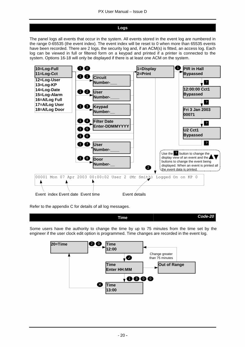
Logs
The panel logs all events that occur in the system. All events stored in the event log are numbered inthe range 0-65535 (the event index). The event index will be reset to 0 when more than 65535 eventshave been recorded. There are 2 logs, the security log and, if an ACM(s) is fitted, an access log. Eachlog can be viewed in full or filtered form on a keypad and printed if a printer is connected to thesystem. Options 16-18 will only be displayed if there is at least one ACM on the system.
CircuitNumber-___
UserNumber-____
KeypadNumber-__
Filter DateEnter-DDMMYYYY
UserNumber-____
DoorNumber-__
1=Display2=Print
12:00:00 Cct1Bypassed
Fri 3 Jan 200300071
U2 Cct1Bypassed
PIR in HallBypassed
2
1
0
1
1
1 2
1 3
1 4
1
7
1
8
1
6
1
?
?
?
?12=Log-User13=Log-KP14=Log-Date15=Log-Alarm16=A/Log Full17=A/Log User18=A/Log Door
10=Log-Full11=Log-Cct
1 5
00001 Mon 07 Apr 2003 00:00:02 User 2 (Mr Smith) Logged On on KP 0
Event index Event date Event time Event details
Use the button to change thedisplay view of an event and thebuttons to change the event beingdisplayed. When an event is printed allthe event data is printed.
?
Refer to the appendix C for details of all log messages.
Time Code-20
Some users have the authority to change the time by up to 75 minutes from the time set by theengineer if the user clock edit option is programmed. Time changes are recorded in the event log.
TimeEnter HH:MM
20=Time Time12:00
02
Out of Range
Time13:00
1 3 0 0
Change greaterthan 75 minutes
PX User Manual – Issue D
- 21 -
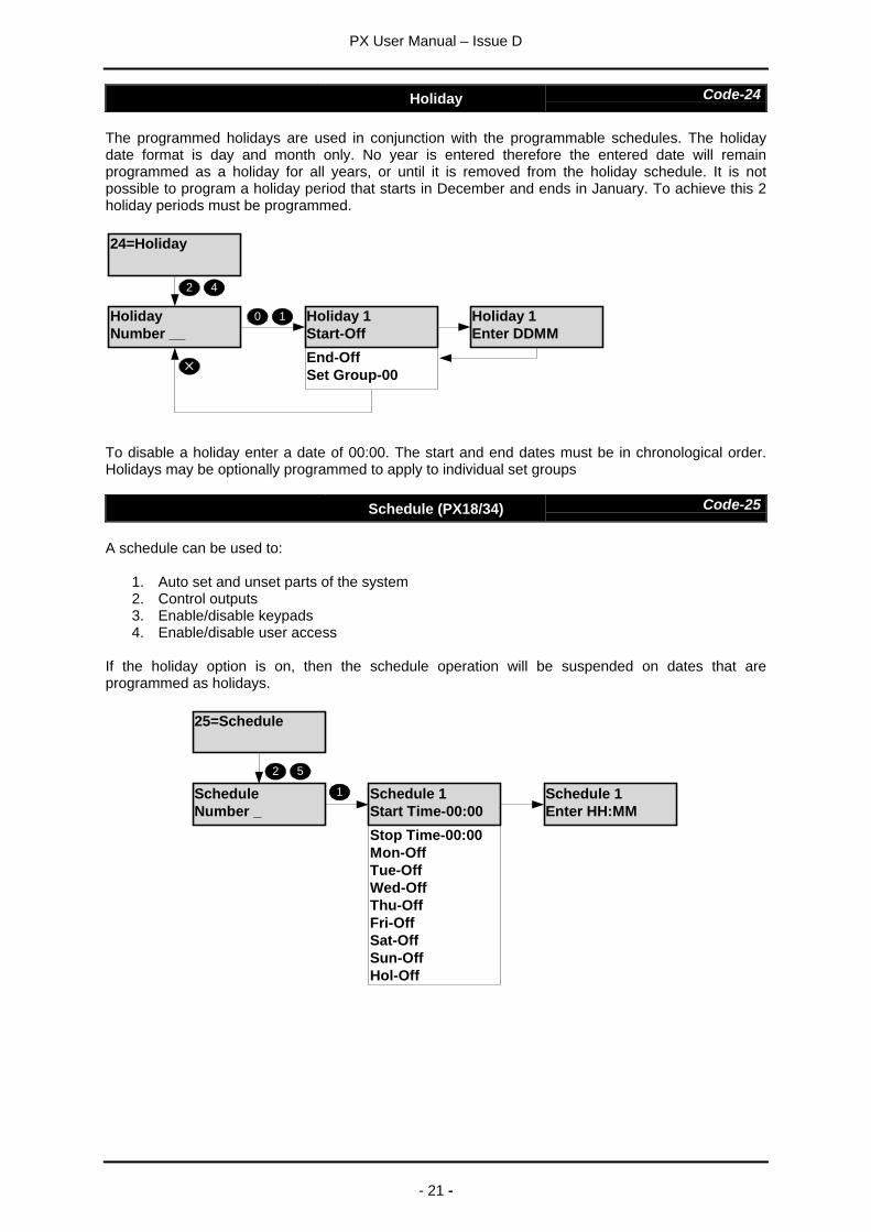
Holiday Code-24
The programmed holidays are used in conjunction with the programmable schedules. The holidaydate format is day and month only. No year is entered therefore the entered date will remainprogrammed as a holiday for all years, or until it is removed from the holiday schedule. It is notpossible to program a holiday period that starts in December and ends in January. To achieve this 2holiday periods must be programmed.
24=Holiday
HolidayNumber __
Holiday 1Enter DDMM
2 4
10
End-OffSet Group-00
Holiday 1Start-Off
To disable a holiday enter a date of 00:00. The start and end dates must be in chronological order.Holidays may be optionally programmed to apply to individual set groups
Schedule (PX18/34) Code-25
A schedule can be used to:
1. Auto set and unset parts of the system2. Control outputs3. Enable/disable keypads4. Enable/disable user access
If the holiday option is on, then the schedule operation will be suspended on dates that areprogrammed as holidays.
25=Schedule
ScheduleNumber _
2
1
5
Schedule 1Enter HH:MM
Stop Time-00:00Mon-OffTue-OffWed-OffThu-OffFri-OffSat-OffSun-OffHol-Off
Schedule 1Start Time-00:00
PX User Manual – Issue D
- 22 -
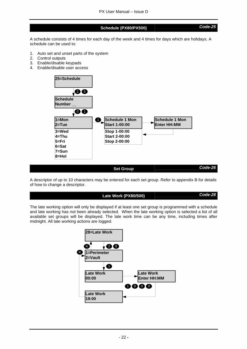
Schedule (PX80/PX500) Code-25
A schedule consists of 4 times for each day of the week and 4 times for days which are holidays. Aschedule can be used to:
1. Auto set and unset parts of the system2. Control outputs3. Enable/disable keypads4. Enable/disable user access
25=Schedule
ScheduleNumber __
2 5
1 Schedule 1 MonEnter HH:MM
0 1
3=Wed4=Thu5=Fri6=Sat7=Sun8=Hol
Stop 1-00:00Start 2-00:00Stop 2-00:00
Schedule 1 MonStart 1-00:00
1=Mon2=Tue
Set Group Code-26
A descriptor of up to 10 characters may be entered for each set group. Refer to appendix B for detailsof how to change a descriptor.
Late Work (PX80/500) Code-28
The late working option will only be displayed if at least one set group is programmed with a scheduleand late working has not been already selected. When the late working option is selected a list of allavailable set groups will be displayed. The late work time can be any time, including times aftermidnight. All late working actions are logged.
28=Late Work
1=Perimeter2=Vault
Late Work00:00
2 8
1
Late WorkEnter HH:MM
Late Work19:00
1 9 0 0
PX User Manual – Issue D
- 23 -
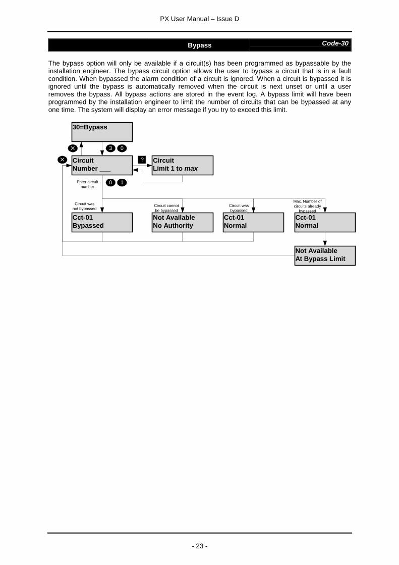
Bypass Code-30
The bypass option will only be available if a circuit(s) has been programmed as bypassable by theinstallation engineer. The bypass circuit option allows the user to bypass a circuit that is in a faultcondition. When bypassed the alarm condition of a circuit is ignored. When a circuit is bypassed it isignored until the bypass is automatically removed when the circuit is next unset or until a userremoves the bypass. All bypass actions are stored in the event log. A bypass limit will have beenprogrammed by the installation engineer to limit the number of circuits that can be bypassed at anyone time. The system will display an error message if you try to exceed this limit.
30=Bypass
CircuitNumber ___
Enter circuitnumber
Cct-01Bypassed
10
CircuitLimit 1 to max
?
Cct-01Normal
Not AvailableNo Authority
Circuit wasnot bypassed
Circuit wasbypassed
Circuit cannotbe bypassed
Cct-01Normal
Not AvailableAt Bypass Limit
Max. Number ofcircuits already
bypassed
3 0
PX User Manual – Issue D
- 24 -
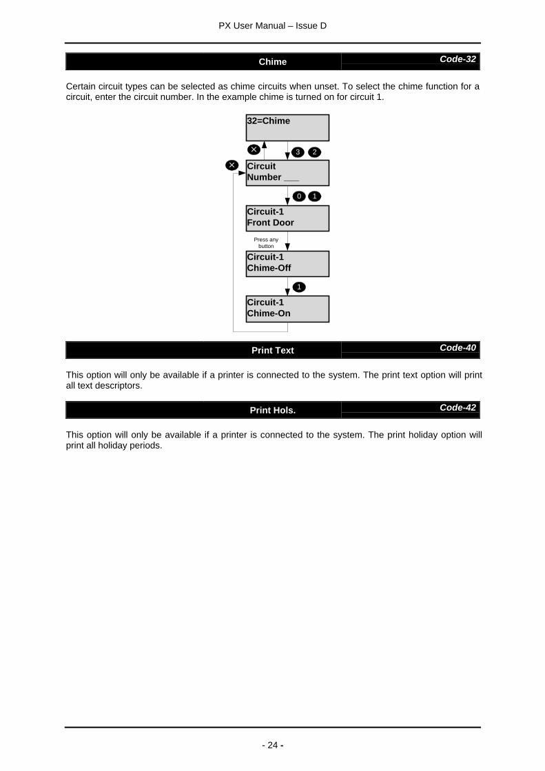
Chime Code-32
Certain circuit types can be selected as chime circuits when unset. To select the chime function for acircuit, enter the circuit number. In the example chime is turned on for circuit 1.
32=Chime
CircuitNumber ___
Circuit-1Front Door
10
3 2
Circuit-1Chime-Off
Press anybutton
Circuit-1Chime-On
1
Print Text Code-40
This option will only be available if a printer is connected to the system. The print text option will printall text descriptors.
Print Hols. Code-42
This option will only be available if a printer is connected to the system. The print holiday option willprint all holiday periods.

PX User Manual – Issue D
- 25 -
Identify User Code-52
This option allows a user to be identified by presenting the card/fob.
52=Identify User
Present Card/Fob
5 2
Code Not Used User 3J Smith
User 3 fob presentedUnused card/fob presented
User 20J Black
User 20 fob presented
Copy User Code-71
71=Copy User
Copy User ______-___
Enter the user to copyhere.
Enter the first and last userin the copy range here.
7 1
To copy a single user, enter the same user number as the first and last.
Copy A/User (PX80/500) Code-73
This option will only be available if at least one ACM is fitted to the system.
73=Copy A/User
Copy A/User ________-____
Enter the user to copyhere.
Enter the first and last userin the copy range here.
7 3
To copy a single user, enter the same user number as the first and last.
PX User Manual – Issue D
- 26 -
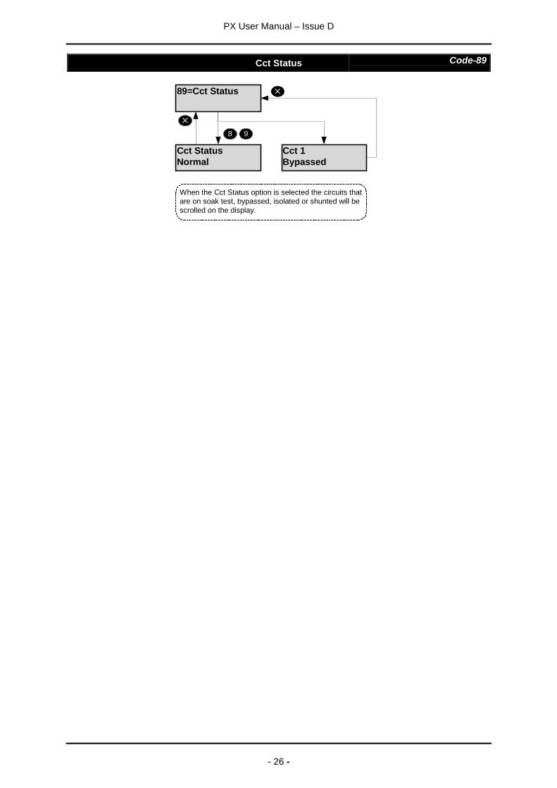
Cct Status Code-89
89=Cct Status
Cct StatusNormal
8 9
Cct 1Bypassed
When the Cct Status option is selected the circuits thatare on soak test, bypassed, isolated or shunted will bescrolled on the display.
PX User Manual – Issue D
- 27 -
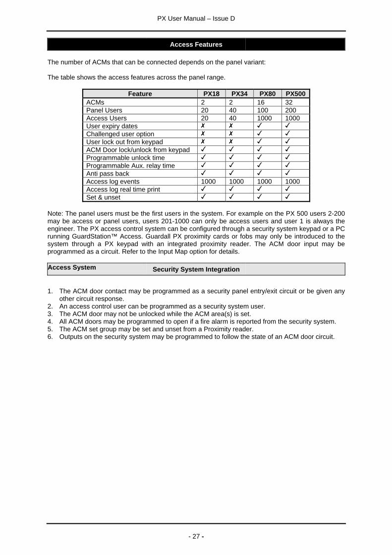
Access Features
The number of ACMs that can be connected depends on the panel variant:
The table shows the access features across the panel range.
Feature PX18 PX34 PX80 PX500ACMs 2 2 16 32Panel Users 20 40 100 200Access Users 20 40 1000 1000User expiry datesChallenged user optionUser lock out from keypadACM Door lock/unlock from keypadProgrammable unlock timeProgrammable Aux. relay timeAnti pass backAccess log events 1000 1000 1000 1000Access log real time printSet & unset
Note: The panel users must be the first users in the system. For example on the PX 500 users 2-200may be access or panel users, users 201-1000 can only be access users and user 1 is always theengineer. The PX access control system can be configured through a security system keypad or a PCrunning GuardStation™ Access. Guardall PX proximity cards or fobs may only be introduced to thesystem through a PX keypad with an integrated proximity reader. The ACM door input may beprogrammed as a circuit. Refer to the Input Map option for details.
Access System Security System Integration
1. The ACM door contact may be programmed as a security panel entry/exit circuit or be given anyother circuit response.
2. An access control user can be programmed as a security system user.3. The ACM door may not be unlocked while the ACM area(s) is set.4. All ACM doors may be programmed to open if a fire alarm is reported from the security system.5. The ACM set group may be set and unset from a Proximity reader.6. Outputs on the security system may be programmed to follow the state of an ACM door circuit.
PX User Manual – Issue D
- 28 -
Add A/User Code-50
This option will only be available if at least one ACM is fitted to the system.
User 4Present Card/Fob
50=Add A/User
User 3Present Card/Fob
5 0
Valid Card/Fobread
The first free user number is displayed
The user number is automatically incremented when avalid card/fob is presented.
The user authority is automatically set to Access for all ACM doors and the user text descriptor will bedefaulted. If required the user authority can be changed using the edit user option.
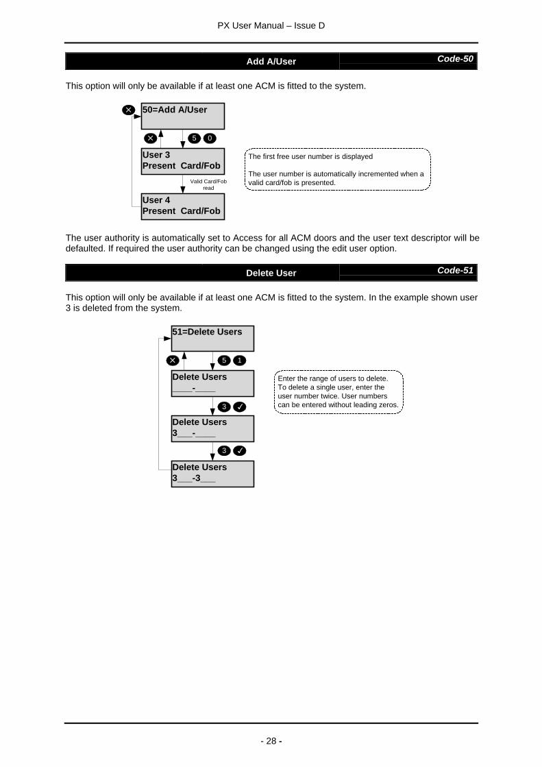
Delete User Code-51
This option will only be available if at least one ACM is fitted to the system. In the example shown user3 is deleted from the system.
51=Delete Users
Delete Users____-____
5 1
Enter the range of users to delete.To delete a single user, enter theuser number twice. User numberscan be entered without leading zeros.
Delete Users3___-____
3
Delete Users3___-3___
3
PX User Manual – Issue D
- 29 -
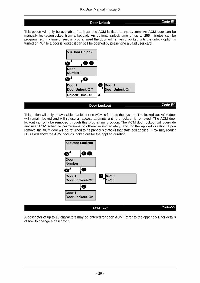
Door Unlock Code-53
This option will only be available if at least one ACM is fitted to the system. An ACM door can bemanually locked/unlocked from a keypad. An optional unlock time of up to 255 minutes can beprogrammed. If a time of zero is programmed the door will remain unlocked until the unlock option isturned off. While a door is locked it can still be opened by presenting a valid user card.
53=Door Unlock
DoorNumber _
5 3
1
Unlock Time-000
Door 1Door Unlock-On
1Door 1Door Unlock-Off
Door Lockout Code-54
This option will only be available if at least one ACM is fitted to the system. The locked out ACM doorwill remain locked and will refuse all access attempts until the lockout is removed. The ACM doorlockout can only be removed through this programming option. The ACM door lockout will over-rideany user/ACM schedule permissions or otherwise immediately, and for the applied duration. Uponremoval the ACM door will be returned to its previous state (if that state still applies). Proximity readerLED’s will show the ACM door as locked out for the applied duration.
54=Door Lockout
DoorNumber _
Door 1Door Lockout-Off
Door 1Door Lockout-On
1
0=Off1=On
?
1
45
ACM Text Code-55
A descriptor of up to 10 characters may be entered for each ACM. Refer to the appendix B for detailsof how to change a descriptor.
PX User Manual – Issue D
- 30 -
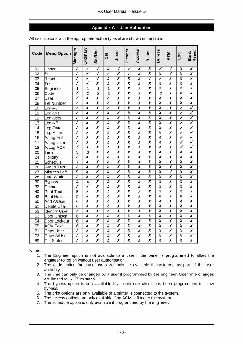
Appendix A – User Authorities
All user options with the appropriate authority level are shown in the table.
Code Menu Option
Man
ager
Ord
inar
y
Set/U
ns
Set
Uns
et
Cle
aner
Acc
ess
Res
et
Dur
ess
ATM Lo
g
Ban
kR
eset
01 Unset02 Set03 Reset04 Test05 Engineer 1 1 1 106 Code 2 2 2 207 User08 Tel Number10 Log-Full11 Log-Cct12 Log-User13 Log-KP14 Log-Date15 Log-Alarm16 A/Log-Full17 A/Log-User18 A/Log-ACM20 Time 3 324 Holiday25 Schedule 726 Group Text27 Minutes Left28 Late Work30 Bypass 4 432 Chime40 Print Text 542 Print Hols. 550 Add A/User 651 Delete User 652 Identify User53 Door Unlock 654 Door Lockout 655 ACM Text 671 Copy User73 Copy A/User89 Cct Status
Notes:1. The Engineer option is not available to a user if the panel is programmed to allow the
engineer to log on without user authorisation.2. The code option for some users will only be available if configured as part of the user
authority.3. The time can only be changed by a user if programmed by the engineer. User time changes
are limited to +/- 75 minutes.4. The bypass option is only available if at least one circuit has been programmed to allow
bypass.5. The print options are only available of a printer is connected to the system.6. The access options are only available if an ACM is fitted to the system7. The schedule option is only available if programmed by the engineer.
PX User Manual – Issue D
- 31 -
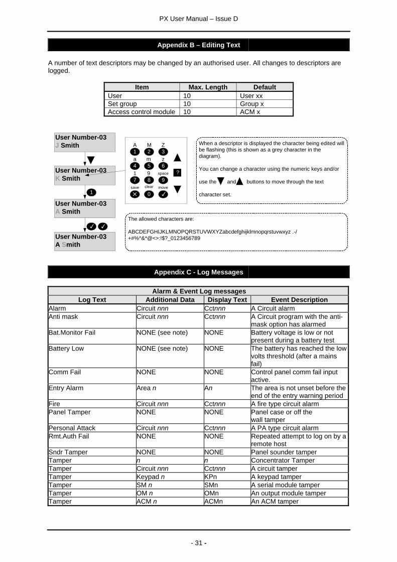
Appendix B – Editing Text
A number of text descriptors may be changed by an authorised user. All changes to descriptors arelogged.
Item Max. Length DefaultUser 10 User xxSet group 10 Group xAccess control module 10 ACM x
User Number-03J Smith
User Number-03K Smith
User Number-03A Smith
1
4 5 6
7 8 9
1A
2 3M Z
a m z
1 9
0
?
clear
space
save move
User Number-03A Smith
The allowed characters are:
ABCDEFGHIJKLMNOPQRSTUVWXYZabcdefghijklmnopqrstuvwxyz .-/+#%^&*@<>:!$?_0123456789
When a descriptor is displayed the character being edited willbe flashing (this is shown as a grey character in thediagram).
You can change a character using the numeric keys and/or
use the and buttons to move through the text
character set.
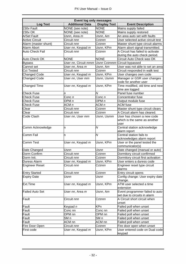
Appendix C - Log Messages
Alarm & Event Log messagesLog Text Additional Data Display Text Event Description
Alarm Circuit nnn Cctnnn A Circuit alarmAnti mask Circuit nnn Cctnnn A Circuit program with the anti-
mask option has alarmedBat.Monitor Fail NONE (see note) NONE Battery voltage is low or not
present during a battery testBattery Low NONE (see note) NONE The battery has reached the low
volts threshold (after a mainsfail)
Comm Fail NONE NONE Control panel comm fail inputactive.
Entry Alarm Area n An The area is not unset before theend of the entry warning period
Fire Circuit nnn Cctnnn A fire type circuit alarmPanel Tamper NONE NONE Panel case or off the
wall tamperPersonal Attack Circuit nnn Cctnnn A PA type circuit alarmRmt.Auth Fail NONE NONE Repeated attempt to log on by a
remote hostSndr Tamper NONE NONE Panel sounder tamperTamper n n Concentrator TamperTamper Circuit nnn Cctnnn A circuit tamperTamper Keypad n KPn A keypad tamperTamper SM n SMn A serial module tamperTamper OM n OMn An output module tamperTamper ACM n ACMn An ACM tamper
PX User Manual – Issue D
- 32 -
Event log only messagesLog Text Additional Data Display Text Event Description
230v Fault NONE (see note) NONE Mains supply failed230v OK NONE (see note) NONE Mains supply restoredA/Set Fault Usnn, Area m Usnn, Am An area auto set with faultsActive Circuit Circuit nnn Cctnnn User selected active circuit testAlarm (master shunt) Circuit nnn Cctnnn Master shunt type circuit alarmsAlarm Abort User nn, Keypad m Usnn, KPm Alarm abort signal transmitted.Auto Check Fail Circuit nnn Cctnnn A Circuit has failed to activate
during the auto check period.Auto Check OK NONE NONE Circuit Auto Check was OKBypass User nn, Circuit mmm Usnn Cctmmm Circuit bypassedCannot set User nn, Area m Usnn, Am User was not able to set an areaCct Tested Circuit nnn Cctnnn Circuit responded in walk testChanged Code User nn, Keypad m Usnn, KPm User changes own codeChanged Code User nn, User mm Usnn, Usmm Manager or GSR user changes
code for another userChanged Time User nn, Keypad m Usnn, KPm Time modified, old time and new
time are loggedCheck Fuse n N Panel fuse numberCheck Fuse Conc n Conc n Concentrator fuseCheck Fuse OPM n OPM n Output module fuseCheck Fuse ACM n ACM n ACM fuseClear Circuit nnn Cctnnn Master shunt type circuit clearsClear Circuit nnn Cctnnn A Circuit alarm has cleared.Code Clash User nn, User mm Usnn, Usmm User has chosen a new code
which is the same as anotheruser
Comm Acknowledge n N Central station acknowledgealarm report
Comm Fail n N Central station fails toacknowledges alarm report
Comm Test User nn, Keypad m Usnn, KPm User or the panel tested thecommunicator(s)
Date Changed Usnn Usnn Date changed (manual or auto)Dorm Confirm Circuit nnn Cctnnn Dormitory circuit confirmedDorm Init. Circuit nnn Cctnnn Dormitory circuit first activationDuress Alarm User nn, Keypad m Usnn, KPm User enters a duress codeEngineer Reset Circuit nnn Cctnnn Engineer reset type circuit
alarmsEntry Started Circuit nnn Cctnnn Entry circuit opensExpiry Date Usnn Usnn Config change: User expiry date
change.Ext.Time User nn, Keypad m Usnn, KPm ATM user selected a time
extensionFailed Auto Set User nn, Area m Usnn, Am Event programmer failed to auto
set due to circuits in alarmFault Circuit nnn Cctnnn A Circuit short circuit when
unsetFault Keypad n KPn Failed poll when unsetFault Conc nn Conc nn Failed poll when unsetFault OPM nn OPM nn Failed poll when unsetFault SM n SM n Failed poll when unsetFault ACM nn ACM nn Failed poll when unsetFire Door Open Circuit nnn Cctnnn Fire door open when unsetFirst code User nn, Keypad m Usnn, KPm User entered code on Dual code
keypad
PX User Manual – Issue D
- 33 -
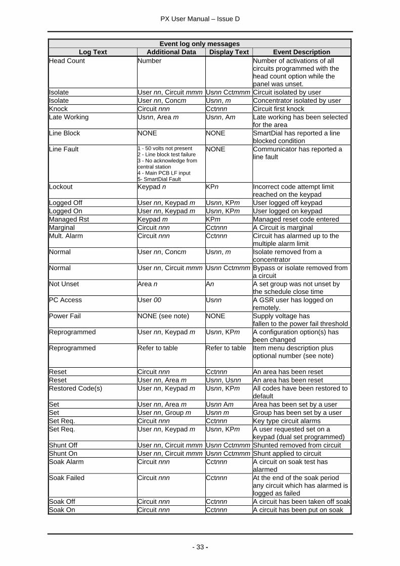
Event log only messagesLog Text Additional Data Display Text Event Description
Head Count Number Number of activations of allcircuits programmed with thehead count option while thepanel was unset.
Isolate User nn, Circuit mmm Usnn Cctmmm Circuit isolated by userIsolate User nn, Concm Usnn, m Concentrator isolated by userKnock Circuit nnn Cctnnn Circuit first knockLate Working Usnn, Area m Usnn, Am Late working has been selected
for the areaLine Block NONE NONE SmartDial has reported a line
blocked conditionLine Fault 1 - 50 volts not present
2 - Line block test failure3 - No acknowledge fromcentral station4 - Main PCB LF input5- SmartDial Fault
NONE Communicator has reported aline fault
Lockout Keypad n KPn Incorrect code attempt limitreached on the keypad
Logged Off User nn, Keypad m Usnn, KPm User logged off keypadLogged On User nn, Keypad m Usnn, KPm User logged on keypadManaged Rst Keypad m KPm Managed reset code enteredMarginal Circuit nnn Cctnnn A Circuit is marginalMult. Alarm Circuit nnn Cctnnn Circuit has alarmed up to the
multiple alarm limitNormal User nn, Concm Usnn, m Isolate removed from a
concentratorNormal User nn, Circuit mmm Usnn Cctmmm Bypass or isolate removed from
a circuitNot Unset Area n An A set group was not unset by
the schedule close timePC Access User 00 Usnn A GSR user has logged on
remotely.Power Fail NONE (see note) NONE Supply voltage has
fallen to the power fail thresholdReprogrammed User nn, Keypad m Usnn, KPm A configuration option(s) has
been changedReprogrammed Refer to table Refer to table Item menu description plus
optional number (see note)
Reset Circuit nnn Cctnnn An area has been resetReset User nn, Area m Usnn, Usnn An area has been resetRestored Code(s) User nn, Keypad m Usnn, KPm All codes have been restored to
defaultSet User nn, Area m Usnn Am Area has been set by a userSet User nn, Group m Usnn m Group has been set by a userSet Req. Circuit nnn Cctnnn Key type circuit alarmsSet Req. User nn, Keypad m Usnn, KPm A user requested set on a
keypad (dual set programmed)Shunt Off User nn, Circuit mmm Usnn Cctmmm Shunted removed from circuitShunt On User nn, Circuit mmm Usnn Cctmmm Shunt applied to circuitSoak Alarm Circuit nnn Cctnnn A circuit on soak test has
alarmedSoak Failed Circuit nnn Cctnnn At the end of the soak period
any circuit which has alarmed islogged as failed
Soak Off Circuit nnn Cctnnn A circuit has been taken off soakSoak On Circuit nnn Cctnnn A circuit has been put on soak
PX User Manual – Issue D
- 34 -
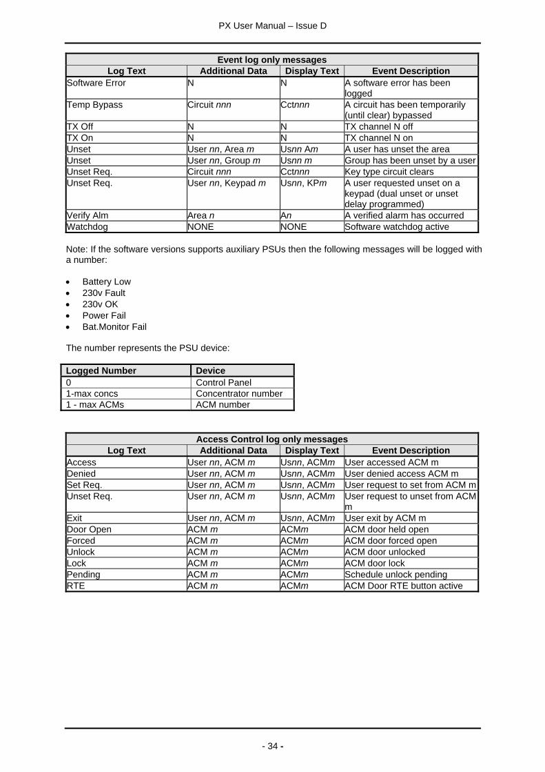
Event log only messagesLog Text Additional Data Display Text Event Description
Software Error N N A software error has beenlogged
Temp Bypass Circuit nnn Cctnnn A circuit has been temporarily(until clear) bypassed
TX Off N N TX channel N offTX On N N TX channel N onUnset User nn, Area m Usnn Am A user has unset the areaUnset User nn, Group m Usnn m Group has been unset by a userUnset Req. Circuit nnn Cctnnn Key type circuit clearsUnset Req. User nn, Keypad m Usnn, KPm A user requested unset on a
keypad (dual unset or unsetdelay programmed)
Verify Alm Area n An A verified alarm has occurredWatchdog NONE NONE Software watchdog active
Note: If the software versions supports auxiliary PSUs then the following messages will be logged witha number:
• Battery Low• 230v Fault• 230v OK• Power Fail• Bat.Monitor Fail
The number represents the PSU device:
Logged Number Device0 Control Panel1-max concs Concentrator number1 - max ACMs ACM number
Access Control log only messagesLog Text Additional Data Display Text Event Description
Access User nn, ACM m Usnn, ACMm User accessed ACM mDenied User nn, ACM m Usnn, ACMm User denied access ACM mSet Req. User nn, ACM m Usnn, ACMm User request to set from ACM mUnset Req. User nn, ACM m Usnn, ACMm User request to unset from ACM
mExit User nn, ACM m Usnn, ACMm User exit by ACM mDoor Open ACM m ACMm ACM door held openForced ACM m ACMm ACM door forced openUnlock ACM m ACMm ACM door unlockedLock ACM m ACMm ACM door lockPending ACM m ACMm Schedule unlock pendingRTE ACM m ACMm ACM Door RTE button active
PX User Manual – Issue D
- 35 -
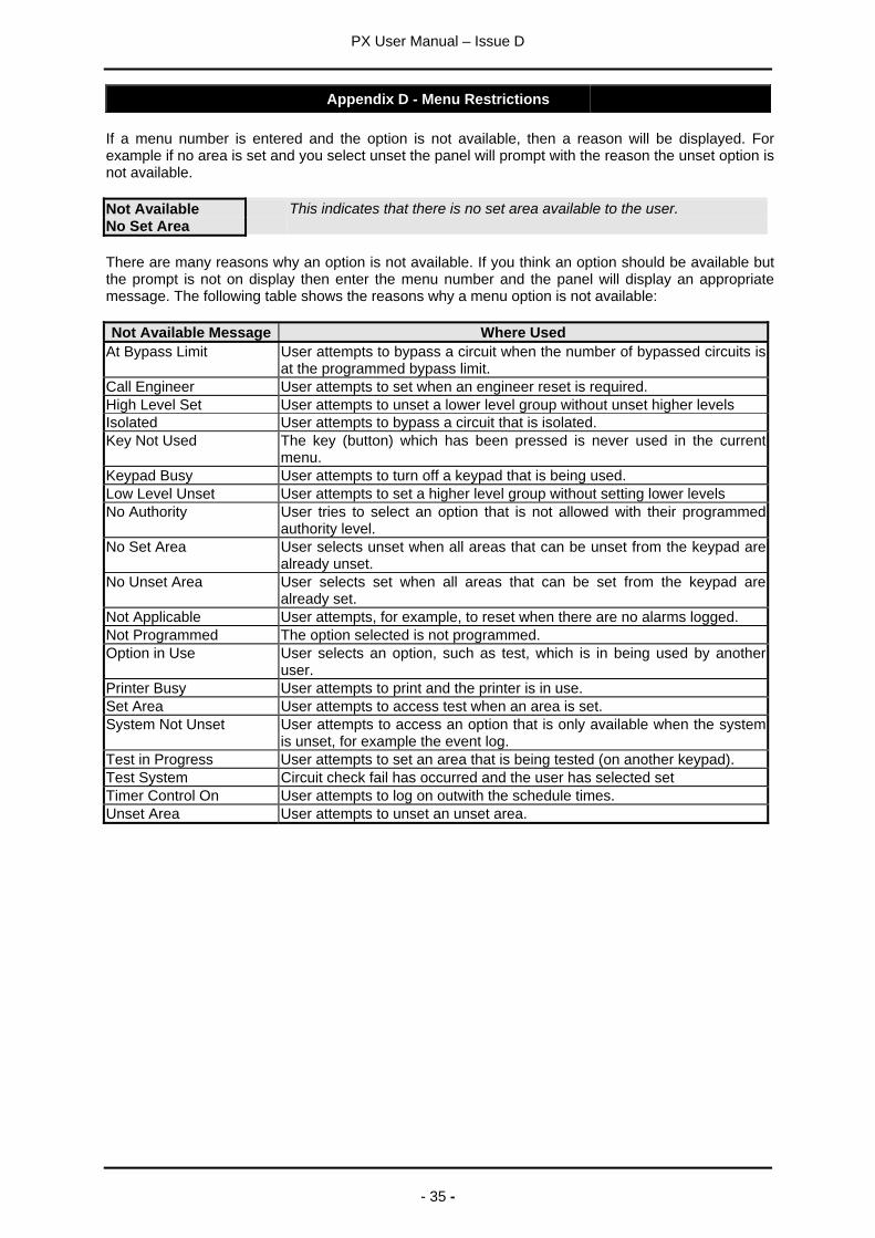
Appendix D - Menu Restrictions
If a menu number is entered and the option is not available, then a reason will be displayed. Forexample if no area is set and you select unset the panel will prompt with the reason the unset option isnot available.
Not AvailableNo Set Area
This indicates that there is no set area available to the user.
There are many reasons why an option is not available. If you think an option should be available butthe prompt is not on display then enter the menu number and the panel will display an appropriatemessage. The following table shows the reasons why a menu option is not available:
Not Available Message Where UsedAt Bypass Limit User attempts to bypass a circuit when the number of bypassed circuits is
at the programmed bypass limit.Call Engineer User attempts to set when an engineer reset is required.High Level Set User attempts to unset a lower level group without unset higher levelsIsolated User attempts to bypass a circuit that is isolated.Key Not Used The key (button) which has been pressed is never used in the current
menu.Keypad Busy User attempts to turn off a keypad that is being used.Low Level Unset User attempts to set a higher level group without setting lower levelsNo Authority User tries to select an option that is not allowed with their programmed
authority level.No Set Area User selects unset when all areas that can be unset from the keypad are
already unset.No Unset Area User selects set when all areas that can be set from the keypad are
already set.Not Applicable User attempts, for example, to reset when there are no alarms logged.Not Programmed The option selected is not programmed.Option in Use User selects an option, such as test, which is in being used by another
user.Printer Busy User attempts to print and the printer is in use.Set Area User attempts to access test when an area is set.System Not Unset User attempts to access an option that is only available when the system
is unset, for example the event log.Test in Progress User attempts to set an area that is being tested (on another keypad).Test System Circuit check fail has occurred and the user has selected setTimer Control On User attempts to log on outwith the schedule times.Unset Area User attempts to unset an unset area.

PX User Manual – Issue D
- 36 -
Appendix E - Log On Messages
When a user logs on, the system may display a special message(s) before the normal menu isdisplayed. The special messages are shown in the table.
Message ReasonAlarm Abort User logs on within the alarm abort period (programmable option)Call Engineer You should call the installation company. The details will then be displayed.Cannot Set The system cannot set, the reason(s) will then be displayed.Code Known Another user has chosen your code. You will then be given the option of
immediately changing your code. This message will always be displayed onlog on until the code is changed.
Group Unset A group(s) is set and is programmed to automatically unset when a user logson.
Mult.Alarm A circuit(s) has alarmed the maximum number of times allowed(programmable). The circuit details will then be displayed.
Reset OK A managed reset code has been acceptedSetting Stopped User logs on during the setting exit periodSoak Cct Fails Circuits which have been put on special test by the installation engineer have
alarmed.Unset Alarm An unset alarm has occurred, the details will then be displayed.
PX User Manual – Issue D
- 37 -
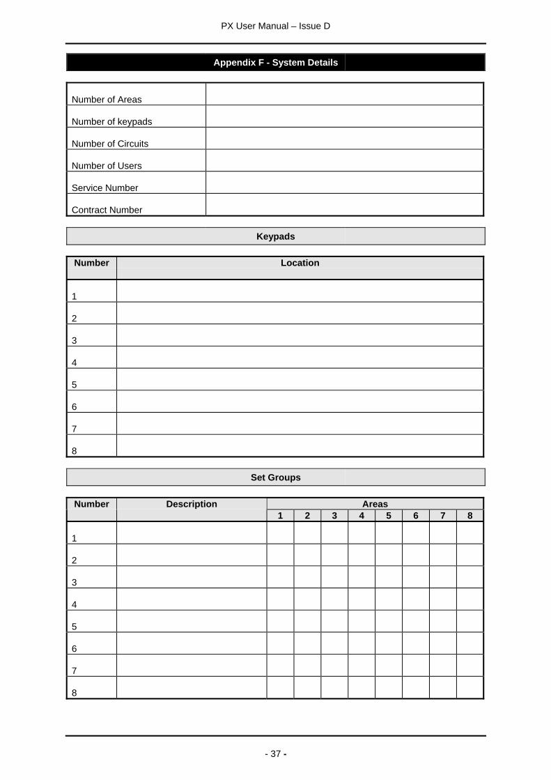
Appendix F - System Details
Number of Areas
Number of keypads
Number of Circuits
Number of Users
Service Number
Contract Number
Keypads
Number Location
1
2
3
4
5
6
7
8
Set Groups
AreasNumber Description1 2 3 4 5 6 7 8
1
2
3
4
5
6
7
8
PX User Manual – Issue D
- 38 -
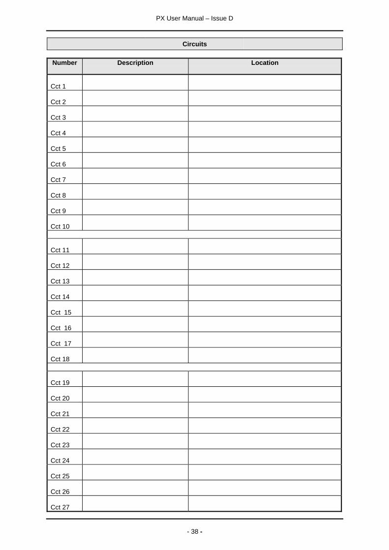
Circuits
Number Description Location
Cct 1
Cct 2
Cct 3
Cct 4
Cct 5
Cct 6
Cct 7
Cct 8
Cct 9
Cct 10
Cct 11
Cct 12
Cct 13
Cct 14
Cct 15
Cct 16
Cct 17
Cct 18
Cct 19
Cct 20
Cct 21
Cct 22
Cct 23
Cct 24
Cct 25
Cct 26
Cct 27
PX User Manual – Issue D
- 39 -
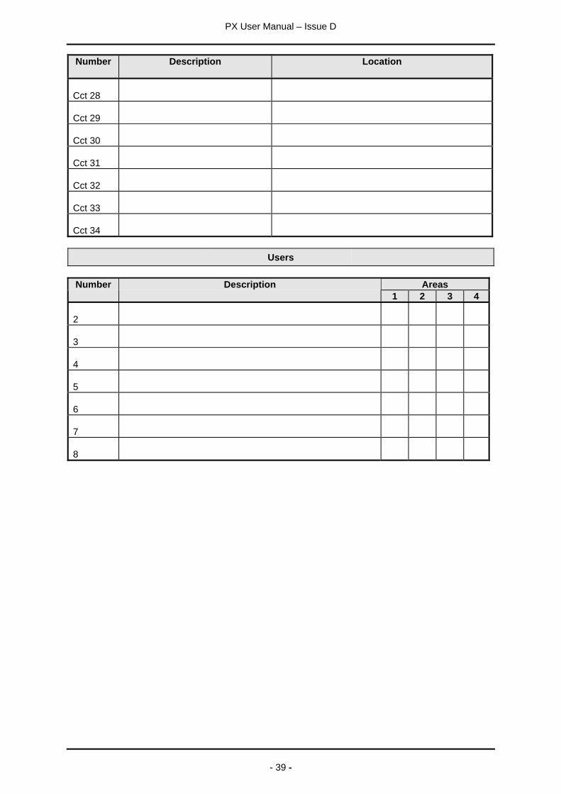
Number Description Location
Cct 28
Cct 29
Cct 30
Cct 31
Cct 32
Cct 33
Cct 34
Users
AreasNumber Description1 2 3 4
2
3
4
5
6
7
8

Guardall LimitedLochend Industrial Estate
NewbridgeEdinburgh EH28 8PL
Tel: 0131-333-2900FAX: 0131-333-4919
Technical Hotline: 0131-333-3802
Part Number: 320680-0D