Embed Size (px)
Citation preview
新一代顯示介面之驗證與測試新一代顯示介面之驗證與測試新一代顯示介面之驗證與測試新一代顯示介面之驗證與測試
Brian Chen 太克科技 應用工程師

Agenda
�HDMI Overview and updates
�MHL Overview and updates
�DP overview and updates
�Tektronix Solution overview
�Additional resources
TIF - Validating Next Generation Display Interfaces
HDMI –High Definition Multimedia Interface
TIF - Validating Next Generation Display Interfaces
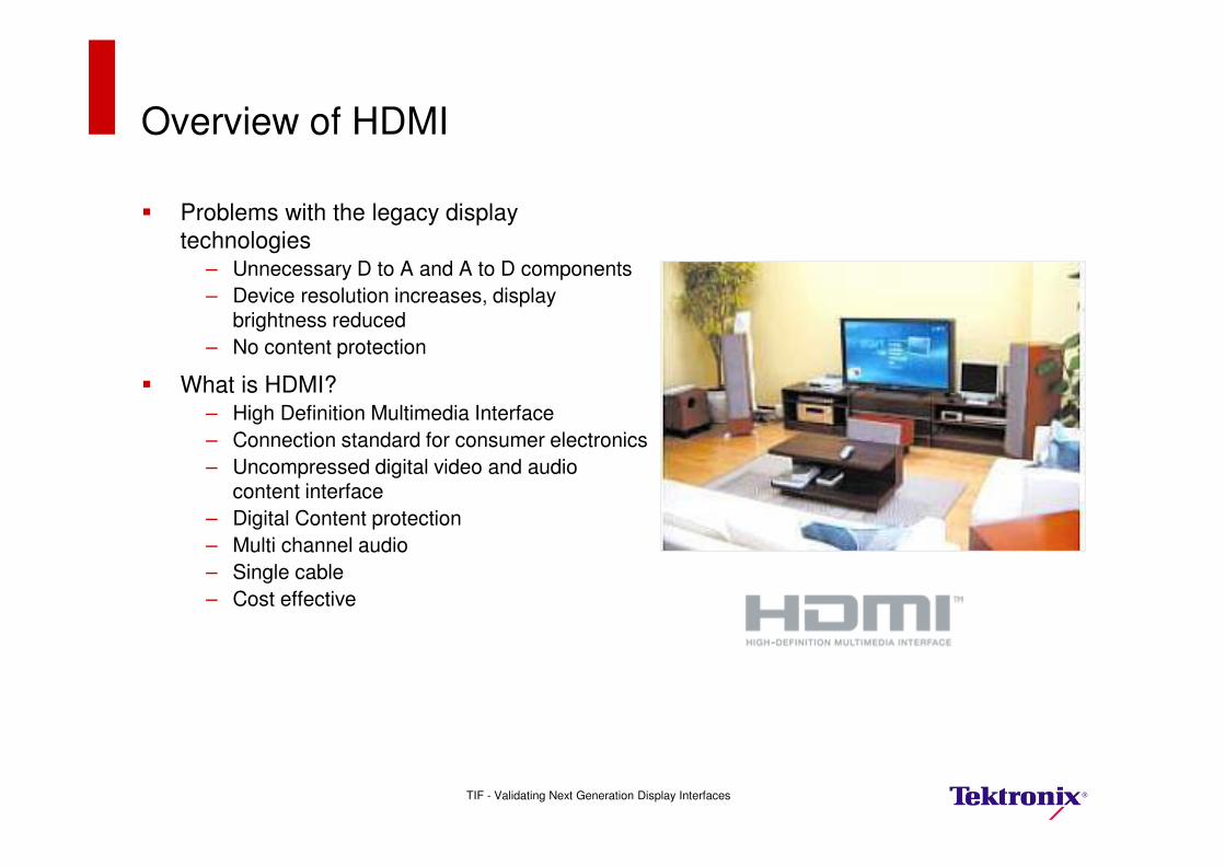
Overview of HDMI
� Problems with the legacy display
technologies– Unnecessary D to A and A to D components
– Device resolution increases, display brightness reduced
– No content protection
� What is HDMI? – High Definition Multimedia Interface
– Connection standard for consumer electronics
– Uncompressed digital video and audio content interface
– Digital Content protection
– Multi channel audio
– Single cable
– Cost effective
TIF - Validating Next Generation Display Interfaces

HDMI Basics
TIF - Validating Next Generation Display Interfaces

HDMI Technology and solution status
� Over 1000+ adopters till date
� HDMI Expands Footprint
– HDMI has made inroads into PC industry– New computer platforms have HDMI interfaces
– Hand held devices with miniature HDMI devices– New connectors Type C and Type D introduced
– HDMI Forays into Automotive – Type E
– Year 2011 – 3D Year
– Still camera
– Advertising billboards
� HDMI NOW Truly Single Digital Interconnect for uncompressed Audio/Video
– HEAC ( A R C)
Source: HDMI LLC
TIF - Validating Next Generation Display Interfaces
Ethernet up-linkAudio up-link
HEAC
Source
HEAC Cable
Ethernet down-link
HEAC Sink
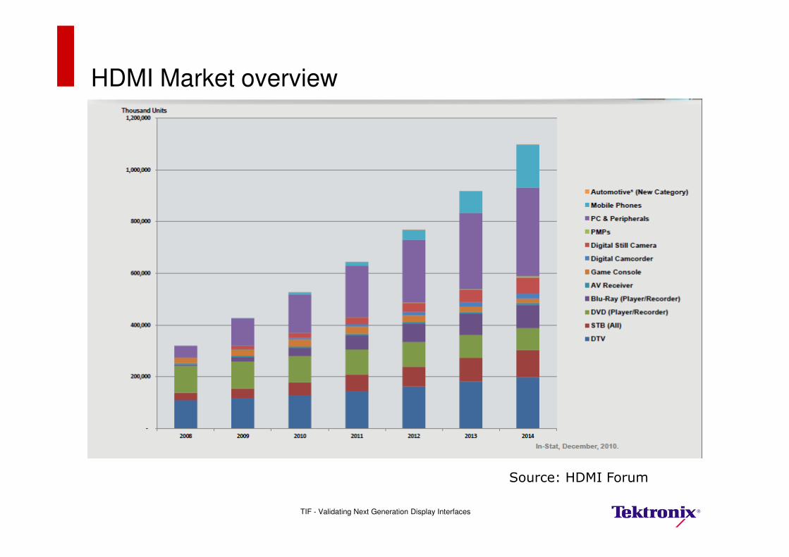
HDMI Market overview
TIF - Validating Next Generation Display Interfaces
Source: HDMI Forum
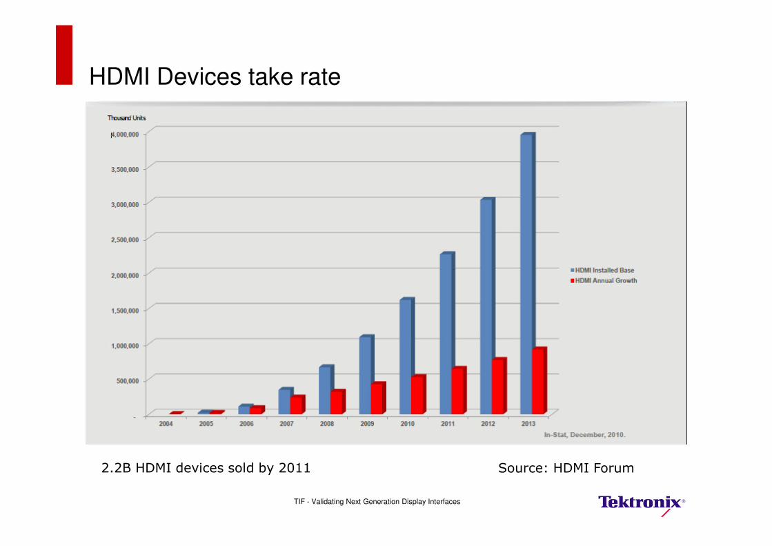
HDMI Devices take rate
TIF - Validating Next Generation Display Interfaces
Source: HDMI Forum2.2B HDMI devices sold by 2011
HDMI Status
� Complementing/Competing
– MHL ( Mobile High Definition Link)
� Competing Technologies
– Wireless HDMI ( Wimedia, Wireless USB etc)
– WiHD ( 60GHz LOS)!!!
– WHDI (5GHz)
– DP
TIF - Validating Next Generation Display Interfaces
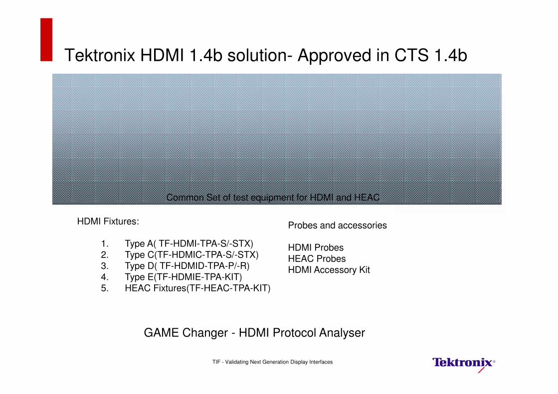
Tektronix HDMI 1.4b solution- Approved in CTS 1.4b
DPO/DSA/MSO Real Time Oscilloscopes
AWG5K/B or AWG7K/B Arbitrary Waveform Generators
DSA8200 Sampling Scope with i-connect software
Common Set of test equipment for HDMI and HEAC
HDMI Fixtures:
1. Type A( TF-HDMI-TPA-S/-STX)2. Type C(TF-HDMIC-TPA-S/-STX)3. Type D( TF-HDMID-TPA-P/-R)4. Type E(TF-HDMIE-TPA-KIT)5. HEAC Fixtures(TF-HEAC-TPA-KIT)
Probes and accessories
HDMI ProbesHEAC ProbesHDMI Accessory Kit
GAME Changer - HDMI Protocol Analyser
TIF - Validating Next Generation Display Interfaces

Changes in HDMI standards body
TIF - Validating Next Generation Display Interfaces
Source: HDMI Forum

What is HDMI Forum
TIF - Validating Next Generation Display Interfaces
Source: HDMI Forum
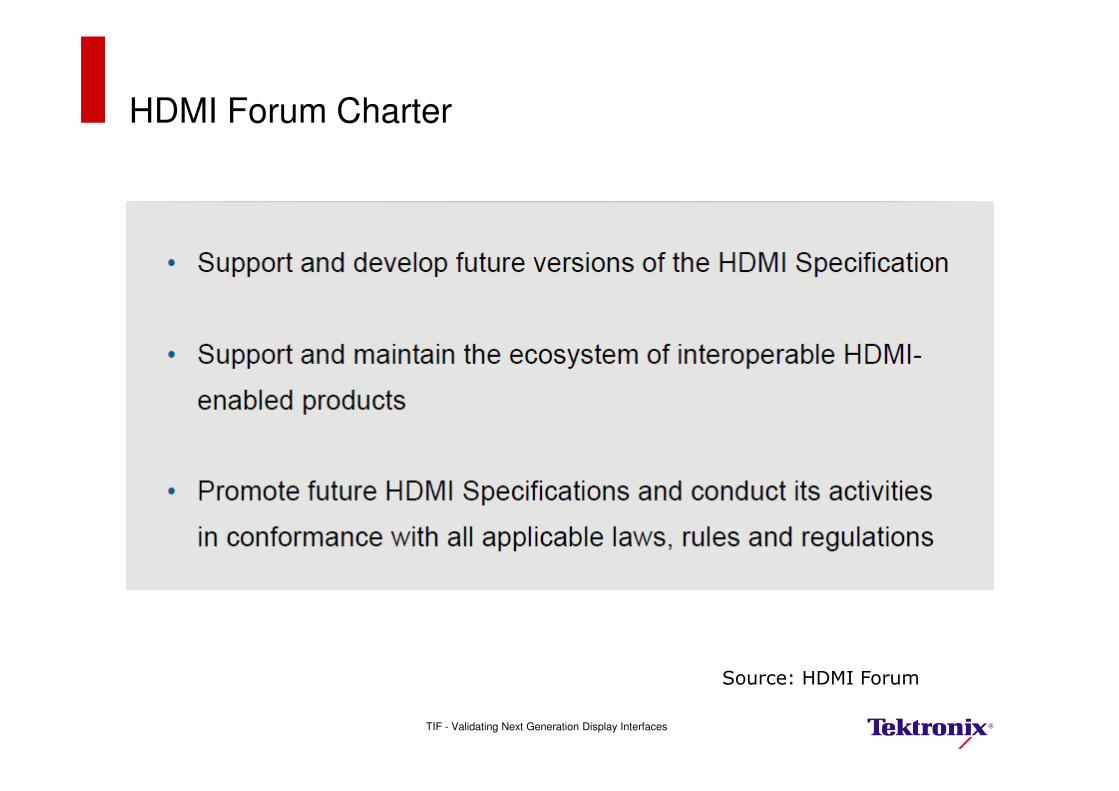
HDMI Forum Charter
TIF - Validating Next Generation Display Interfaces
Source: HDMI Forum
Tektronix and HDMI Forum
�80+ companies in the HDMI forum as of date. source HDMI Forum
�Tektronix is member of this HDMI Forum. Actively participating in weekly/monthly calls and face-face meetings
�Tektronix’s U.N.Vasudev is co-chair for HDMI forum test sub-group
�HDMI Forum working on next version of HDMI specifications.
– Target – 2013 Q3 Specification
– CTS 2013 Q4
TIF - Validating Next Generation Display Interfaces
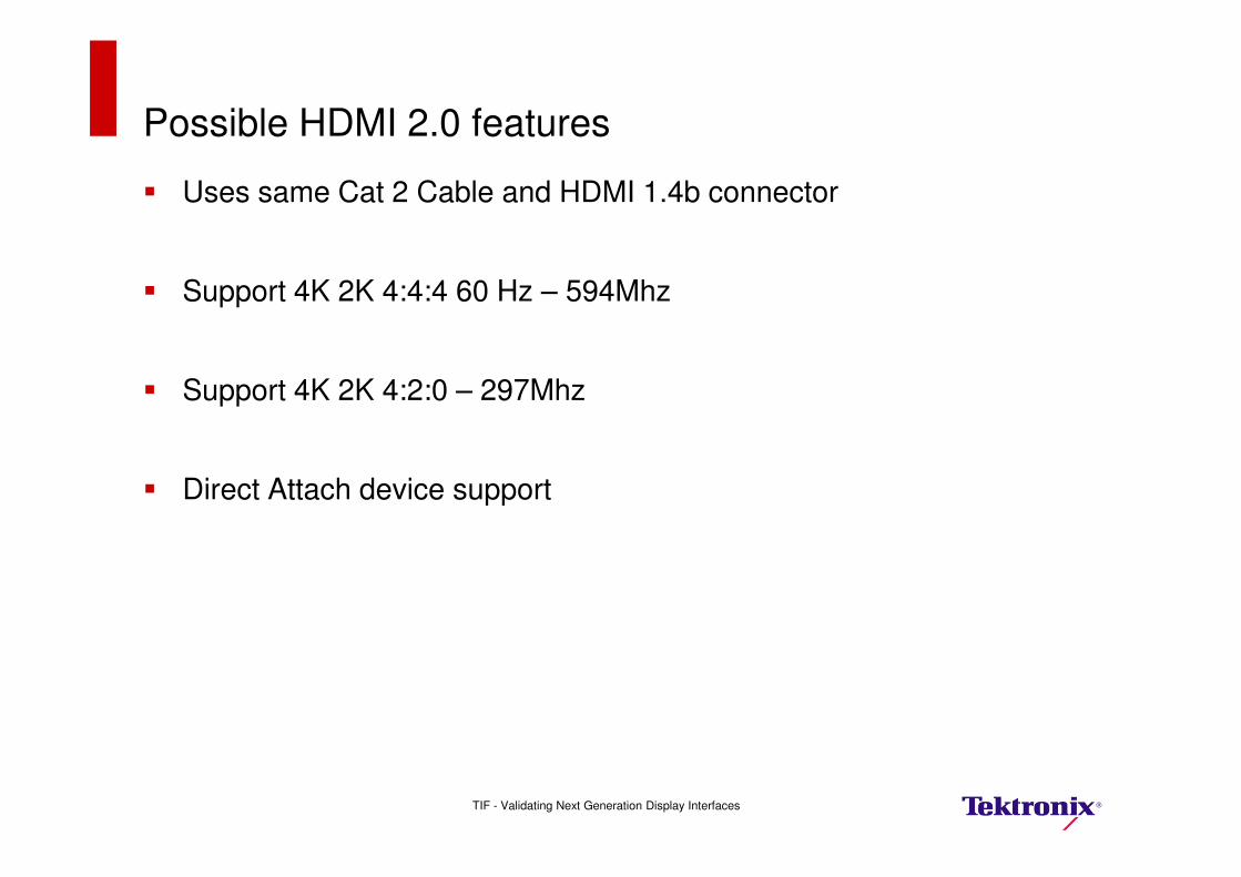
Possible HDMI 2.0 features
� Uses same Cat 2 Cable and HDMI 1.4b connector
� Support 4K 2K 4:4:4 60 Hz – 594Mhz
� Support 4K 2K 4:2:0 – 297Mhz
� Direct Attach device support
TIF - Validating Next Generation Display Interfaces
HDMI 2.0 Source Testing-Advanced information
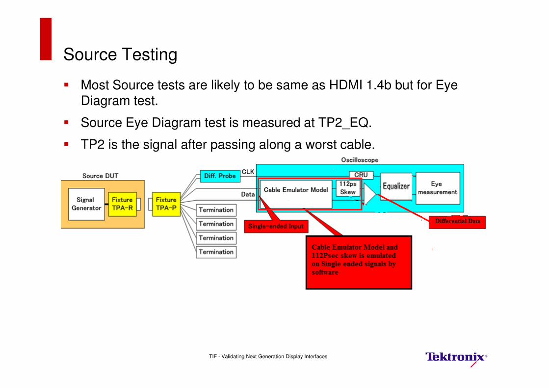
Source Testing
� Most Source tests are likely to be same as HDMI 1.4b but for Eye Diagram test.
� Source Eye Diagram test is measured at TP2_EQ.
� TP2 is the signal after passing along a worst cable.
– Worst cable has worst attenuation and skew of 112ps.
TIF - Validating Next Generation Display Interfaces
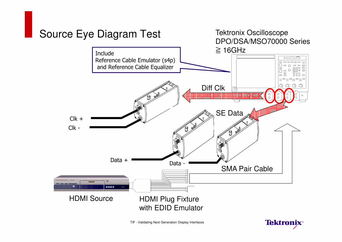
Source Eye Diagram Test
SMA Pair Cable
HDMI Source
Clk +
Clk -
Tektronix Oscilloscope
DPO/DSA/MSO70000 Series≧ 16GHzInclude
Reference Cable Emulator (s4p)and Reference Cable Equalizer
HDMI Plug Fixturewith EDID Emulator
Data +Data -
Diff Clk
SE Data
TIF - Validating Next Generation Display Interfaces
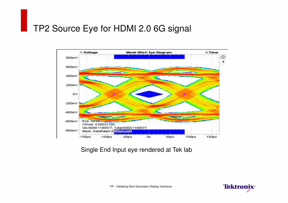
TP2 Source Eye for HDMI 2.0 6G signal
Single End Input eye rendered at Tek lab
TIF - Validating Next Generation Display Interfaces
HDMI 2.0 Sink Testing- Advanced Information
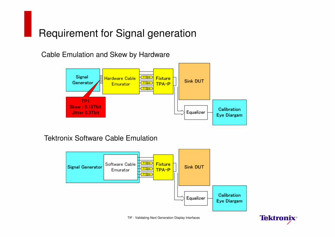
Requirement for Signal generation
Tektronix Software Cable Emulation
Cable Emulation and Skew by Hardware
TIF - Validating Next Generation Display Interfaces

Sink Test
HDMI Sink
HDMI Plug Fixture
Tektronix AFG3000
(Synchronize two AWGs)
Tektronix AWG7002A x 2
Tektronix Oscilloscope
DPO/DSA/MSO70000 Series(Synchronize two AWGs
and Automation Test)
SMA Pair Cable112ps Delay Line(Emulate Cable Skew)
IncludeReference Cable Emulator (s2p)
TIF - Validating Next Generation Display Interfaces

TP2 Signal with New AWG70002A
Direct Synthesis capability to add impairments in Software
Skew effectCable emulator effect
Delay effect
TP2 Eye after applying Cable Equalizer
TIF - Validating Next Generation Display Interfaces
Tektronix HDMI 2.0 Solution
� Tektronix HDMI 2.0 Solution will be available aligned to the CTS announcement from the new HDMI Forum.
� Full Source, Sink, Cable and Protocol Solution including probes, Fixtures.
� Support for HDMI 1.4b CTS which is likely to be a pre-requiste for HDMI 2.0 testing.
� Contact local Tektronix sales team for early interaction on our HDMI 2.0 solution.
TIF - Validating Next Generation Display Interfaces

MHL – Mobile High Definition Link
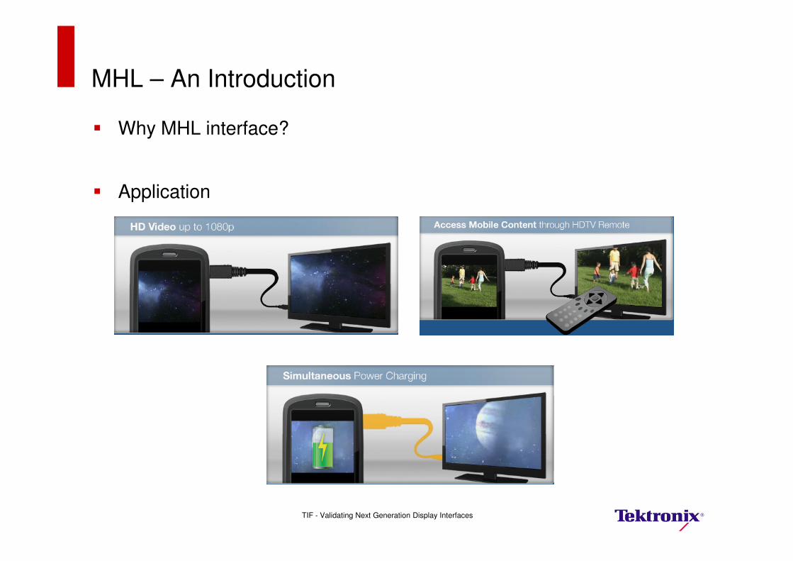
MHL – An Introduction
� Why MHL interface?
� Application
TIF - Validating Next Generation Display Interfaces
MHL Introduction
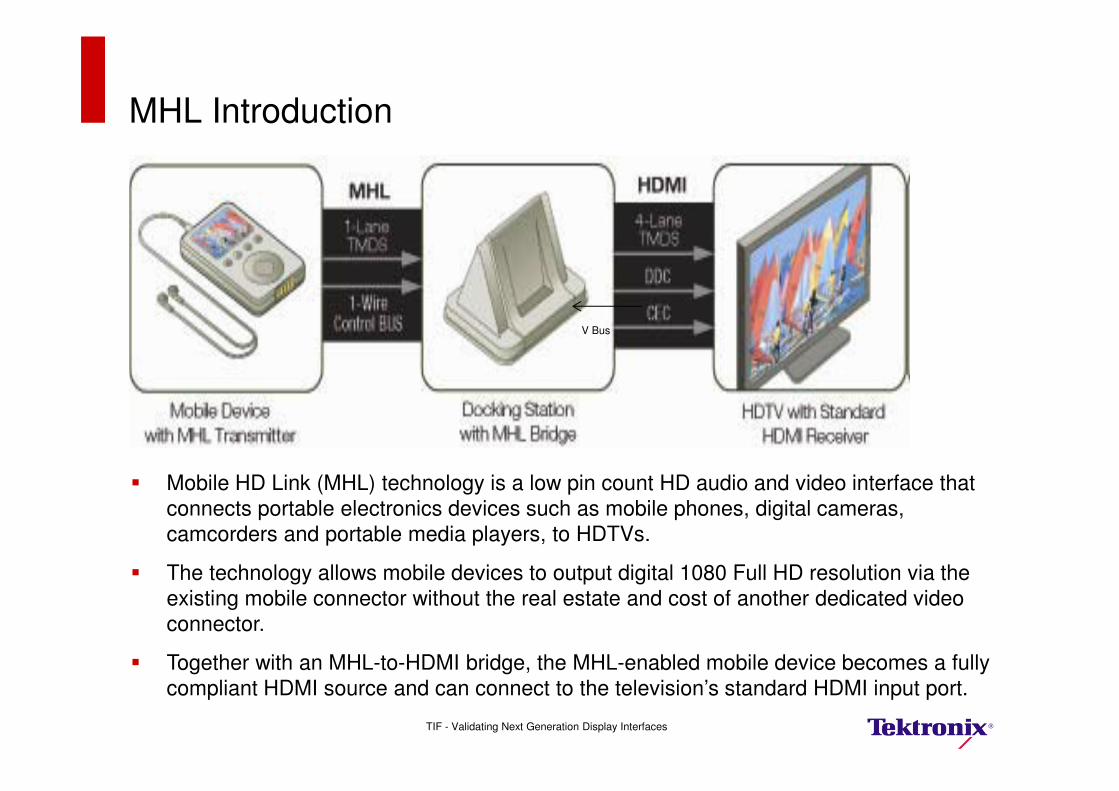
� Mobile HD Link (MHL) technology is a low pin count HD audio and video interface that
connects portable electronics devices such as mobile phones, digital cameras,
camcorders and portable media players, to HDTVs.
� The technology allows mobile devices to output digital 1080 Full HD resolution via the
existing mobile connector without the real estate and cost of another dedicated video
connector.
� Together with an MHL-to-HDMI bridge, the MHL-enabled mobile device becomes a fully
compliant HDMI source and can connect to the television’s standard HDMI input port.
V Bus
TIF - Validating Next Generation Display Interfaces
MHL Introduction
TIF - Validating Next Generation Display Interfaces
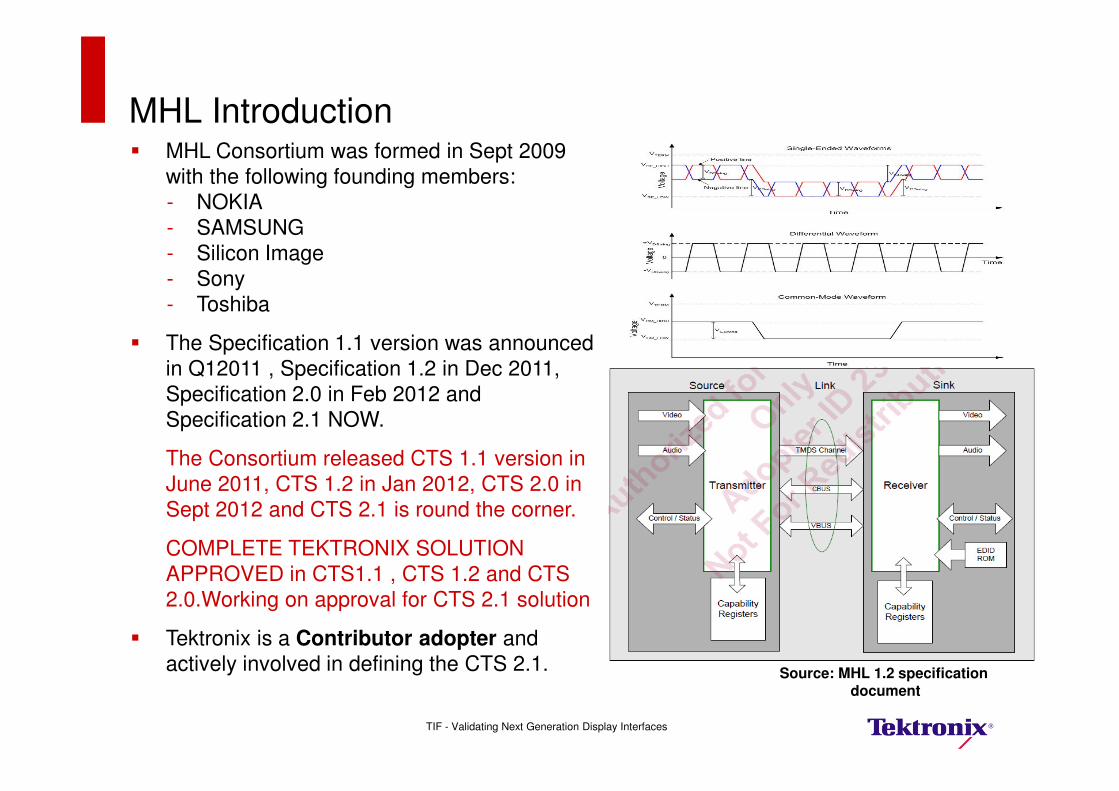
Source: MHL 1.2 specification document
� MHL Consortium was formed in Sept 2009
with the following founding members:
- NOKIA
- SAMSUNG
- Silicon Image
- Sony
- Toshiba
� The Specification 1.1 version was announced
in Q12011 , Specification 1.2 in Dec 2011,
Specification 2.0 in Feb 2012 and
Specification 2.1 NOW.
The Consortium released CTS 1.1 version in
June 2011, CTS 1.2 in Jan 2012, CTS 2.0 in
Sept 2012 and CTS 2.1 is round the corner.
COMPLETE TEKTRONIX SOLUTION
APPROVED in CTS1.1 , CTS 1.2 and CTS
2.0.Working on approval for CTS 2.1 solution
� Tektronix is a Contributor adopter and
actively involved in defining the CTS 2.1.
MHL CTS 2.1 features and next steps
� New test method for Clk Jitter and Data Eye Diagram ( will be Single ended connection)
� Direct Attach devices support.
� New tests for Cable testing
– Cable Eye Diagram
– Minimum Voltage level
� Sink testing with and without Cable emulator effect
TIF - Validating Next Generation Display Interfaces
� NEXT Steps
– MHL Consortium working on next version MHL specifications.– Data rate ???
Tektronix MHL Solution: Complete Solution Aligned to CTS2.1 Announcement
� Tektronix MHL Physical Layer Tx test setups are easy to use and automated
- Simple test setups common for most tests
- Vterm provided by scope itself
- MHL Fixtures available from our Fixture partner Wilder Technologies
� Tektronix MHL Physical Layer Rx test setups are easy to use.
- TRUE MHL SIGNAL Generation as there is no need for external combiners/Filters
- No need for external ISI boards as we leverage our AWG direct Synthesis
Capability with common setups for Sink and Dongle testing
� Tektronix introduces an innovative combined solution for Physical Layer Testing and
Protocol Testing:
- Providing seamless link between PHY and Link layer testing
- An economical MHL test solution
o ONE BOX solution for PHY and Protocol testing
- Easy access to legacy P/A/V data format
� Tektronix also offers complete MHL solution with:
- DSA8200 or Equivalent Sampling scope with 80E03/04 and I-connect Software for
MHL Cable testing (performed manually using MOIs)
- Low Bandwidth Oscilloscopes
- Keithley Source Meter (Now part of Tektronix)
- Programmable Power Supply and
- Digital Millimeter
TIF - Validating Next Generation Display Interfaces
DisplayPort 1.2 and eDP Testing Update
DisplayPort 1.2 Spec Update Agenda
� DisplayPort 1.2 Overview
� DisplayPort Transmitter Testing– What’s New: T2, TP3, TP3EQ– Physical Layer Test Overview for DP1.2
– Manual measurements / DPOJET / SDLA– CTLE required in Rx
– DP-AUX: Control DUT parameters– Controls ALL TX. RX devices without vendor-specific control SW
� Test Automation:– Full Main Link testing with DP12 Automated tool set– DP 1.2 Tx:
– Including Single-Ended and Diff Measurements (Intra-Pair Skew, AC Common Mode)
– Using RF Switch Integration– Improved Debug Tools
� DisplayPort Sink/Receiver Testing– BSA125C configurations towards Rx testing
– Jitter Impairment profile and observation times
� eDP testing for eDP 1.4 specification
Reference: VESA® DisplayPort® PHY Compliance Test Specification Version 1.2
TIF - Validating Next Generation Display Interfaces
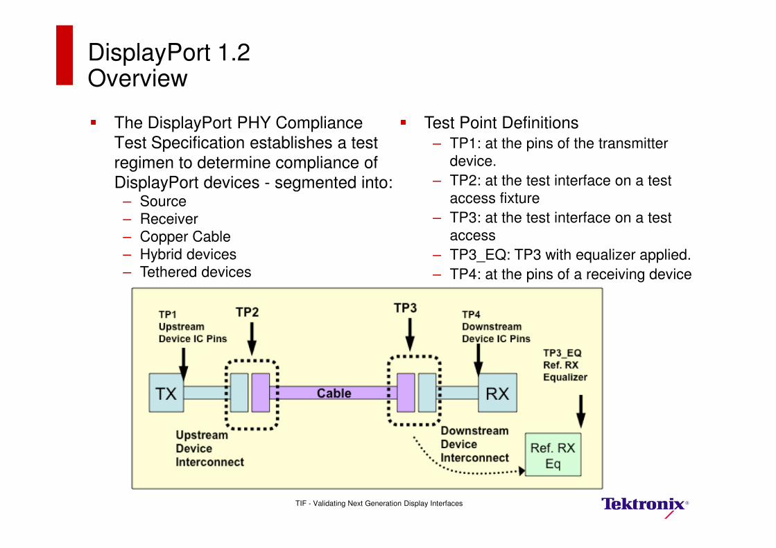
DisplayPort 1.2 Overview
� The DisplayPort PHY Compliance Test Specification establishes a test
regimen to determine compliance of
DisplayPort devices - segmented into: – Source
– Receiver
– Copper Cable
– Hybrid devices
– Tethered devices
� Test Point Definitions– TP1: at the pins of the transmitter
device.
– TP2: at the test interface on a test
access fixture
– TP3: at the test interface on a test
access
– TP3_EQ: TP3 with equalizer applied.
– TP4: at the pins of a receiving device
TIF - Validating Next Generation Display Interfaces
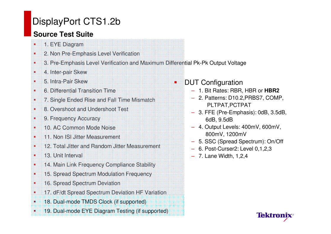
Source Test Suite
� 1. EYE Diagram
� 2. Non Pre-Emphasis Level Verification
� 3. Pre-Emphasis Level Verification and Maximum Differential Pk-Pk Output Voltage
� 4. Inter-pair Skew
� 5. Intra-Pair Skew
� 6. Differential Transition Time
� 7. Single Ended Rise and Fall Time Mismatch
� 8. Overshoot and Undershoot Test
� 9. Frequency Accuracy
� 10. AC Common Mode Noise
� 11. Non ISI Jitter Measurement
� 12. Total Jitter and Random Jitter Measurement
� 13. Unit Interval
� 14. Main Link Frequency Compliance Stability
� 15. Spread Spectrum Modulation Frequency
� 16. Spread Spectrum Deviation
� 17. dF/dt Spread Spectrum Deviation HF Variation
� 18. Dual-mode TMDS Clock (if supported)
� 19. Dual-mode EYE Diagram Testing (if supported)
DisplayPort CTS1.2b
� DUT Configuration– 1. Bit Rates: RBR, HBR or HBR2
– 2. Patterns: D10.2,PRBS7, COMP,
PLTPAT,PCTPAT
– 3. FFE (Pre-Emphasis): 0dB, 3.5dB,
6dB, 9.5dB
– 4. Output Levels: 400mV, 600mV,
800mV, 1200mV
– 5. SSC (Spread Spectrum): On/Off
– 6. Post-Curser2: Level 0,1,2,3
– 7. Lane Width, 1,2,4
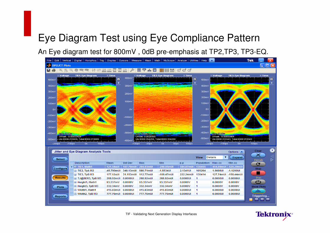
Eye Diagram Test using Eye Compliance Pattern
An Eye diagram test for 800mV , 0dB pre-emphasis at TP2,TP3, TP3-EQ.
TIF - Validating Next Generation Display Interfaces
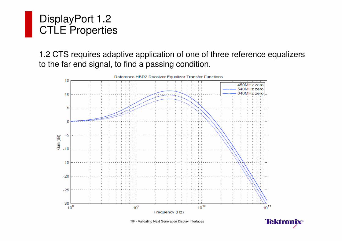
DisplayPort 1.2 CTLE Properties
1.2 CTS requires adaptive application of one of three reference equalizers to the far end signal, to find a passing condition.
TIF - Validating Next Generation Display Interfaces
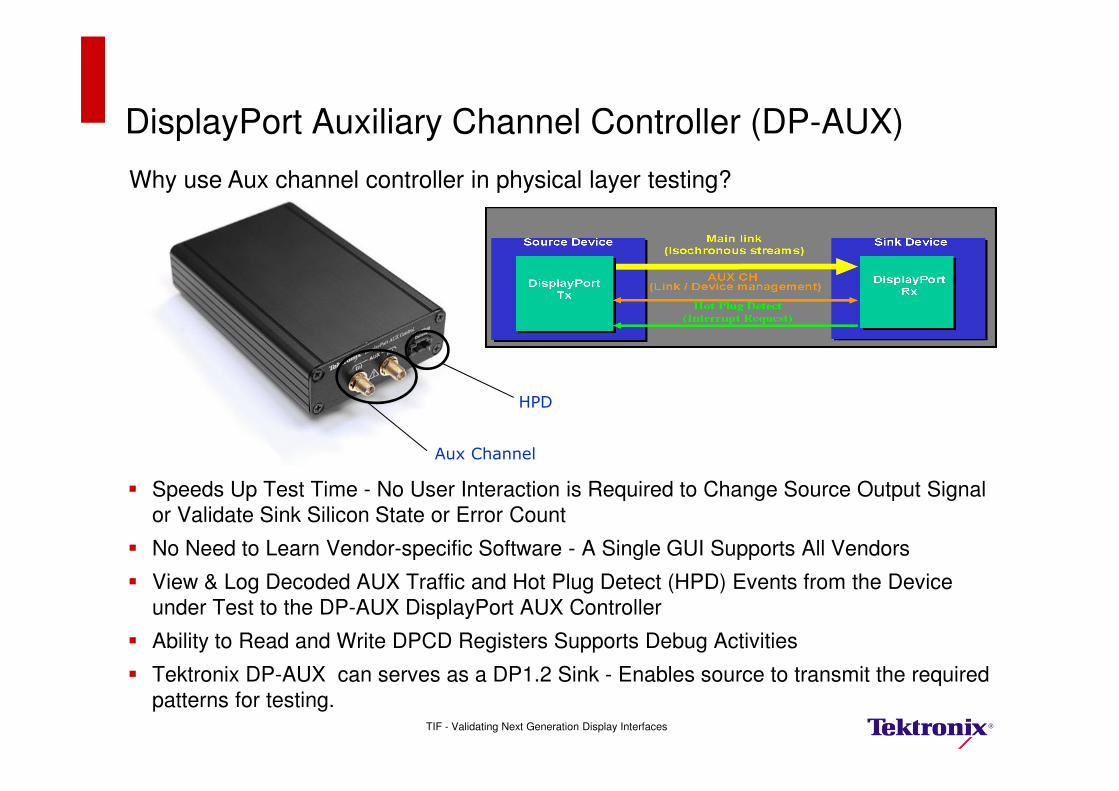
DisplayPort Auxiliary Channel Controller (DP-AUX)
� Speeds Up Test Time - No User Interaction is Required to Change Source Output Signal
or Validate Sink Silicon State or Error Count
� No Need to Learn Vendor-specific Software - A Single GUI Supports All Vendors
� View & Log Decoded AUX Traffic and Hot Plug Detect (HPD) Events from the Device
under Test to the DP-AUX DisplayPort AUX Controller
� Ability to Read and Write DPCD Registers Supports Debug Activities
� Tektronix DP-AUX can serves as a DP1.2 Sink - Enables source to transmit the required
patterns for testing.
Aux Channel
HPD
Why use Aux channel controller in physical layer testing?
TIF - Validating Next Generation Display Interfaces
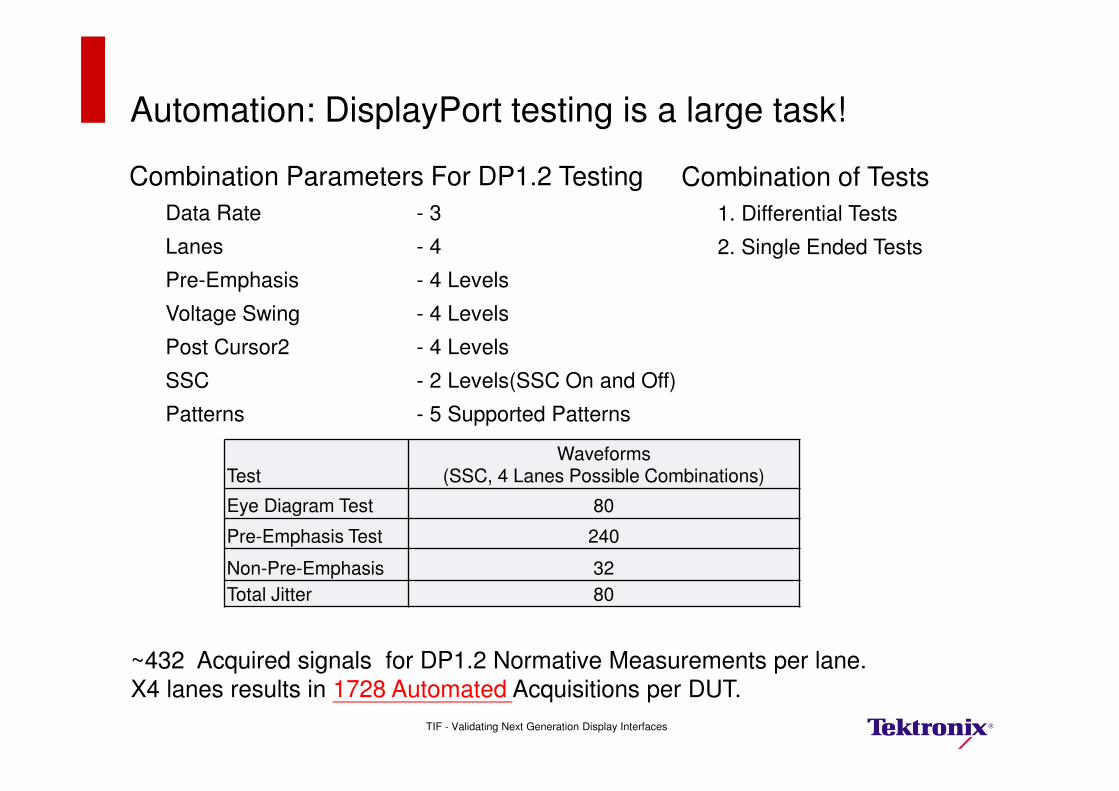
Automation: DisplayPort testing is a large task!
Combination Parameters For DP1.2 Testing
Data Rate - 3
Lanes - 4
Pre-Emphasis - 4 Levels
Voltage Swing - 4 Levels
Post Cursor2 - 4 Levels
SSC - 2 Levels(SSC On and Off)
Patterns - 5 Supported Patterns
Combination of Tests
1. Differential Tests
2. Single Ended Tests
TestWaveforms
(SSC, 4 Lanes Possible Combinations)
Eye Diagram Test 80
Pre-Emphasis Test 240
Non-Pre-Emphasis 32
Total Jitter 80
~432 Acquired signals for DP1.2 Normative Measurements per lane. X4 lanes results in 1728 Automated Acquisitions per DUT.
TIF - Validating Next Generation Display Interfaces
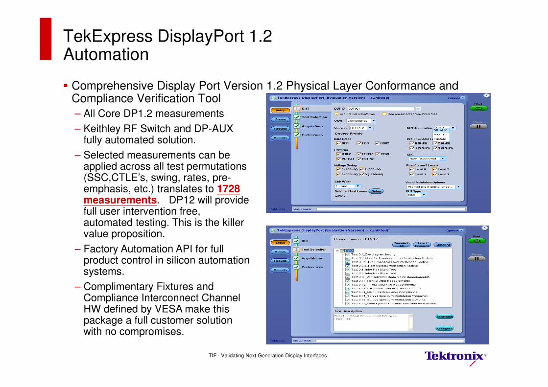
TekExpress DisplayPort 1.2 Automation
� Comprehensive Display Port Version 1.2 Physical Layer Conformance and Compliance Verification Tool
– All Core DP1.2 measurements
– Keithley RF Switch and DP-AUX fully automated solution.
– Selected measurements can be applied across all test permutations (SSC,CTLE’s, swing, rates, pre-emphasis, etc.) translates to 1728measurements. DP12 will provide full user intervention free, automated testing. This is the killer value proposition.
– Factory Automation API for full product control in silicon automation systems.
– Complimentary Fixtures and Compliance Interconnect Channel HW defined by VESA make this package a full customer solution with no compromises.
TIF - Validating Next Generation Display Interfaces
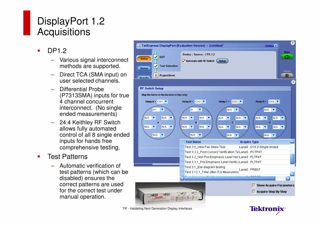
DisplayPort 1.2 Acquisitions
� DP1.2
– Various signal interconnect methods are supported.
– Direct TCA (SMA input) on user selected channels.
– Differential Probe (P7313SMA) inputs for true 4 channel concurrent interconnect. (No single ended measurements)
– 24:4 Keithley RF Switch allows fully automated control of all 8 single ended inputs for hands free comprehensive testing.
� Test Patterns
– Automatic verification of test patterns (which can be disabled) ensures the correct patterns are used for the correct test under manual operation.
TIF - Validating Next Generation Display Interfaces
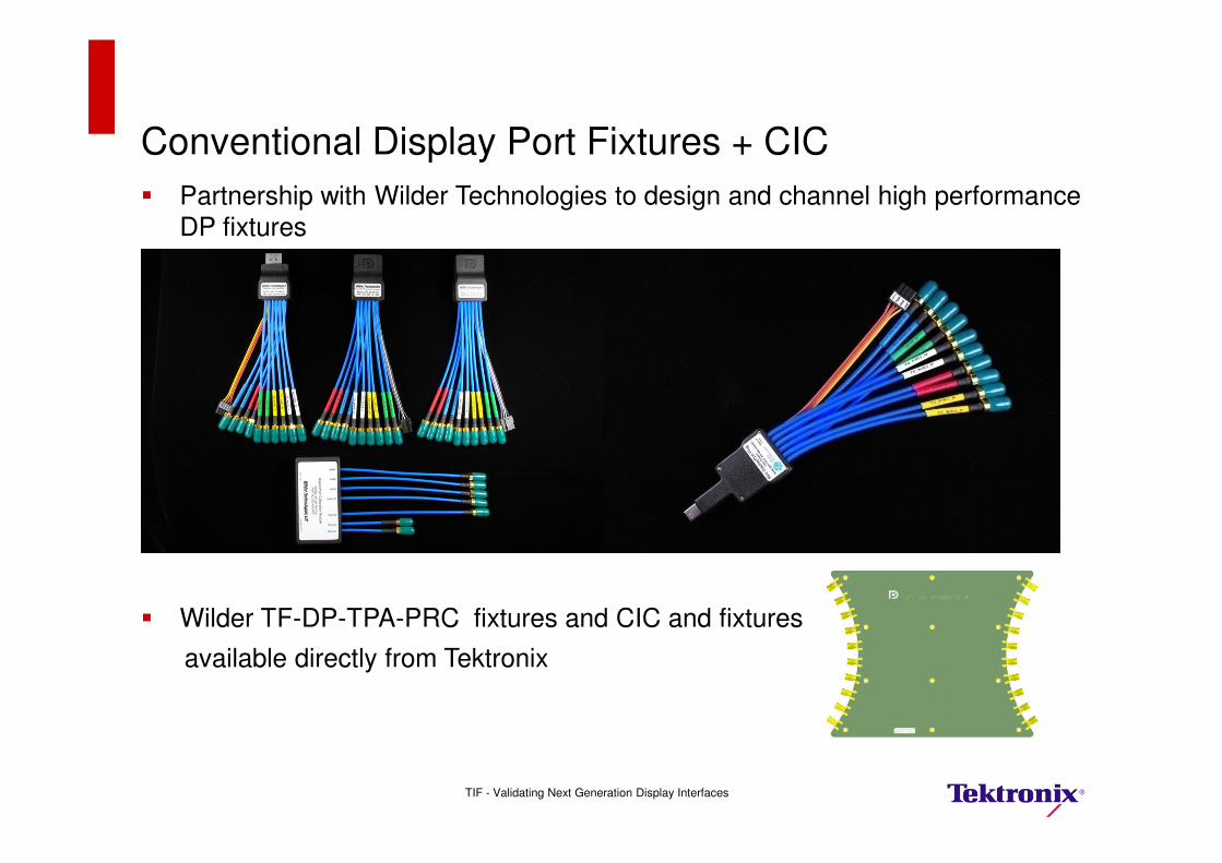
Conventional Display Port Fixtures + CIC
� Partnership with Wilder Technologies to design and channel high performance
DP fixtures
� Wilder TF-DP-TPA-PRC fixtures and CIC and fixtures
available directly from Tektronix
TIF - Validating Next Generation Display Interfaces
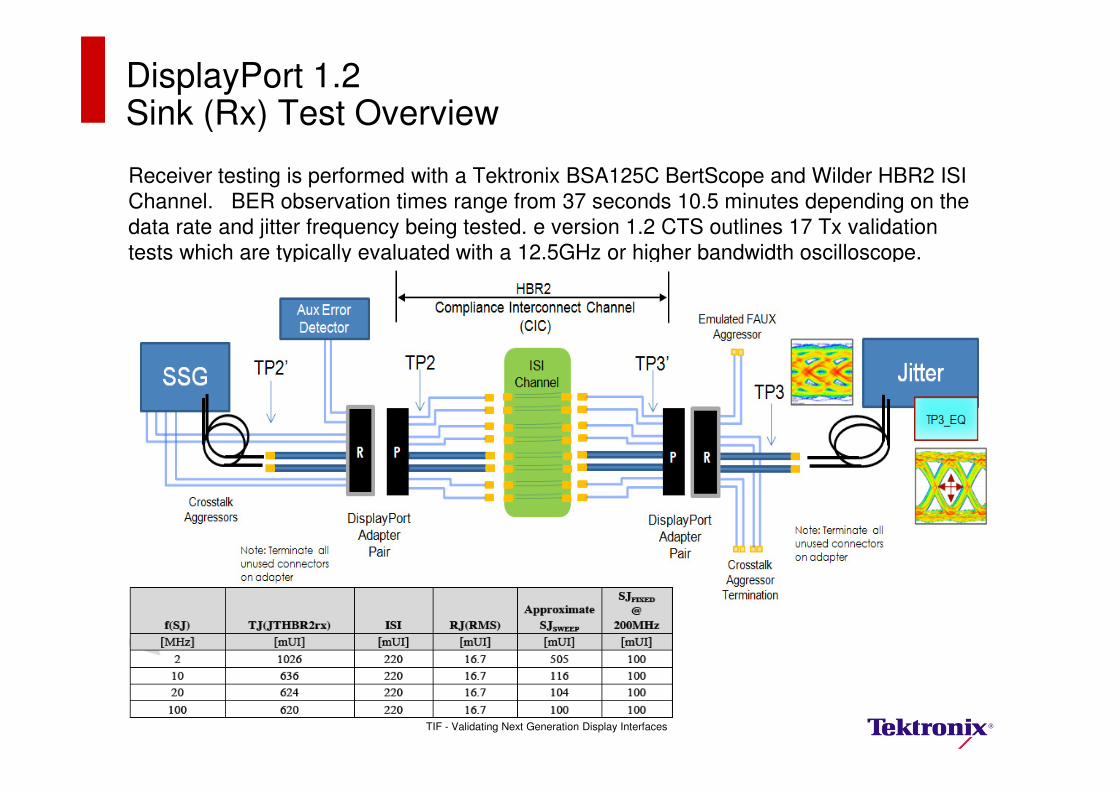
Receiver testing is performed with a Tektronix BSA125C BertScope and Wilder HBR2 ISI
Channel. BER observation times range from 37 seconds 10.5 minutes depending on the
data rate and jitter frequency being tested. e version 1.2 CTS outlines 17 Tx validation
tests which are typically evaluated with a 12.5GHz or higher bandwidth oscilloscope.
DisplayPort 1.2 Sink (Rx) Test Overview
TIF - Validating Next Generation Display Interfaces

Four Principal Test Frequencies at 2, 10, 20 and 100 MHz SJ
DisplayPort 1.2 Sink (Rx) Test Observation Time
TIF - Validating Next Generation Display Interfaces
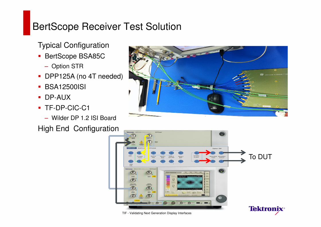
BertScope Receiver Test Solution
Typical Configuration
� BertScope BSA85C
– Option STR
� DPP125A (no 4T needed)
� BSA12500ISI
� DP-AUX
� TF-DP-CIC-C1
– Wilder DP 1.2 ISI Board
High End Configuration
To DUT
TIF - Validating Next Generation Display Interfaces
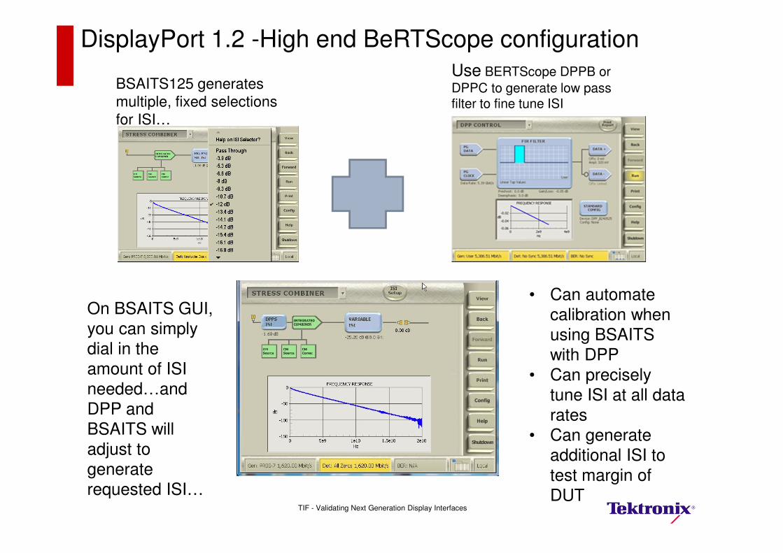
BSAITS125 generates
multiple, fixed selections
for ISI…
Use BERTScope DPPB or
DPPC to generate low pass filter to fine tune ISI
On BSAITS GUI,
you can simply
dial in the amount of ISI
needed…and
DPP and
BSAITS will adjust to
generate requested ISI…
• Can automate calibration when
using BSAITS
with DPP• Can precisely
tune ISI at all data
rates
• Can generate additional ISI to test margin of DUT
DisplayPort 1.2 -High end BeRTScope configuration
TIF - Validating Next Generation Display Interfaces
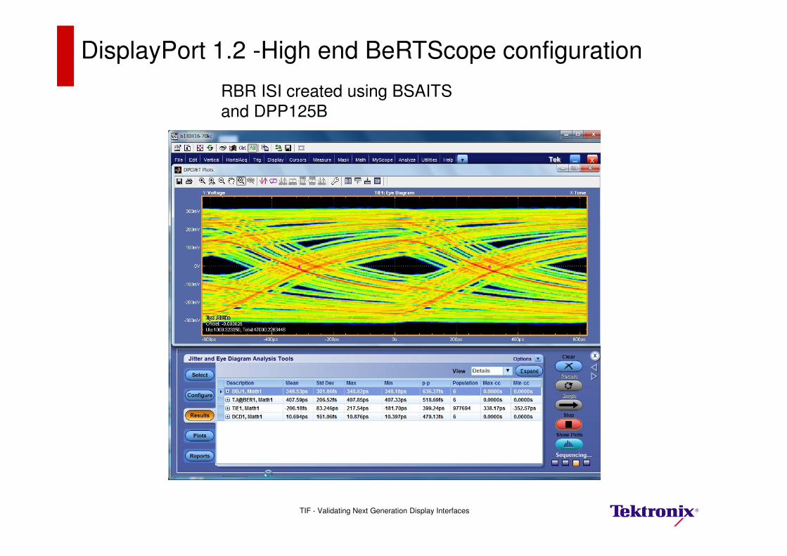
RBR ISI created using BSAITS
and DPP125B
DisplayPort 1.2 -High end BeRTScope configuration
TIF - Validating Next Generation Display Interfaces
Embedded Display Port-eDP
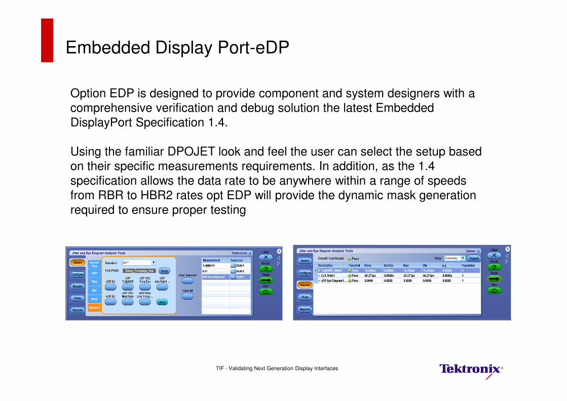
Option EDP is designed to provide component and system designers with a comprehensive verification and debug solution the latest Embedded
DisplayPort Specification 1.4.
Using the familiar DPOJET look and feel the user can select the setup based
on their specific measurements requirements. In addition, as the 1.4 specification allows the data rate to be anywhere within a range of speeds
from RBR to HBR2 rates opt EDP will provide the dynamic mask generation
required to ensure proper testing
TIF - Validating Next Generation Display Interfaces
Embedded Display Port-eDP Typical connection
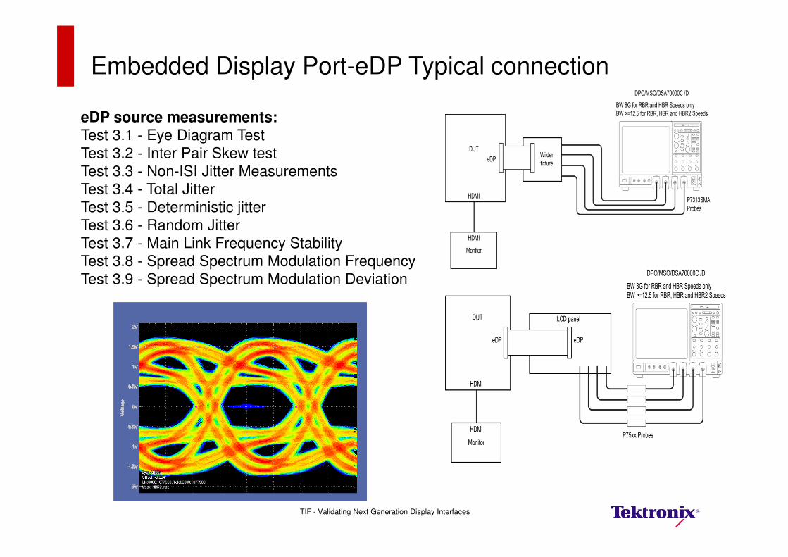
eDP source measurements:
Test 3.1 - Eye Diagram Test
Test 3.2 - Inter Pair Skew test
Test 3.3 - Non-ISI Jitter Measurements
Test 3.4 - Total Jitter
Test 3.5 - Deterministic jitter
Test 3.6 - Random Jitter
Test 3.7 - Main Link Frequency Stability
Test 3.8 - Spread Spectrum Modulation Frequency
Test 3.9 - Spread Spectrum Modulation Deviation
TIF - Validating Next Generation Display Interfaces
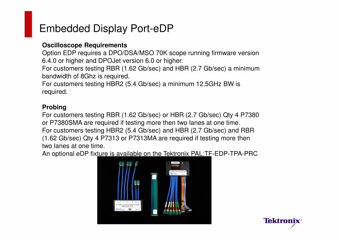
Oscilloscope Requirements
Option EDP requires a DPO/DSA/MSO 70K scope running firmware version
6.4.0 or higher and DPOJet version 6.0 or higher.
For customers testing RBR (1.62 Gb/sec) and HBR (2.7 Gb/sec) a minimum
bandwidth of 8Ghz is required.
For customers testing HBR2 (5.4 Gb/sec) a minimum 12.5GHz BW is
required.
Probing
For customers testing RBR (1.62 Gb/sec) or HBR (2.7 Gb/sec) Qty 4 P7380
or P7380SMA are required if testing more then two lanes at one time.
For customers testing HBR2 (5.4 Gb/sec) and HBR (2.7 Gb/sec) and RBR
(1.62 Gb/sec) Qty 4 P7313 or P7313MA are required if testing more then
two lanes at one time.
An optional eDP fixture is available on the Tektronix PAL:TF-EDP-TPA-PRC
Embedded Display Port-eDP
TIF - Validating Next Generation Display Interfaces
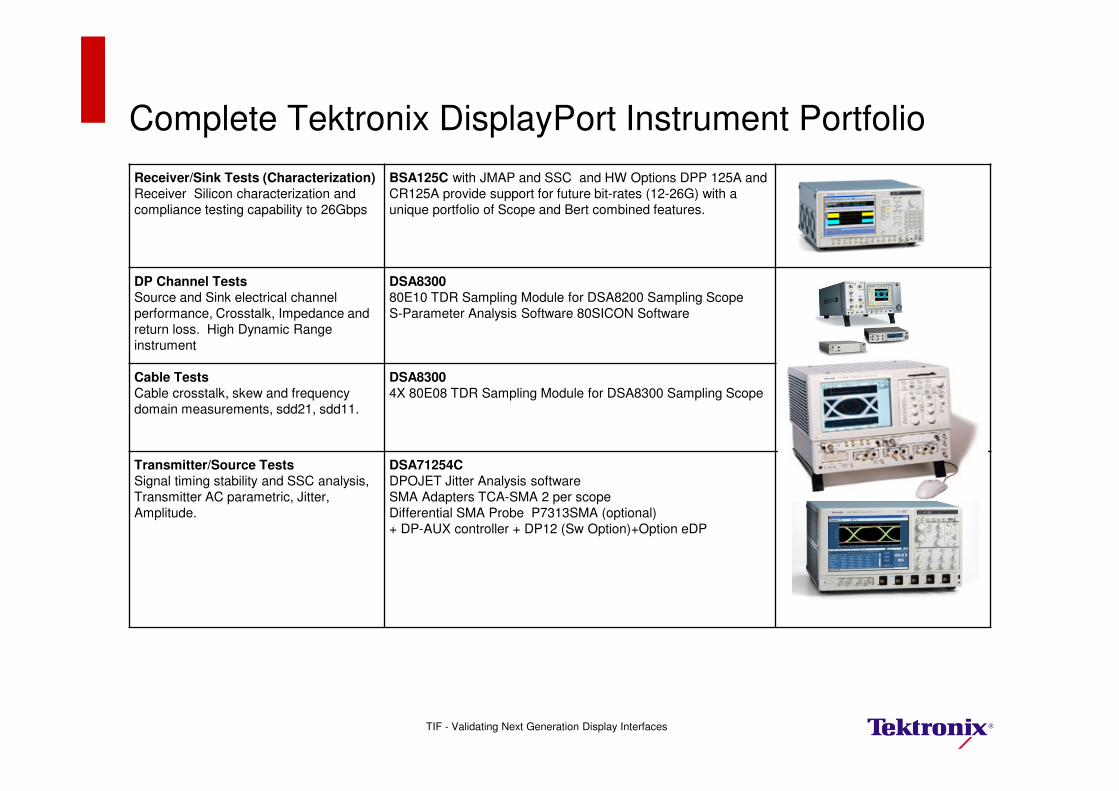
Receiver/Sink Tests (Characterization)
Receiver Silicon characterization and
compliance testing capability to 26Gbps
BSA125C with JMAP and SSC and HW Options DPP 125A and
CR125A provide support for future bit-rates (12-26G) with a
unique portfolio of Scope and Bert combined features.
DP Channel Tests
Source and Sink electrical channel
performance, Crosstalk, Impedance and
return loss. High Dynamic Range
instrument
DSA8300
80E10 TDR Sampling Module for DSA8200 Sampling Scope
S-Parameter Analysis Software 80SICON Software
Cable Tests
Cable crosstalk, skew and frequency
domain measurements, sdd21, sdd11.
DSA8300
4X 80E08 TDR Sampling Module for DSA8300 Sampling Scope
Transmitter/Source Tests
Signal timing stability and SSC analysis,
Transmitter AC parametric, Jitter,
Amplitude.
DSA71254C
DPOJET Jitter Analysis software
SMA Adapters TCA-SMA 2 per scope
Differential SMA Probe P7313SMA (optional)
+ DP-AUX controller + DP12 (Sw Option)+Option eDP
Complete Tektronix DisplayPort Instrument Portfolio
TIF - Validating Next Generation Display Interfaces
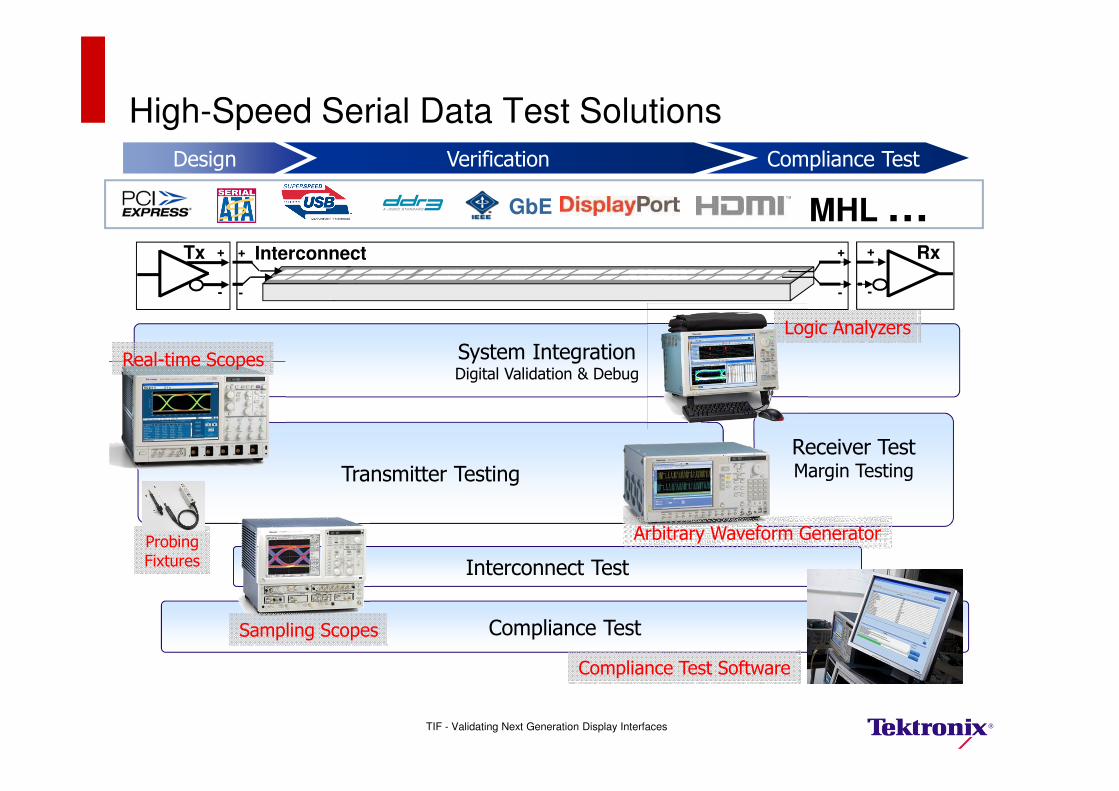
High-Speed Serial Data Test Solutions
Design Verification Compliance Test
Interconnect Test
InterconnectTx +
-
+
-
+
-
+
-
Rx
Transmitter Testing
System IntegrationDigital Validation & Debug
Receiver TestMargin Testing
Compliance Test
Real-time Scopes
Sampling Scopes
Arbitrary Waveform Generator
Logic Analyzers
Compliance Test Software
ProbingFixtures
GbE MHL …
TIF - Validating Next Generation Display Interfaces
TIF - Validating Next Generation Display Interfaces
Thank You for Attending