Embed Size (px)
Citation preview

Model: 3NB-1300C
1300 HP Triplex Single Acting Mud Pump
Serial No.:2006.03.015
Instruction Manual
LANZHOU PETROLEUM & CHEMICAL MACHINERY WORKS
February, 2005

CONTENTS
Preface
1. Technical Specifications
2. Design features
3. Installation
4. Operation
5. Maintenance
6. Assembling & dismantling
7. Storage
8. Restarting after storage
9. Special tools along with the pump
10. Bearings list
11. Tightening moment for the main positions
1

Preface
In order to help the users to get familiar with the design features and performance of
the slush pumps of our make, this manual gives a detailed description of the technical
specifications, construction, installation, operation, maintenance, storage, etc. of the
3NB1300C triplex slush pumps for the guidance of the operators and repairmen in
their work.
Reading this manual carefully and abiding by the requirements specified herein are of
importance to ensuring a normal operation of the pumps and extending their service
life.
The front and rear sides, the right and left sides of the pump are determined by
viewing the pump from the back of the power end, looking toward the fluid end.
2

1. Technical specifications
Type
Parameter 3NB1300C
Input power rating (KW) 956 (1300HP)
Rated pump speed (SPM) 120
Stroke (mm) 305
Gear ratio 3.81
Rated speed of transmission shaft (RPM) 457
Max. working pressure (MPa) 34.3 (5000PSI)
Valve size (API) 7#
Max. liner diameter (mm) φ190
Max. displacement (l/s) 46.6
Max. liner pressure (MPa) 18.4 (2500PSI)
Diameter of suction pipe (mm) 305 (12”)
Diameter of discharge pipe (mm) 100 (4”)
Overall dimensions 5010x1942x1918mm
Weight (ton) 23
3

3NB1300C Pump Performance Data
Diameter of liner mm φ190 φ180 φ170 φ160 φ150 φ140 φ130
PSI 2000 2500 3000 3800 4000 4500 5000
Discharge pressure
MPa 16.6 18.4 20.7 23.4 26.6 30.5 34.3
Pump speed
Input power Output power
SPM KW HP KW HP
Displacement (litres per second)
1 7.96 10.80 7.171 9.75 0.433 0.388 0.345 0.306 0.269 0.235 0.202
50 398.4 542 359 487.5 21.6 19.4 17.25 15.3 13.45 11.75 10.1
60 478 650 430 585 26 23.3 20.8 18.4 16.2 14.1 12.2
70 558 758 502 683 30.3 27.2 24.2 21.5 18.8 16.5 14.2
80 637 867 574 780 34.6 31 27.6 24.2 21.5 18.8 16.2
90 717 975 645 878 38.9 35.0 31.1 27.6 24.2 21.2 18.2
100 797 1083 717 975 43.3 38.8 34.3 30.6 26.9 23.5 20.25
110 876 1191 789 1073 47.6 42.7 38.0 33.7 29.6 25.9 22.3
120 956 1300 860 1170 51.9 46.6 41.5 36.8 32.3 28.2 24.3
Note: Based on 90% mechanical efficiency and 100% volumetric efficiency
4
2. Design features
2.1 The power end
2.1.1 The pump frame is of welded steel – plate construction. The bearing housings of the
crankshaft and the transmission shaft are made of steel castings and are welded to
the frame after rough – machined. They are stress – relieved after welded.
2.1.2 The crankshaft is a hollow steel casting.
2.1.3 The herringbone gear ring and pinion are composed of helical gears in pairs
respectively.
2.1.4 The crosshead is a one – piece casting and runs directly in the guides.
2.1.5 All the bearings, crossheads and guides are splash – lubricated. At suitable locations
there are oil wipers and troughs provided to ensure a well – distributed lubrication.
2.1.6 The transmission shaft is equipped with single – row radial short – roller bearings.
2.1.7 The main bearings are double – row radial spherical – roller bearings.
2.1.8 The crosshead is equipped with long – roller bearings.
2.1.9 The big end of the connecting rod runs in radial roller bearing.
2.2 The fluid end
2.2.1 The fluid end is composed of three fluid modules (cylinders), each of which is a
sectional and communicating construction. The suction and discharge are
accomplished by suction and discharge pipes. The suction and discharge valves are
vertically aligned with each other to minimize the volumetric clearance.
2.2.2 There is clamp connection between the piston rod and the intermediate rod, which
facilitates the services of these parts.
2.2.3 The piston liner is attached to the liner seat with a buttress – threaded retainer.
2.2.4 The threaded cover of the valve box is attached to the threaded ring with buttress
threads, which facilitates the services of them. The threaded ring is fastened to the
fluid module with studs, which facilitates the machining and servicing of the fluid
module.
2.2.5 The taper of the valve seat is 1:6. The bottom of the seat is provided with a shoulder to
be suitable for high operating pressure.
5
2.2.6 The piston rod conforms to SY5138-86. The piston is fastened with M39x3 locknut and
is lubricated and cooled by the water or the water with inhibitor supplied by a
centrifugal spray pump.
2.2.7 There are six sizes of liners with an increment of 10mm in I.D. All these liners are the
same in O.D.
2.2.8 There are two types of liners: high-grade liner and plain liner. The high – grade liner is
made of carbon steel as a base metal which is casted or inserted with high – chrome
alloy – steel to ensure wearability. The plain liner is made of low – carbon steel which
is carburized and quenched inside to enhance the surface hardness.
2.2.9 There are suction inlets in front of and on both sides of the pump, which are connected
to the suction manifold. The three suction flanges are of 12”ASAB16.5-150PSI or
10”ASAB16.5-150PSI.
2.2.10 The flanges of discharge pipe and five-way joint are of 4”API-5000PSI6B. The seal
rings here are API’s R39.
2.2.11 The discharge pulsation dampener is spherical and pre – pressured. Its Max. working
pressure is 350kg/cm2, and volume is 75 litres (20 gallons). The pulsation dampener
is connected to the air filler and to the pressure gauge, using 3/4” – 14NPT and 1/4” –
18NPT respectively.
2.2.12 The suction pulsation dampener is of rubber – hose type and pre – pressured and
connected with the flanges of the 12” and 10”ASAB16.5-150PSI.
2.2.13 It is advisable to equip a charging pump during operation to improve the suction
performance and raise the efficiency of the slush pump.
2.2.14 It is advisable to equip a spray pump during operation to cool the pistons and liners so
as to extend their service life.
2.3 Accessories
Complete set of special tools for major locations of the pump will be provided along with
the slush pump to facilitate the services and replacement of expendable parts.
3. Installation
Prior to installation, a proper layout plan shall be prepared to indicate the position of the
slush pump, charging pump and spray pump as well as the disposition of the suction and
discharge manifolds.
6

The slush pump shall be provided with a centrifugal charging pump to enhance the pump
efficiency. There shall be a metallic slush sump above the ground, and the suction
manifold shall be as short as possible to improve the suction condition.
3.1 Foundation
The slush pump shall be set on a level concrete foundation and the same oil level shall be
kept in the left and right oil troughs of the power end so as to assure satisfactory
distribution of oil to all parts to be lubricated. Especially in drilling vessels, the slush pump
shall be properly leveled over the whole length. With the slush pump leveled, all the
anchor bolts shall be tightened uniformly around the main base to secure the pump base
against deformation, especially in case of belt or chain transmission, and some plates or
bars may be used to fix the pump and prevent the pump from displacement.
3.2 Transmissions
A belt or chain transmission can be used for the slush pump. According to the actual
conditions the driven sheave or sprocket can be located on the left or right side, and the
sheave to drive the spray and charging pumps will be mounted on the other side. The
rotation direction of running centrifugal spray pump or charging pump shall be the same
as the designated directions for both spray and charging pumps otherwise it cannot be
normally operated. The slush pump should be operated at a low speed to improve the
suction condition, realize a smooth operation and prolong the service life of the
expendable parts.
The spray pump or charging pump can be driven directly by an electric motor in proper
direction.
3.3 The suction manifold
The ID of suction piping shall be at least as large as the inlet ID of the pump. Prior to
installation, the suction manifold shall be thoroughly cleaned from inside. After installation,
no leakage should be allowed at any connections. It is advisable to use as few valves or
bends as possible. Always use full-opening valves, such as butterfly valves, and never
use flow-limiting valve which may reduce the efficiency of the pump.
The slush pump should be provided with a charging pump to realize a smooth operation
of the pump and extend the service life of expendable parts.
7

The suction manifold shall be designed to be suitable for “dual” operation, permitting
either “natural” suction or “charged” suction. The piping used for “natural” suction shall be
as short as possible and preferably without bends. A suction pulsation dampener
(desurger) should be connected with suction piping at either type of suction and shall be
mounted as close as possible to the pump inlet.
There shall be a safety valve between the pump inlet and the outlet of the charging pump.
The safety valve shall be adjusted to 5kg/cm2 (70psi). It protects the charging pump from
damage in the event of overpressure occurring in the suction manifold.
3.4 The discharge manifold
According to the field conditions, the discharge manifold can be installed on either the left
or the right side of the pump. The inside diameter of the manifold is 100mm (4”).
A pressure relief valve shall be mounted near the discharge port of the pump to protect
the pump against damage from overpressure. The valve shall be located ahead of any
valve on the discharge manifold. In such a case, any unexpected starting of the pump in
the event of closed valve will not damage to the pump. The discharge piping of relief
valve shall be fastened securely and extended safely into the slush sump to avoid any
accident resulting from high-pressure slush with the relief valve opened.
A pulsation dampener is mounted on the discharge manifold to reduce the fluctuation of
the pressure of discharged fluid.
4. Operation
4.1 Preparations prior to starting
4.1.1 The power end shall be lubricated with #120 extreme – pressure industrial gear – oil of
the sulphur – phosphorus type (or AGMA – recommended Mild EP2) in winter and with
#200 such oil (or EP6) in summer. 3NB1300C with 400 litres. The lubricant shall be
inspected and changed at regular intervals to keep it clean.
4.1.2 Prior to starting a new slush pump or restarting a pump stored for a long time, open
the inspection hole on the pump and fill the pinion and gear oil – trough and the
crosshead oil reservoir with lubricant. Then run the pump by hand for several
revolutions to ensure prompt lubrication of parts with the lubrication spots full of oil.
4.1.3 Water or water – based rust – preventing cooling fluid shall be used to spray – cool the
8
piston liners. The spray pump shall be started earlier than or simultaneously with the
slush pump to avoid overheating of the pistons and liners.
4.1.4 The spray pump can be driven by the transmission (pinion) shaft with belts or directly
by an electric motor. Prior to starting of the spray pump, it shall be fully filled with fluid
to prevent cavitations. With the spray pump running, some 10 drops per minute of fluid
leaking is permissible at the seals to help improve the lubrication of packing.
4.1.5 Inspect the pistons, liners and valves to see that they are assembled properly. Inspect
also the discharge manifold to see that the valve thereon is open.
4.1.6 Open the valve on the suction manifold and start the centrifugal charging pump earlier
than or simultaneously with the slush pump. The charging pump shall run in a
condition without cavitations.
4.1.7 Prior to starting of the slush pump, it is advisable to fully fill the fluid modules with
drilling fluid or water to prevent cavitations. No air cavity can be eliminated under
pressure. For this purpose, open the valve towards the slush pump and run the pump
in a condition of “small circulation” until air is removed so as to ensure smooth
operation of the slush pump and to extend the service life of the valves and pistons.
4.1.8 Inspect that the safety pin of relief valve is inserted into the pin hole which has the
relevant pressure with the liner.
4.2 Some points for attention after starting
4.2.1 Increase RPM of the pump gradually so that the fluid speed in the suction manifold
may keep pace with the piston speed to prevent cavitations.
4.2.2 In the case of “natural suction”, the top speed of the slush pump is determined by an
abundant suction of the pump in its suction stroke and is different from condition to
condition, depending upon the design of the suction manifold and upon the effective
head and upon the conditions of the drilling fluid such as its specific gravity, viscosity
and air content. The operator can judge from the pump noise whether cavitations or
poor suction occurs and can take action promptly.
4.2.3 For the charged suction, with the slush pump started, adjust the discharge valve of the
charging pump to ensure adequate charging.
4.2.4 If the slush pump is equipped with a suction desurger, the latter shall be filled with air
9

prior to starting of the slush pump (some 0.7kg/cm2 or 10psi). In the case of a
horizontal pre-pressing desurger, with the slush pump running, the diaphragm position
can be observed through the window of the desurger. The diaphragm can be
positioned between the middle and botton lines to undulate by increasing or reducing
the internal pressure of the desurger.
4.2.5 Inspect the bearings, crossheads, guides, etc. for overheating or other abnormalities.
Generally, the oil temperature shall not exceed 80℃.
5. Maintenance
5.1 Daily maintenance
5.1.1 The oil level at the power end shall be inspected once a shift with the slush pump
stopped. In the case of chain transmission, the oil level in the chain box shall be
inspected.
5.1.2 The operating conditions of the pistons and liners shall be frequently observed. A
slight leakage due to by – passing is normal and is unlikely to indicate any wear of the
pistons or liners. However, no leakage in excess is permissible.
5.1.3 The cooling fluid for the pistons and liners shall be frequently inspected, refilled and, if
necessary, changed if it’s dirty. Dirty coolant will increase the wear of the pump, and
shorten its service life.
5.1.4 The spray pipes for the liners shall be inspected once a day and, if necessary, dredged
to ensure adequate cooling and lubrication of the pistons and liners.
5.1.5 After the first hours of operation following installation, recheck the piston rod clamp for
proper tightness. The clamp with dirty or foreign matters will become loose and, if
necessary, need retightening to prevent early damage to the pump parts due to
operation with loose connections.
5.1.6 Daily slacken the piston rod clamp and turn the piston about one quarter of a
revolution and then retighten them. This will result in well – distributed wear of the
pistons to ensure a long service lift of the pistons and liners.
5.1.7 When the slush pump is equipped with a suction desurger, it is advisable to check its
internal pressure once a day to ensure that its air filling meets the specified
requirement.
5.1.8 Check the pressure of the discharge pulsation dampener to ensure that its air filling
10

meets the specified requirement.
5.2 Weekly maintenance
5.2.1 Remove the threaded cover of the valve and clear away any sludges or dirts from the
threads of the threaded over and ring, and then coat them with thread lubricant to
prevent its wear, scratch or jam. (Lead – base lubricant for thread is recommended).
5.2.2 Check the valve stem guide bush for wear and, if worn evidently, change it. Any guide
bush out of round or oval bush will badly guide the valve stem and speed up the valve
wear.
5.2.3 Check the valve and its seat for wear. Any worn or damaged valve seat shall be
changed. Retighten the loosened valve nut.
5.2.4 Check the pistons and liners and change the worn or damaged piston or liner.
5.2.5 Change worn or damaged lock nut of the piston. The lock nut shall be changed if its
locking fibre does not function.
5.3 Monthly maintenance
5.3.1 The oil trough and settling chamber (under the crosshead) at the power end shall be
emptied of dirty oil every six months and refilled with new clean oil.
5.3.2 Inspect the gaskets and seal rings at the power end and change damaged ones.
Retighten the loose screws, especially the screws which fasten the sheaves or
sprockets.
5.3.3 Check the clearance between the crosshead and guides every six months and adjust
too large clearance.
5.3.4 Check all the studs and nuts at the fluid end for rightness, including those between
threaded ring and fluid module, between module and frame and between liner bush
and module.
5.3.5 The magnets at bearing’s oil troughs to collect iron particles at the power end shall be
cleaned once a month.
5.4 Yearly maintenance
Check once a year or every two years all the bearings of the crankshaft, connecting rods,
transmission shaft, crossheads and its guide, for looseness. If necessary, carefully and
thoroughly inspect the slush pump and take corrective action.
6. Assembling & dismantling
11
6.1 Assembling of the power end
6.1.1 Mount the transmission shaft assembly into the frame from the right or left side with
the pinion and gear located to the right of the frame’s centerline. Make sure that the oil
hole of the bearing support is aligned with that of the retaining plate and is located
below the horizontal centerline of the shaft on the side toward the back of the pump.
When mounting the oil seals of the bearing’s retainers of the transmission shaft, care
shall be taken not to damage their sealing lips.
6.1.2 Fasten the ring gear to the crankshaft with screws. Mount the inner races of the
bearings at the big end of the connecting rods with shims thickness which equals the
thickness measured minus 0.05-0.15mm. Mount their outer races with shim thickness
which equals the difference between the width of the outer race and that of the
connecting rod minus 0.08-0.18mm. The shim thickness for the crosshead pin is equal
to the actual clearance minus 0.05-0.15mm. The retainers and the main bearings are
not to be mounted yet.
6.1.3 Mount the guides. Measure out the diameters of the guides and crosshead
respectively and then adjust the guides location with shims. The clearance between
the guides and crosshead shall be within 0.25-0.5mm. The lower guide shall be
fastened with a seal ring added to prevent oil leakage.
6.1.4 Using a crane, put the crankshaft assembly into the frame inside the main bearing
support. Mount the heated bearing and its capsule onto the crankshaft against its
shoulder and press the bearing with retainer. Make sure that the oil hole ZG 1/2” is
situated above the horizontal centerline of the cankshaft on the side toward the back of
the pump. Fasten the bearing cover with two nuts.
6.1.5 With the middle crosshead pressed, mount the right and lift crossheads’ pins and
press them with the retainers and screws. The three connecting rods centerlines of the
crankshaft shall be aligned with those of the holes for the guides on the frame
respectively.
6.1.6 With the main bearings cooled, tightly press the inner races of the bearings with the
retainers.
6.1.7 Mount the oil troughs and oil wipers. The clearance between the oil wiper and pinion or
12
gear shall be as small as possible, but no touch is permissible. The oil wipers and oil
troughs shall be tightened securely with screws. With the adjustment finished, they
shall be welded together.
6.1.8 Adjust the pinion on the transmission shaft against the gear on the crankshaft and then
mount the bearing covers and other parts.
6.1.9 Mount the middle crosshead to the small end of the connecting rod, and then mount
the right and left crossheads and small end of connecting rod thereto.
6.1.10 Mount the intermediate rods and their seal rings successively.
6.2 Dismantling of the power end
6.2.1 Remove the intermediate rod, its seals and crosshead’s oil retainer. Care must be
taken that the base – plates for seals of the intermediate rods are not interchangeable.
6.2.2 Remove the crosshead pin retainers. Pull out the right and left crosshead pins with the
help of the threaded holes on the pins. The right and left crossheads can be taken out
of the liner chamber. The middle crosshead can be either taken out of the liner
chamber with its pin pulled out, or taken along with the crankshaft and connecting rod
without pulling its pin out.
6.2.3 Remove the cover of the pump and unscrew the retainers of the bearing supports.
Take out the upper cap of the bearing supports.
6.2.4 Remove the lubrication manifolds, oil troughs and oil wipers.
6.2.5 With the main bearings removed, take out the crankshaft – connecting rod assembly.
On account of its heavy weight, handle it with care to prevent damage to some parts
due to bumping.
6.3 Assembling of the fluid end
6.3.1 Fluid modules (cylinders)
a) Mount the three assembled fluid modules on the frame and screw them on for the moment.
Then tighten the nuts connecting the fluid modules and the frame and also the nuts for the
liner bushes.
b) Mount the greased gaskets into the counterbores located on the module side looking
toward the frame and then mount the wear plates thereon.
c) Prior to mounting the discharge manifold, clean out the locations concerned of three
13
modules and mount the seal rings thereon. Clean out the three planes of the discharge
manifold and screw them onto the modules.
d) Mount the suction manifold onto the fluid modules.
6.3.2 Pistons and liners
a) Mount the piston onto the piston rod. There is a seal ring between the piston body and the
rod shoulder. The seal ring shall be properly mounted onto the piston body before
mounting the piston onto the piston rod. Then tighten the lock nut. Change the lock nut
timely with damaged threads or malfunctioning fibre, otherwise it will result in damage to
the piston, its rod and liner.
b) Coat the inner surface of the liner and the outer surface of the piston with grease. Then
mount the piston rod assembly into the liner with the end equipped with a seal ring of the
liner and the end of the piston rod equipped with a nut both looking toward the fluid
module. Mount the seal ring into the liner against its shoulder and coat the liner’s outer
surface with grease. It is also advisable to mount the liner first, and then to mount the
piston rod assembly.
c) Coat the wear plate of the fluid module and the inner surface of the liner bush with grease,
and then operate the pump by hand so that the intermediate rod goes to the rear dead –
point. Mount the piston rod assembly into the liner which will touch the wear plate. (The
slush pump is supplied along with a hexagonal joint which can be mounted onto the end of
the pinion shaft so as to operate the pump, using appropriate spanner).
d) Clean the joint surface of the liner’s retainer, coat it with thread lubricant and tighten it.
e) Align the piston rod with the intermediate rod and connect them by means of the piston
rod clamp with its joint surface cleaned and coated with grease. Evenly tighten the screw
of the clamp diagonally.
f) Mount the spray hose.
6.3.3 Valves and valve seats
a) Press the valve rubber securely against the valve body with the nut. The cone surface of
the valve rubber shall project about 0.25-0.5mm over the valve body. Any loose body or
rubber will be quickly damaged by the drilling fluid.
b) The bottom of the valve pot is equipped with a shoulder sealed by the outer cone surface
14

of the valve seat to prevent the valve seat from sinking. The valve pot and the outer cone
of the valve seat shall be cleaned and free of scratches or burrs. Put the valve seat into
the taper bore and hammer it with copper striker to ensure a preliminary sealing.
c) Mount the valve onto the valve seat with the centerline of the valve spring aligned with that
of the valve body.
d) Fasten the guide bush located at the upper section of the valve stem to the valve cover. In
the event of excessively worn bore of the bush or increased clearance between the valve
stem and the guide bush, such a bush shall be changed, otherwise the valve and its seat
will easily be worn.
e) Coat the gasket of the valve cover with grease and mount it onto the cleaned shoulder of
the fluid module. The gasket shall be changed if it is scratched or damaged.
f) Assembly of the suction valves
Place the valve spring and valve on the valve seat. Vertically insert the positioning rack
and then turn it by 90° and push it downwards so as to mount the positioning plate.
Caution: The top of the rack shall be absolutely horizontal, the rack shall be aligned with
the valve stem and spring, otherwise it will be damaged in operation of the slush pump.
g) Screw the threaded cover into the threaded ring. Insert the 0.6 metre iron bar in length into
the hole of the cover and strike 3-4 times it with a 16 lbs hammer in weight so as to tighten
it.
6.4 Dismantling of the fluid end
6.4.1 Prior to dismantling, stop the pump and unpressurize the fluid modules to avert
accidents.
6.4.2 Suction manifold
The suction manifold can be independently removed. However it shall be as seldom
removed as possible.
The gaskets shall preferably be changed therewith.
6.4.3 Suction valve
Remove the threaded cover and the plug of the fluid end. The worn seal ring shall be
removed. Take the positioning plate out of the positioning rack and loosen the latter.
Take it up and turn it by 90° before removing it.
6.4.4 Liner spray
15
Remove the spray hose for piston liner and clean it thoroughly.
6.4.5 Pistons and liners
a) Removal of the piston rod independently
Remove the front threaded cover and suction valve, etc. Operate the pump by hand until
the intermediate rod goes to the front dead – point. Remove the piston rod clamp and
operate the pump backwards. Put a 100mm in thickness wood block between the
intermediate rod and piston rod. Then operate the pump forwards to remove the piston
rod.
b) Removal of the piston along with the liner
Remove the piston rod clamp and liner retainer. Operate the pump by hand until the
intermediate rod goes to the rear dead – point. Put a suitable pry bar between the liner
bush and liner shoulder to pry out the liner, and then remove the piston out of the liner.
6.4.6 Pistons
a) The piston body shall not be removed from the rod if replacement of the piston cup is
needed only. Remove the snap ring and retainer in front of the piston body to take out the
piston cup.
b) If replacement of the piston as a whole is needed, remove the lock nut for the piston and
remove the piston body from the rod. Care must be taken not to damage the seal of the
piston body.
6.4.7 Liner bush
Remove the nuts of the bush by means of the wrench supplied along with the slush
pump. Put an appropriate pad between the liner and retainer and retighten the retainer
to remove the liner bush.
6.4.8 Wear plate and gasket
The wear plate is positioned by the liner bush. With the bush removed, use the two
threaded holes (M10) on the wear plate to remove it, and then remove the gasket.
6.5 Assembling of spray pump and charging pump
6.5.1 The spray pump can be adjusted with shims to ensure its performance. The clearance
between the vane wheel and pump - housing shall be 0.3-0.5mm which has been
16

ensured by the manufacturer in the factory. The outlet of the pump can be moved by
90°, if required.
6.5.2 In order to guarantee the performance of centrifugal charging pump. The clearance
between the vane wheel and the housing of the charging pump shall be adjusted to
0.5-0.7mm which has been ensured by the manufacturer in the factory. The outlet of
the charging pump can be moved by 45°, if required.
7. Storage
7.1 Power end: when the slush pump is to stop working for more than half a month, the fluid
end shall be raised to tilt the pump to the power end. Then empty the oil troughs and the
settling chamber and clean them to store the pump for a long time store. With the oil
drained off, coat all the bearings, machined surfaces and the whole surface of the power
end with anti rust oil.
7.2 Remove the valves, pistons, piston rods and liners, thoroughly clean the inside of the fluid
modules and all the parts, coat all the valves, fluid modules and parts with anti – rust oil.
Rinse out the spray system and liner chamber and fill the spray system with lubricant.
7.3 Inspect the slush pump once a month. Rotate the pinion and gear. If necessary, recoat
them with anti – rust oil.
8. Restarting after storage
When restarting a pump stored for some time, whether a pump used in the field or a new
pump received from the manufacturer, it is advisable to carefully inspect it for fitting
conditions and for any damage of components. Failure to bide by the following
requirements will result in serious consequences.
8.1 Open the covers of the power end and the fluid end. Carefully inspect and thoroughly
clean all the components and machined surface. Check all the bearings for cleanness and
good conditions. Fill the power end with lubricant to the level required. Fill the oil –
distributing grooves with lubricant so that the lubricant may reach all the bearings.
8.2 Inspect all the components of the fluid end, especially valves, pistons, liners, etc. to make
sure that they are properly assembled and in good conditions. Tighten the screws, nuts,
studs and movable joints securely.
17
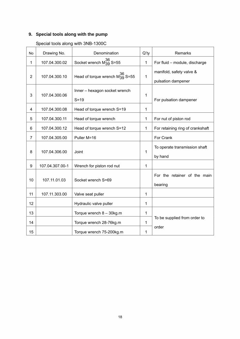
9. Special tools along with the pump
Special tools along with 3NB-1300C
No Drawing No. Denomination Q’ty Remarks
1 107.04.300.02 Socket wrench M3639 S=55 1
2 107.04.300.10 Head of torque wrench M3639 S=55 1
For fluid – module, discharge
manifold, safety valve &
pulsation dampener
3 107.04.300.06 Inner – hexagon socket wrench
S=19 1
4 107.04.300.08 Head of torque wrench S=19 1
For pulsation dampener
5 107.04.300.11 Head of torque wrench 1 For nut of piston rod
6 107.04.300.12 Head of torque wrench S=12 1 For retaining ring of crankshaft
7 107.04.305.00 Puller M=16 For Crank
8 107.04.306.00 Joint 1 To operate transmission shaft
by hand
9 107.04.307.00-1 Wrench for piston rod nut 1
10 107.11.01.03 Socket wrench S=69 For the retainer of the main
bearing
11 107.11.303.00 Valve seat puller 1
12 Hydraulic valve puller 1
13 Torque wrench 8 – 30kg.m 1
14 Torque wrench 28-76kg.m 1
15 Torque wrench 75-200kg.m 1
To be supplied from order to
order
18
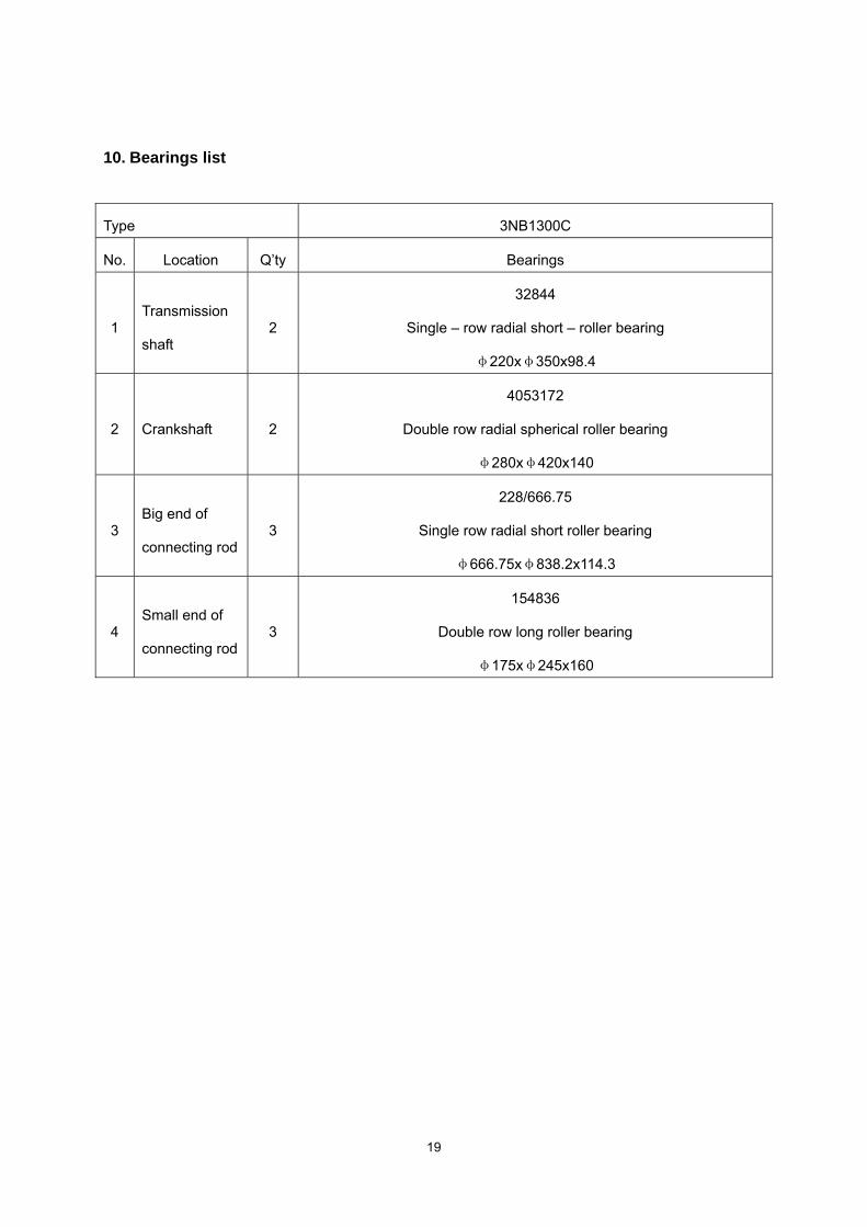
10. Bearings list
Type 3NB1300C
No. Location Q’ty Bearings
1 Transmission
shaft 2
32844
Single – row radial short – roller bearing
φ220xφ350x98.4
2 Crankshaft 2
4053172
Double row radial spherical roller bearing
φ280xφ420x140
3 Big end of
connecting rod 3
228/666.75
Single row radial short roller bearing
φ666.75xφ838.2x114.3
4 Small end of
connecting rod 3
154836
Double row long roller bearing
φ175xφ245x160
19
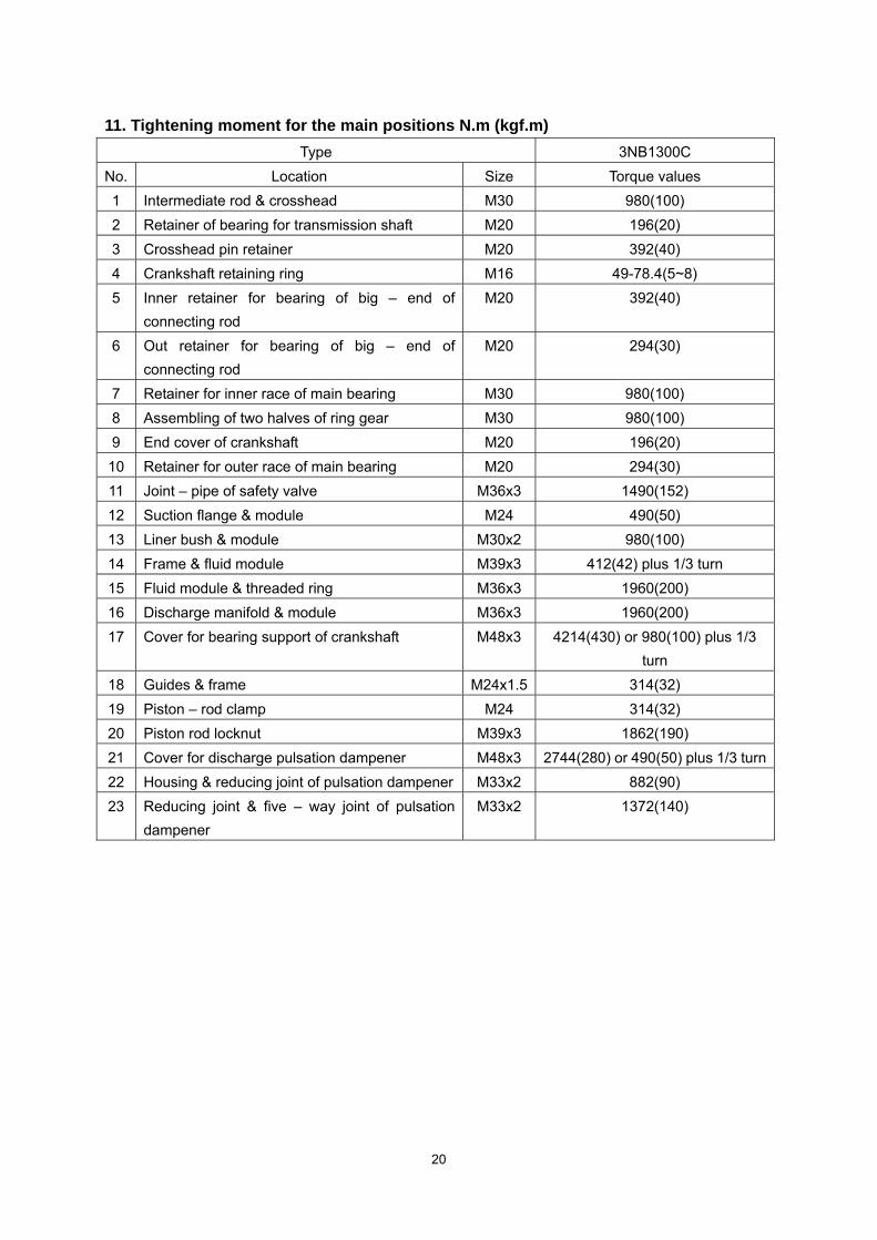
11. Tightening moment for the main positions N.m (kgf.m) Type 3NB1300C
No. Location Size Torque values 1 Intermediate rod & crosshead M30 980(100) 2 Retainer of bearing for transmission shaft M20 196(20) 3 Crosshead pin retainer M20 392(40) 4 Crankshaft retaining ring M16 49-78.4(5~8) 5 Inner retainer for bearing of big – end of
connecting rod M20 392(40)
6 Out retainer for bearing of big – end of connecting rod
M20 294(30)
7 Retainer for inner race of main bearing M30 980(100) 8 Assembling of two halves of ring gear M30 980(100) 9 End cover of crankshaft M20 196(20)
10 Retainer for outer race of main bearing M20 294(30) 11 Joint – pipe of safety valve M36x3 1490(152) 12 Suction flange & module M24 490(50) 13 Liner bush & module M30x2 980(100) 14 Frame & fluid module M39x3 412(42) plus 1/3 turn 15 Fluid module & threaded ring M36x3 1960(200) 16 Discharge manifold & module M36x3 1960(200) 17 Cover for bearing support of crankshaft M48x3 4214(430) or 980(100) plus 1/3
turn 18 Guides & frame M24x1.5 314(32) 19 Piston – rod clamp M24 314(32) 20 Piston rod locknut M39x3 1862(190) 21 Cover for discharge pulsation dampener M48x3 2744(280) or 490(50) plus 1/3 turn22 Housing & reducing joint of pulsation dampener M33x2 882(90) 23 Reducing joint & five – way joint of pulsation
dampener M33x2 1372(140)
20


![ARTICLE IN PRESS - · PDF fileaDepartment of Physics, Lanzhou University, 730000 Lanzhou, ... [1–3]. They have been used in solar cells, ... in this paper we tried to perform the](https://img.pdfslide.net/doc/110x75/5ab1e20a7f8b9a6b468d0f9f/article-in-press-of-physics-lanzhou-university-730000-lanzhou-13.jpg)


![Is NetTraveler APT managed by PLA Military Camp in Lanzhou [China] ???](https://img.pdfslide.net/doc/110x75/54b731334a795912438b4583/is-nettraveler-apt-managed-by-pla-military-camp-in-lanzhou-china-.jpg)