Embed Size (px)
Citation preview
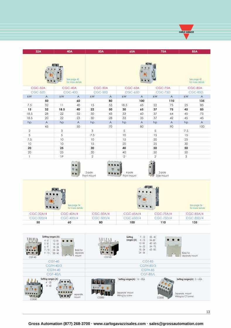
Base for separate mount
Setting ranges(A) : 16 ~ 80A
Separate mountWiring by screw
CGE80
Setting ranges(A) : 5 ~ 60A
Separate mountWiring by CT tunnelCGE60
13
Setting ranges (A)4 - 20
8 - 40
See page 42for more details
See page 42for more details
CGC-32A CGC-40A CGC-50A CGC-65A CGC-75A CGC-85A CGC-32D CGC-40D CGC-50D CGC-65D CGC-75D CGC-85D
kW A kW A kW A kW A kW A kW A50 60 80 100 110 135
7.5 32 11 40 15 55 18.5 65 22 75 25 8515 32 18.5 40 22 50 30 65 37 75 45 85
18.5 28 22 32 30 43 33 60 37 64 45 7518.5 20 22 23 30 28 33 35 37 42 45 45hp A hp A hp A hp A hp A hp A
45 50 70 80 90 1002 3 3 5 5 7.55 5 7.5 10 15 15
7.5 10 10 15 20 2510 10 15 20 25 3020 25 30 40 50 5020 25 30 40 50 501 1P 2 2 2 3
CGC-32A/4 CGC-40A/4 CGC-50A/4 CGC-65A/4 CGC-75A/4 CGC-85A/4 CGC-32D/4 CGC-40D/4 CGC-50D/4 CGC-65D/4 CGC-75D/4 CGC-85D/4
50 60 80 100 110 135
32A
See page 56for more details
See page 54for more details
Base for separate mount
CGT-85
Setting ranges (A)
CGT-40CGTH-40/3CGTH-40CGT-40/L
CGT-85CGTH-85/3CGTH-85CGT-85/L
7 - 109 - 13
12 -1816 - 2218 - 2624 - 36
28 - 4034 -5045 - 6554 - 7563 - 85
CGT-40
Setting ranges (A)
4 - 65 - 86 - 97 - 109 - 13
12 -1816 - 2218 - 2624 - 3628 - 40
separate mount
40A 50A 65A 75A 85A
CGE40
2-poleSide mount
4-poleFront mount
2-poleFront mount
Gross Automation (877) 268-3700 · www.carlogavazzisales.com · [email protected]
44
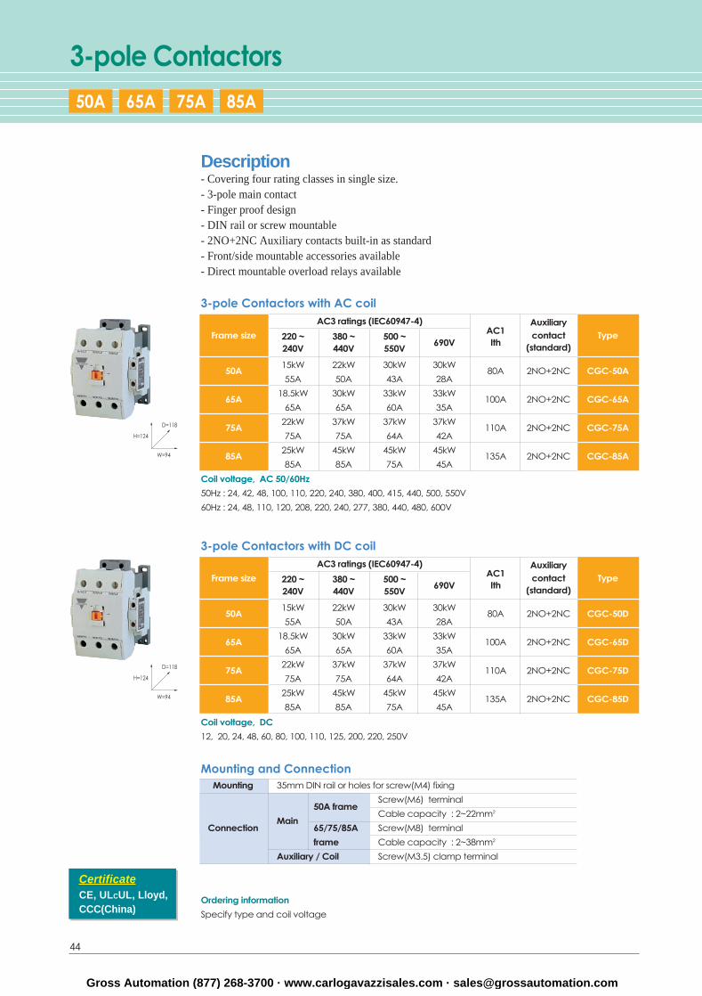
3-pole Contactors
Mounting and ConnectionMounting 35mm DIN rail or holes for screw(M4) fixing
50A frameScrew(M6) terminal
Cable capacity : 2~22mm2
ConnectionMain
65/75/85A Screw(M8) terminal
frame Cable capacity : 2~38mm2
Auxiliary / Coil Screw(M3.5) clamp terminal
3-pole Contactors with DC coilAC3 ratings (IEC60947-4)
AC1Auxiliary
Frame size 220 ~ 380 ~ 500 ~690V
contact Type240V 440V 550V
Ith (standard)
50A15kW 22kW 30kW 30kW
80A 2NO+2NC CGC-50D55A 50A 43A 28A
65A18.5kW 30kW 33kW 33kW
100A 2NO+2NC CGC-65D65A 65A 60A 35A
75A22kW 37kW 37kW 37kW
110A 2NO+2NC CGC-75D75A 75A 64A 42A
85A25kW 45kW 45kW 45kW
135A 2NO+2NC CGC-85D85A 85A 75A 45A
Coil voltage, DC
12, 20, 24, 48, 60, 80, 100, 110, 125, 200, 220, 250V
3-pole Contactors with AC coilAC3 ratings (IEC60947-4)
AC1Auxiliary
Frame size 220 ~ 380 ~ 500 ~690V
contact Type240V 440V 550V
Ith (standard)
50A15kW 22kW 30kW 30kW
80A 2NO+2NC CGC-50A55A 50A 43A 28A
65A18.5kW 30kW 33kW 33kW
100A 2NO+2NC CGC-65A65A 65A 60A 35A
75A22kW 37kW 37kW 37kW
110A 2NO+2NC CGC-75A75A 75A 64A 42A
85A25kW 45kW 45kW 45kW
135A 2NO+2NC CGC-85A85A 85A 75A 45A
Coil voltage, AC 50/60Hz
50Hz : 24, 42, 48, 100, 110, 220, 240, 380, 400, 415, 440, 500, 550V
60Hz : 24, 48, 110, 120, 208, 220, 240, 277, 380, 440, 480, 600V
Ordering information
Specify type and coil voltage
Description- Covering four rating classes in single size.- 3-pole main contact- Finger proof design- DIN rail or screw mountable- 2NO+2NC Auxiliary contacts built-in as standard- Front/side mountable accessories available- Direct mountable overload relays available
CertificateCE, ULCUL, Lloyd,CCC(China)
D=118
H=124
W=94
D=118
H=124
W=94
50A 65A 75A 85A
Gross Automation (877) 268-3700 · www.carlogavazzisales.com · [email protected]
45
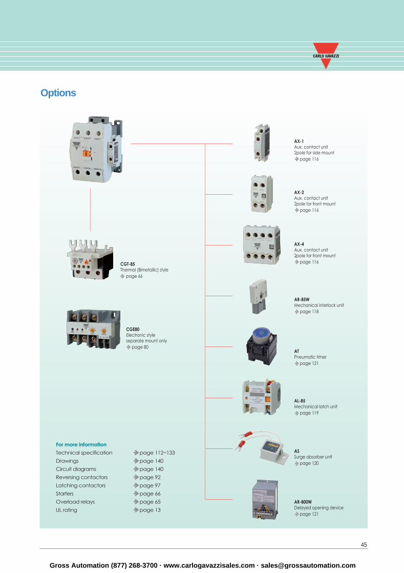
Options
For more information
Technical specification page 112~133
Drawings page 140
Circuit diagrams page 140
Reversing contactors page 92
Latching contactors page 97
Starters page 66
Overload relays page 65
UL rating page 13
CGT-85Thermal (Bimetallic) style
page 66
CGE80Electronic styleseparate mount only
page 80
AX-1Aux. contact unit2pole for side mount
page 116
AX-2Aux. contact unit2pole for front mount
page 116
AX-4Aux. contact unit2pole for front mount
page 116
AR-85WMechanical interlock unit
page 118
ATPneumatic timer
page 121
AL-85Mechanical latch unit
page 119
ASSurge absorber unit
page 120
AR-800WDelayed opening device
page 121
Gross Automation (877) 268-3700 · www.carlogavazzisales.com · [email protected]
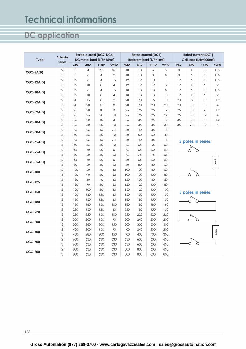
Technical informationsDC application
122
2 poles in series
3 poles in series
Type
CGC-9A(D)
CGC-12A(D)
CGC-18A(D)
CGC-22A(D)
CGC-32A(D)
CGC-40A(D)
CGC-50A(D)
CGC-65A(D)
CGC-75A(D)
CGC-85A(D)
CGC-100
CGC-125
CGC-150
CGC-180
CGC-220
CGC-300
CGC-400
CGC-600
CGC-800
2
3
2
3
2
3
2
3
2
3
2
3
2
3
2
3
2
3
2
3
2
3
2
3
2
3
2
3
2
3
2
3
2
3
2
3
2
3
24V 48V 110V 220V
8 4 2.5 0.8
8 6 4 2
12 6 4 1.2
12 10 8 4
12 6 4 1.2
12 10 8 4
20 15 8 2
20 20 15 8
25 20 10 3
25 25 20 10
35 20 10 3
35 30 20 10
45 25 15 3.5
50 35 30 12
45 25 15 3.5
50 35 30 12
65 40 20 5
80 60 50 20
65 40 20 5
80 60 50 20
100 60 40 30
100 90 80 50
120 60 40 30
120 90 80 50
150 100 80 60
150 130 120 80
180 150 120 80
180 180 150 100
220 150 120 80
220 220 150 100
300 200 150 90
300 280 200 150
400 200 150 90
400 280 200 150
630 630 630 630
630 630 630 630
800 630 630 630
800 630 630 630
24V 48V 110V 220V
10 10 6 3
10 10 8 8
12 12 10 7
12 12 12 12
18 18 13 8
18 18 18 18
20 20 15 10
20 20 20 20
25 25 25 12
25 25 25 22
35 35 25 12
35 35 35 30
50 40 35 15
50 50 50 40
50 40 35 15
65 65 65 50
75 65 50 20
75 75 75 55
80 65 50 20
80 80 80 60
100 100 80 50
100 100 100 80
120 100 80 50
120 120 100 80
150 120 100 100
150 150 150 150
180 180 150 150
180 180 180 180
220 180 150 150
220 220 220 220
300 240 200 200
300 300 300 300
400 240 200 200
400 400 400 300
630 630 630 630
630 630 630 630
800 800 630 630
800 800 800 800
24V 48V 110V 220V
8 4 2 0.3
8 6 3 0.8
12 6 3 0.5
12 10 5 2
12 6 3 0.5
12 10 5 2
20 12 3 1.2
20 15 10 4
25 15 4 1.2
25 25 12 4
35 15 4 1.2
35 25 12 4
Poles in
series
Rated current (DC2, DC4)
DC motor load (L/R=15ms)
Rated current (DC1)
Resistant load (L/R=1ms)
Rated current (DC1)
Coil load (L/R=100ms)
Gross Automation (877) 268-3700 · www.carlogavazzisales.com · [email protected]
123
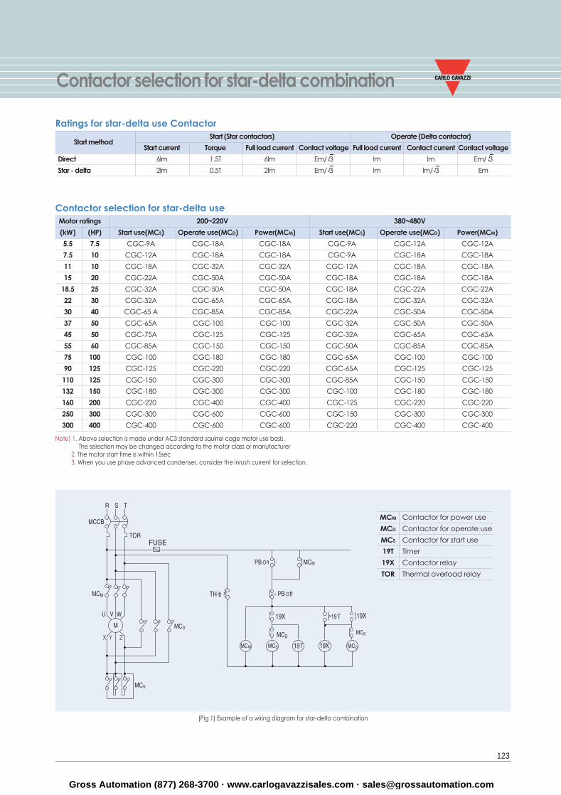
Contactor selection for star-delta combination
Start methodStart (Star contactors) Operate (Delta contactor)
Start current Torque Full load current Contact voltage Full load current Contact current Contact voltage
Direct 6lm 1.5T 6lm Em/ 3 lm lm Em/ 3
Star - delta 2lm 0.5T 2lm Em/ 3 lm lm/ 3 Em
MCM Contactor for power use
MCD Contactor for operate use
MCS Contactor for start use
19T Timer
19X Contactor relay
TOR Thermal overload relay
Ratings for star-delta use Contactor
Note) 1. Above selection is made under AC3 standard squirrel cage motor use basis.The selection may be changed according to the motor class or manufacturer
2. The motor start time is within 15sec3. When you use phase advanced condenser, consider the inrush current for selection.
(Pig 1) Example of a wiring diagram for star-delta combination
Motor ratings 200~220V 380~480V
(kW) (HP) Start use(MCS) Operate use(MCD) Power(MCM) Start use(MCS) Operate use(MCD) Power(MCM)
5.5 7.5 CGC-9A CGC-18A CGC-18A CGC-9A CGC-12A CGC-12A
7.5 10 CGC-12A CGC-18A CGC-18A CGC-9A CGC-18A CGC-18A
11 10 CGC-18A CGC-32A CGC-32A CGC-12A CGC-18A CGC-18A
15 20 CGC-22A CGC-50A CGC-50A CGC-18A CGC-18A CGC-18A
18.5 25 CGC-32A CGC-50A CGC-50A CGC-18A CGC-22A CGC-22A
22 30 CGC-32A CGC-65A CGC-65A CGC-18A CGC-32A CGC-32A
30 40 CGC-65 A CGC-85A CGC-85A CGC-22A CGC-50A CGC-50A
37 50 CGC-65A CGC-100 CGC-100 CGC-32A CGC-50A CGC-50A
45 50 CGC-75A CGC-125 CGC-125 CGC-32A CGC-65A CGC-65A
55 60 CGC-85A CGC-150 CGC-150 CGC-50A CGC-85A CGC-85A
75 100 CGC-100 CGC-180 CGC-180 CGC-65A CGC-100 CGC-100
90 125 CGC-125 CGC-220 CGC-220 CGC-65A CGC-125 CGC-125
110 125 CGC-150 CGC-300 CGC-300 CGC-85A CGC-150 CGC-150
132 150 CGC-180 CGC-300 CGC-300 CGC-100 CGC-180 CGC-180
160 200 CGC-220 CGC-400 CGC-400 CGC-125 CGC-220 CGC-220
250 300 CGC-300 CGC-600 CGC-600 CGC-150 CGC-300 CGC-300
300 400 CGC-400 CGC-600 CGC-600 CGC-220 CGC-400 CGC-400
Contactor selection for star-delta use
Gross Automation (877) 268-3700 · www.carlogavazzisales.com · [email protected]
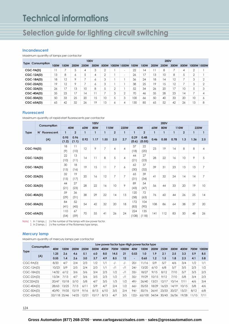
Technical informationsSelection guide for lighting circuit switching
124
IncandescentMaximum quantity of lamps per contactor
Type Consumption100V 200V
100W 150W 200W 250W 300W 500W 1000W 1500W 100W 150W 200W 250W 300W 500W 1000W 1500W
CGC-9A(D) 11 7 5 4 3 2 1 - 22 14 11 8 7 4 2 1
CGC-12A(D) 13 8 6 5 4 2 1 - 26 17 13 10 8 5 2 1
CGC-18A(D) 18 12 9 7 6 3 1 1 36 24 18 14 12 7 3 2
CGC-22A(D) 19 12 9 7 6 3 1 1 38 25 19 15 12 7 3 2
CGC-32A(D) 26 17 13 10 8 5 2 1 52 34 26 20 17 10 5 3
CGC-40A(D) 35 23 17 14 11 7 3 2 70 46 35 28 23 14 7 4
CGC-50A(D) 50 33 25 20 15 10 5 3 100 66 50 40 33 20 10 6
CGC-65A(D) 65 42 32 26 19 13 6 4 130 85 65 52 42 26 13 8
Note) 1. In 1 lamps, ( ) is the number of the lamps with low power factor.2. In 2 lamps, ( ) is the number of the flickemess type lamps.
Mercury lampMaximum quantity of mercury lamps per contactor
ConsumptionLow power factor type-High power factor type
Type 40W 100W 200W 250W 300W 400W 700W 1000W 40W 100W 200W 250W 300W 400W 700W 1000W
(A)1.25 2.6 4.6 5.1 6.0 8.0 14.5 21 0.53 1.0 1.9 2.1 2.5 3.3 5.9 8.5
0.55 1.4 2.6 3.0 3.7 4.9 8.5 12 - 0.65 1.2 1.5 1.8 2.3 4.1 5.8
CGC-9A(D) 8/20 4/7 2/4 2/3 1/2 1/1 -/- -/- 20/- 11/16 5/9 5/7 4/6 3/4 1/2 1/1
CGC-12A(D) 10/23 5/9 2/5 2/4 2/3 1/1 -/1 -/1 24/- 13/20 6/10 6/8 5/7 3/5 2/3 1/2
CGC-18A(D) 14/32 6/12 3/6 3/6 3/4 2/3 1/2 -/1 33/- 18/27 9/15 8/12 7/10 5/7 3/3 2/3
CGC-22A(D) 15/34 7/13 4/7 3/6 3/5 2/3 1/2 -/1 35/- 19/29 10/15 9/12 7/10 5/8 3/4 2/3
CGC32A(D) 20/47 10/18 5/10 5/8 4/7 3/5 1/3 1/2 49/- 26/40 13/21 12/17 10/14 7/11 4/6 3/4
CGC-40A(D) 28/63 13/25 7/13 6/11 5/9 4/7 2/4 1/2 66/- 35/53 18/29 16/23 14/19 10/15 5/8 4/6
CGC-50A(D) 40/90 19/35 10/19 9/16 8/13 6/10 3/5 2/4 94/- 50/76 26/41 23/33 20/27 15/21 8/12 6/8
CGC-65A(D) 52/118 25/46 14/25 12/21 10/17 8/13 4/7 3/5 122/- 65/100 34/54 30/43 26/36 19/28 11/15 7/11
FluorescentMaximum quantity of rapid-start fluorescents per contactor
Consumption100V 200V
40W 60W 80W 110W 220W 40W 60W 80W 110W 220W
Type N Fluorescent. 1 2 1 1 1 2 1 1 2 1 1 1 2 1 1
(A)0.95 0.96
0.92 1.17 1.55 2.5 2.70.29 0.48
0.46 0.58 0.78 1.3 1.36 2.5(1.2) (1.1) (0.6) (0.55)
CGC-9A(D)18 11
12 9 7 4 437 22
23 19 14 8 8 4(9) (10) (18) (20)
CGC-12A(D)22 13
14 11 8 5 444 27
28 22 16 10 9 5(10) (11) (21) (23)
CGC-18A(D)30 18
19 15 11 7 662 37
39 31 23 13 13 7(15) (16) (30) (32)
CGC-22A(D)32 19
20 16 12 7 765 39
41 32 24 14 14 7(15) (17) (31) (34)
CGC-32A(D)44 27
28 22 16 10 989 54
56 44 33 20 19 10(21) (23) (43) (47)
CGC-40A(D)59 36
38 29 22 14 13120 72
76 60 44 26 25 14(29) (31) (58) (63)
CGC-50A(D)84 52
54 42 32 20 18172 104
108 86 64 38 37 20(41) (45) (83) (90)
CGC-65A(D)110 67
70 55 41 26 24224 135
141 112 83 50 48 26(54) (59) (108) (118)
Gross Automation (877) 268-3700 · www.carlogavazzisales.com · [email protected]
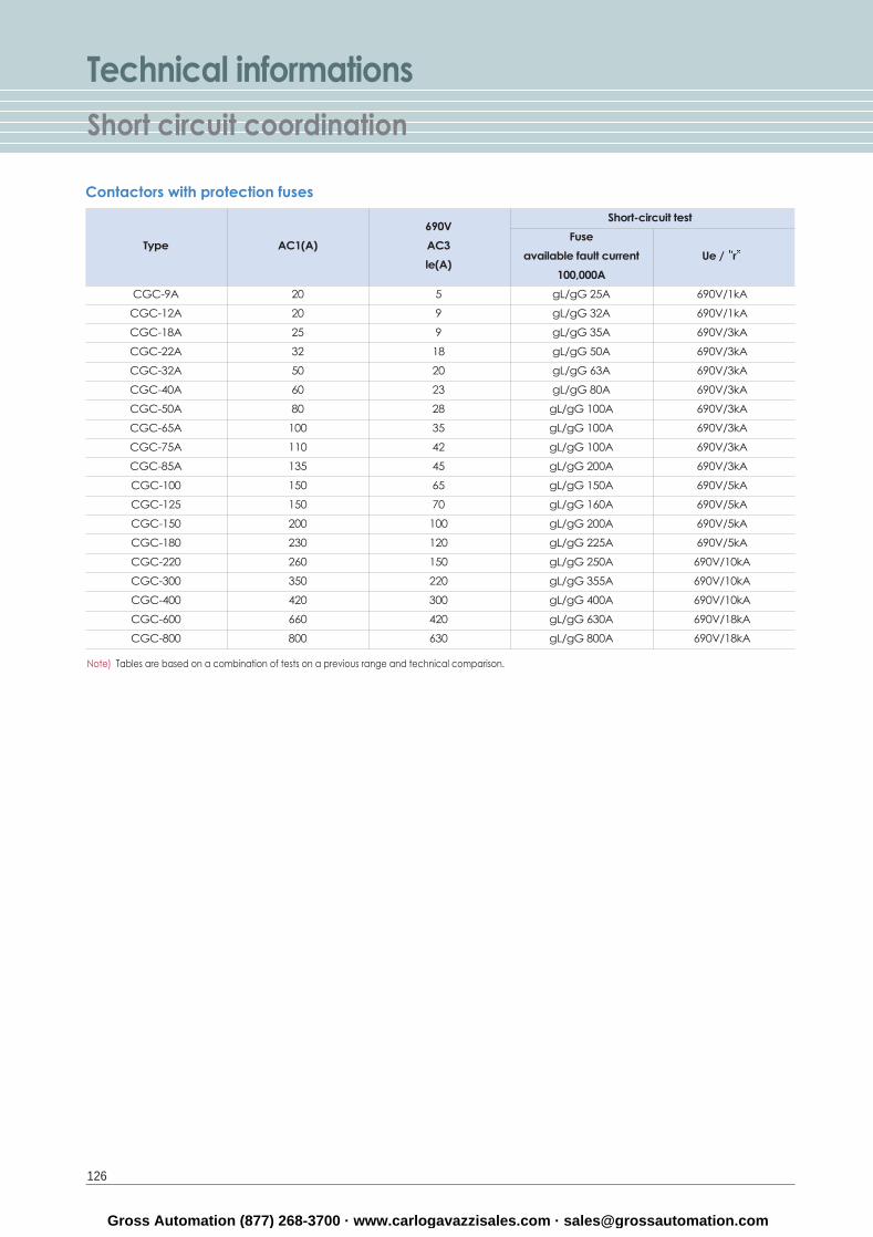
Technical informationsShort circuit coordination
126
Note) Tables are based on a combination of tests on a previous range and technical comparison.
690VShort-circuit test
Type AC1(A) AC3 Fuse
le(A)available fault current Ue / r
100,000A
CGC-9A 20 5 gL/gG 25A 690V/1kA
CGC-12A 20 9 gL/gG 32A 690V/1kA
CGC-18A 25 9 gL/gG 35A 690V/3kA
CGC-22A 32 18 gL/gG 50A 690V/3kA
CGC-32A 50 20 gL/gG 63A 690V/3kA
CGC-40A 60 23 gL/gG 80A 690V/3kA
CGC-50A 80 28 gL/gG 100A 690V/3kA
CGC-65A 100 35 gL/gG 100A 690V/3kA
CGC-75A 110 42 gL/gG 100A 690V/3kA
CGC-85A 135 45 gL/gG 200A 690V/3kA
CGC-100 150 65 gL/gG 150A 690V/5kA
CGC-125 150 70 gL/gG 160A 690V/5kA
CGC-150 200 100 gL/gG 200A 690V/5kA
CGC-180 230 120 gL/gG 225A 690V/5kA
CGC-220 260 150 gL/gG 250A 690V/10kA
CGC-300 350 220 gL/gG 355A 690V/10kA
CGC-400 420 300 gL/gG 400A 690V/10kA
CGC-600 660 420 gL/gG 630A 690V/18kA
CGC-800 800 630 gL/gG 800A 690V/18kA
Contactors with protection fuses
Gross Automation (877) 268-3700 · www.carlogavazzisales.com · [email protected]
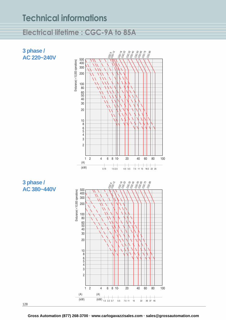
Technical informationsElectrical lifetime : CGC-9A to 85A
128
3 phase / AC 220~240V
3 phase / AC 380~440V
Gross Automation (877) 268-3700 · www.carlogavazzisales.com · [email protected]
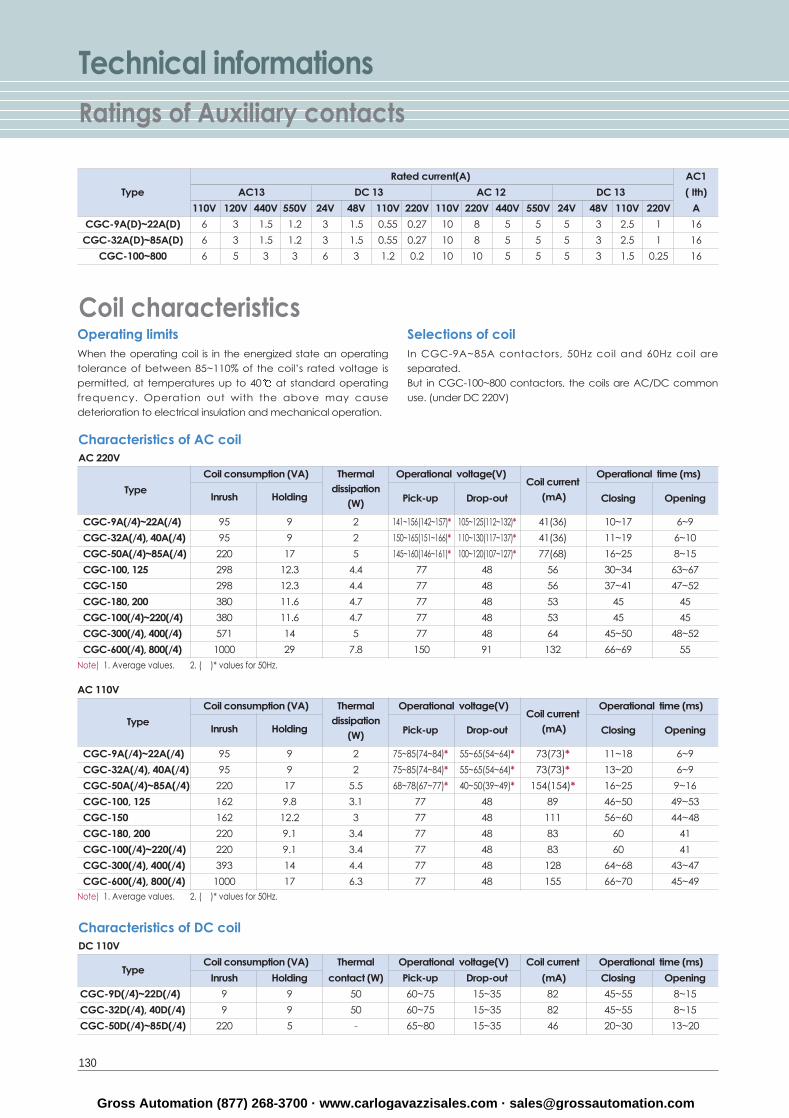
Rated current(A) AC1
Type AC13 DC 13 AC 12 DC 13 ( Ith)
110V 120V 440V 550V 24V 48V 110V 220V 110V 220V 440V 550V 24V 48V 110V 220V A
CGC-9A(D)~22A(D) 6 3 1.5 1.2 3 1.5 0.55 0.27 10 8 5 5 5 3 2.5 1 16
CGC-32A(D)~85A(D) 6 3 1.5 1.2 3 1.5 0.55 0.27 10 8 5 5 5 3 2.5 1 16
CGC-100~800 6 5 3 3 6 3 1.2 0.2 10 10 5 5 5 3 1.5 0.25 16
Technical informationsRatings of Auxiliary contacts
130
Coil characteristicsOperating limitsWhen the operating coil is in the energized state an operatingtolerance of between 85~110% of the coil’s rated voltage ispermitted, at temperatures up to 40 at standard operatingfrequency. Operation out with the above may causedeterioration to electrical insulation and mechanical operation.
Selections of coilIn CGC-9A~85A contactors, 50Hz coil and 60Hz coil areseparated.But in CGC-100~800 contactors, the coils are AC/DC commonuse. (under DC 220V)
Characteristics of AC coilAC 220V
AC 110V
Note) 1. Average values. 2. ( )* values for 50Hz.
Coil consumption (VA) Thermal Operational voltage(V)Coil current
Operational time (ms)
TypeInrush Holding
dissipationPick-up Drop-out (mA) Closing Opening(W)
CGC-9A(/4)~22A(/4) 95 9 2 141~156(142~157)* 105~125(112~132)* 41(36) 10~17 6~9
CGC-32A(/4), 40A(/4) 95 9 2 150~165(151~166)* 110~130(117~137)* 41(36) 11~19 6~10
CGC-50A(/4)~85A(/4) 220 17 5 145~160(146~161)* 100~120(107~127)* 77(68) 16~25 8~15
CGC-100, 125 298 12.3 4.4 77 48 56 30~34 63~67
CGC-150 298 12.3 4.4 77 48 56 37~41 47~52
CGC-180, 200 380 11.6 4.7 77 48 53 45 45
CGC-100(/4)~220(/4) 380 11.6 4.7 77 48 53 45 45
CGC-300(/4), 400(/4) 571 14 5 77 48 64 45~50 48~52
CGC-600(/4), 800(/4) 1000 29 7.8 150 91 132 66~69 55
Characteristics of DC coilDC 110V
Coil consumption (VA) Thermal Operational voltage(V) Coil current Operational time (ms)Type
Inrush Holding contact (W) Pick-up Drop-out (mA) Closing Opening
CGC-9D(/4)~22D(/4) 9 9 50 60~75 15~35 82 45~55 8~15
CGC-32D(/4), 40D(/4) 9 9 50 60~75 15~35 82 45~55 8~15
CGC-50D(/4)~85D(/4) 220 5 - 65~80 15~35 46 20~30 13~20
Note) 1. Average values. 2. ( )* values for 50Hz.
Coil consumption (VA) Thermal Operational voltage(V)Coil current
Operational time (ms)
TypeInrush Holding
dissipationPick-up Drop-out (mA) Closing Opening(W)
CGC-9A(/4)~22A(/4) 95 9 2 75~85(74~84)* 55~65(54~64)* 73(73)* 11~18 6~9
CGC-32A(/4), 40A(/4) 95 9 2 75~85(74~84)* 55~65(54~64)* 73(73)* 13~20 6~9
CGC-50A(/4)~85A(/4) 220 17 5.5 68~78(67~77)* 40~50(39~49)* 154(154)* 16~25 9~16
CGC-100, 125 162 9.8 3.1 77 48 89 46~50 49~53
CGC-150 162 12.2 3 77 48 111 56~60 44~48
CGC-180, 200 220 9.1 3.4 77 48 83 60 41
CGC-100(/4)~220(/4) 220 9.1 3.4 77 48 83 60 41
CGC-300(/4), 400(/4) 393 14 4.4 77 48 128 64~68 43~47
CGC-600(/4), 800(/4) 1000 17 6.3 77 48 155 66~70 45~49
Gross Automation (877) 268-3700 · www.carlogavazzisales.com · [email protected]
131
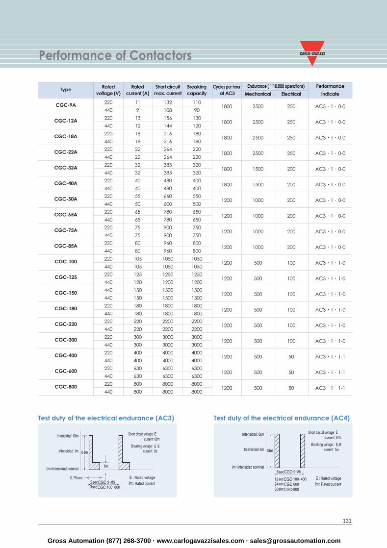
Performance of Contactors
Test duty of the electrical endurance (AC3) Test duty of the electrical endurance (AC4)
Rated Rated Short circuit Breaking Cycles per hour Endurance ( 10,000 operations) Performancevoltage (V) current (A) max. current capacity at AC3 Mechanical Electrical Indicate
220 11 132 1101800 2500 250 AC3 1 0-0
440 9 108 90
220 13 156 1301800 2500 250 AC3 1 0-0
440 12 144 120
220 18 216 1801800 2500 250 AC3 1 0-0
440 18 216 180
220 22 264 2201800 2500 250 AC3 1 0-0
440 22 264 220
220 32 385 3201800 1500 200 AC3 1 0-0
440 32 385 320
220 40 480 4001800 1500 200 AC3 1 0-0
440 40 480 400
220 55 660 5501200 1000 200 AC3 1 0-0
440 50 600 500
220 65 780 6501200 1000 200 AC3 1 0-0
440 65 780 650
220 75 900 7501200 1000 200 AC3 1 0-0
440 75 900 750
220 80 960 8001200 1000 200 AC3 1 0-0
440 80 960 800
220 105 1050 10501200 500 100 AC3 1 1-0
440 105 1050 1050
220 125 1250 12501200 500 100 AC3 1 1-0
440 120 1200 1200
440 150 1500 15001200 500 100 AC3 1 1-0
440 150 1500 1500
220 180 1800 18001200 500 100 AC3 1 1-0
440 180 1800 1800
220 220 2200 22001200 500 100 AC3 1 1-0
440 220 2200 2200
220 300 3000 30001200 500 100 AC3 1 1-0
440 300 3000 3000
220 400 4000 40001200 500 50 AC3 1 1-1
440 400 4000 4000
220 630 6300 63001200 500 50 AC3 1 1-1
440 630 6300 6300
220 800 8000 80001200 500 50 AC3 1 1-1
440 800 8000 8000
Type
CGC-9A
CGC-12A
CGC-18A
CGC-22A
CGC-32A
CGC-40A
CGC-50A
CGC-65A
CGC-75A
CGC-85A
CGC-100
CGC-125
CGC-150
CGC-180
CGC-220
CGC-300
CGC-400
CGC-600
CGC-800
Gross Automation (877) 268-3700 · www.carlogavazzisales.com · [email protected]
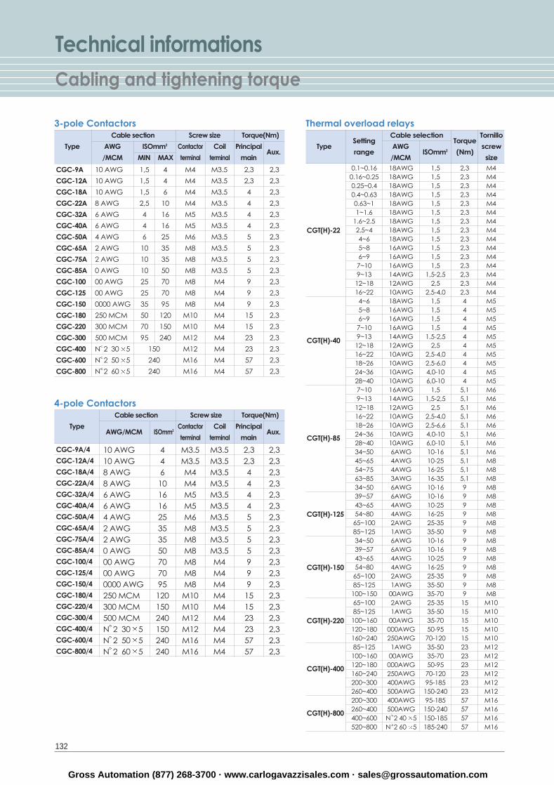
Technical informationsCabling and tightening torque
132
3-pole Contactors
10 AWG 1,5 4 M4 M3.5 2,3 2,3
10 AWG 1,5 4 M4 M3.5 2,3 2,3
10 AWG 1,5 6 M4 M3.5 4 2,3
8 AWG 2,5 10 M4 M3.5 4 2,3
6 AWG 4 16 M5 M3.5 4 2,3
6 AWG 4 16 M5 M3.5 4 2,3
4 AWG 6 25 M6 M3.5 5 2,3
2 AWG 10 35 M8 M3.5 5 2,3
2 AWG 10 35 M8 M3.5 5 2,3
0 AWG 10 50 M8 M3.5 5 2,3
00 AWG 25 70 M8 M4 9 2,3
00 AWG 25 70 M8 M4 9 2,3
0000 AWG 35 95 M8 M4 9 2,3
250 MCM 50 120 M10 M4 15 2,3
300 MCM 70 150 M10 M4 15 2,3
500 MCM 95 240 M12 M4 23 2,3
N 2 30 5 150 M12 M4 23 2,3
N 2 50 5 240 M16 M4 57 2,3
N 2 60 5 240 M16 M4 57 2,3
Cable section Screw size Torque(Nm)
Type AWG ISOmm2 Contactor Coil Principal
/MCM MIN MAX terminal terminal mainAux.
SettingCable selection
TorqueTornillo
Typerange
AWGISOmm2 (Nm)
screw
/MCM size
Thermal overload relays
0.1~0.16 18AWG 1,5 2,3 M40.16~0.25 18AWG 1,5 2,3 M40.25~0.4 18AWG 1,5 2,3 M40.4~0.63 18AWG 1,5 2,3 M40.63~1 18AWG 1,5 2,3 M41~1.6 18AWG 1,5 2,3 M4
1.6~2.5 18AWG 1,5 2,3 M42.5~4 18AWG 1,5 2,3 M44~6 18AWG 1,5 2,3 M45~8 16AWG 1,5 2,3 M46~9 16AWG 1,5 2,3 M47~10 16AWG 1,5 2,3 M49~13 14AWG 1,5-2,5 2,3 M412~18 12AWG 2,5 2,3 M416~22 10AWG 2,5-4,0 2,3 M44~6 18AWG 1,5 4 M55~8 16AWG 1,5 4 M56~9 16AWG 1,5 4 M57~10 16AWG 1,5 4 M59~13 14AWG 1,5-2,5 4 M512~18 12AWG 2,5 4 M516~22 10AWG 2,5-4,0 4 M518~26 10AWG 2,5-6,0 4 M524~36 10AWG 4,0-10 4 M528~40 10AWG 6,0-10 4 M57~10 16AWG 1,5 5,1 M69~13 14AWG 1,5-2,5 5,1 M612~18 12AWG 2,5 5,1 M616~22 10AWG 2,5-4,0 5,1 M618~26 10AWG 2,5-6,6 5,1 M624~36 10AWG 4,0-10 5,1 M628~40 10AWG 6,0-10 5,1 M634~50 6AWG 10-16 5,1 M645~65 4AWG 10-25 5,1 M854~75 4AWG 16-25 5,1 M863~85 3AWG 16-35 5,1 M834~50 6AWG 10-16 9 M839~57 6AWG 10-16 9 M843~65 4AWG 10-25 9 M854~80 4AWG 16-25 9 M865~100 2AWG 25-35 9 M885~125 1AWG 35-50 9 M834~50 6AWG 10-16 9 M839~57 6AWG 10-16 9 M843~65 4AWG 10-25 9 M854~80 4AWG 16-25 9 M865~100 2AWG 25-35 9 M885~125 1AWG 35-50 9 M8100~150 00AWG 35-70 9 M865~100 2AWG 25-35 15 M1085~125 1AWG 35-50 15 M10100~160 00AWG 35-70 15 M10120~180 000AWG 50-95 15 M10160~240 250AWG 70-120 15 M1085~125 1AWG 35-50 23 M12100~160 00AWG 35-70 23 M12120~180 000AWG 50-95 23 M12160~240 250AWG 70-120 23 M12200~300 400AWG 95-185 23 M12260~400 500AWG 150-240 23 M12200~300 400AWG 95-185 57 M16260~400 500AWG 150-240 57 M16400~600 N 2 40 5 150-185 57 M16520~800 N 2 60 5 185-240 57 M16
CGT(H)-22
CGT(H)-40
CGT(H)-85
CGT(H)-125
CGT(H)-150
CGT(H)-220
CGT(H)-400
CGT(H)-800
CGC-9A
CGC-12A
CGC-18A
CGC-22A
CGC-32A
CGC-40A
CGC-50A
CGC-65A
CGC-75A
CGC-85A
CGC-100
CGC-125
CGC-150
CGC-180
CGC-220
CGC-300
CGC-400
CGC-600
CGC-800
4-pole Contactors
10 AWG 4 M3.5 M3.5 2,3 2,310 AWG 4 M3.5 M3.5 2,3 2,38 AWG 6 M4 M3.5 4 2,38 AWG 10 M4 M3.5 4 2,36 AWG 16 M5 M3.5 4 2,36 AWG 16 M5 M3.5 4 2,34 AWG 25 M6 M3.5 5 2,32 AWG 35 M8 M3.5 5 2,32 AWG 35 M8 M3.5 5 2,30 AWG 50 M8 M3.5 5 2,300 AWG 70 M8 M4 9 2,300 AWG 70 M8 M4 9 2,30000 AWG 95 M8 M4 9 2,3250 MCM 120 M10 M4 15 2,3300 MCM 150 M10 M4 15 2,3500 MCM 240 M12 M4 23 2,3N 2 30 5 150 M12 M4 23 2,3N 2 50 5 240 M16 M4 57 2,3N 2 60 5 240 M16 M4 57 2,3
Cable section Screw size Torque(Nm)
TypeAWG/MCM ISOmm2
Contactor Coil Principal
terminal terminal mainAux.
CGC-9A/4
CGC-12A/4
CGC-18A/4
CGC-22A/4
CGC-32A/4
CGC-40A/4
CGC-50A/4
CGC-65A/4
CGC-75A/4
CGC-85A/4
CGC-100/4
CGC-125/4
CGC-150/4
CGC-180/4
CGC-220/4
CGC-300/4
CGC-400/4
CGC-600/4
CGC-800/4
Gross Automation (877) 268-3700 · www.carlogavazzisales.com · [email protected]
133
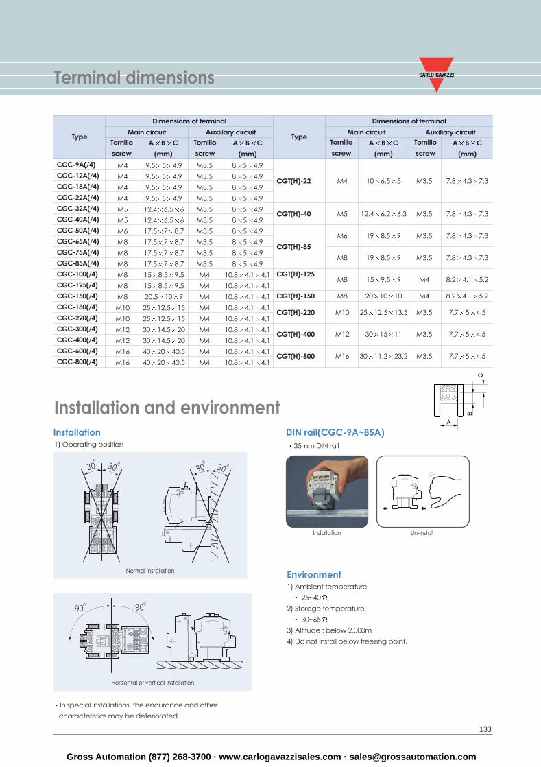
Terminal dimensions
Installation and environment
Environment1) Ambient temperature
-25~40
2) Storage temperature
-30~65
3) Altitude : below 2,000m
4) Do not install below freezing point.
DIN rail(CGC-9A~85A)35mm DIN rail
Installation Un-install
Main circuit Auxiliary circuitTornillo
screw
A B C
(mm)
Tornillo
screw
A B C
(mm)
Type
CGC-9A(/4)
CGC-12A(/4)
CGC-18A(/4)
CGC-22A(/4)
CGC-32A(/4)
CGC-40A(/4)
CGC-50A(/4)
CGC-65A(/4)
CGC-75A(/4)
CGC-85A(/4)
CGC-100(/4)
CGC-125(/4)
CGC-150(/4)
CGC-180(/4)
CGC-220(/4)
CGC-300(/4)
CGC-400(/4)
CGC-600(/4)
CGC-800(/4)
M4 9.5 5 4.9 M3.5 8 5 4.9
M4 9.5 5 4.9 M3.5 8 5 4.9
M4 9.5 5 4.9 M3.5 8 5 4.9
M4 9.5 5 4.9 M3.5 8 5 4.9
M5 12.4 6.5 6 M3.5 8 5 4.9
M5 12.4 6.5 6 M3.5 8 5 4.9
M6 17.5 7 8.7 M3.5 8 5 4.9
M8 17.5 7 8.7 M3.5 8 5 4.9
M8 17.5 7 8.7 M3.5 8 5 4.9
M8 17.5 7 8.7 M3.5 8 5 4.9
M8 15 8.5 9.5 M4 10.8 4.1 4.1
M8 15 8.5 9.5 M4 10.8 4.1 4.1
M8 20.5 10 9 M4 10.8 4.1 4.1
M10 25 12.5 15 M4 10.8 4.1 4.1
M10 25 12.5 15 M4 10.8 4.1 4.1
M12 30 14.5 20 M4 10.8 4.1 4.1
M12 30 14.5 20 M4 10.8 4.1 4.1
M16 40 20 40.5 M4 10.8 4.1 4.1
M16 40 20 40.5 M4 10.8 4.1 4.1
Dimensions of terminal
Main circuit Auxiliary circuitTornillo
screw
Tornillo
screwA B C
(mm)
Type
CGT(H)-22
CGT(H)-40
CGT(H)-85
CGT(H)-125
CGT(H)-150
CGT(H)-220
CGT(H)-400
CGT(H)-800
M4 10 6.5 5 M3.5 7.8 4.3 7.3
M5 12.4 6.2 6.3 M3.5 7.8 4.3 7.3
M6 19 8.5 9 M3.5 7.8 4.3 7.3
M8 19 8.5 9 M3.5 7.8 4.3 7.3
M8 15 9.5 9 M4 8.2 4.1 5.2
M8 20 10 10 M4 8.2 4.1 5.2
M10 25 12.5 13.5 M3.5 7.7 5 4.5
M12 30 15 11 M3.5 7.7 5 4.5
M16 30 11.2 23.2 M3.5 7.7 5 4.5
Dimensions of terminal
A B C
(mm)
In special installations, the endurance and other
characteristics may be deteriorated.
Horizontal or vertical installation
Installation1) Operating position
Normal installation
Gross Automation (877) 268-3700 · www.carlogavazzisales.com · [email protected]
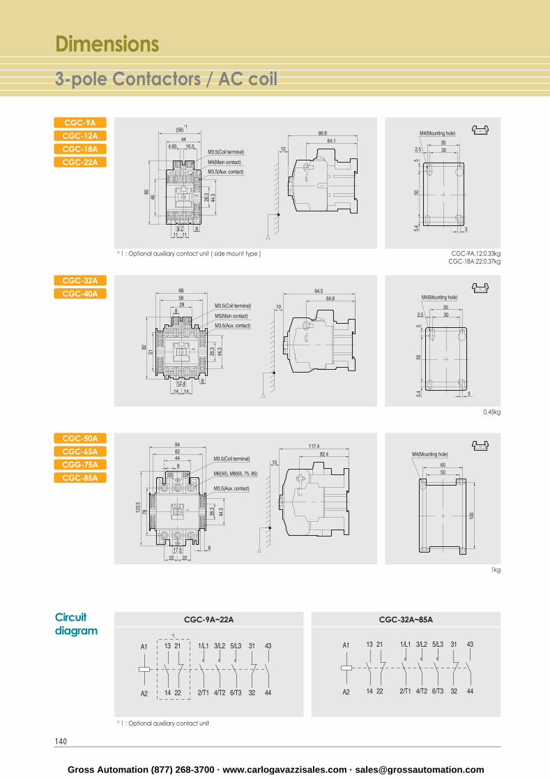
Dimensions3-pole Contactors / AC coil
CGC-9A
CGC-12A
CGC-18A
CGC-22A
1 : Optional auxiliary contact unit ( side mount type )
CGC-32A
CGC-40A
CGC-50A
CGC-65A
CGG-75A
CGC-85A
Circuitdiagram
1 : Optional auxiliary contact unit
CGC-9A,12:0.33kgCGC-18A,22:0.37kg
0.45kg
1kg
CGC-9A~22A CGC-32A~85A
140
Gross Automation (877) 268-3700 · www.carlogavazzisales.com · [email protected]
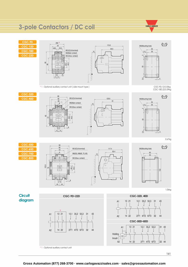
3-pole Contactors / DC coil
141
CGC-9D
CGC-12D
CGC-18D
CGC-22D
1 : Optional auxiliary contact unit ( side mount type )
CGC-32D
CGC-40D
CGC-50D
CGC-65D
CGC-75D
CGC-85D
Circuitdiagram
1 : Optional auxiliary contact unit
CGC-9D,12:0.55kgCGC-18D,22:0.59kg
0.67kg
1.06kg
CGC-9D~22D CGC-32D, 40D
CGC-50D~85D
Gross Automation (877) 268-3700 · www.carlogavazzisales.com · [email protected]