Embed Size (px)
Citation preview
*33 NATIONAL AVIATION FACILITIES EXPERIMENTAL CENTER ATL--M4 Ir? C 1FU?UNCLASIFPIO PAA-A-?10 ML
"Lc ?S INIIII I"1
l llI IIniIII II II III Ii',mii 111111mnm iF
Repsrt No. FAA-NA-19.40 % K
EXHAUST EMISSIONS CHARACTERISTICS FOR A GENERAL AVIATIONLIGHT-AIRCRAFT TELEDYNE CONTINENTAL MOTORS
(RCM) GTSIO-520-K PISTON ENGINE
Eric E. Becker
DECEMBER 1979
FINAL REPORT
Document is available to the U.S. public throughthe National Technical Information Service, 4
Springfield, Virginia 22161.
Prepard fr
U.S. DEPARTMENT OF TRANSPORTATIONC-, FEDERAL AVIATION ADMNISTRATION
Sstems Research & Deveopmt Servicewashbigtn, DrC. 2o30
80 2 8 7..........
NOT ICE
The United States Government does not endorse productsor manufacturers. Trade or manufacturer's names appearherein solely because they are considered essential tothe object of this report.
Technical Report Documentation Page
1. Report No. 2. Government Accession No. 3. Recipient's Catalog No.FAA-NA-79-40e'
--4. Title and Subtltle. 5. W a'U.WA
'L EXHAUSTJMISSIONS CHARACTERISTICS FOR A ,.ENERAL ______ V977AVIATION IGHT-. RCRAFT TELEDYNE CONTINENTAL MOTORS C
Ti ,10-5 PISTON ENGINEo _ / _od.
.. P...4.,mm~a, e...ai~a~ition Report No.7.Eric E. ecker / FAA-NA-79-40&_
9. Performing Organiza t-io--n Name anid Address - 10. Work _1371 No. (T"RAIS)
Federal Aviation AdministrationNational Aviation Facilities Experimental Center II. Contract or Grant No.Atlantic City, New Jersey 08405 201-521-100
13. Typ - . 1..d .bvvmd -.
112. Sponsoring Agency Name and Address .
U.S. Department of Transportation . FinalFederal Aviation Administration -. , 2 / 1Systems Research and Development Service/ ... - 14. Sponsri,,n Aecy e0*rWashington, D.C. 20590
15. Supplementary Notes
16. Abstract
The Teledyne Continental Motors (TCM) GTSIO-520-K engine (S/N220015) was tested at
the National Aviation Facilities Experimental Center (NAFEC) to develop an exhaustemissions data base. This data base consists of current production baselineemissions characteristics, lean-out emissions data, effects of leaning-out thefuel schedule on cylinder head temperatures, and data showing ambient effects onexhaust emissions and cylinder head temperatures. The engine operation with it.
current full-rich production fuel schedule could not meet the proposed Environ-mental Protection Agency (EPA) standard for carbon monoxide (CO) and unburnedhydrocarbons (HC) under sea level standard-day conditions. The engine did, however,meet the proposed EPA standard for oxides of nitrogen (Ndx) under the same sea
level conditions. The results of engine testing under different ambient conditiors(essentially sea level standard day to sea level hot day) are also presented andthese results show a trend toward higher levels of emissions output for CO and HCwhile producing slightly lower levels of NO.'O
17. Key Words 18. Distribution StatementGeneral Aviation Piston Engines Document is available to the U.S. publicOxides of Nitrogen Carbon Monoxide through the National Technical InformationEmissions (Pollution) Service, Springfield, Virginia 22161.Unburned Hydrocarbons
19. Securitr Cleseif, (of this report) 20. Security C|I.slf. (of this poge) 21. No. of Pages 22. Price
Unclassified Unclassified 5i
Form DOT F 1700.7 (9-72) Repreductien of completed Peger authorized
IIL
E 0
-2 00
*0 6Sc 6 3
6-
IC UsF "CC
32 1
U~ T,-
TABLE OF CONTENTS
Page
INTRODUCTION 1
Purpose 1
Background 1
DISCUSSION 2
Description of Teledyne Continental Motors (TCM) 2GTSIO-520-K Engine
Description of Test Set-Up and Basic Facilities 2Description of Air Induction System and Airflow Comrutations 5Description of Fuel Flow System 5Description of Cooling Air System 7Description of Test Procedures and EPA Standards 7Description of Emissions Measurement System (Reference 3). 10Description of Sample Handling System 15
Description of Filtration System 15Computation Procedures 16
RESULTS 23
General Comments 23Results of Baseline Tests (Landing-Takeoff Cycle Effects) 23Results of Lean-Out Tests 24
SUMMARY OF RESULTS 3
Exhaust Emissions 34Maximum Cylinder Head Temperatures 34Critical Landing and Takeoff Cycle 34
CONCLUS IONS 34
REFERENCES 36
APPENDICES
A Fuel Sample AnalysisB Composition of Air (General Properties)C NAPEC Test Data and Working Plots for Analysis and Evaluation
Teledyne Continental Motors (TCM) GTSIO-520-K Engine
C, A
00
LIST OF ILLUSTRATIONS
Figure Page
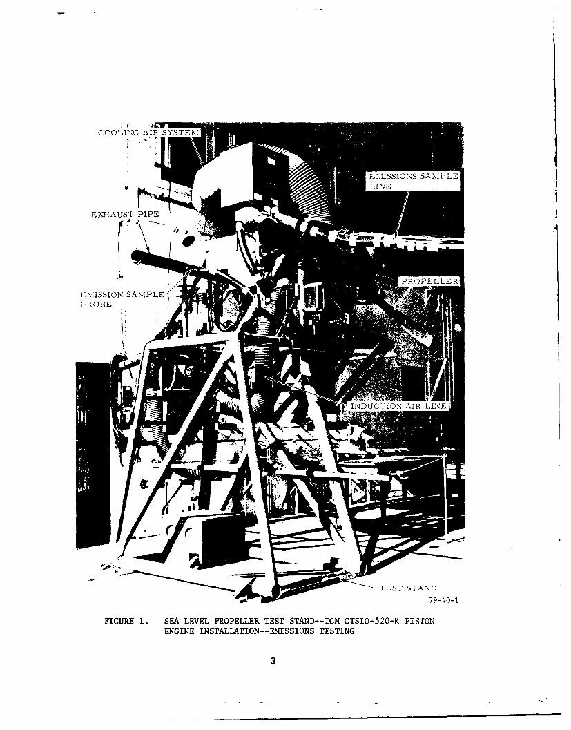
1 Sea Level Propeller Test Stand--TCM GTSIO-520-K 3Piston Engine Installation--Emissions Testing
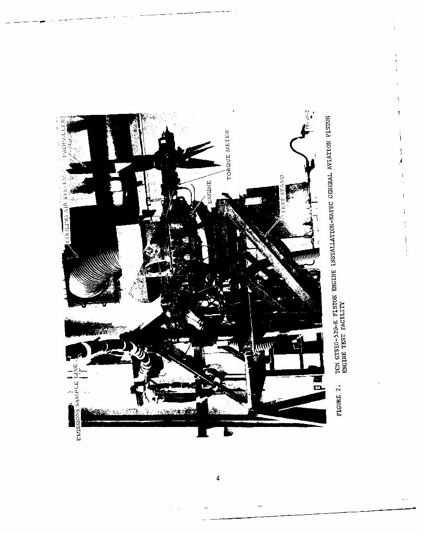
2 TCM GTSIO-520-K Engine Installation--NAFEC General 4Aviation Pistion Engine Test Facility
3 NAFEC Air Induction (Airflow Measurement) System for Light- 6Aircraft Piston Engine Emission Tests
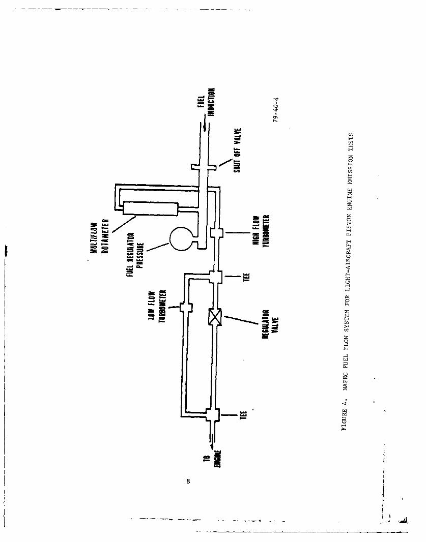
4 NAFEC Fuel Flow System for Light-Aircraft Piston Engine 8Emission Tests
5 Schematic of Emissions Measurement Systems 11and its Measurement Characteristics
6 Beckman Model 402 THC Analyzer (1.5 PSI Unmodified) 13
7 Beckman Model 402 THC Analyzer (1.5 PSI Modified) 13
8 Beckman Model 402 THC Analyzer (3 PSI Unmodified) 14
9 Exhaust Gas Molecular Weights 18
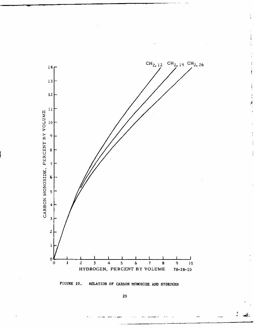
10 Relation of Carbon Monoxide and Hydrogen 20
11 Total Emissions Characteristics for a TCM GTSIO-520-K 25Engine Operating under Varying Sea Level AmbientConditions--Table 5 Minimum Five-Mode LTO Cycle--Production Rich Limit Fuel Schedule
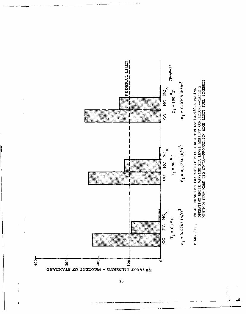
12 Total Emissions Characterics for a TCM GTSIO-520-K 26Engine with Different Fuel Schedule Adjustments--Sea Level Standard Day--Table 5 Minumum Five-Mode
LTO Cycle
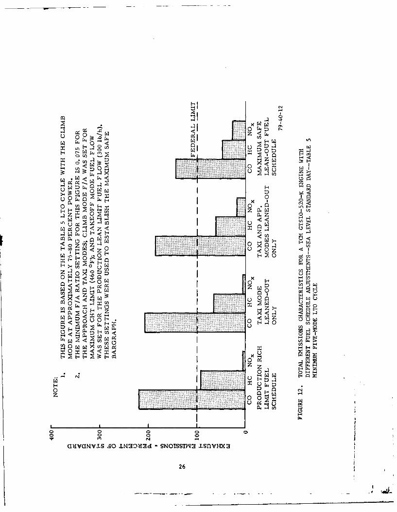
13 Total Emissions Characteristies for a TCM GTSIO-520-K 27Engine with Different Fuel Schedule Adjustments--Sea Level Standard Day--Table 4 Maximum Five-ModeLTO Cycle
14 Sea Level Standard-Day Maximum Cylinder Head Temperatures 31for Different Power Mode Conditions and Varying Fuel-AirRatios--TCM GTSIO-520-K Engine
15 Sea Level 1jot-Day (Ti-103* F) Maximum Cylinder Head 32104e tre for Different Power Mode Conditions andVarying #uel-Air Ratios--TCM GTSIO-520-K Engine
iv
-i- .- -
LIST OF ILLUSTRATIONS (Continued)
Figure Page
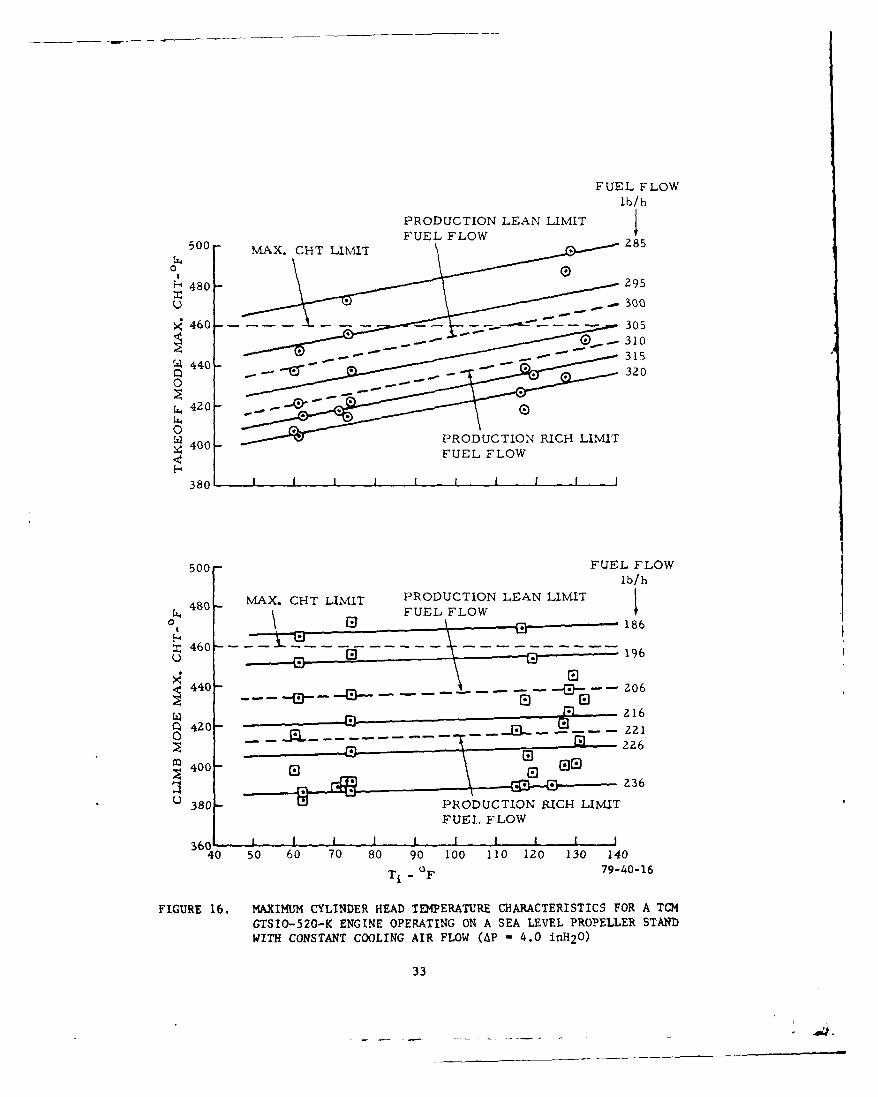
16 Maximum Cylinder Head Temperature Characteristics for a 33
TCM GTSIO-520-K Engine Operating on a Sea Level PropellerStand with Constant Cooling Air Flow (AP = 4.0 inH20)
LIST OF TABLES
Table Page
1 TCM GTSIO-520-K Engine 2
2 EPA Five-Mode LTO Cycle 7
3 FAA/NAFEC Seven-Mode LTO Cycle 9
4 Maximum Five-Mode LTO Cycle 9
5 Minimum Five-Mode LTO Cycle 10
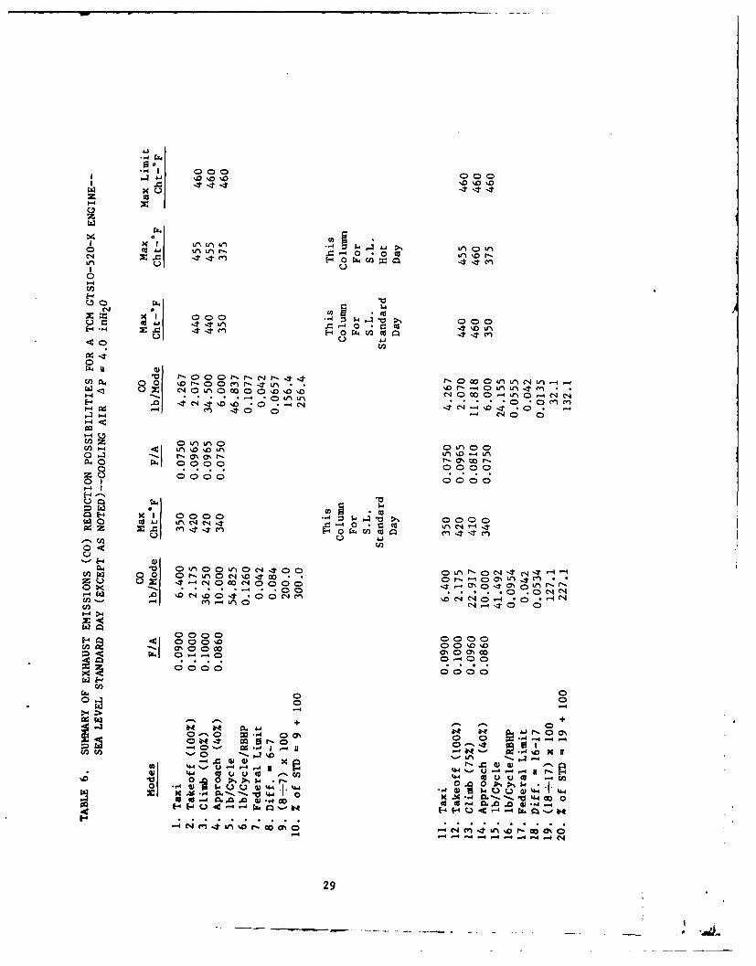
6 Summary of Exhaust Emissions (CO) Reduction Possibilities 29for a TCM GTSIO-520-K Engine--Sea Level Standard Day(Except as Noted)-Cooling Air AP=4.0 inH 20
v
.4,
INTRODUCTION
PURPOSE.
General aviation piston engine exhaust emission tests were conducted at theNational Aviation Facility Experim~ental Center (NAFEC) for the followingreasons:
1. Determine and establish total exhaust emissions characteristics for arepresentative group of current production general aviation piston engines.
2. Determine the effects of leaning-out of the fuel metering system onexhaust emissions.
3. Verify the acceptability of test procedures, testing techniques, instru-mentation, etc.
4. Determine reductions in operating limits and safety margins resultingfrom fuel system adjustments/modifications evaluated for improved pistonengine exhaust emissions characteristics.
BACKGROUND.
Beginning in 1967, Congress enacted a series of laws which added environmentalconsiderations to the civil aviation safety, control, and promotional functionsof the Federal Aviation Administration (FAA). This legislation was in responseto the growing public concern over environmental degradation. Thus, the FAAwas committed to the development, evaluation, and execution of programsdesigned to identify and minimize the undesirable environmental effects attri-butable to aviation.
In accordance with the Clean Air Act Amendments of 1970, the EnvironmentalProtection Agency (EPA) established emission standards and outlined test pro-cedures when it issued EPA rule part 87 in January 1973. The Secretary ofTransportation, and therefore the FAA, was charged with the responsibility forissuing regulations to implement this rule and enforcing these standards.
Implementation of this rule was contingent on the FAA's finding that safetywas not impaired by whatever means was employed to achieve the standards. Forthis reason, the FAA undertook a program, subsequent to the issuance of the EPAemission standards in July 1973, to determine the feasibility of implementation,verify test procedures, and validate test results.
There was concern that the actions suggested in order to comply with the EPAemission standards, such as operating engines at leaner mixture settings dur-ing landing and takeoff cycles, might compromise safety and/or significantlyreduce engine operating marging. Therefore, the FAA contracted with AvcoLycoming and Teledyne Continental Motors (TCM) to select engines that they con-sidered typical of their production, test these engines as normally produced
to establish a baseline emissions data base, and then alter (by lean-outadjustments) the fuel schedule and ignition timing to demonstrate methods bywhich the proposed EPA limits could be reached. In the event that hazardous
operating conditions were indicated by the manufacturer's tests, independentverification of data would be necessary. Therefore, it was decided to
duplicate the manufacturer's tests at NAFEC to provide the needed verifica-tion and expand the emissions data base through independent testing.
This report presents the NAFEC test results for the Teledyne ContinentalMotors (TCM) GTSIO-520-K piston engine (S/N220015). It should be noted thatsince the time of these tests, the EPA has rescinded the promulgated pistonengine standards (reference 1). This work is reported upon herein in thesame light as it would have been if the requirements were still in effect.
DISCUSSION
DESCRIPTION OF TELEDYNE CONTINENTAL MOTORS GTSIO-520-K ENGINE.
The GTSIO-520-K engine tested at NAFEC is a turbo supercharged fuel injected,horizontally opposed engine with a nominal 520 cubic inch displacement (cid),rated at 435 brake horsepower (bhp) for a nominal brake specific fuel consump-tion (bsfc) of 0.70. This engine is designed to operate on 100/130 octaneaviation gasoline (appendix A-Fuel Sample Analyzis of NAFEC Test Fuel).The vital statistics for this engine are provided in table 1.
TABLE 1. TCM GTSIO-520-K ENGINE
No. of Cylinders 6
Cylinder Arrangement HOMax. Engine Takeoff Power (HP, RPM) 435,3400Bore and Stroke (in.) 5.25 x 4.00
Displacement (cu. in.) 519.54Weight, Dry (lbs)--Basic Engine 614Propeller Drive GearedFuel Grade--Octane Rating 100/130Compression Ratio 7.5:1Max. Cylinder Head Temperature Limit (OF) 460Max. Allowable Exhaust Gas Temperature (OF) 1650
Drive Ratio 0.67:1
DESCRIPTION OF TEST SET-UP AND BASIC FACILITIES.
For the NAFEC sea level static tests, the engines were installed in the pro-peller test stand shown in figures 1 and 2. This test stand was located in
the NAFEC General Aviation Piston Engine Test Facility. The test facilityprovided the following capabilities for testing light aircraft pistonengines:
2
COOLING AkIR SYSE
EXHIAUST PIPE
! \ULSSION SAMPLE-
FIGURE 1. SEA LEVEL PROPELLER TEST STAND--TCM GTSIO-520-K PISTONENGINE INSTALLATION--EMISSIONS TESTING
3
FA
41-
'-4
AA
FH
144
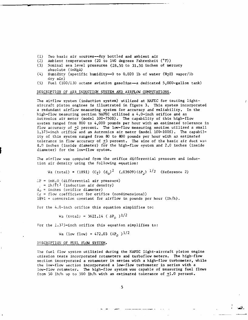
(1) Two basic air sources--dry bottled and ambient air(2) Ambient temperatures (20 to 140 degrees Fahrenheit (OF))(3) Nominal sea level pressures (28.50 to 31.50 inches of mercury
absolute (inHgA)(4) Humidity (specific humidity-O to 0.020 lb of water (H20) vapor/lb
dry air)(5) Fuel (100/130 octane aviation gasoline-a dedicated 5,000-gallon tank)
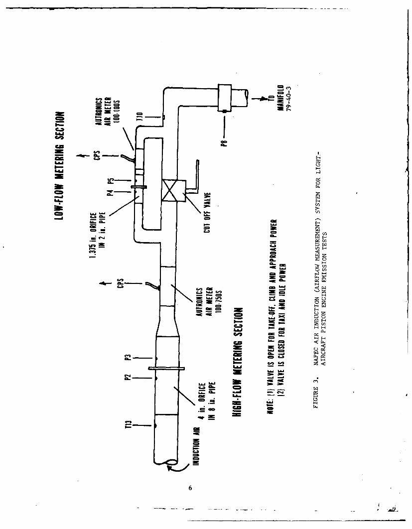
DESCRIPTION OF AIR INDUCTION SYSTEM AND AIRFLOW COMPUTATIONS.
The airflow system (induction system) utilized at NAFEC for testing light-aircraft piston engines is illustrated in figure 3. This system incorporateda redundant airflow measuring system for accuracy and reliability. In thehigh-flow measuring section NAFEC utilized a 4.0-inch orifice and anAutronics air meter (model 100-750S). The capability of this high-flow
system ranged from 800 to 4,000 pounds per hour with an estimated tolerance inflow accuracy of +2 percent. The low-flow measuring section utilized a small1.375-inch orifice and an Autronics air meter (model IO0-100S). The capabil-ity of this system ranged from 80 to 800 pounds per hour with an estimatedtolerance in flow accuracy of +3 percent. The size of the basic air duct wa8.0 inches (inside diameter) for the high-flow system and 2.0 inches (insidediameter) for the low-flow system.
The airflow was computed from the orifice differential pressure and induc-tion air density using the following equation:
Wa (total) = (1891) (Cf) (do) 2 (.03609)(6PP) 1/2 (Reference 2)
'P = inHO (differential air pressure)
= lb/ft 3 (induction air density)do = inches (orifice diameter)Cf = flow coefficient for orifice (nondimensional)1891 = conversion constant for airflow in pounds per hour (lb/h).
For the 4.0-inch orifice this equation simplifies to:
Wa (total) = 3621.14 ( APO )1/2
For the 1.375-inch orifice this equation simplifies to:
Wa (low flow) = 472.03 (APp )1/2
DESCRIPTION OF FUEL FLOW SYSTEM.
The fuel flow system utilizied during the NAFEC light-aircraft piston engineemission tests incorporated rotameters and turboflow meters. The high-flowsection incorporated a rotameter in series with a high-flow turbometer, whilethe low-flow section incorporated a low-flow turbometer in series with alow-flow rotameter. The high-flow system was capable of measuring fuel flowsfrom 50 lb/h up to 500 lb/h with an estimated tolerance of +1.0 percent.
5
Id.w
C..V
ZE -
NO - CL.
cm -W
-a--cn
-4
CL.z--0 u
C-31- 1 a-4
m..J -03c
flo z uI.- _
L&I -- -
P- -4= 'a
= .6Lai
6= 01 o=L
La6 L
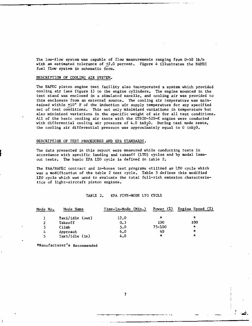
The low-flow system was capable of flow measurements ranging from 0-50 lb/hwith an estimated tolerance of +2.0 percent. Figure 4 illustrates the NAFECfuel flow system in schematic form.
DESCRIPTION OF COOLING AIR SYSTEM.
The NAFEC piston engine test facility also incorporated a system which providedcooling air (see figure 1) to the engine cylinders. The engine mounted in thetest stand was enclosed in a simulated nacelle, and cooling air was provided tothis enclosure from an external source. The cooling air temperature was main-tained within +100 F of the induction air supply temperature for any specifiedset of test conditions. This not only minimized variations in temperature butalso minimized variations in the specific weight of air for all test conditions.All of the basic cooling air tests with the GTSIO-520-K engine were conductedwith differential cooling air pressure of 4.0 inH20. During taxi mode tests,the cooling air differential pressure was approximately equal to 0 inH20.
DESCRIPTION OF TEST PROCEDURES AND EPA STANDARDS.
The data presented in this report were measured while conducting tests in
accordance with specific landing and takeoff (LTO) cycles and by modal lean-out tests. The basic EPA LTO cycle is defined in table 2.
The FAA/NAFEC contract and in-house test programs utilized an LTO cycle whichwas a modification of the table 2 test cycle. Table 3 defines this modifiedLTO cycle which was used to evaluate the total full-rich emission characteris-tics of light-aircraft piston engines.
TABLE 2. EPA FIVE-MODE LTO CYCLE
Mode No. Mode Name Time-In-Mode (Min.) Power (%) Engine Speed (%)
1 Taxi/idle (out) 12.0 * *
2 Takeoff 0.3 100 1003 Climb 5.0 75-1004 Approach 6.0 40 *5 Taxi/idle (in) 4.0 * *
*Manufacturer's Recommended
7
m
f4
I *I
C*
I.- ,- &i.cm - -m0
CD 4d
Lad fox
- m a :-Lhd
Li....m CD~
CD-d09
,-
Im I m
~ I.&ad
hi.'
-I
C.,(
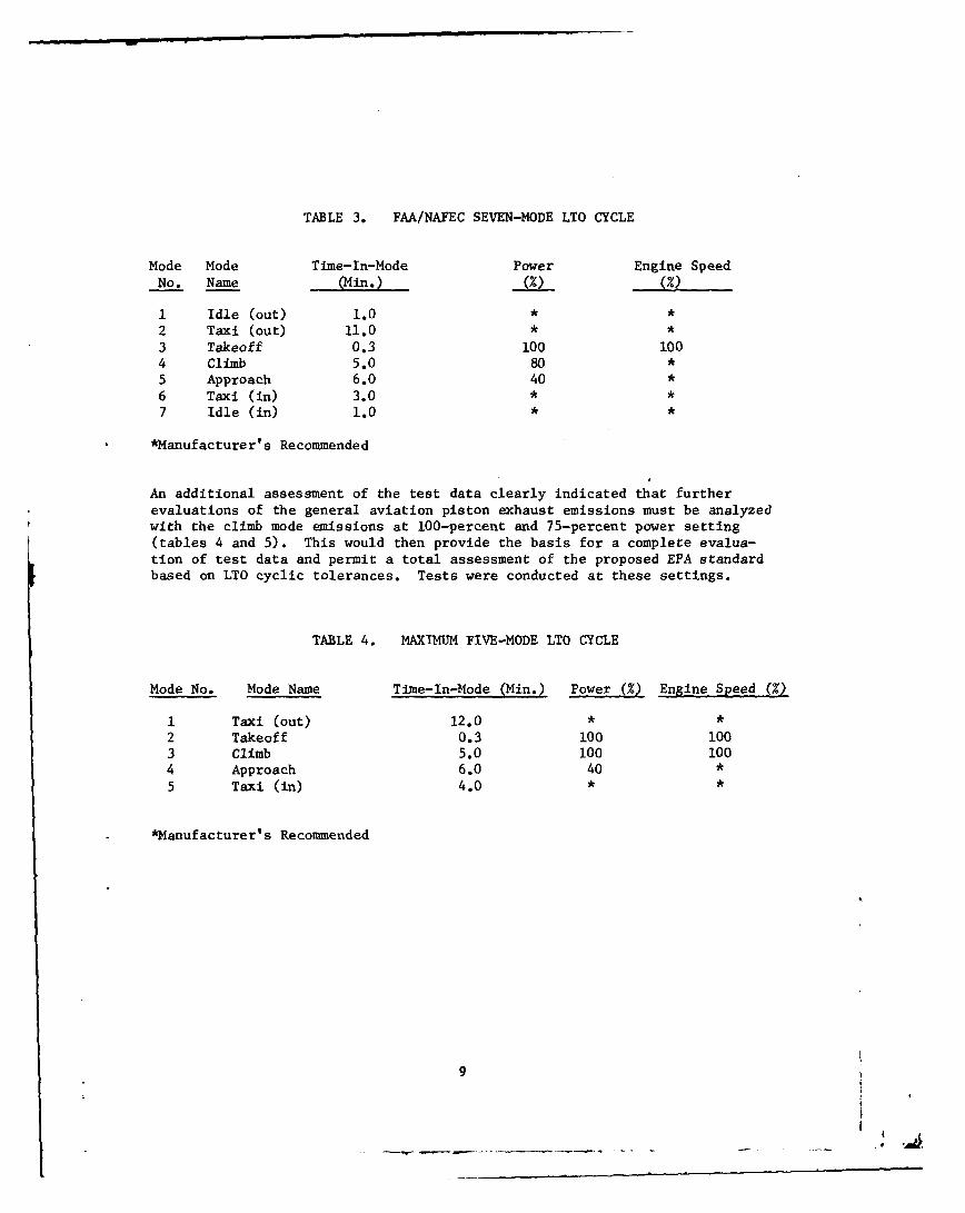
TABLE 3. FAA/NAFEC SEVEN-MODE LTO CYCLE
Mode Mode Time-In-Mode Power Engine SpeedNo. Name (Min.) (%) (%)
1 Idle (out) 1.0 * *2 Taxi (out) 11.0 * *3 Takeoff 0.3 100 1004 Climb 5.0 80 *5 Approach 6.0 40 *6 Taxi (in) 3.0 * *
7 Idle (in) 1.0 * *
*Manufacturer's Recommended
An additional assessment of the test data clearly indicated that furtherevaluations of the general aviation piston exhaust emissions must be analyzedwith the climb mode emissions at 100-percent and 75-percent power setting(tables 4 and 5). This would then provide the basis for a complete evalua-tion of test data and permit a total assessment of the proposed EPA standardbased on LTO cyclic tolerances. Tests were conducted at these settings.
TABLE 4. MAXIMUM FIVE-MODE LTO CYCLE
Mode No. Mode Name Time-In-Mode (Min.) Power (%) Engine Speed ()
1 Taxi (out) 12.0 * *2 Takeoff 0.3 100 1003 Climb 5.0 100 1004 Approach 6.0 40 *5 Taxi (in) 4.0 * *
*Manufacturer' s Recommended
9
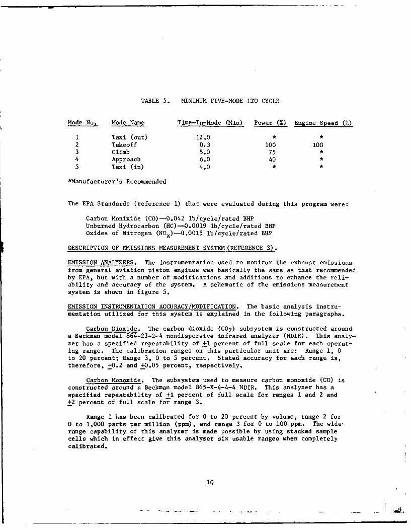
TABLE 5. MINIMUM FIVE-MODE LTO CYCLE
Mode No. Mode Name Time-In-Mode (Min) Power (%) Engine Speed (%)
1 Taxi (out) 12.0 * *2 Takeoff 0.3 100 1003 Climb 5.0 75 *4 Approach 6.0 40 *5 Taxi (in) 4.0 * *
*Manufacturer's Recommended
The EPA Standards (reference 1) that were evaluated during this program were:
Carbon Monixide (CO)-0.042 lb/cycle/rated BHPUnburned Hydrocarbon (HC)--O.0019 lb/cycle/rated BHPOxides of Nitrogen (NOx)-0.0015 lb/cycle/rated BHP
DESCRIPTION OF EMISSIONS MEASUREMENT SYSTEM (REFERENCE 3).
EMISSION ANALYZERS. The instrumentation used to monitor the exhaust emissions
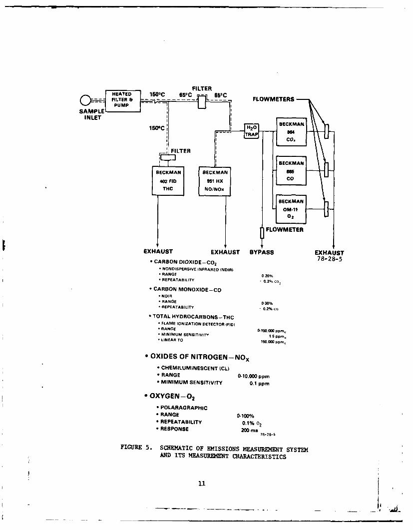
from general aviation piston engines was basically the same as that recommendedby EPA, but with a number of modifications and additions to enhance the reli-ability and accuracy of the system. A schematic of the emissions measurementsystem is shown in figure 5.
EMISSION INSTRUMENTATION ACCURACY/MODIFICATION. The basic analysis instru-mentation utilized for this system is explained in the following paragraphs.
Carbon Dioxide. The carbon dioxide (C02) subsystem is constructed arounda Beckman model 864-23-2-4 nondispersive infrared analyzer (NDIR). This analy-zer has a specified repeatability of +1 percent of full scale for each operat-ing range. The calibration ranges on this particular unit are: Range 1, 0to 20 percent; Range 3, 0 to 5 percent. Stated accuracy for each range is,therefore, +0.2 and +0.05 percent, respectively.
Carbon Monoxide. The subsystem used to measure carbon monoxide (CO) isconstructed around a Beckman model 865-X-4-4-4 NDIR. This analyzer has aspecified repeatability of +1 percent of full scale for ranges 1 and 2 and±2 percent of full scale for range 3.
Range 1 has been calibrated for 0 to 20 percent by volume, range 2 for0 to 1,000 parts per million (ppm), and range 3 for 0 to 100 ppm. The wide-range capability of this analyzer is made possible by using stacked samplecells which in effect give this analyzer six usable ranges when completelycalibrated.
10
FILTERFLOWMETER
*~R 8AGE0-4
F EEAILTY2%R
BCRBON MOOIECOMA
*E NNIR
* RANGEC0MAN
* TOA RCARBON S -THCE- 7-2-- FLAMPSIE IOIINFRDETCO IDI- RANGE O1020%Op- MINIMMA SEIIITY 0.2%Cpm2
0 LNARBO TON150.00 pp
- OXIDE OF ITOGE%* CREETAILINEEN 0.2%c
*RANE 0-0000 p*MINIMUM SENSITIVITY 0.1 pp m
a OXYGEN-02
e POLARAGRAPHIC* RANGE 0-100%0 REPEATABILITY 0.1% 02* RESPONSE 200 ms
78-28-6
FIGURE 5.* SCHEMATIC OF EMISSIONS MEASUREMENT SYSTEMAND ITS M4EASUREMENT CHARACTERISTICS
Effects of interfering gases, such as C02 and water vapor, were deter-mined and reported by the factory. Interferences from 10 percent C02 weredetermined to be 12 ppm equivalent CO, and interferences from 4 percent watervapor were determined to be 6 ppm CO equivalent. Even though the interferencefrom water vapor is negligible, a condenser is used in the CO/CO2 subsystem toeliminate condensed water in the lines, analyzers, and flowmeters. This con-densation would have decreased analyzer sensitivity and necessitated more fre-quent maintenance if it had been eliminated.
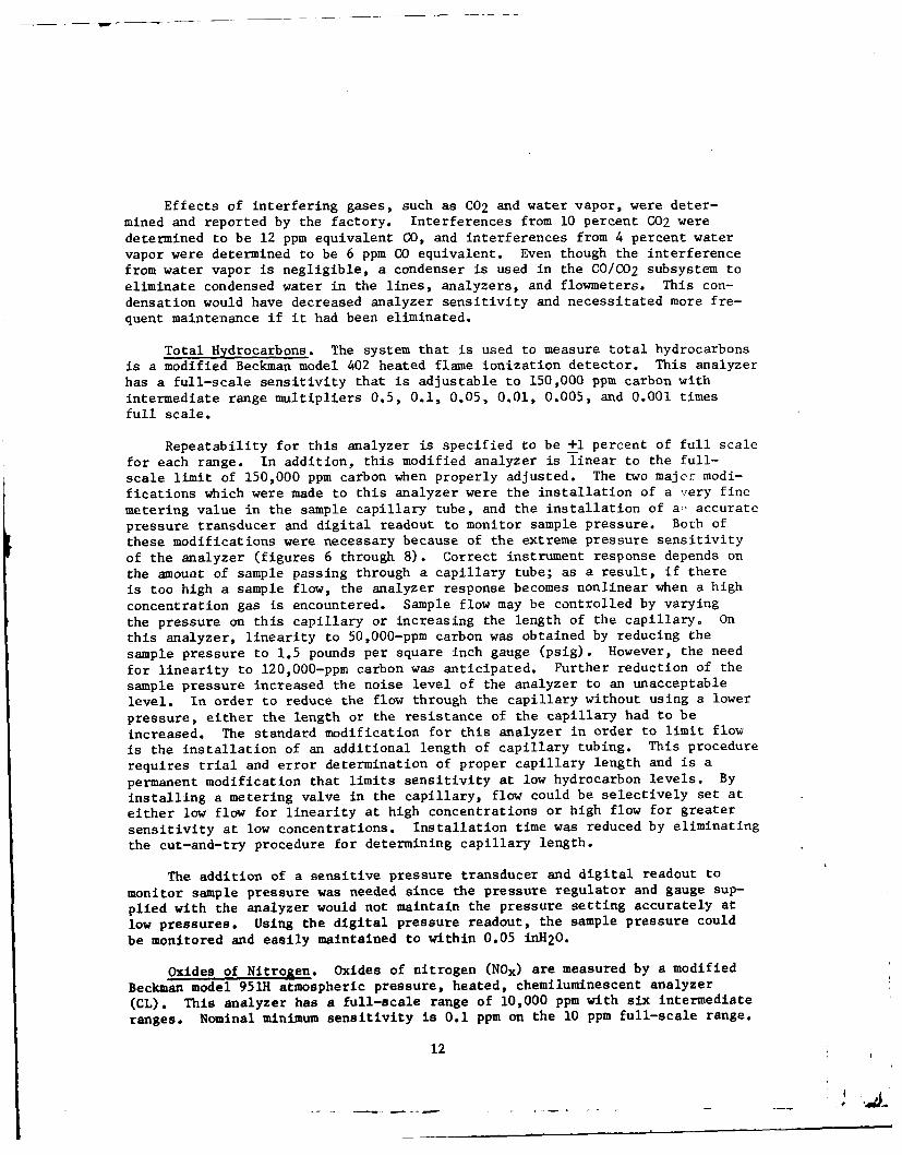
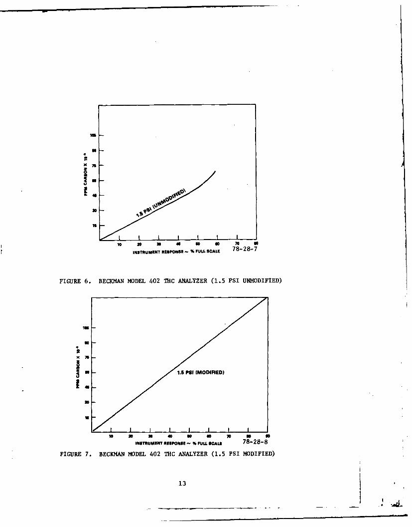
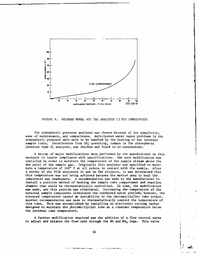
Total Hydrocarbons. The system that is used to measure total hydrocarbonsis a modified Beckman model 402 heated flame ionization detector. This analyzerhas a full-scale sensitivity that is adjustable to 150,000 ppm carbon withintermediate range multipliers 0.5, 0.1, 0.05, 0.01, 0.005, and 0.001 timesfull scale.
Repeatability for this analyzer is specified to be +1 percent of full scalefor each range. In addition, this modified analyzer is linear to the full-scale limit of 150,000 ppm carbon when properly adjusted. The two majo'r modi-fications which were made to this analyzer were the installation of a very finemetering value in the sample capillary tube, and the installation of a;, accuratepressure transducer and digital readout to monitor sample pressure. Both ofthese modifications were necessary because of the extreme pressure sensitivityof the analyzer (figures 6 through 8). Correct instrument response depends onthe amount of sample passing through a capillary tube; as a result, if thereis too high a sample flow, the analyzer response becomes nonlinear when a highconcentration gas is encountered. Sample flow may be controlled by varyingthe pressure on this capillary or increasing the length of the capillary. Onthis analyzer, linearity to 50,000-ppm carbon was obtained by reducing thesample pressure to 1.5 pounds per square inch gauge (psig). However, the needfor linearity to 120,000-ppm carbon was anticipated. Further reduction of thesample pressure increased the noise level of the analyzer to an unacceptablelevel. In order to reduce the flow through the capillary without using a lowerpressure, either the length or the resistance of the capillary had to beincreased. The standard modification for this analyzer in order to limit flowis the installation of an additional length of capillary tubing. This procedurerequires trial and error determination of proper capillary length and is apermanent modification that limits sensitivity at low hydrocarbon levels. By
installing a metering valve in the capillary, flow could be selectively set ateither low flow for linearity at high concentrations or high flow for greatersensitivity at low concentrations. Installation time was reduced by eliminatingthe cut-and--try procedure for determining capillary length.
The addition of a sensitive pressure transducer and digital readout to
monitor sample pressure was needed since the pressure regulator and gauge sup-plied with the analyzer would not maintain the pressure setting accurately atlow pressures. Using the digital pressure readout, the sample pressure couldbe monitored and easily maintained to within 0.05 inH2O.
Oxides of Nitrogen. Oxides of nitrogen (Nox) are measured by a modifiedBeckman model 951H atmospheric pressure, heated, chemiluminescent analyzer(CL). This analyzer has a full-scale range of 10,000 ppm with six intermediateranges. Nominal minimum sensitivity is 0.1 ppm on the 10 ppm full-scale range.
12
15
Un
0
x 7
30
S
0 40 a o I1 7INSTRUMENT RESPONSE ~ % FULL SCALE 728-28-
FIGURE 7. BECKMAN MODEL 402 THC ANALYZER (1.5 PSI UMODIFIED)
3"3
so
0 20 0 40 U 5 70 5
IIS~hMENT RESPONE - %, PULL SCAE 7-8-72-
FIGURE 6. BECKMAN MODEL 402 THC ANALYZER (1.5 PSI UMODIFIED)
I OU
II
in I 11
0
~46
30 - ~ 3 PSI (UNMODIFIED)
16
I I10 20 30 40 50 60 70 so 90 100
INSTRUMENT RESPONSE -% FULL SCALE 78-28-9
FIGURE 8. BECKMAN MODEL 402 THC ANALYZER (3 PSI UNMODIFIED)
The atmospheric pressure analyzer was chosen because of its simplicity,ease of maintenance, and compactness. Anticipated water vapor problems in theatmospheric pressure unit were to be handled by the heating of the internalsample train. Interference from C02 quenching, common in the atmosphericpressure type CL analyzer, was checked and found to be nonexistent.
A series of major modifications were performed by the manufacturer on thisanalyzer to insure compliance with specifications. One such modification wasinstalled in order to maintain the temperature of the sample stream above thedew point of the sample gas. Originally this analyzer was specified to main-tain a temperature of 1400 F at all points in contact with the sample. Aftera survey of the 95111 analyzers in use on FAA projects, it was determined thatthis temperature was not being achieved because the method used to heat thecomponents was inadequate. A recommendation was made to the manufacturer toinstall a positive method of heating the sample tube compartment and reactionchamber that would be thermostatically controlled. In time, the modificationwas made, and this problem was eliminated. Increasing the temperature of theinternal sample components eliminated the condensed water problem; however, theelevated temperature caused an instability in the photomultiplier tube output.Another recommendation was made to thermostatically control the temperature ofthis tube. This was accomplished by installing an electronic cooling jacketdesigned to maintain the photomultiplier tube at a constant temperature belowthe internal case temperature.
A further modification required was the addition of a flow control valveto adjust and balance the flow rate through the NO and NOx legs. This valve
14
replaced a restrictor clamp that was used by the manufacturer to set the NO toNOx flow balance. The problem that was encountered with this clamp was that itwas not a positive method of adjusting the restriction on the capillary. Theclamp compression was affected by the flexible material on which the clamp wasmounted and the variable flexibility of the Teflon capillary as it was heated.This caused the restriction on the capillary to change with time and causedpermanent deformation of the capillary allowing only an adjustment that wouldincrease the restriction.
Oxygen Measurement. Oxygen (02) was measured by a Beckman model OM-11oxygen analyzer. This analyzer uses a polagraphic type sensor unit to measureoxygen concentration. An advanced sensor and amplification system combine togive an extremely fast response and high accuracy. Specified response for90 percent of final reading is less than 200 milliseconds (ms) with an accuracyof less than +0.1-percent 02. The range of this unit is a fixed 0 to 100 per-cent 02 concentration.
EMISSIONS INSTRUMENTATION MODIFICATION STATUS DURING THE TESTING OF THEGTSIO-520-K ENGINE. The tests conducted with the TCM GTS!fO-520-K engine uti-lized the Beckman model OM-11 oxygen (02) analyzer and a prototype Beckmanmodel 951H oxides of nitrogen (NOx) analyzer.
All of the emissions and exhaust constituent-measuring instruments/analyzersincorporated the latest specified modifications described in this report.
DESCRIPTION OF SAMPLE HANDLING SYSTEM.
Exhaust samples are transported to the analysis instrumentation under pressurethrough a 35-foot-long, 3/8-inch o.d., heated, stainless steel sample line.The gas is first filtered and then pumped through this line by a heated MetalBellows model MB-158 high temperature stainless steel sample pump. The pump,filter, and line are maintained at a temperature of 3000 +4* F to prevent con-densation of water vapor and hydrocarbons. At the instrument console, thesample is split to feed the hydrocarbon, oxides of nitrogen, and CO/CO2/02subsystems which require different temperature conditioning. The sample gasto the total hydrocarbon subsystem is maintained at 3000 F while the tempera-ture of remaining sample gas to the NOx and CO/CO2/02 system is allowed todrop to 1500 F. Gas routed to the oxides of nitrogen subsystem is then main-tained at 1500 F, while the gas to the CO/C02/02 subsystem is passed througha 320 F condenser to remove any water vapor present in the sample. Flow ratesto each analyzer are controlled by a fine-metering valve and are maintained atpredetermined values to minimize sample transport and system response time.Flow is monitored at the exhaust of each analyzer by three 15-centimeter (cm)rotameters. Two bypasses are incorporated into the system to keep sampletransport time through the lines and condenser to a minimum without causingadverse pressure effects in the analyzers.
DESCRIPTION OF FILTRATION SYSTEM.
Particulates are removed from the sample at three locations in the system,thereby minimizing downtime due to contaminated sample lines and analyzers(figure 5). Upstream of the main sample pump is a heated clamshell-type stain-less steel filter body fitted with a Whatman GF/C glass fiber paper filterelement capable of retaining particles in the 0.1 micron range. A similar
15
filter is located in the total hydrocarbon analyzer upstream of the samplecapillary. A Mine Safety Appliances (MSA) type H ultra filter capable ofretaining 0.3 micron particles is located at the inlet to the oxides of nitrogenand CO/C02 /02 subsystems.
COMPUTATION PROCEDURES.
The calculations required to convert exhaust emission measurements into massemissions are the subject of this section.
Exhaust emission tests were designed to measure CO2 , CO, unburned hydrocarbons(HC), NOx, and exhaust excess 02 concentrations in percent or ppm by volume.Mass emissions were determined through calculations utilizing the data obtainedduring the simulation of the aircraft LTO cycle and from modal lean-out data.
COMBUSTION EQUATION. The basic combustion equation can be expressed very simply:
Fuel + Air = Exhaust Constituents
An initial examination of the problem requires the following simplifyi!ngassumptions:
1. The fuel consists solely of compounds of carbon and hydrogen.
2. The air is a mixture of oxygen and inert nitrogen in the volumetric ratioof 3.764 parts apparent nitrogen to 1.0 part oxygen (see appendix B foradditional details).
3. If a stoichiometric combustion process exists, the fuel and air are sup-plied in chemically correct proportions.
4. The fuel (which consists usually of a complex mixture of hydrocarbons)can be represented by a single hydrocarbon having the same carbon-hydrogenratio and molecular weight as the fuel; usually C8H17 as an average fuel.
Applying the above assumptions for stoichiometric conditions, a useful generalreaction equation for hydrocarbon fuel is:
MfC8HI7 + Ma (02 + 3.764N2 + MwH2O)+ MIC02 + M3H 20 + M5N2 (1)S0(References 4 and 5)
Where Mf = Moles of FuelMa = Moles of Air or OxygenMl = Moles of Carbon Dioxide (C02)M3 = Moles of Condensed Water (H20)M 5 = Moles of Nitrogen (N2) - Exhaust
3.764Ma = Moles of Nitrogen (N2) - In AirMaMw - Moles of Humidity (H20) - In Air
The above equation is applicable to dry air when Mw is equal to zero.
16
From equation (1), and assuming dry air with one mole of fuel (Mf=l.0), thestoichiometric fuel-air ratio may be expressed as:
(F/A)s = Wt. Fuel = 12.011 (8) + 1.008 (17) (2)Wt. Air Required 12.25 [32.000 + 3.764(28.161)
(F/A)s = 113.224 = 0.06712.25(137.998)
The mass carbon-hydrogen ratio of the fuel may be expressed as follows:
C/H = 12.001(8) = 96.088 = 5.607 (3)1.008(17) 17.136
The atomic hydrogen-carbon ratio is:
17/8 = 2.125 (4)
The stoichiometric fuel-air ratio may be expressed as a function of the masscarbon-hydrogen ratio of the fuel. The derivation of this equation ispresented in reference 4.
(F/A)s = C/H + 1 (5)
ll.5(C/+3)
(F/A)s = 0.067 for a mass carbon-hydrogen ratio of 5.607
With rich (excess fuel) mixtures, which are typical for general aviation pistonengines, some of the chemical energy will not be liberated because there isnot enough air to permit complete oxidation of the fuel. Combustion under suchconditions is an involved process. By making certain simplifying assumptionsbased on test results, the effect of rich mixtures may be calculated withreasonable accuracy.
For rich (excess fuel) mixtures, equation (1) will now be rewritten to express
the effects of incomplete combustion:
MfC 8H1 7 + Ma(0 2 + 3.764N2 + M4wH20) - MlC02 + M2 CO + M 3H20 + M 4H 2 +
M5N2 + M6NO + M7CH4 + M802 + M9 C (6)
Since only a limited number of the exhaust constituents were measured duringthe testing of general aviation piston engines, the above equation can only besolved by applying certain expeditious assumptions and emperical data.
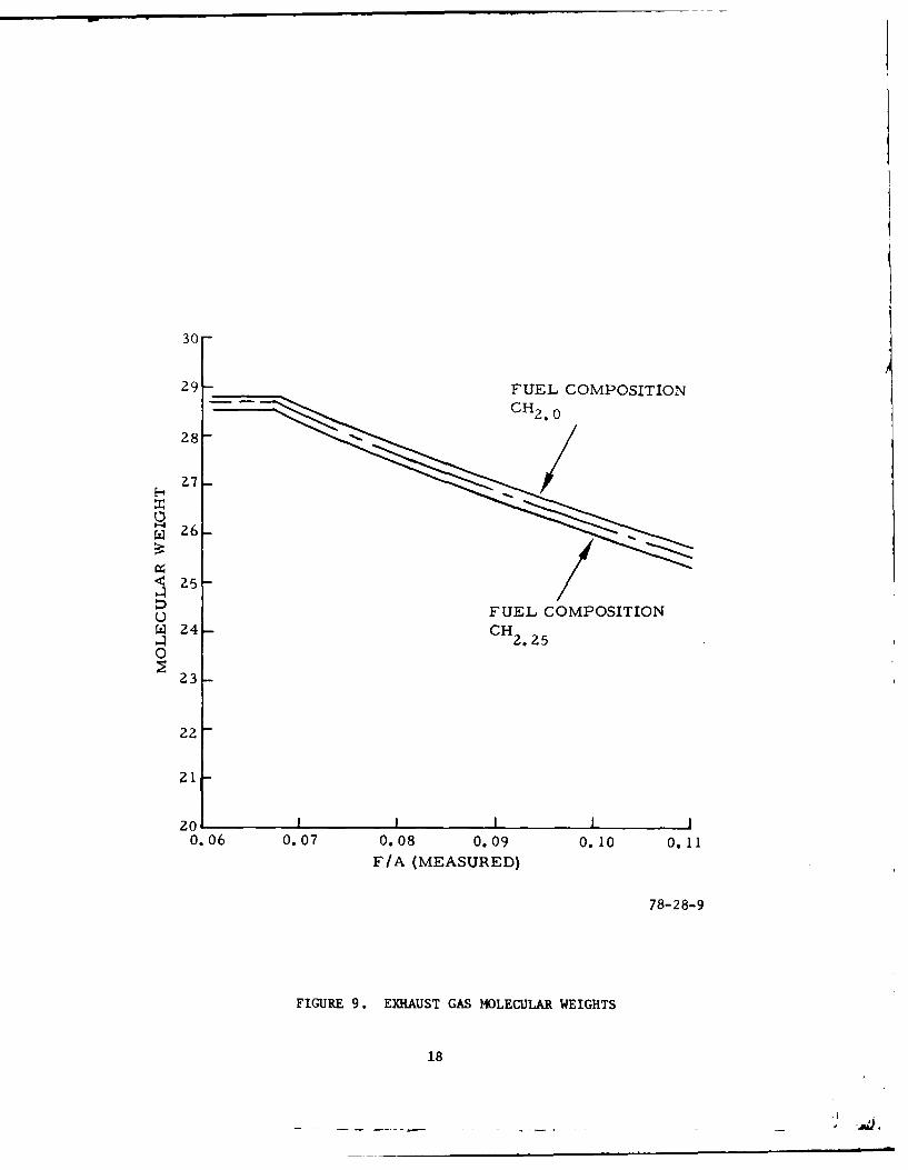
An important requirement was the accurate measurement of air and fuel flows.
These parameters provide the data for determining engine mass flow (Wm), andwith the aid of figure 9 (developed from reference 6), it is a simple computa-tion to calculate the total moles (Mtp) of exhaust products being expelled bygeneral aviation piston engine.
17
30-
29- FUEL COMPOSITION
28-
27
u FUEL COMPOSITION
.4H 2 . 2 5
0
23
22
21-
200.06 0.07 0.08 0.09 0.10 0.11
F/A (MEASURED)
78-28-9
FIGURE 9.* EXHAUST GAS MOLECULAR WEIGHTS
18
(MItp) = Wm (engine mass flow) + (exh. mol. wt) (7)
Since the unburned hydrocarbons (HC) and oxides of nitrogen (NOx) are measuredwet, it becomes a very simple matter to compute the moles of HC and NOx thatare produced by light-aircraft piston engines.
M7 (Moles of HC) =(ppm t 106) x Mtp (8)
M6 (Moles of NOx ) =(ppm - 106) x Mtp (9)
If the dry products (Mdp) of combustion are separated from the total exhaustproducts (Mtp), it is possible to develop a partial solution for five ot theproducts specified in equation 6.
This can be accomplished as follows:
The summation of the mole fractions (MF)d for dry products is
ml + m 2 + m4 + m5 + m8 = 1.0000 (10)
ml = 1F(CO2) = %C02 (measured dry), expressed as a fraction
m2 - MF(CO) = %CO (measured dry), expressed as a fraction
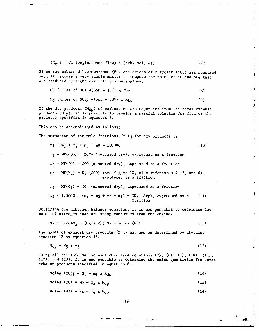
m4 = MF(H2) - K4 (%CO) (see figure 10, also references 4, 5, and 6),expressed as a fraction
m8 = MF(0 2) = %02 (measured dry), expressed as a fraction
m5 = 1.0000 - (mI + m2 + m4 + m8) = %N2 (dry), expressed as a (11)fract ion
Utilizing the nitrogen balance equation, it is now possible to determine the
moles of nitrogen that are being exhausted from the engine.
M5 = 3.764Ma - (M6 + 2); M 6 = moles (NO) (12)
The moles of exhaust dry products (Mdp) may now be determined by dividingequation 12 by equation 11.
Mdp - M 5 + m5 (13)
Using all the information available from equations (7), (8), (9), (10), (11),(12), and (13), it is now possible to determine the molar quantities for sevenexhaust products specified in equation 6.
Moles (C02) l M l n1 x Mdp (14)
Moles (CO) , M2 M m2 x Mdp (15)
Moles (H2) - M4 m4 x Mdp (15)
19
CH 2 . 1 2 CH 2 o 1 9 CH 2. 2 614-
13
12
F u7
w 11 6 7 8 9 1
HYROEN PE1N0YVLUE 7-81
0
>
z
03
2
05
0 4 6 7 8 9 1
22
Moles (N2) = M5 - m5 x Mdp (17)
Moles (02) = M8 - m8 x Mdp (18)
Moles (CH 4 ) = M7 = (ppm + 106) x Mtp (19)
Moles (NO) = M6 - (ppm + 106) x Mtp (20)
To determine M3 (moles of condensed H20), it is now appropriate to apply the
oxygen balance equation.
M3 = Ma (2 + Mw ) - (21 + M2 + M6 + 2M8) -Moles (20) (.21)
The remaining constituent specified in equation 6 may now be determined from
the carbon balance equation 22.
Mg = 8M f - (M1 + M2 + M 7) (22)
A check for the total number of exhaust moles (Mtp), calculated from equation
9, may now be determined from equation 23.
Mtp Ml + M2 + M3 + M4 + M5 + M6 + M7 + M + M9 (23)
ii + m2 + m3
+ m4 + 5 + m6 + m 7
+ 18 + ;9 1.0000 (24)
11 - MF(C02) = i M tp
;2 = MF(CO) = M2 + Mtp
;n3 = MF(H20)
= M3 t Mtp
rn4 = M(H 2 ) = M4 + Mtp
m5 - MF(N 2) = M5 t Mtp
m6 = MH(NO) m M6 + Mtp
m7 - MF(CH4) = M7 * MtP
m8 = MF(O2) = M8 Mtp
9 F(C) = M9 + Mtp
The exhaust constituent mass flow rates may be computed in the following
manner using each exhaust constituents molar constant with the appropriate
molecular weight.
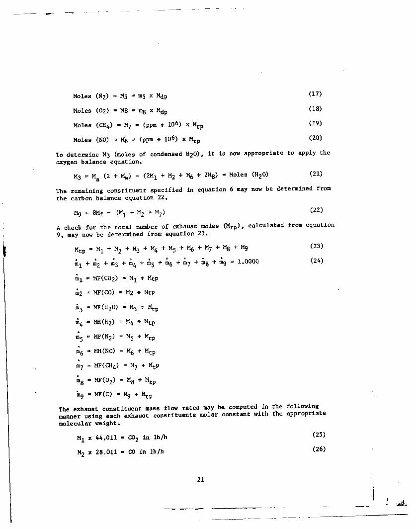
M1 x 44.011 - C02 in lb/h (25)
M2 x 28.011 - CO in lb/h (26)
21
M3 x 18.016 = H20 in lb/h (27)
M4 x 2.016 = H2 in lb/h (28)
M5 x 28.161 = N2 in lb/h (29)
M6 x 30.008 = NO in lb/h (30)
M7 x 16.043 = ZP-4 in lb/h (31)
M8 x 32.000 = 02 in lb/h (32)
M9 x 12.011 = C in lb/h (33)
The exhaust fuel flow (Wfe), based on exhaust constituents, can now becalculated on a constituent-by-constituent basis as follows:
(Ml + M2 + M9) x 12.011 = lb/h (34)
M7 x 16.043 = lb/h (35)
(M3 - MaMw ) + M4 x 2.016 (36)
Wfe (34) + (35) + (36) lb/h (37)
In a similar manner the exhaust airflow (Wae) can also be calculated on aconstituent-by-constituent basis:
M, x 32.000 = lb/h (38)
M2 x 16.000 = lb/h (39)
(M3 x 16.000) + (M aMw x 18.016) - b/h (40)
M5 x 28.161 l ib/h (41)
M6 x 30.008 = lb/h (42)
M8 x 32.000 = lb/h (43)
Wae - (38)+-+ (43) l ib/h (44)
Using equations (37) and (44) it is now possible to determine a calculatedfuel-air ratio on the basis of total exhaust constituents.
(F/A)calculated - (37) + (44) (45)
22
RESULTS
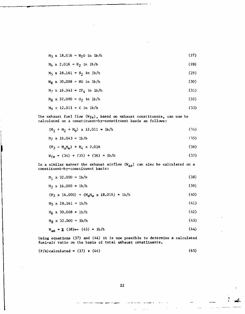
GENERAL COMMENTS.
General aviation pistion engine emission tests were conducted to provide thefollowing categories of data:
1. Full-rich (or production fuel schedule) baseline data for each powermode specified in the LTO test cycle.
2. Lean-out data for each power mode specified in the LTO test cycle.
3. Data for each power mode specified in the LTO test cycle utilized coolingairf low AP = 4.0 inU2O at takeoff, climb, and approach powers. Taxi/idle modecooling airflow A~P was approximately equal to zero.
RESULTS OF BASELINE TESTS (LANDING-TAKEOFF CYCLE EFFECTS).
Based on an analysis of the factors affecting piston engine emissions, it car.be shown that the mode conditions having the greatest influence on the grosspollutant levels produced by the combustion process are taxi, approach, andclimb, when using the LTO cycle defined in tables 3, 4, and 5. The five-modeLTO cycle shows that approximately 99 percent of the total cycle time(27.3-mmn) is attributed to these three modal conditions. Furthermore, thetaxi modes (both out and in) account for slightly less than 59 percent of thetotal cycle time. The remainder of the time is almost equally apportioned tothe approach and climb modes (22 and 18 percent, respectively).
As a result of these time apportionments, it was decided that an investigationand evaluation of the data should be undertaken to determine which mode(s) hasthe greatest influence on improving general aviation piston engine emissions.The subsequent sections of this report will show the exhaust emissions char-acteristics for a Teledyne Continental Motors (TCH) GTSIO-520-K engine(S,'N220015) and what improvements are technically feasible within the limitsof safe aircraft/engine operational requirements based on sea level propellertest stand evaluations conducted at NAFEC.
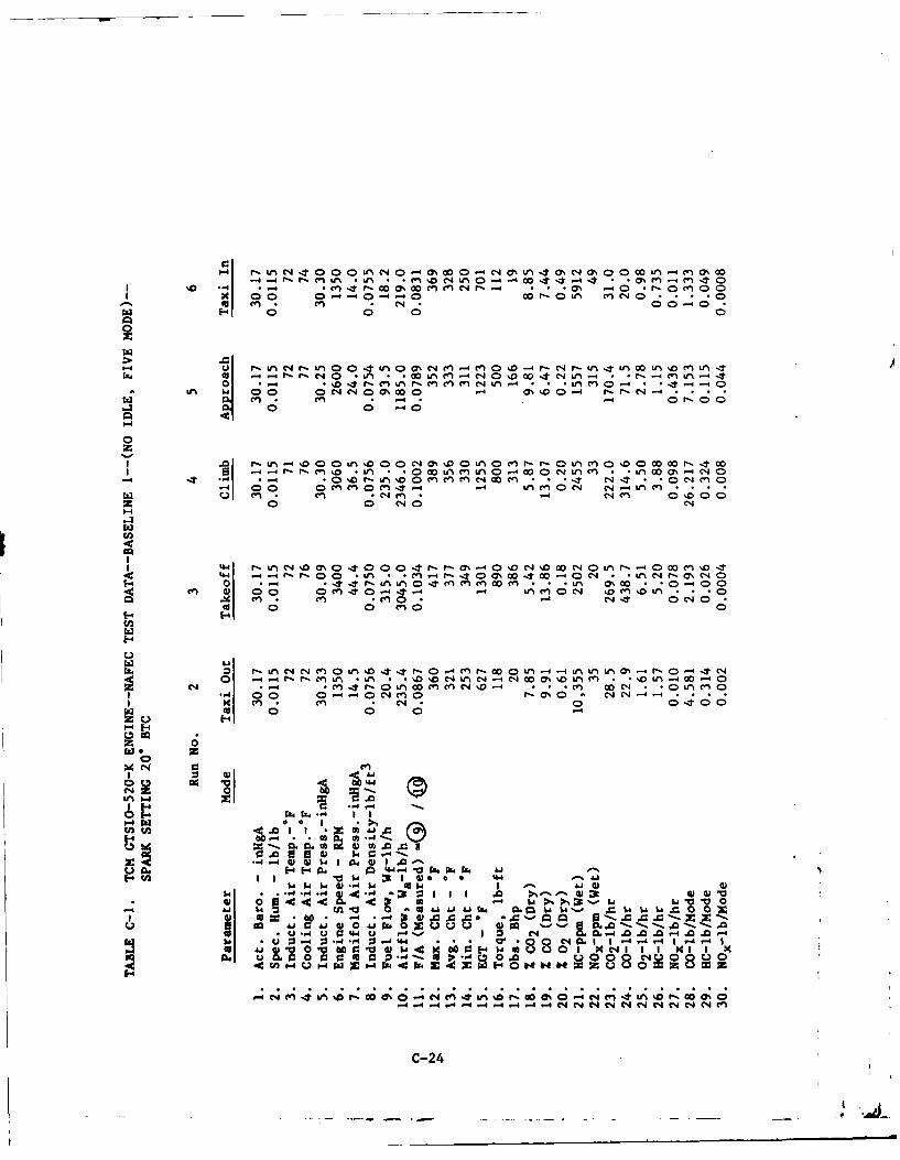
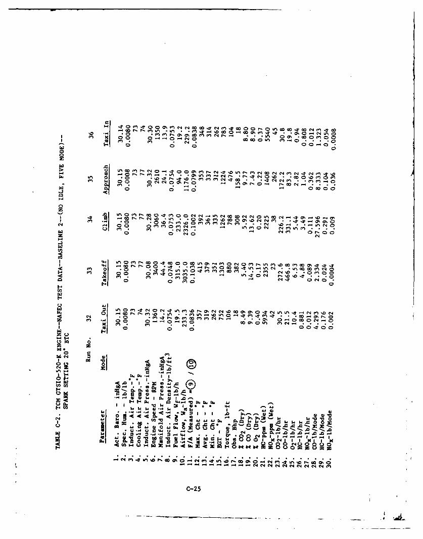
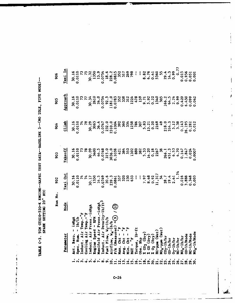
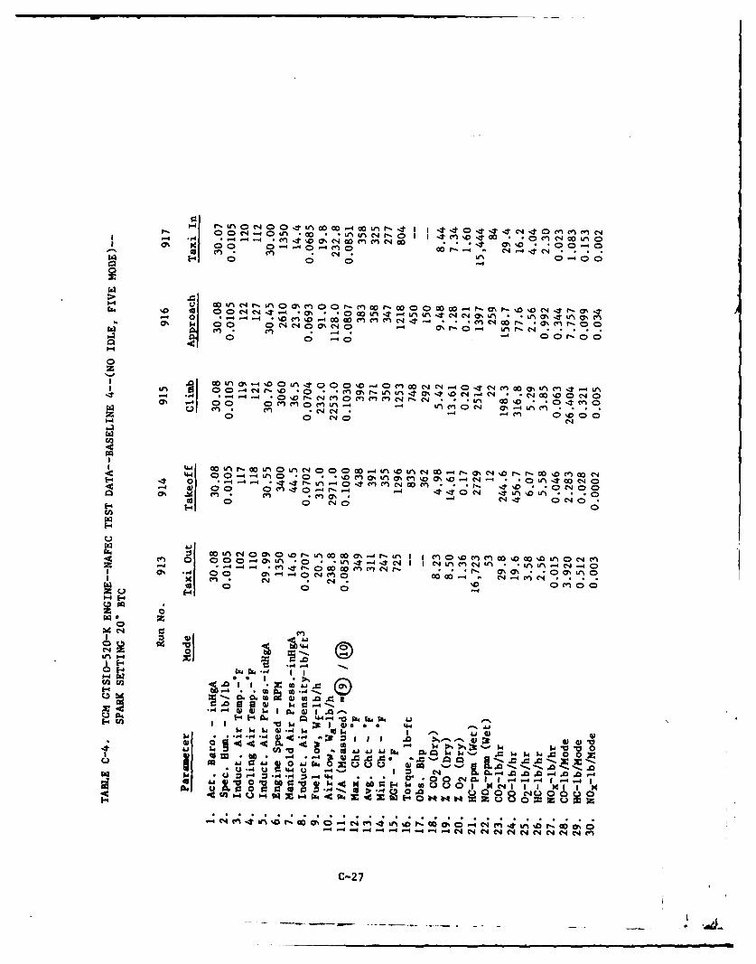
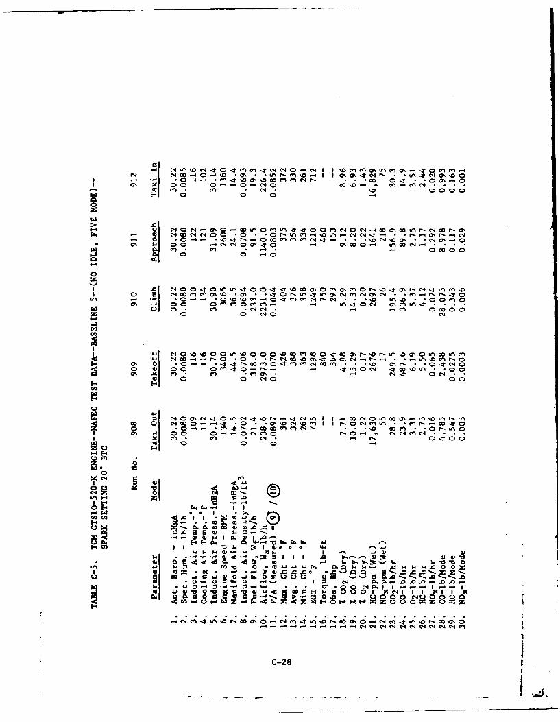
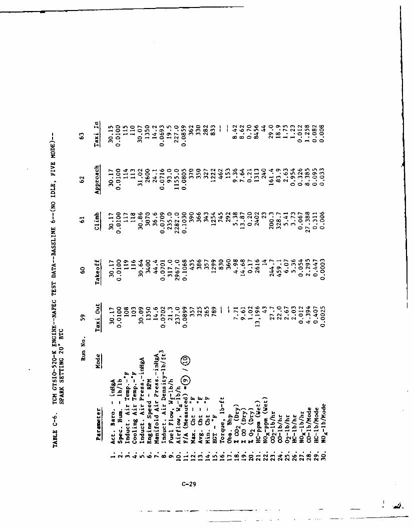
The first set of data to be presented and evaluated is the five-mode baselineruns conducted to establish the current production full-rich exhaust emissionscharacteristics of the GTSIO-520-K engine. These are summarized in tabularform in appendix C (see tables C-1 through C-20) and includes data that wereobtained for a range of sea level ambient conditions, specified as follows:
Induction air temperature (Ti) - 600 F to 1350 FCooling air temperature (Tc) - Ti ± 108 FInduction air pressure (Pi) -29.70 to 31.15 inHgAInduction air density (p) - 0.0680 to 0.0770 lb/ft3
23
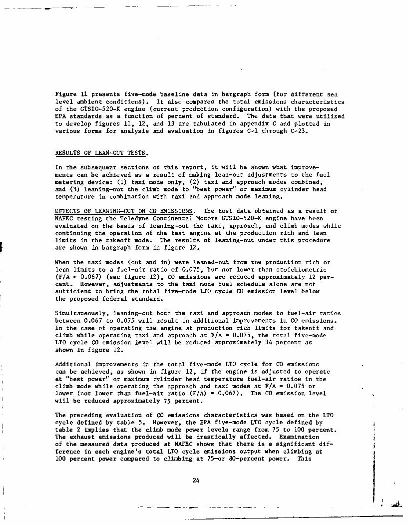
Figure 11 presents five-mode baseline data in bargraph form (for different sealevel ambient conditions). It also compares the total emissions characteristicsof the GTSIO-520-K engine (current production configuration) with the proposedEPA standards as a function of percent of standard. The data that were utilizedto develop figures 11, 12, and 13 are tabulated in appendix C and plotted invarious forms for analysis and evaluation in figures C-1 through C-23.
RESULTS OF LEAN-OUT TESTS.
In the subsequent sections of this report, it will be shown what improve-ments can be achieved as a result of making lean-out adjustments to the fuelmetering device: (1) taxi mode only, (2) taxi and approach modes combined,and (3) leaning-out the climb mode to "best power" or maximum cylinder headtemperature in combination with taxi and approach mode leaning.
EFFECTS OF LEANING-OUT ON CO EMISSIONS. The test data obtained as a result ofNAFEC testing the Teledyne Continental Motors GTSIO-520-K engine have beenevaluated on the basis of leaning-out the taxi, approach, and climb modes whilecontinuing the operation of the test engine at the production rich and leanlimits in the takeoff mode. The results of leaning-out under this procedureare shown in bargraph form in figure 12.
When the taxi modes (out and in) were leaned-out from the production rich orlean limits to a fuel-air ratio of 0.075, but not lower than stoichiometric(F/A = 0.067) (see figure 12), CO emissions are reduced approximately 12 per-cent. However, adjustments to the taxi mode fuel schedule alone are notsufficient to bring the total five-mode LTO cycle CO emission level belowthe proposed federal standard.
Simultaneously, leaning-out both the taxi and approach modes to fuel-air ratiosbetween 0.067 to 0.075 will result in additional improvements in CO emissions.In the case of operating the engine at production rich limits for takeoff andclimb while operating taxi and approach at F/A = 0.075, the total five-modeLTO cycle CO emission level will be reduced approximately 34 percent asshown in figure 12.
Additional improvements in the total five-mode LTO cycle for CO emissionscan be achieved, as shown in figure 12, if the engine is adjusted to operateat "best power" or maximum cylinder head temperature fuel-air ratios in theclimb mode while operating the approach and taxi modes at F/A = 0.075 orlower (not lower than fuel-air ratio (F/A) = 0.067). The CO emission levelwill be reduced approximately 75 percent.
The preceding evaluation of CO emissions characteristics was based on the LTOcycle defined by table 5. However, the EPA five-mode LTO cycle defined bytable 2 implies that the climb mode power levels range from 75 to 100 percent.The exhaust emissions produced will be drastically affected. Examinationof the measured data produced at NAFEC shows that there is a significant dif-ference in each engine's total LTO cycle emissions output when climbing at100 percent power compared to climbing at 75-or 80-percent power. This
24
E-4 4
-4 zI
.. .. .. .. . . 4 -
E-
UH 00
E- ad C O
'-)
414
4.)
-4
II z
0 L)z
fn H
0
V0 '
...a H.. .......
U i -
25
-04-E
0 0
OOWW
o &4z
F I-
H4z a4a
zz
0 4 -4
E- 0 4U
W 0 0 0 -
o 0 W 0
1' zclilya~~~~~~vis~ AO1z3 M!ST~3IfVX
o u o26
-E-
CD (241LU)I
U .1 0 tH u
U)c
U W4U
How IZ
I- Z- 4U
P4O
I- '-0
w HH En
(n Wo 0 0
CZ4
U)~(J w -4
u 0g 1-0~ 0 I
zz
o 0 o 0
GIINY.LS AO LM3D01I2d -SNOISSIN3 ISAfVHXa
27
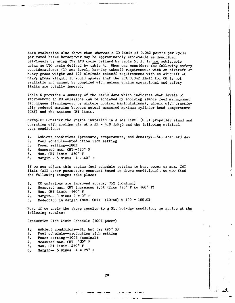
data evaluation also shows that whereas a CO limit of 0.042 pounds per cycleper rated brake horsepower may be approximately achievable as describedpreviously by using the LTO cycle defined by table 5; it is not achievableusing an LTO cycle defined by table 4. When one considers the following safetyconsiderations: (1) sea level, hot-day takeoff requirements with an aircraft atheavy gross weight and (2) altitude takeoff requirements with an aircraft atheavy gross weight, it would appear that the EPA 0.042 limit for CO is notrealistic and cannot be complied with unless engine operational and safetylimits are totally ignored.
Table 6 provides a summary of the NAFEC data which indicates what levels ofimprovement in CO emissions can be achieved by applying simple fuel managementtechniques (leaning-out by mixture control manipulations), albeit with drastic-ally reduced margins between actual measured maximum cylinder head temperature(CRT) and the maximum CHT limit.
Example: Consider the engine installed in a sea level (SL.) propeller stand andoperating with cooling air at a AP = 4.0 inH 20 and the following criticaltest conditions:
1. Ambient conditions (pressure, temperature, and density)-SL. stanard day2. Fuel schedule-production rich setting3. Power setting-l00%4. Measured max. CHT-4200 F5. Max. CHT limit-4600 F6. Margin- 5 minus 4 -40 F
If we now adjust this engine fuel schedule setting to best power or max. GHTlimit (all other parameters constant based on above conditions), we now findthe following changes take place:
1. CO emissions are improved approx. 75% (nominal)2. Measured max. (T increases 9.5% (from 4200 F to 4600 F)3. Max. CRT limit-4600 F4. Margin- 3 minus 2 = 00 F5. Reduction in margin (max. CHT)--(40t40) x 100 = 100.0%
Now, if we apply the above results to a SL. hot-day condition, we arrive at the
following results:
Production Rich Limit Schedule (100% power)
1. Ambient conditions-SL. hot day (950 F)2. Fuel schedule-production rich setting3. Power setting-100% (nominal)4. Measured max. CHT- 4 35 * F5. Max. CHT limit-4600 F6. Margin- 5 minus 4 - 25 F
28
1 144 0%
-41-0 00 0
0
z
I x I e n I.-0 41 J % 4tLn rl -4 0 0 0aC4 ~ 44e ~Er-l 0 4.cw
4-c o-44
04.4 04r ~gx 4 4 iE Or u 0 4 C
tn04
cn 0 Dr-o00r nr-.&JLn 4
1. -uiu V*0 0cl-c~4~4 . 2* , *IC'J C;- 4 0 -14 1- C40 0 C C )
P-44
En~ 0n LA0
C4~~~- Il-i D f)L
0 . . . .I t - o c r L )AC)0 00 00r 00 r
z -40 % f)C4-A ~ Mn :t m 0 4 -4 to0 a m~
C-4 0 4.4
U~~Z.0 00 .0L%0 ~ 4 C00 0 %,4P- 40 0- 'o en %O 0 14 4N u -1e n * 0 0 V ) . 0 C 4 '
Cfl~ ~ ~ ~ C 0n-m~ C0~4
000%0 0000000 ' 0 '0 '.0
0% 00ON 0% 00% 0
0000 C 0 00
cn00 0
> 44
0- 0 =- m. - 00 Ch
.4% 0% 9
0) C) -4 r. -
0 4440 .1.44 114X X.9*. 44~'~ 0 X,. -0 44~ 0
0- M.0 .0 4.00ecc -4 -4.4 ~
29
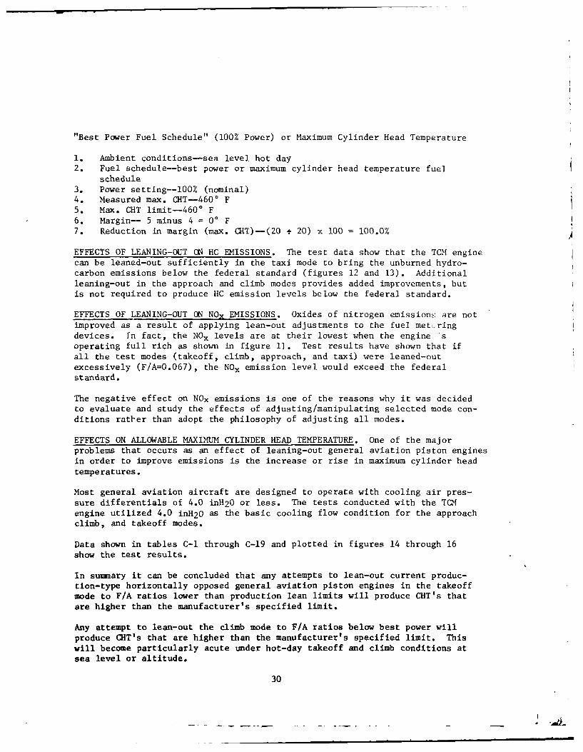
"Best Power Fuel Schedule" (100% Power) or Maximum Cylinder Head Temperature
1. Ambient conditions-sea level hot day2. Fuel schedule--best power or maximum cylinder head temperature fuel
schedule3. Power setting--100% (nominal)4. Measured max. CHT-4600 F5. Max. CHT limit--4600 F6. Margin-- 5 minus 4 = 0' F7. Reduction in margin (max. CHT)-(20 t 20) x 100 = 100.0% A
EFFECTS OF LEANING-OUT ON HC EMISSIONS. The test data show that the TCM enginecan be leaned-out sufficiently in the taxi mode to bring the unburned hydro-carbon emissions below the federal standard (figures 12 and 13). Additional
leaning-out in the approach and climb modes provides added improvements, butis not required to produce HC emission levels below the federal standard.
EFFECTS OF LEANING-OUT ON NOx EMISSIONS. Oxides of nitrogen emissions are notimproved as a result of applying lean-out adjustments to the fuel met, ringdevices. In fact, the NO, levels are at their lowest when the engine *soperating full rich as shown in figure 11. Test results have shown that ifall the test modes (takeoff, climb, approach, and taxi) were leaned-outexcessively (F/A=0.067), the NOx emission level would exceed the federalstandard.
The negative effect on NOx emissions is one of the reasons why it was decidedto evaluate and study the effects of adjusting/manipulating selected mode con-ditions rather than adopt the philosophy of adjusting all modes.
EFFECTS ON ALLOWABLE MAXIMUM CYLINDER HEAD TEMPERATURE. One of the majorproblems that occurs as an effect of leaning-out general aviation piston enginesin order to improve emissions is the increase or rise in maximum cylinder headtemperatures.
Most general aviation aircraft are designed to operate with cooling air pres-
sure differentials of 4.0 inH20 or less. The tests conducted with the TCMengine utilized 4.0 inH20 as the basic cooling flow condition for the approachclimb, and takeoff modes.
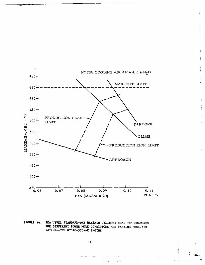
Data shown in tables C-1 through C-19 and plotted in figures 14 through 16show the test results.
In summary it can be concluded that any attempts to lean-out current produc-tion-type horizontally opposed general aviation piston engines in the takeoffmode to F/A ratios lower than production lean limits will produce CHT's thatare higher than the manufacturer's specified limit.
Any attempt to lean-out the climb mode to F/A ratios below best power willproduce CHT's that are higher than the manufacturer's specified limit. Thiswill become particularly acute under hot-day takeoff and climb conditions atsea level or altitude.
30
480NOTE: COOLING AIR A P =4. 0 inH2 O
M~AX. CHT LIMIT
440--
44420 /
0o 40 PRODUCTION LEAN--.&.
40 LIMIT /ITAKEOFF380-//
/ / CLIMB
360- /--PRODUCTION RICH LIMIT
APPROACH
0.06 0.07 0.08 0.09 0.10 0.11
F/A (MEASURED) 79-40-15
FIGURE 14. SEA LEVEL STANDARD-DAY MAXIMUM CYLINDER HEAD TEMPERATURESFOR DIFFERENT POWER MODE CONDITIONS AND VARYING FUE-AIRRATIOS--TCH GTS 10-520--K ENGINE
31
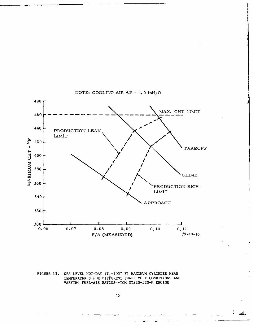
NOTE: COOLING AIR AP = 4. 0 inH 2 0
480
460--------------------------MAX. CHT LIMIT
440 PRODUCTION LEAN
LIMIT/o 420 1/
0 42/ TAK<EOFF
400 /
380 -38 / I/CLIMB
360 - PRODUCTION RICH
LIMIT340 -
APPROACH
320
300 1 I I0.06 0.07 0.08 0.09 0.10 0.11
F/A (MEASURED) 79-40-16
FIGURE 15. SEA LEVEL HOT-DAY (Ti-103* F) MAXIMUM CYLINDER HEADTEMPERATURES FOR DIFFERENT POWER MODE CONDITIONS ANDVARYING FUEL-AIR RATIOS--TCM GTSIO-520-K ENGINE
32
FUEL FLOWlb/h
PRODUCTION LEAN LIMIT
500 - A.CTLMT285
0
H480 -295
0 0
1310
0
380 -
(400 M CTLII PRODUCTION EAN LIMITFUEL FLOW
3801
440- FUE FLOW.-20
0 4Z 221
x 4400Z36
-0 F 9-4216
333
SUMMARY OF RESULTS
EXHAUST EMISSIONS.
1. The GTSIO-520-K engine does not meet the proposed EPA carbon monoxide andunburned hydrocarbon standards for 1979/80 under sea level standard dayconditions.
2. The GTSIO-520-K engine meets the EPA oxides of nitrogen standard for1979/80.
3. The engine fuel metering device could be adjusted on the test stand toreduce the current CO exhaust emission level, but not to levels required byproposed EPA standards when operating under the LTO cycle requirements.
4. The engine could be adjusted on the test stand to reduce the unburnedhydrocarbon exhaust emission level below the proposed EPA standard.
MAXIMUM CYLINDER HEAD TEMPERATURES.
1. Adjusting the fuel metering device in the takeoff and climb modes toconstant best power operation results in an increase in maximum CHT, whichwill exceed the engine specification limit on the test stand if cooling airL~P is limited to 4.0 inH-20 Or less.
2. No critical maximum CRT's result from leaning-out the approach and taximodes.
CRITICAL LANDING AND TAKEOFF CYCLE.
1. The most critical 1LO cycle is the cycle defined in this report as maxi-mum five-mode LTO cycle (table 4). Engine operation in accordance with themaximum five-mode LTO cycle in a sea level propeller test stand could not beadjusted to meet the proposed EPA Cf-emission standard for 1979/80 withoutexceeding engine maximum CRLT limits.
2. Engine operation in accordance with the minimum five-mode LTO cycle(table 5) could be adjusted to significantly improve the engine's emissionlevels.
CONCLUSIONS
The following conclusions are based on the testing accomplished with the TCMGTSIO0-520-K engine.
1. The single use of simple fuel management adjustments (altering of fuelschedule) do not allow safe reduction of exhaust emissions of the test engine,the TCM GTSIO-520-K. In conjunction with other data, references 12, 13, 14,15, and 16, this appears to be a valid general conclusion for typical light-aircraft piston engines.
34
2. The test data indicate that fuel management adjustments must be combinedwith engine/nacelle cooling modifications before safe and optimum low-emissionaircraft/engine combinations can be achieved.
3. The EPA CO limit of 0.042 lb/cycle/rated BHP is not achievable when take-off and climb requirements are impacted by aircraft heavy gross weight and theneed to pay close attention to CRT limitations,
4. Based on an assessment of the maximum five-mode LTO cycle (table 4) testdata, it is concluded that the following standard changes should be made tothe proposed EPA emission standards:
Proposed EPA Std.For 1979/80 Proposed Change to the 1979/80 Std.(lb/cycle/rated BHP) (lb/cycle/rated BHP)
CO Standard 0.042 0.075HC Standard 0.0019 0.0025NOx Standard 0.0015 0.0015
5. To avoid CHT problems in the takeoff mode (100-percent power), it isadvisable not to adjust the fuel metering device. Engine operation in thismode should continue to be accomplished within current production rich/leanlimits.
35
REFERENCES
1. Control of Air Pollution from Aircraft Engines, Environmental ProtectionAgency, Federal Register, Volume 38, No. 136, Part II, July 17, 1973.
2. Flow of Fluids Through Valves, Fittings, and Pipe, Crane IndustrialProducts Group, Technical Paper No. 410, 1957.
3. Salmon, R. F. and Imbrogno, S., Measurement and Testing ProblemsExperienced During FAA's Emission Testing of General Aviation Piston Engines,Aircraft Piston Engine Exhaust Emissions Symposium, Lewis Research Center,Cleveland, Ohio, September 14-15, 1976.
4. Liston, J., Power Plants for Aircraft, McGraw-Hill Book Company, Inc.,New York, 1953.
5. Obert, E. F., Internal Combustion Engines and Air Pollution, IntexLEducational Publishers, New York, 1973.
6. D'Alleva, B. A., Procedure and Charts for Estimating Exhaust Gas Quantities
and Compositions, General Motors Corp., Research Laboratories, GMR-372,May 15, 1960.
7. Graf, Gleeson, and Paul, Interpretation of Exhaust Gas Analyses,Engineering Experiment Station, Oregon State Agricultural College, BulletinSeries No. 4, 1934.
8. Guide to Aviation Products, Humble Oil and Refining Company, 1969.
9. NAPTC Fuel Sample Analysis - 100/130 Octane AviaLion Gasoline, 1976.
10. G.E. Aircraft Propulsion Data Book, General Electric, 1957.
11. Aeronautical Vest-Pocket Handbook, Pratt and Whitney Aircraft, 1957.
12. Becker, E. E., Exhaust Emissions Characteristics for a General AviationLight-Aircraft Avco Lycoming IO-360-BlBD Piston Engine, DOT/FAA/NAFEC,Report No. FAA-RD-78-129, 1978.
13. Recker, E. E., Exhaust Emissions Characteristics for a General AviationLight-Aircraft Avco Lycoming IO-360-AlB6D Piston Engine, DOT/FAA/NAFEC,Report No. FAA-RD-78-142, 1978.
14. Becker, E. E., Exhaust Emissions Characteristics for a General AviationLight-Aircraft TCM TSIO-360-C Piston Engine, DOT/FAA/NAFEC, Report No. FAA-RD-79-14, June 1979.
36
.i
15. Becker, E. E., Exhaust Emissions Characteristics for a General AviationLight-Aircraft TCM 6-285-B (TIARA) Piston Engine, DOT/FAA/NAFEC, ReportNo. FAA-RD-79-67, 1979.
16. Becker, E. E., Exhaust Emissions Characteristics for a General AviationLight-Aircraft Avco Lycoming TIO-540-J2BD Piston Engine, DOT/FAA/NAFEC,Report No. FAA-RD-79-68, 1979.
17. Stuckas, K. J., Exhaust Emissions Characteristics of Five AircraftPiston Engines, Teledyne Continental Motors, Aircraft Products Division,Mobile, Alabama, Report No. FAA-RD-78-80, 1979.
37
APPENDIX A
FUEL SAMPLE ANALYSIS
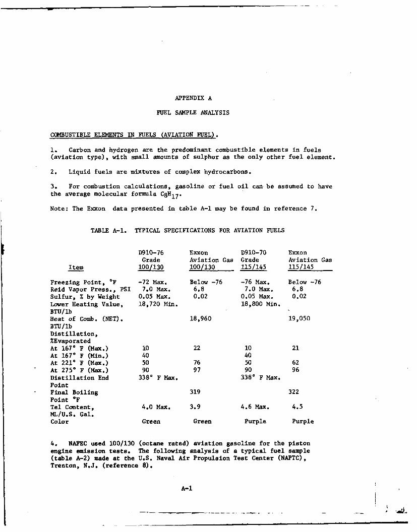
COMBUSTIBLE ELEMENTS IN FUELS (AVIATION FUEL).
1. Carbon and hydrogen are the predominant combustible elements in fuels(aviation type), with small amounts of sulphur as the only other fuel element.
2. Liquid fuels are mixtures of complex hydrocarbons.
3. For combustion calculations, gasoline or fuel oil can. be assumed to havethe average molecular formula C8H17.
Note: The Exxon data presented in table A-1 may be found in reference 7.
TABLE A-1. TYPICAL SPECIFICATIONS FOR AVIATION FUELS
D910-76 Exxon D910-70 ExxonGrade Aviation Gas Grade Aviation Gas
Item 100/ 130 100/130 115/145 115/145
Freezing Point, *F -72 Max. Below -76 -76 Max. Below -76Reid Vapor Press., PSI 7.0 Max. 6.8 7.0 Max. 6.8Sulfur, % by Weight 0.05 Max. 0.02 0.05 Max. 0.02Lower Heating Value, 18,720 Min. 18,800 Min.BTU/lbHeat of Comb. (NET). 18,960 19,050BTU/lbDistillation,%EvaporatedAt 1670 F (Max.) 10 22 10 21At 1670 F (Min.) 40 40At 2210 F (Max.) 50 76 50 62
* At 2750F (Max.) 90 97 90 96Distillation End 3380 F Max. 3380 F Max.Point
* Final Boiling 319 322Point *FTel Content, 4.0 Max. 3.9 4.6 Max. 4.5ML/U.S. Gal.Color Green Green Purple Purple
4. NAPEC used 100/130 (octane rated) aviation gasoline for the pistonengine emission tests. The following analysis of a typical fuel sample(table A-2) made at the U.S. Naval Air Propulsion Test Center (NAPTC),Trenton, N.J. (reference 8).
A-1
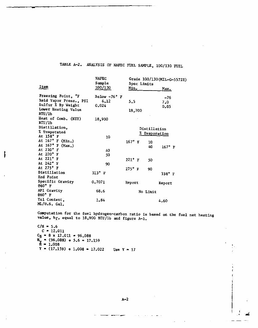
TABLE A-2. ANALYSIS OF NAFEC FUEL SAMPLE, 100/130 FUEL
NAFEC Grade 100/130(MIL-G-5572E)Sample Spec Limits
Item 100/130 Min. Max.
Freezing Point, *F Below -76* F -76Reid Vapor Press., PSI 6.12 5.5 7.0Sulfur % By Weight 0.024 0.05Lower Heating Value 18,700BTU/IbHeat of Comb. (NET) 18,900BTU/lbDistillation, Distillation% Evaporated % EvaporationAt 1580 F 10At 1670 F (Min.) 1670 F 10At 1670 F (Max.) 40 1670 FAt 2100 F 40At 220 ° F 50At 2210 F 221* F 50At 2420 F 90At 2750 F 2750 F 90Distillation 3130 F 3380 FEnd PointSpecific Gravity 0.7071 Report Report@600 FAPI Gravity 68.6 No Limit@600 FTel Content, 1.84 4.60ML/U.S. Gal.
Computation for the fuel hydrogen-carbon ratio is based on the fuel net heatingvalue, hf, equal to 18,900 BTU/lb and figure A-1.
C/H - 5.6C - 12.011
C8 - 8 x 12.011 - 96.088' " (96.088) + 5.6 - 17.159-1.008
Y - (17.159) t 1.008 - 17.022 Use Y - 17
A-2
APPENDIX B
COMPOSITION OF AIR (GENERAL. PROPERTIES)
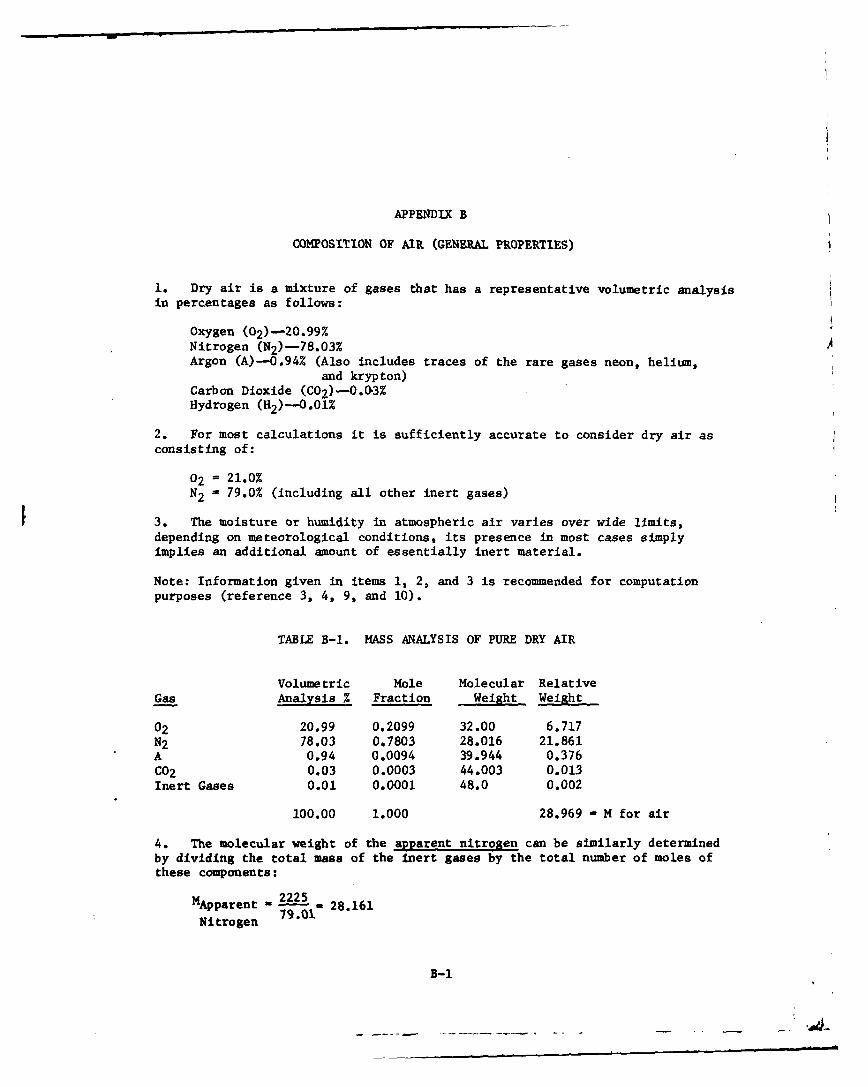
1. Dry air is a mixture of gases that has a representative volumetric analysisin percentages as follows:
Oxygen (02)-20.99%Nitrogen (N2)-78.03%Argon (A)-0.94% (Also includes traces of the rare gases neon, helium,
and krypton)Carbon Dioxide (C0 2 )-0.03%Hydrogen (M2 -O0l%
2. For most calculations it is sufficiently accurate to consider dry air asconsisting of:
02 21.0%N2 -79.0% (including all other inert gases)
3. The moisture or humidity in atmospheric air varies over wide limits,depending on meteorological conditions, its presence in most cases simplyimplies an additional amount of essentially inert material.
Note: Information given in items 1, 2, and 3 is recommended for computationpurposes (reference 3, 4, 9, and 10).
TABLE B-1. MASS ANALYSIS OF PURE DRY AIR
Volumetric Mole Molecular RelativeGas Analysis Z Fraction Weight Weight
02 20.99 0.2099 32.00 6.717N2 78.03 0.7803 28.016 21.861A 0.94 0.0094 39.944 0.376C02 0.03 0.0003 44.003 0.013Inert Gases 0.01 0.0001 48.0 0.002
100.00 1.000 28.969 - M for air
4. The molecular weight of the apparent nitrogen can be similarly determinedby dividing the total mass of the inert gases by the total number of moles ofthese components:
Mp~pparent - 222 28.161
Nitrogen 79.01
B-1
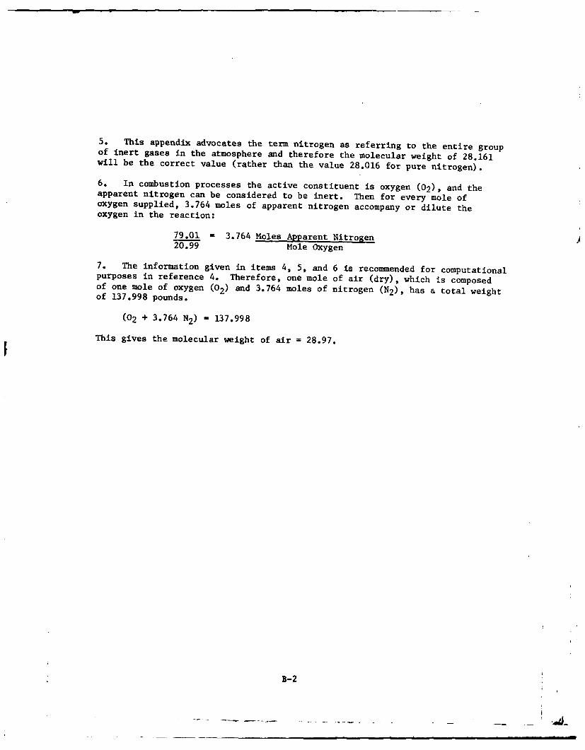
5. This appendix advocates the term nitrogen as referring to the entire groupof inert gases in the atmosphere and therefore the molecular weight of 28.161will be the correct value (rather than the value 28.016 for pure nitrogen).
6. In combustion processes the active constituent is oxygen (02), and theapparent nitrogen can be considered to be inert. Then for every mole ofoxygen supplied, 3.764 moles of apparent nitrogen accompany or dilute theoxygen in the reaction:
79.01 =3.764 Moles Apparent Nitrogen20.99 Mole Oxygen
7. The information given in items 4, 5, and 6 is recommended for computationalpurposes in reference 4. Therefore, one mole of air (dry), which is composedof one mole of oxygen (02) and 3.764 moles of nitrogen (N2), has a total weightof 137.998 pounds.
(02 + 3.764 N2) =137.998
This gives the molecular weight of air =28.97.
B-2
A
APPENDIX C
NAFEC TEST DATA AND WORKING PLOTS FOR ANALYSIS AND EVALUATIONTELEDYNE CONTINENTAL MOTORS (TCM) GTSIO-520-K ENGINE
.4
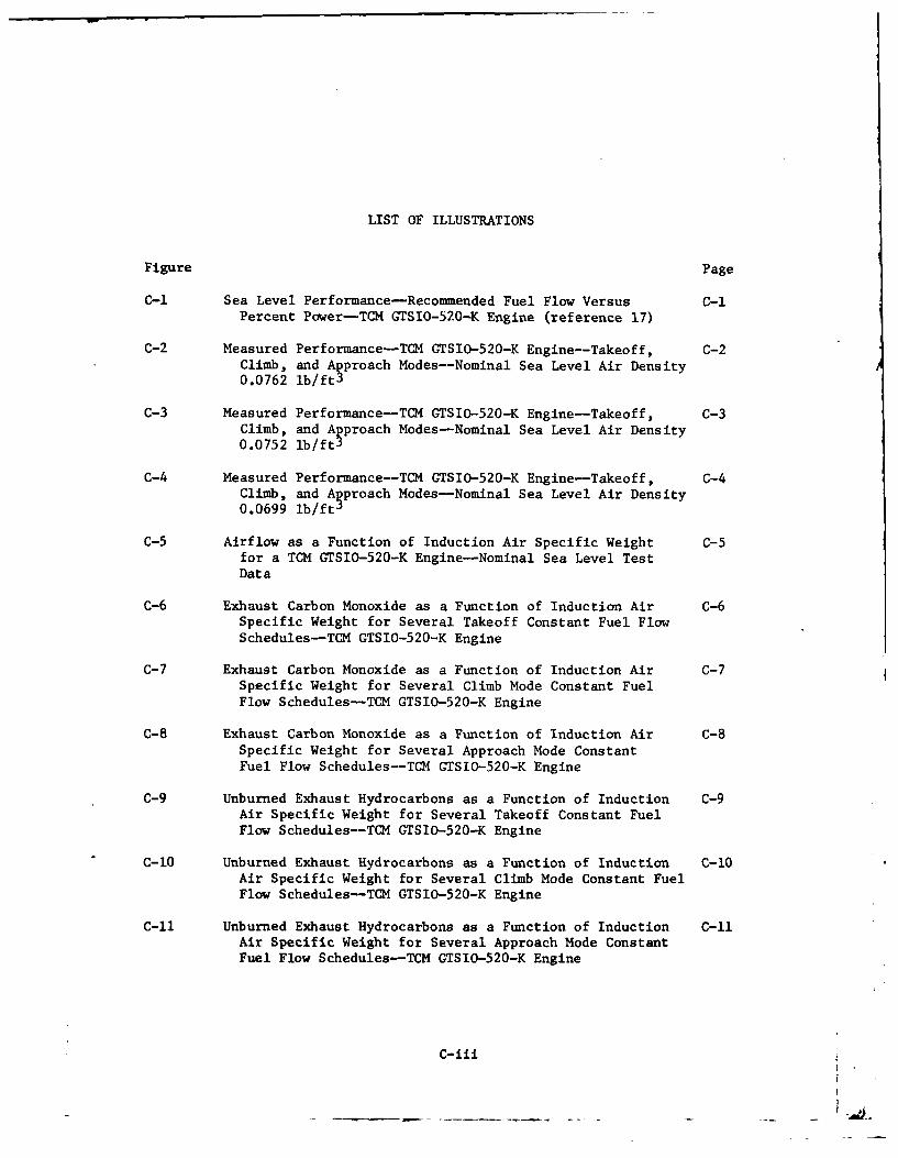
LIST OF ILLUSTRATIONS
Figure Page
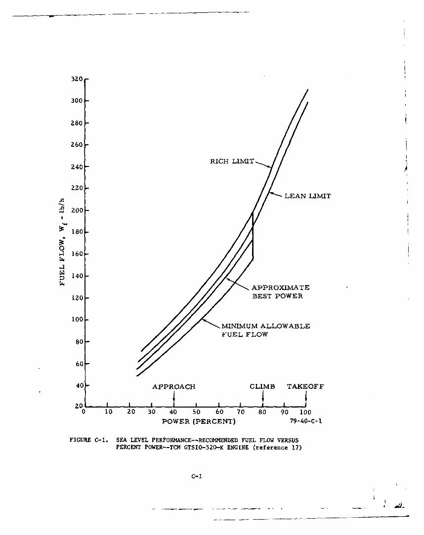
C-I Sea Level Performance-Recommended Fuel Flow Versus C-iPercent Power-TCM GTSIO-520-K Engine (reference 17)
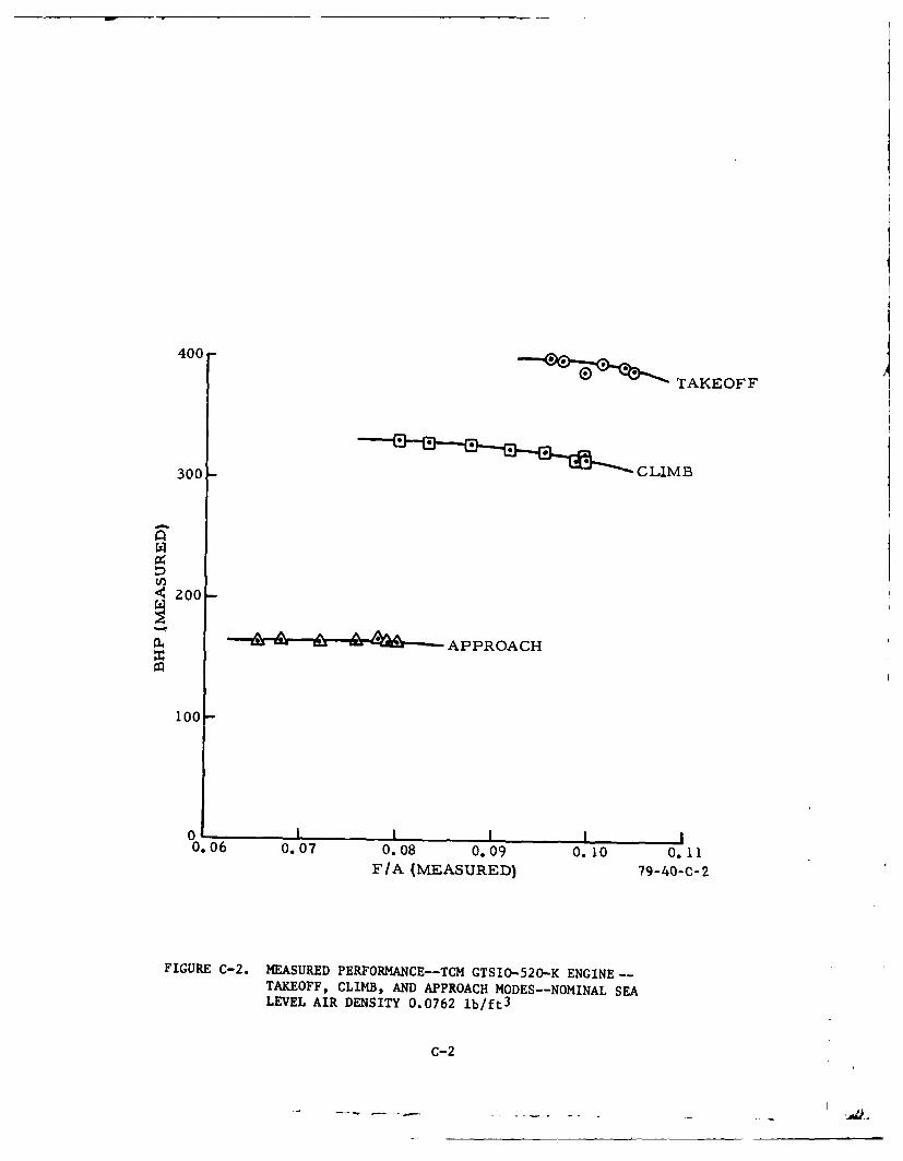
C-2 Measured Performance-TCM GTSIO-520-K Engine--Takeoff, C-2Climb, and Approach Modes--Nominal Sea Level Air Density0.0762 lb/ft3
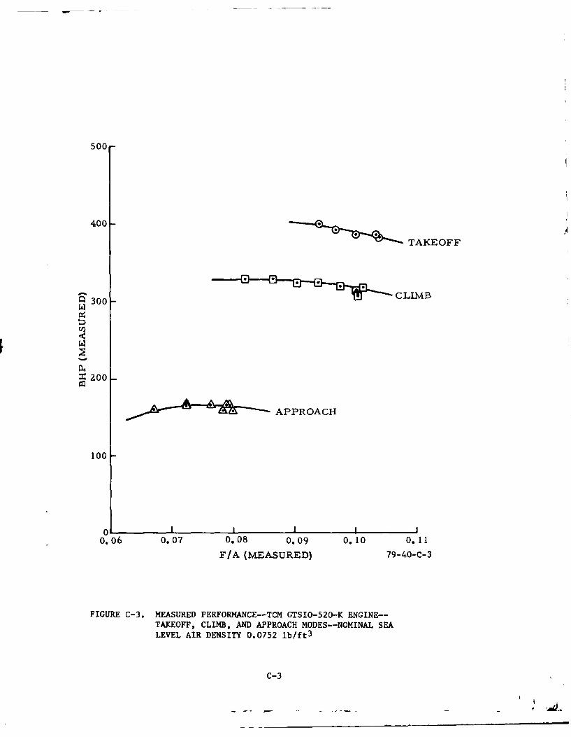
C-3 Measured Performance-TCM GTSIO-520-K Engine-Takeoff, C-3Climb, and Approach Modes-Nominal Sea Level Air Density0.0752 lb/ftS
C-4 Measured Performance--TCM GTSIO-520-K Engine--Takeoff, C-4Climb, and Approach Modes-Nominal Sea Level Air Density0.0699 Ib/ftJ
C-5 Airflow as a Function of Induction Air Specific Weight C-5for a TCM GTSIO-520-K Engine-Nominal Sea Level TestData
C-6 Exhaust Carbon Monoxide as a Function of Induction Air C-6Specific Weight for Several Takeoff Constant Fuel FlowSchedules-TCM GTSIO-520-K Engine
C-7 Exhaust Carbon Monoxide as a Function of Induction Air C-7Specific Weight for Several Climb Mode Constant FuelFlow Schedules-TCM GTSIO-520-K Engine
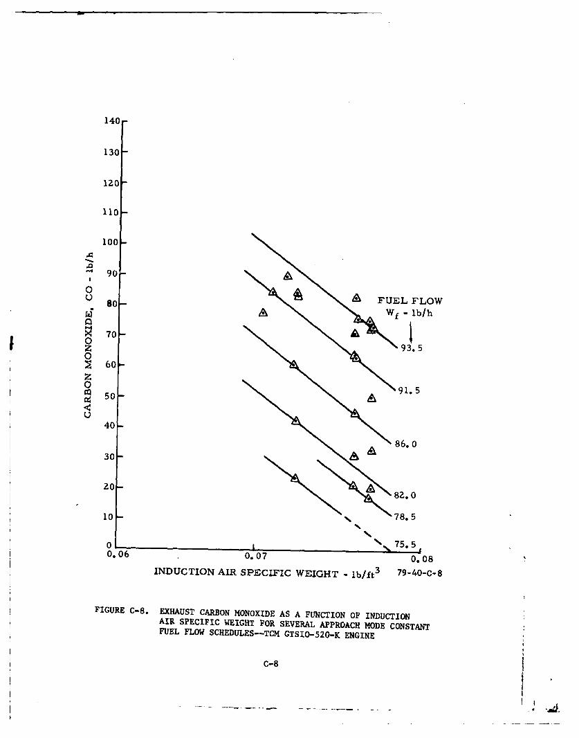
C-8 Exhaust Carbon Monoxide as a Function of Induction Air C-8Specific Weight for Several Approach Mode ConstantFuel Flow Schedules--TCM GTSIO-520-K Engine
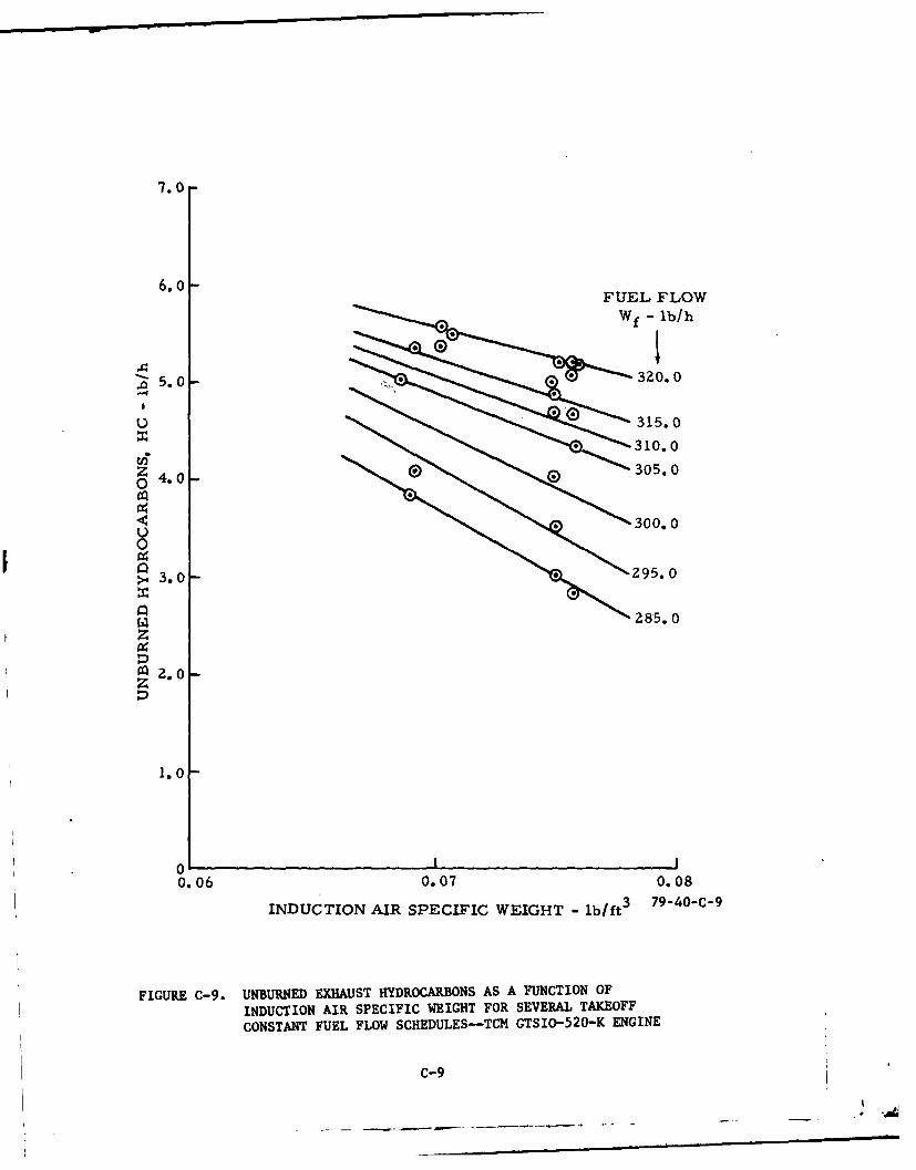
C-9 Unburned Exhaust Hydrocarbons as a Function of Induction C-9Air Specific Weight for Several Takeoff Constant FuelFlow Schedules--TCM GTSIO-520-K Engine
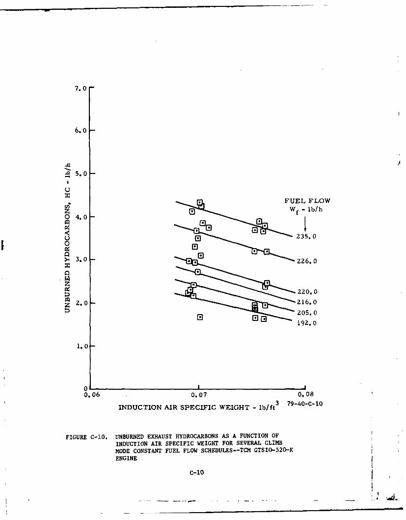
C-10 Unburned Exhaust Hydrocarbons as a Function of Induction C-1OAir Specific Weight for Several Climb Mode Constant FuelFlow Schedules--TCM GTSIO-520-K Engine
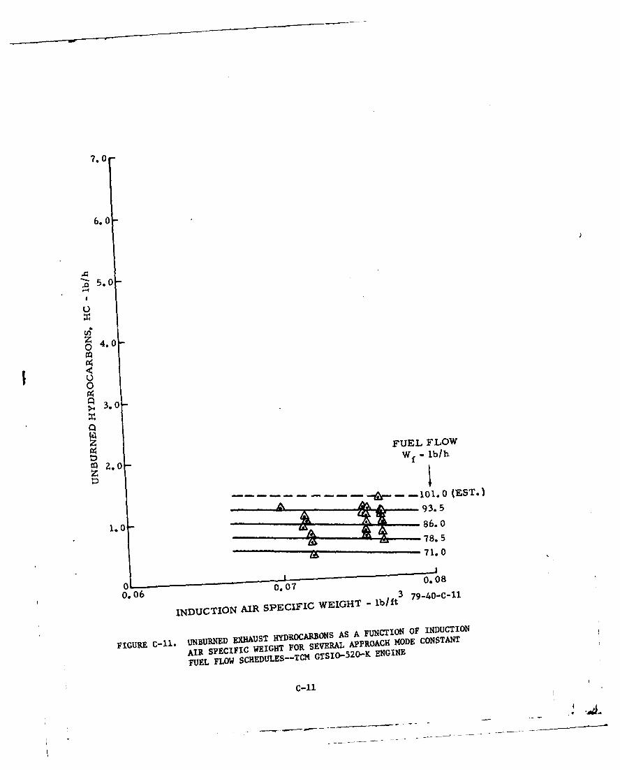
C-I Unburned Exhaust Hydrocarbons as a Function of Induction C-liAir Specific Weight for Several Approach Mode ConstantFuel Flow Schedules-TCM GTSIO-520-K Engine
C-iii
LIST OF ILLUSTRATIONS (Continued)
Figure Page
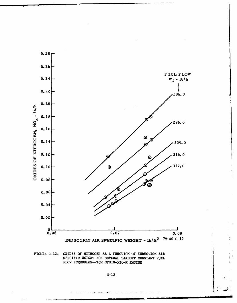
C-12 Oxides of Nitrogen as a Function of Induction Air C-12Specific Weight for Several Takeoff Constant Fuel FlowSchedules--TCM GTSIO-520-K Engine
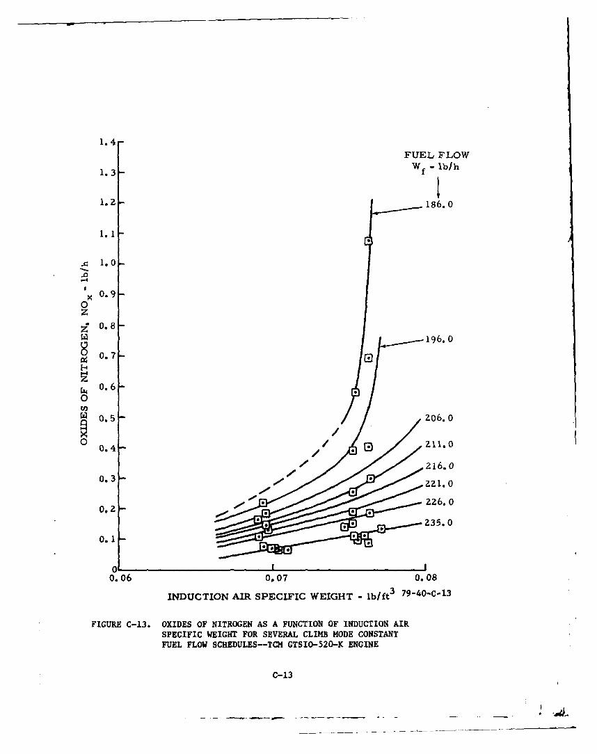
C-13 Oxides of Nitrogen as a Function of Induction Air C-13Specific Weight for Several Climb Mode Constant FuelFlow Schedules--TCM GTSIO-520-K Engine
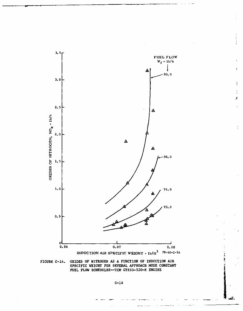
C-14 Oxides of Nitrogen as a Function of Induction Air C-14Specific Weight for Several Approach Mode Constant FuelFlow Schedules--TCM GTSIO-520-K Engine
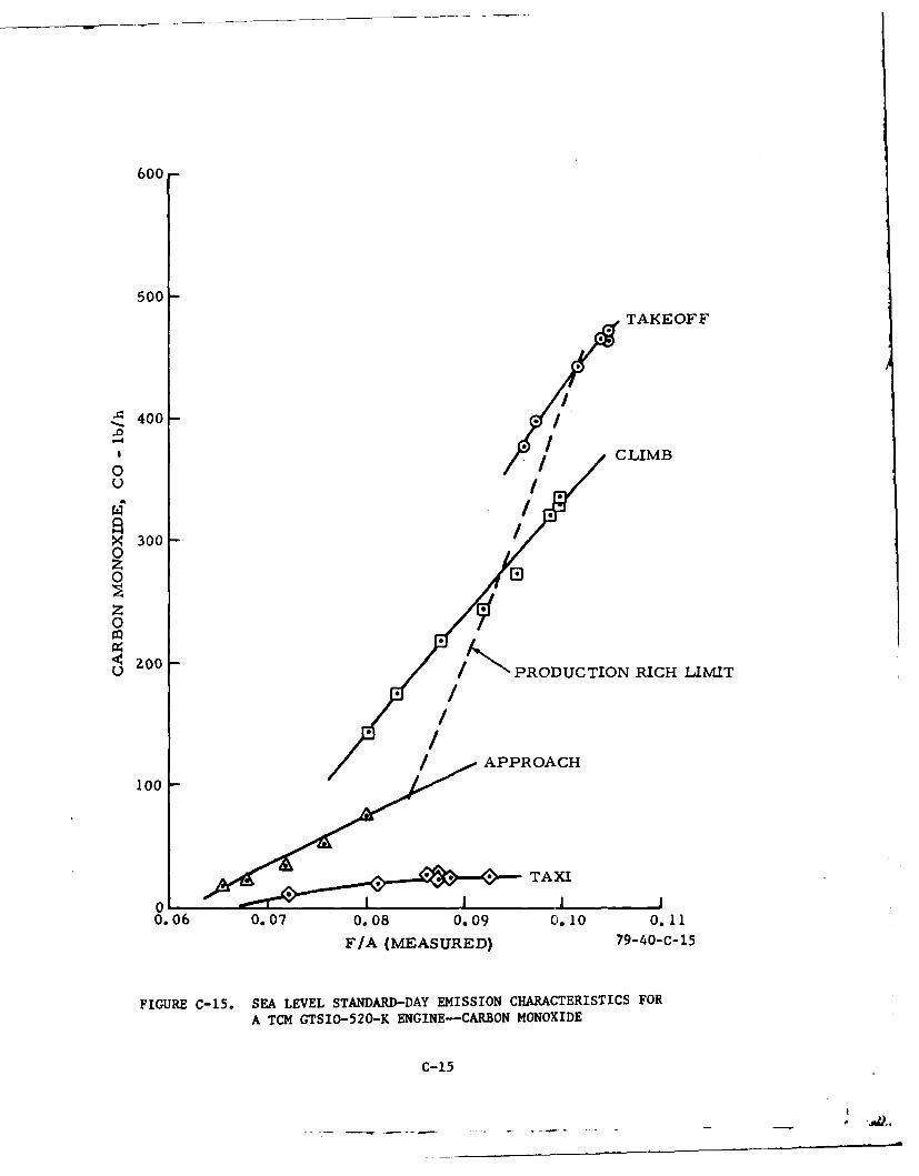
C-15 Sea Level Standard-Day Emission Characteristics for a C-15TCM GTSIO-520-K Engine--Carbon Monoxide
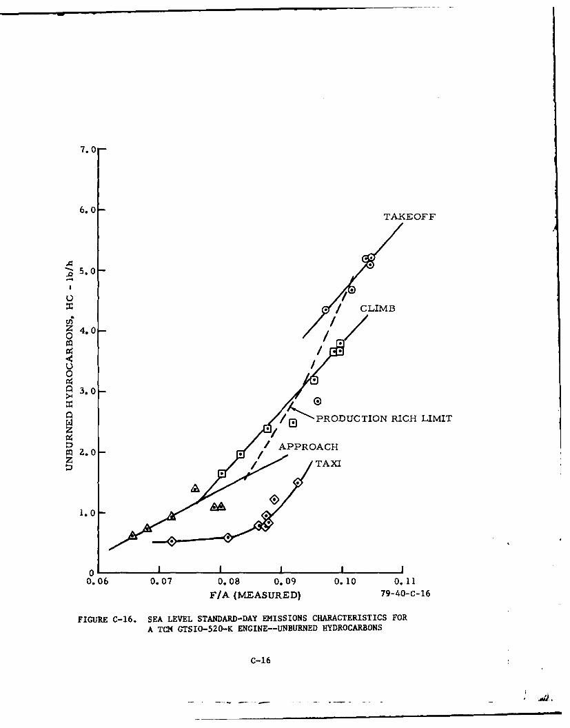
C-16 Sea Level Standard-Day Emissions Characteristics for a C-16TCM GTSIO-520-K Engine--Unburned Hydrocarbons
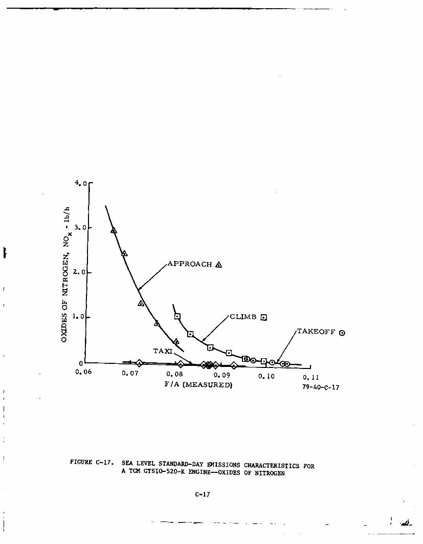
C-17 Sea Level Standard-Day Emissions Characteristics for a C-17TCM GTSIO-520-K Engine-Oxides of Nitrogen
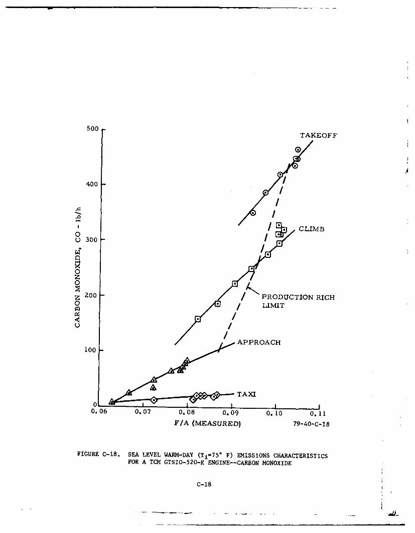
C-18 Sea Level Warm-Day (Ti=75* F) Emissions Characteristics C-18for a TOC GTSIO-520-K Engine--Carbon Monoxide
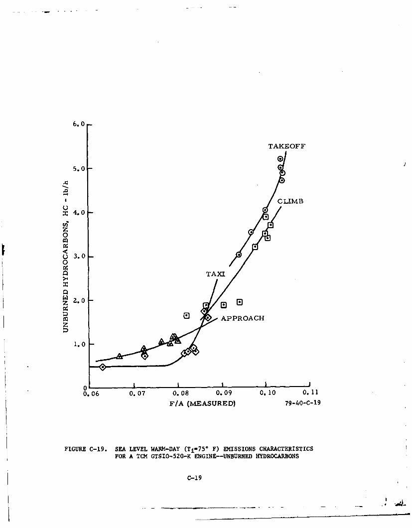
C-19 Sea Level Warm-Day (Ti=750 F) Emissions Characteristics C-19for a TCM GTSIO-520-K Engine-Unburned Hydrocarbons
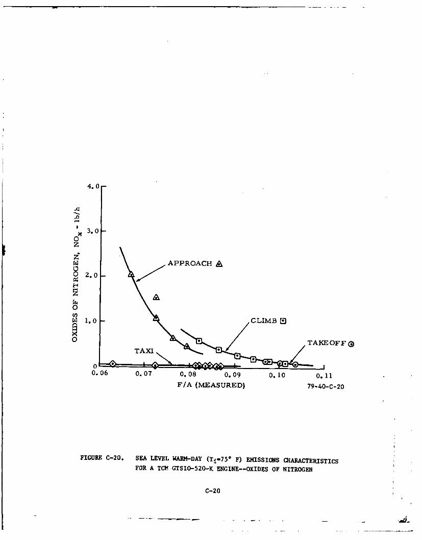
C-20 Sea Level Warm-Day (Ti=750 F) Emissions Characteristics for C-20a TCM GTSIO-520-K Engine--Oxides of Nitrogen
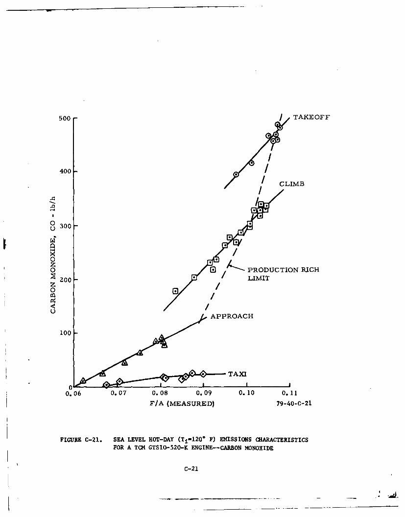
C-21 Sea Level Hot-Day (Ti=1200 F) Emissions Characteristics for C-21a TCMGTSIO-520-K Engine--Carbon Monoxide
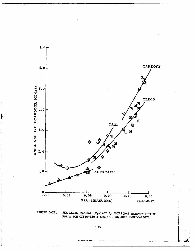
C-22 Sea Level Hot-Day (Ti=1200 F) Emissions Characteristics for C-22a TCM GTSIO-520-K Engine-Unburned Hydrocarbons
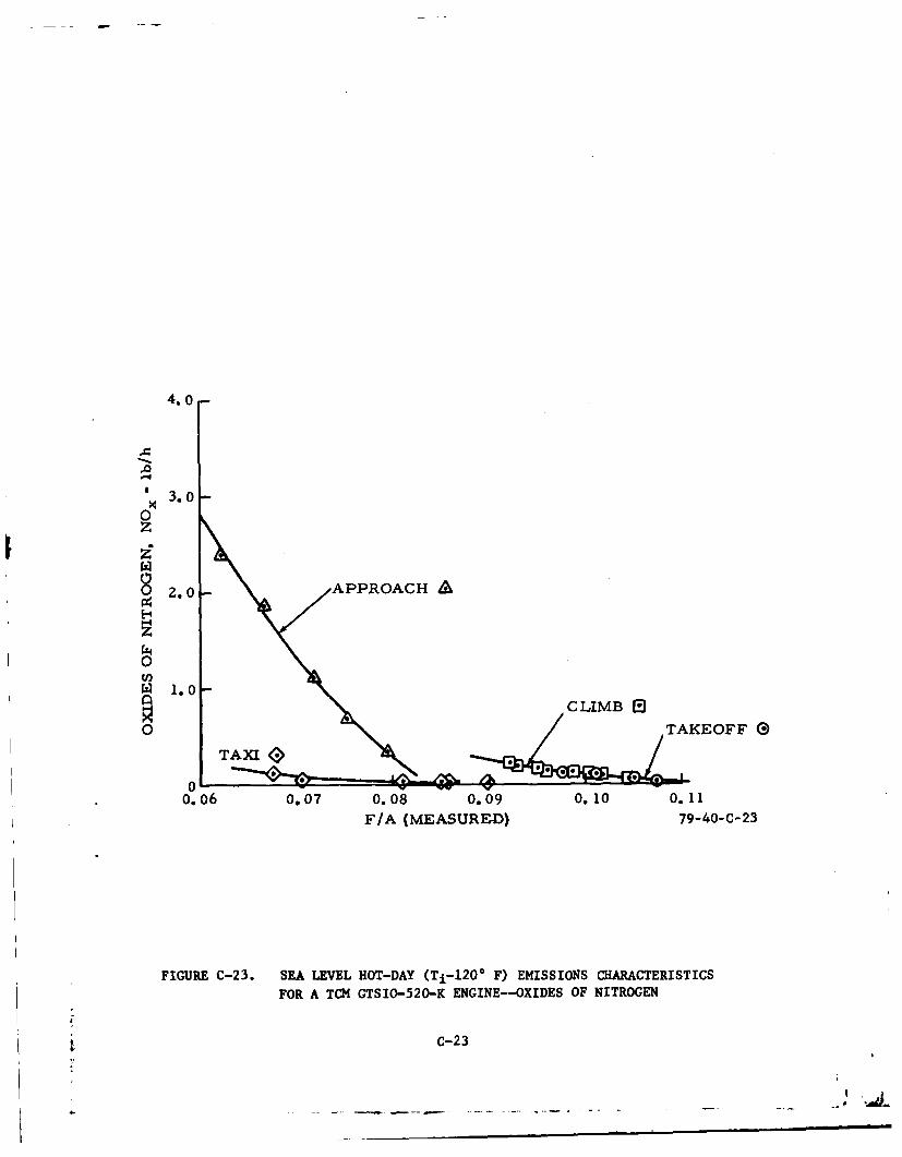
C-23 Sea Level Hot-Day (Ti-120° F) Emissions Characteristics for C-23a TCM GTSIO-520-K Engine--Oxides of Nitrogen
C-iv
320
300-
Z80 -
Z60 -
RICH LIMIT240 -
220 -LEAN LIMIT
zoo-
180
04 160-
D 140-/4 / APPROXIMATE
1z0- BEST POWER
100 -
MINIMUM ALLOWABLEFUEL FLOW
80-
60-
40- APPROACH CLIMB TAKEOFF
20 I f I I I I ! I0 10 20 30 40 50 60 70 80 90 100
POWER (PERCENT) 79-40-C-i
FIGURE C-i. SEA LEVEL PERFORMANCE--RECOMMENDED FUEL FLOW VERSUSPERCENT POWER--TCM GTSIO-520-K ENGINE (reference 17)
C-i
400-
TAKEOFF
300 - CLIMB
zoo
&I APPROACH
100-
00.06 0.07 0.08 0.09 0.10 0.11F/A (MEASURED) 79-40-C-2
FIGURE C-2. MEASURED PERFORMANCE--TCM GTSIO-520-K ENGINE--TAKEOFF, CLIMB, AND APPROACH MODES--NOMINAL SEALEVEL AIR DENSITY 0.0762 lb/ft3
C-2
500-
400
TAKEOFF
CLIMB
~ APPROACH
100
00.06 0.07 0.08 0.09 0.10 0.11
F/A (MEASURED) 79-40-C-3
FIGURE C-3. MEASURED PERFORMANCE-TCM GTSIO-520-K ENGINE--TAKEOFF, CLIMB, AND APPROACH MODES--NOMINAL SEALEVEL AIR DENSITY 0.0752 lb/ft 3
C-3
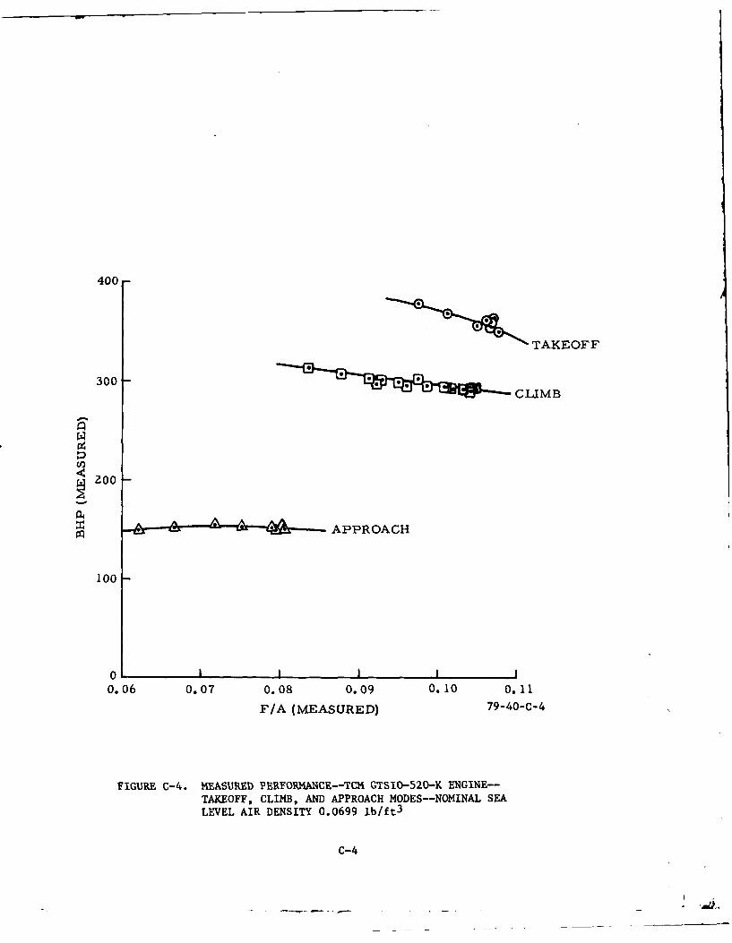
400-
TAKEOFF
300- CLIMB
200-
APPROACH
100 -
0 . i I I I I
0.06 0.07 0.08 0.09 0.10 0.11
F/A (MEASURED) 79-40-C-4
FIGURE C-4. MEASURED PERFORMA0CE--TCM GTSIO-520-K ENGINE--TAKEOFF, CLIMB, AND APPROACH MODES--NOMINAL SEALEVEL AIR DENSITY 0.0699 lb/ft
3
C-4
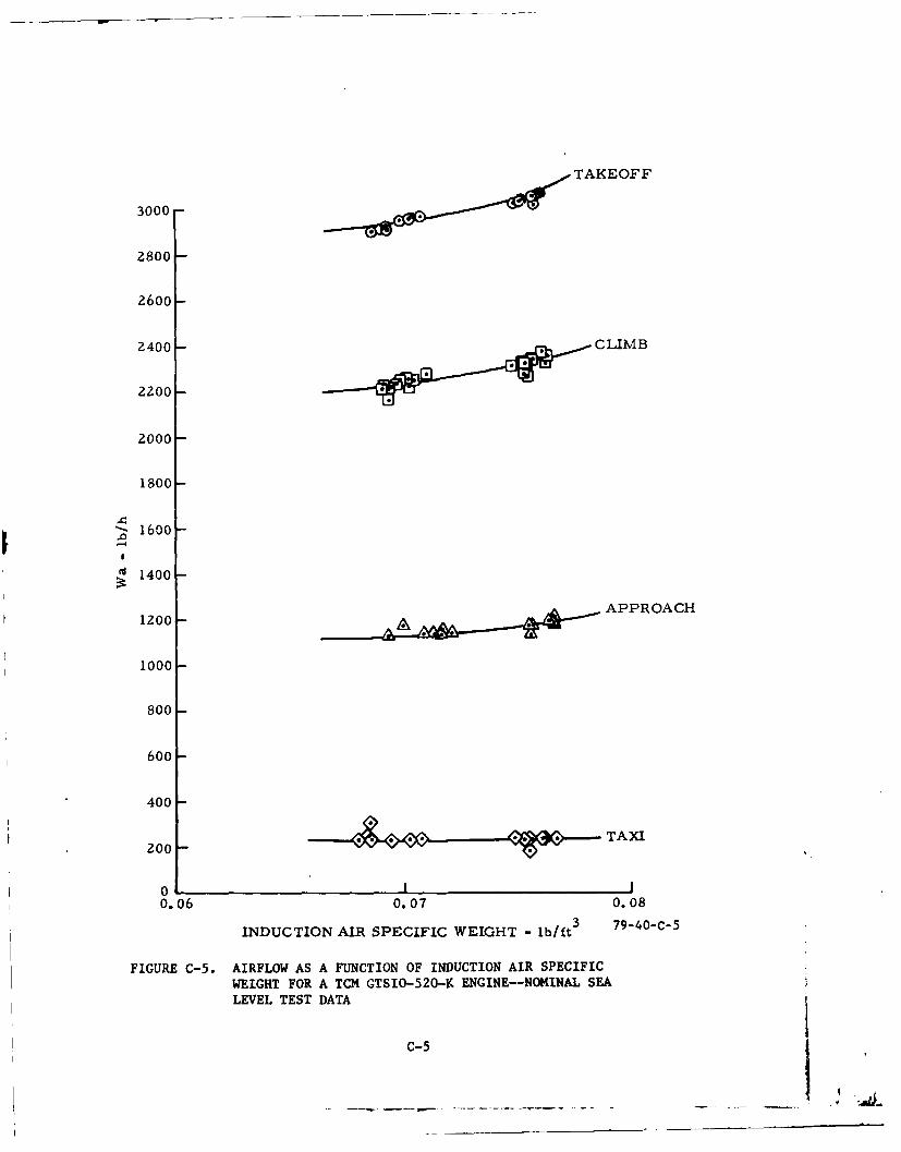
TAKEOFF
3000
2800
2600-
2400 * CLIMB
2200- 1
2000-
1800-
-1600
'~1400
APPROACH1200
1000
800
600
400
200 TA-
0 .I0.06 0.07 0.08
INDUCTION AIR SPECIFIC WEIGHT -lb/ft 3 79-40C-5
FIGURE C-5. AIRFLOW AS A FUNCTION OF INDUCTION AIR SPECIFICWEIGHT FOR A TCM GTSIO-520-K ENGINE--NOMINAL SEALEVEL TEST DATA
c-5
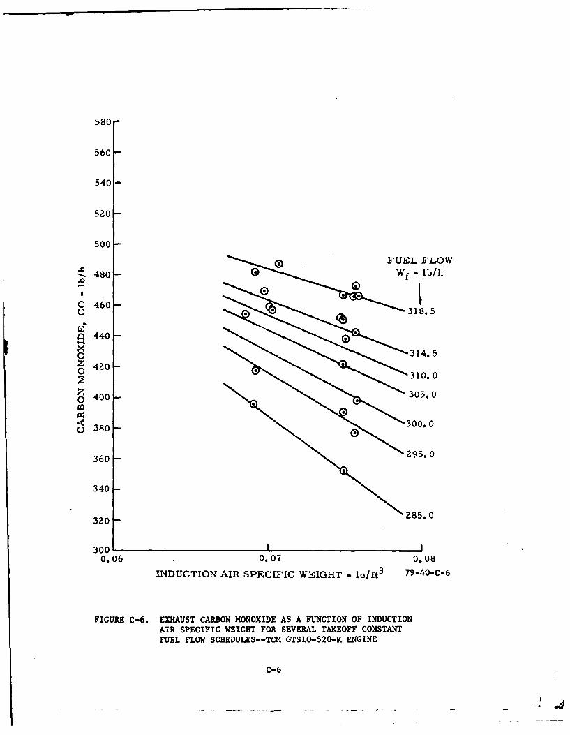
580-
560
540 -
520-
500
480- f l/
- G)o 460-
0z 440
o 400 -
0 380.
3 400 0.
320
300
0.06 0.07 0.08
INDUCTION AIR SPECIFIC WEIGHT - lb/ft 3 79-40-C-6
FIGURE C-6. EXHAUST CARBON MONOXIDE AS A FUNCTION OF INDUCTIONAIR SPECIFIC WEIGHT FOR SEVERAL TAKEOFF CONSTANTFUEL FLOW SCHEDULES--TCM GTSIO-520-K ENGINE
C-6
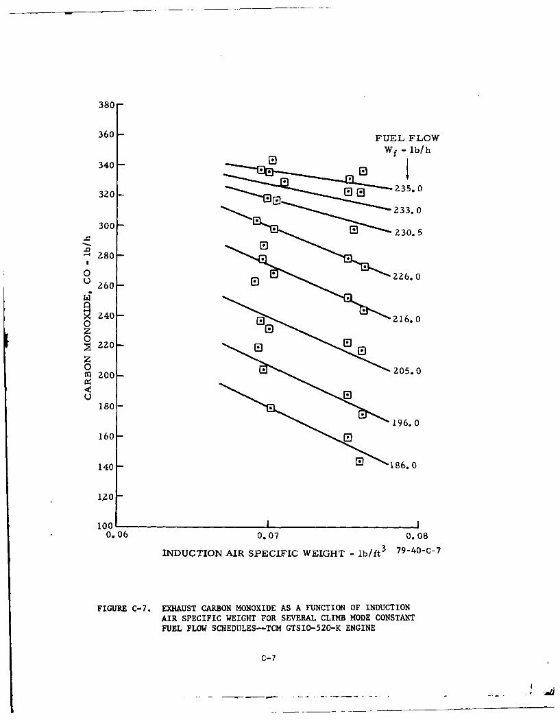
380
360 -FUEL FLOW
340 -W -lb/h
320- 00235.0
233. 0
30023.
226.
280-
260-
0 Z4 16. 0
zG0
g220-z0 205.0m 200-
u E180-
196. 0
160-E
140-G 18.
10010.06 0.07 0.08
INDUCTION AIR SPECIFIC WEIGHT - lb/ft 379-40-C-7
FIGURE C-7. EXHAUST CARBON MONOXIDE AS A FUNCTION OF INDUCTIONAIR SPECIFIC WEIGHT FOR SEVERAL CLIMB MODE CONSTANTFUEL FLOW SCHEDIULES--TCM GTSIO-520-K ENGINE
C-7
140
130-
120
110-
100-
90-
0
Q so-FUL LO80 W f lb/h
70-2 93.5
0
6O-
19 0-
z%
0 A 91.5
U!
40
86. 030-
20- 8-. 0
10- 78.5
0 %* 75. 50.06 0.07 o.08
INDUCTION AIR SPECIFIC WEIGHT - lb/ft3 79-40-C-8
FIGURE C-8. EXHAUST CARBON MONOXIDE AS A FUNCTION OF INDUCTIONAIR SPECIFIC WEIGHT FOR SEVERAL APPROACH MODE CONSTANTFUEL FLOW SCHEDULES--TCM GTSIO-520-K ENGINE
C-8
- - ~ ~ ---
7. 0
6.o- FUEL FLOW
5.0- 2.
u 315.0
z 305.0o4.0-
300.0
0
>-4 3.0-
m 285.0w
ze
1. 0
00.06 0.07 0.08
INDUCTION AIR SPECIFIC WEIGHT - lb/ft 3 79-40-C-9
FIGURE C-9. UNBURN4ED EXHAUST HYDROCARBONS AS A FUNCTION OFINDUCTION AIR SPECIFIC WEIGHT FOR SEVERAL TAKEOFFCONSTANT FUEL FLOW SCHEDULES--TCM GTSIO-520-K ENGINE
C-9
7.0
6.0-
5.0 -
.FUEL FLOW
z Wf - lb/h0 4.0
0 8 Z35.o0
0
3.0 .0 226. 0
's 220. 0
z2.0 216.0205.0
192.0
1.0
0 I__0.06 0.07 0.08
INDUCTION AIR SPECIFIC WEIGHT - lb/ft 3 79-40-C-10
FIGURE C-10. UNBURNED EXHAUST HYDROCARBONS AS A FUNCTION OFINDUCTION AIR SPECIFIC WEIGHT FOR SEVERAL CLIMBMODE CONSTANT FUEL FLOW SCHEDULES--TCM GTSIO-520-KENGINE
C-1O
7.0
6.0
n 5.0
o 4.0
0
3.0
zFUEL FLOW
w - lb/h
M~ 2.0f
.~---------- ---io1. o (EST.)
93.5
1.0 A 86.0
£6--- 78.571.0
0 0.07 0.08INDUCTION AIR SPECIFIC WEIGHT - lb/ft 79-40-C-11
FIGURE C-li. UNBURNED EAIAUST HYDROCARBONS AS A FUNCTION OF INDUCTION
AIR SPECIFIC WEIGHT FOR SEVERAL APPROACH MODE CONSTANT
FUEL FLOW SCHEDULES--TCM GTSIO-5
20-K ENGINE
C-11
0. 28 -
0.26
FUEL FLOW0. 24- Wf - lb/h
0.22 - 1
0.zo0-
0.18-o
0.12- 316.0
0co, 317.0f4 0.10-
0 0.08
0.06
0.04
0.02
0 I I0.06 0.07 0.08
INDUCTION AIR SPECIFIC WEIGHT - lb/ft3 79-40-C-12
FIGURE C-12. OXIDES OF NITROGEN AS A FUNCTION OF INDUCTION AIRSPECIFIC WEIGHT FOR SEVERAL TAKEOFF CONSTANT FUELFLOW SCHEDULES--TCM GTSIO-520-K ENGINE
C-12
• J ! - •. • i i i I I j
1.4-
FUEL FLOW
1.3- Wf - lb/h
1.) 1
S1.0
x 0.90z
0.8 196. 0
8. 0.7
wZ 0.6-0
0.5 - 206.0
0 0.4- 1.
0.3 110216.0
226. 0
0.2 22.
0. 1
0e
0.06 0.07 0.08
INDUCTION AIR SPECIFIC WEIGHT -lb/ft 379-40-C-13
FIGURE C-13.* OXIDES OF NITROGEN AS A FUNCTION OF INDUCTION AIRSPECIFIC WEIGHT FOR SEVERAL CLIMB MODE CONSTANTFUEL FLOW SCHEDULES--TCM GTSIO0-520-K ENGINE
C-13
3.5FUEL FLOW
Wf - lb/h
80.0
3.0
2. 5
.0
0
2.0
86.01.5-
0
~93. 0
0 I I0.06 0.07 0.08
INDUCTION AIR SPECIFIC WEIGHT - lb/ft 3 79-40-C-14
FIGURE C-14. OXIDES OF NITROGEN AS A FUNCTION OF INDUCTION AIRSPECIFIC WEIGHT FOR SEVERAL APPROACH MODE CONSTANTFUEL FLOW SCHEDULES--TCM GTSIO-520-K ENGINE
C-14
600 -
500
TAKEOFF
400 /-4 CLIMB
0u I
X 3000Z0
z0
o PRODUCTION RICH LIMITu/
00 APPROACH
100
010.06 0.07 0.08 0.09 0.10 0.11
F/A (MEASURED) 79-40-C-15
FIGURE C-15. SEA LEVEL STANDARD-DAY EMISSION CHARACTERISTICS FORA TCM GTSIO-520-K ENGINE--CARBON MONOXIDE
C-15
7.0-
6.0- TAKEOFF
5.0-.- 4
u
o 4 . 0 - /0m
0/U /
3.0-
w/m PRODUCTION RICH LIMIT
/ APPROACHm . 0-
t) TAXI
1.0-
0 , I I 1 I0.06 0.07 0.08 0.09 0.10 0.11
F/A (MEASURED) 79-40-C-16
FIGURE C-16. SEA LEVEL STANDARD-DAY EMISSIONS CHARACTERISTICS FORA TCM GTSIO-520-K ENGINE--UNBURNED HYDROCARBONS
C-16
- - - .- -.. I e iII
.-
3.0-ox
0z
APPROACH &
0. &
c 1.0 CLIMB 9TAKEOFF 0)
0
TAXI
0.06 0.07 0.08 0.09 0.10 0.11F/A (MEASURED) 79-40-C-17
FIGURE C-17. SEA LEVEL STANDARD-DAY EMISSIONS CHARACTERISTICS FORA TCM GTSIO-520-K ENGINE--OXIDES OF NITROGEN
C-17
- - -
500
TAKEOFF
0
400 /
;:0./I
' CLIMB0U 300
z0
z 200 PRODUCTION RICH0 LIMIT
APPROACH100
~TAXI
00.06 0.07 0.08 0.09 0.10 0.11
F/A (MEASURED) 79-40-c-18
FIGURE C-18. SEA LEVEL WARM-DAY (Ti=750 F) EMISSIONS CHARACTERISTICSFOR A TCM GTSIO-520-K ENGINE--CARBON MONOXIDE
C-18
, * , , . , - .. ..
6.0-
TAKEOFF0
5.0 -
,-9
CLIMB
4.0
z0m
U 3.00
TAXI
z.0 S
8 *- APPROACHz
1.0 0
0 i0.06 0.07 0.08 0.09 0.10 0.11
F/A (MEASURED) 79-40-C-19
FIGURE C-19. SEA LEVEL WARM-DAY (Tja-75 0 F) EMISSIONS CHARACTERISTICSFOR A TCM GTSIO-520-K ENGINE--UNBURNED HYDROCARBONS
C-19
c-i 9
4. 0 -
4.0-
3.0
z2
APPROACH ,€
82.0
0W 1.0 CLIMB 8
0 TAKEOFF CDTAXI
0.06 0.07 0.08 0.09 0.10 0.11F/A (MEASURED) 79-40-C-20
FIGURE C-20. SEA LEVEL WARM-DAY (Ti-750 F) EMISSIONS CHARACTERISTICSFOR A TC- GTSIO-520-K ENGINE--OXIDES OF NITROGEN
C-20
500 I TAKEOFF
400 /
CLIMB
/0
0
o 300
z /O0'~ PRODUCTION RICHl 200- LIMIT
,4,A P P R O A C H
I 100-
0TA Ml
0.06 0.07 0.08 0009 0.10 0.11
F/A (MEASURED) 79-40-C-21
FIGURE C-21. SEA LEVEL HOT-DAY (Ti-1200 F) EMISSIONS CHARACTERISTICSFOR A TCM GTSIO-520-K ENGINE--CARBON MONOXIDE
c-21
0.060.07 0.080.09 0.100.1
7. 0-
6.0 TAKEOFF
5.0 -
CLIMB
E8z0o4.0
0TAXI S
> 3.0
? .0
.<i>
1.0- APPROACH
00.06 0.07 0.08 0.09 0.10 0.11
F/A (ME~ASUJRED) 79-40-C-22
FIGURE C-22. SEA LEVEL HiOT-DAY (Ti-120- F) ENISSIONS CHARACTERISTICSFOR A TCM GTSIO-520-K ENGINE--UNBURNED HYDROCARBONS
C-22
4.0
,-4
3.0
0z
8 2.0 AAPPROACH
0
L 1.0N/~ CLIMB
O TAKEOFF GTA~l
0.06 0.07 0. 08 0.09 0.10 0.11F/A (MEASURED) 79-40-C-23
FIGURE C-23. SEA LEVEL HOT-DAY (Ti-120- F) EMISSIONS CHARACTERISTICSFOR A TCM GTSIO-520-K ENGINE--OXIDES OF NITROGEN
C-23
-4- , Ctu% -c*I * UN - - CO - .4 1 N n 44' 4 40., '0 en *- r- 00 Os' -40 C. n*4r 4 ... r- 0c M 0
I K4 00 0 - 0 4 00 r- 0 u- e C1C4 0 . .C
co3 en' 0 0 0 000
u- 01 -tU) 1 Jr- Un0 0 4 U40 OCJr " 0' %D I' r- C. WL M '0 Ui
0z - r -1i0 *r- fn Ln r*C)C' nC4V 4 . . .Lo 4tn 00 0 C4C'I 0 0%000 -4 0%%0 0-4 f-r-J
936 ~ ~ M0n140 -C
1-4
0zI-L) -.0 '0 0 X oC40"0 n I0 r -0ui0% 00 00rI - I
-4 - Dr n 0e nV 0c I'IC ' .U 'T C4 -* ~ - 4 " Jm-4 n n' 44 U4 M C* 4 C-4 *f n .
-I 00 M . e40CM4-4 C-4 IAn0 0I Cz0 0 Clo '
'-a
44-,I 40" t ,r 1 10I 1 D0 C40Jlr 400 nI
E4
w 41
1* 00 0c0('JC 0 C- t) ,4'0. . 0 NC'J4 - . f C,K' cn -4 C; C; 0 0
00-
0
0L0
E-*-
fboUM 0) .4W-E4 A.ifZ 411
P I. 124 Woo 44*4 W &
-. X. 1 90 0 0 1.
$4 14 W0 W ."I s 4d 141 0) 0
-4 -4 4 .A'0 &. 000% 0-3C 44 A0 0 N) at I'0 0) 0) 00--------- 4 .4 NC N N N N N4 N4 N0 V
Cc2
'0 '4 (n r m CI*nenNU -I .. 0~ ON-00 0 c000 ; 0 0- -4 04 00 00' 0 ~ 4 W$ m-
m 4 0 0(4C40 0 -0 0,0 r 004-
'fn M 00- 00 000
M ~ t o ~ 0 0n 0 N e - 0 c "- 4 UCO.- 0 -0 0 a 0 CN' J . - 4 0
130 0 -04 4
en 4) -00 -- 0 ( -u *4 N r- D -*O,0NNx cn -4 Cfco4~ c- C' ; C4Cc -; Cc 0'1-co-E-
x 0)en0
144 E-4% % 0 - 0 -U(
00
U 4.400 - 0 -- - "
In 0-40 0- - 0- c,
.0 0 0U0
-414-m u 4
A .464 A4A®0~-4 -m
a a 4c ; 9a :c 4c 9a ;c
~ 004 .. ~. 04 -25
1-4 0%s~r LA~ *l .' O0. In %0U' -4 -4.-40,ML 4L C - n. a f--4 %a VI -0 4 U% 0 %0
I, -4 m 00 0- (n m N r- . 0U .CV) J-m400% w 0 C; *4- CS! 0 0000 L% C4 40 .
E4C1 0 0
0M 0 m 4M 0 c N 0 .4 Cl *440h
a% .0 -' C4 C- 0'0000ML - D C D .
0 ~ ~ r 0 momNWMJ0
'4 44 % N- 0 nC -e *C 0'Ch 0 *-4 n 4C *4 - 4L4C
C; 00 04*0ecM (z
-1 U 0 0 M 000k 0 0 . 0 0 4C 40C4C 0r 0 C n0P -Tr
9 I ( 0 04 *T .t %Cf'
0. -4 - 4M l 00 00e.JC 0 C4'
1-4 E-4co 0
pa0
04*.04"4 ro
Lei*- H I4
Cl3 U3 Q0 0,V0. IQ 1. IWe 0 44a
* C .. 44..4 064..4 a v II A V
~~Cl)V~ 00 aU.AIJI.0~~ ok i.ZJ uO.aa.~0 u
U ~ ~ ~~ 11U4U d - I; - 9' 00.4 A - A -
0U 444 II4. AA A.
-- 04 -4b 4, Ui E.1 000' 04a8 16.-eNc14U 4 IN -40'.
C-26
'-4 Ln 4
O -~n-~ C- nW mr0% N4 00 0-.4O..-4c j0 j *
IiM 0- 0 0 0
-0 0 N N rl tn 0 *0 0r n or 0 ) oc - -m -%00 , )9% 0" I. 04C 0~J-4 O0 00 m ' -4 LAU% r-0,4.4 u -cI........04 C' 4 o -4 C- 0 r.. -0.. 0
0z
LA 90 0 -4 C4 ,. 0D * n m r-L n' c%'oC4- 4 N00 0 0 -- N.~ m--4- 0 mmm " r- " *. . 03 00 m~ L -4 -4 Le) cn o0.40(0 -00.0en C; (n - C-4 4c 0 ID 0 0)0 0 C-40OC
C;414 ~ 404MC C- 004-- (n . . ~ . -0c'*J0-4~( -) 00 0C~ 0 -4 -I *44c. 4Lrt -UC0; 0% .n M~ C; C'4 C-T 0 C4 0
" 0L)C 0 0 0 c*'-JUi 0 0 r n I C)0%Dc l 0% 0 I Nc
m' 0 0 0- 01u *0 LM A -4 -4 1 11 C4 cejr *f * f nLN C4-4 . . %% **0 %-4 ( C..4 00 0% 4 cc 0 0 0- 410 n 0 1 0; 0 C; 0 M 00a
C44
00
U-1 -"29T0 4..4 I
0 0 Cto )I .0 .0 IN
W W GJI w I ow 4) .0 '*IE-4 U) VI U)4 VI a) 0 ~4-4 ' Js4d J*.I W1 W W -4 sUdi)
-.4 -4. ."4
14 *4 1-4 1. M U)0..0 v04k~ 00444
u ~ 4.,-I u 0"u 4-4 44 14 A 4-41 Zi -4 4- . .*4. . 0 4 N (%JO j -4 .4 I 4-4I10.0 0 ) a t r.E.Z 48 * u 0 1~ 41 1 XPCI x4C4 i- 0HH4 C.JJ 03X1- -0 0
C-2 7
C -4 C ~ C 4CJ ~ 0~ CJ 00Ijr e 0C% CP%- c4P- U * , m%m %D 0C.4., 0%) en U ~C-4 I . .tCr . co4~4%O
I -4 .-~~~~ *0- C -4%0 %0 O C 'I * CO 0 0Ie 0% 00 00 on--0-e'J 4 ....
0 en ~ *~ 0000
1:2 en 0 00 0D C
z
C1 ' n:n4C D ?% OD(% na COc40 0 r- *D 4 a% *r,- C4 I -cn-4 0 0 0- nmC r 4 . . .e
-4 cn *1 *I -400 *n 00z CD C14 0
en2 40 - 4 0 -T '0. D 0 -' 0 ;C-E4
C4 Q%! N 04 4 00441 % - 4LnC 0 % 0 4 4 c0 % 4en%0Lnr-I 0 Ul NC,4 0 C 4 _ *0% *4r~% 0N0% DC4% e , C *
0 e -- -0I en'- *0 C--4 4 r- . ..N %0 LAO * )0 -T1:3 UI C~* *NC0 *- .- 4C 0c, - CD0 0 (D C1 N0 - C4 N e ; C
-E4
C14 0 * '~***O 0r 0 N
0 0O0j--4
0N
0- E0- 4 C0!4O C ~ r 44 *4 *'O 9U~ 04 CUr
0% ~ $ cd 00 I-0 r 0r*0I1 0 1 1 1 A * - ) I.. 0 0 0
0 0 0 -4 p tcI 0
41 0 cA 1A 4 . $a1U,2 Aq 2! w-4 84 6dd
C0- 14 4 . . 4J 0:1- -q: 4 J0 C. L11 4 441-
.- i: " 0&10 0 C3c .: .# 90. 00Q O -
-C4 *n " 0.4 W 0*P- p.x4 0 " zuQ R 82O
-440 0) 1 C C ; C 14 WI 0. 0) I 0 C 44191 44E0 0 1-4 : 4 -414- 4- NC4NNN e
1410 II0)C-28~
4- -040f0 00cs U%0 en00enr-Ln -t0-- N'J - 0
Icn -'. 4CeDaNr-00e--40 O -I ON 00~ 0 NOc-JO% 0 x 0 0- 0 -- 4 40 0 00 e4-.-
0q a ~ 4 *44 Cn L4' 00-400) 4M 414c140-' CJC ) 0 Ui0 , 0 99
0
1. -40--4 -d00 fl- -0 --4 ,1 It 0' LM I aN C41 ~ 000 *q-- r Q0
-44 CD 04 - M ~ M C' M M4 CN * 0--4~ N In cn CM~ C.) 0q 0 1 04-n C .0C;
-4
w. C0 *- 0 en~ 0 0 0C -4 - *I 4 0J, W% *0CLn - -'0
00 00 04 0- 0~~c4 0-U
-4
cn
f4
0 044 Cn--40 0 '0r U* 'I % -4 N ID 0 n 1 0 - M r-0 0 ) 0 DL *4 0 -- N n 4 D 0 - *% * * a,0 00 *O ' 4a% -4 T) 00 -C4 r0' 0 MM(4 r,40' 4r '0r4 * *O t
0n .0 m 0 r\ (7 C44 4 0-4C C;
0 0cccJ 0
zz
0 -4
'.4
4 0 ~~~0000ut 0 m .0 % '. I I 00% * oo'o'
0) 0 0 0U - 14044,-1 P'P
2 n 0:14 442akI jC
A.' = -4 -. 0s.
- 40 ) 44 I 0.. C4) I0 . -4
ba d -4Z 1-1:3. 4 0 0 C -4I ~~ . ' 141'0V 0. 's CI v M6 m- )4
U. L) 0) E~0&.-0 -0
*4 U ; 0 C .' 4 C4 C4 U - 00 47%, I ' I W, I7 C
C~4 A'0 % 0. -4 (N -4~ - - -4~' t- -4- 0-4 0M~~~4U' -~
C-29
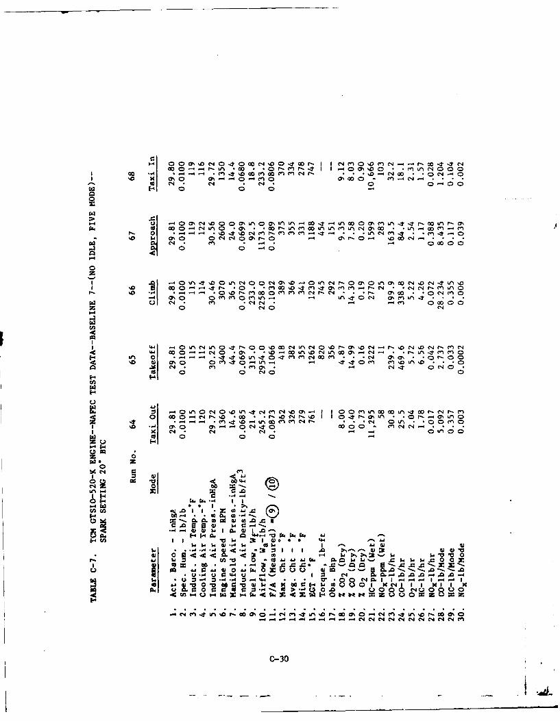
0- 00a% N 040 NN 0 IT=r-I IN MO '~o Wt 40- -4 - . W C C4 0 rO- M r- 4I1 -0 0% %0 0 *C WN 0 00a
0 -40 0 0 -%0 C -
4-F 01 -40; N C ;
N n0 % 00 r 01 ccn~44- *0 in * nL - 0 -- Lr-0 - oDt C4Mr-C nC- . .0 -4C I - Cn t i
0 -0 7 ,' 00 C- 0. .
N cn 000 000O ' - 0'
0 '4i * -1\ *0'% 0 N M \o Nr0 ' C- *r- 0' m *ng 0C4 DC4' N-- 4~ 0 0c' - ur40 M 00 * l O C4 ... 0 0 -- C4e
C CN * N-4 * -C-4C' 0~0000 C-O 0 N
44 O 0 C4 0 - ()S -Lf 0 4 00t D n 0 %C-4 C~ LfT C1CN en 't -4 cr) ocI-ion DLfi D ..
C 0 0 C-JO0 0
S- I 0 V) j 0 * 0 u N * -C4
\0 M0 M %0 0 r 0U * 0r- 0
~.ca C-'
1-4- 1-4
4 C4 9: I-~~~~ @"I*>
-4 010 .4 0
#442 II*4 '0~ Q)* r 44
*n ."4-4) 014-40)w w
ca 10to Aj c 0L ~ ~ I ' 4 CwsI~,, -- = =0**~~ 4 U--***--z-
0100 0)0 0u -0 0; '-w- Ad-4 r.44U 4N M,- 4A 4 A
I.. ~ ~ ~ ~ ~ 0 0 U '0 0 O1IoI44
cn 0 : C 1-
NC4~ 14 1; i' 1 0% 06 N4 C-~4 sf4 %O r9 aO 0%0 C 14 u'i' r- 1 0% 0C-0-4- - - 4 d 4N NC -
C- 30
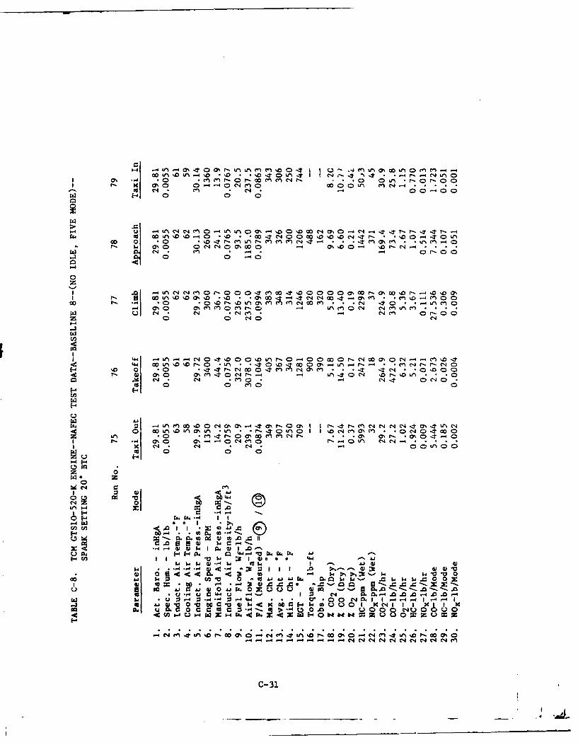
() *n0tn - % 0 - - %D T a L.* It -C4l- -4 C1 *I 0 -4 *0 *CV)e r ) ,co enJ *n *M *0 0- I - 0-0
0g 04 C) C- en 000-400n(n
c;~ 1-4 0c0
w 40 -4% o 40 I -- 0 0 U0 %0 %D %D0 N0%0 4N44 -t-- tL-00 0 004.0O 'D r- M n - n 0cn cn." 4 r-*en a,,40M
w N 00 *' -44 0 0%0- or4ooCL 04 ~ 'J ~ -C; *n *4rc 0 * -0
14- * Ic-). 0 0 O0 0 4 n4 o00 - 0 ON00r OrN - 4 D
-z 0 40 1
1-4
I4 0 n10. .01 0 - I00040000It 00 -0 L% r .- 4 -4r- - C4 Co --' .0 C . , w04mmNO m .. . N- 40 (c *L C 0
w 0I D n -* r * - N~ O-rD-A0..
0c 0 cn 04 E
-40 nIn(0 10 DC440,N1 , t I r % -r 4 1 -1 C-40 O -3 11 NI4 %0 OD UN * nO WN C~ *) 0 -0 0 M I C;.1 "04 O DO
0 0 0 c C; 0 0nMNr )x - 4 4 4t0C
1-4
z 04~~0ON~%-4%-0% ~ N N 4 % 1 40 01Of0 U A ** - 01 0 zN~%4 ** N 4 0
I 4 -4- % % N ~ 4 ~4L% N -
P-0 0 0
z 0
w $4
L) -4 04 44 I4 -04 Ij
2L- 4 .,4 m :3 4)00U0 V ca .lLW a w M05W cwwx0 0014~' X
LN Ao '4 "- * 6* * 0 0 0 4 00 M.0 'mcc Q -*4 U C:U4 U 1 I 3 C4 m 00. A.0.0 A-4 004w. . U -4 0 4" .. 4. -4 . .O r-0 C14 1I -4 -4 1l-4 -
u4 0 C I to a0 z 0-4 N 14 >4 0.% e 0 0%0 N 4 AO r 0 0
- -- - - 4NNN N N N4 N N N m~
C-31
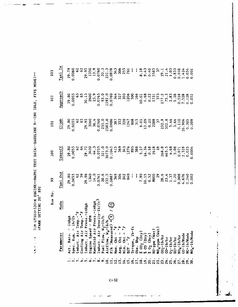
1-4 M LA CY 0 DL 0c 0 Mr V
I 0) -4 0 m 0 -4w m m 4r . . .u~ Ln c040x C- -4 a'0 C)c~ 00 0 0%n Icc CN 4 C4 04 eJ 0 0 C40
u- 0)i * r)M0O 0 a0 rm1a C4 M nm
rx 4 c 0 C f) U~O 'O 0 0 N D0% %0C4Mr 00 C* C~'~ 4 C 4 Le
* 0 - *OMr I 1 ,rlM - )- n i Lf LfO4I4 ' 0C C'0O4 ~ . 0'n- r-re' 0 0
-~0 0 C'0
-4
0z
ag p A'o m%'D *'D ~ 0 0 c, ~' -000 00V- C0 0 ' 0c0c enCC4U *9
z 0 0 C14~
44 00L O Or- 0 .L% r- (ON 00 C 4 * 0 r-C-4 C140 .() -t - n 4)MC400 M -- :- 00t -U * 0CD M 0 C
0D w ao C 0 m "t-- -4 ttt0 ' CO)L( *1 *o DV-1 C- c - * 1 .- *cn4 * -4 C14 It O C4lCO 0 C 0 0
E-4
0 L L 14m%0%. * % 1 r 0*W DO o0- ? It r, LI00 4
* C 140% 0 0 o ' mI -I 0 t % 061 0 C1 l * *0 r- t C
0% ~ ~ ~ - M 0~ Cl440 N~ 0 00 '~--x C, 9 * ' *D0- Occ 0) 0 0
0- E
0 z0
C4~ C, .
-4 ) ) I IDW Q
Ir w 3: 1 J 4)a 0 4-414 w m. I -' JJG
-. - i 3:0 1 0I, 0 )
W CC U*- AU -U-4 44 ,-4s -00 * -4 ~ 4-4 Dt 0 0 0 AC4 0 I1 4 4
C- 0% Cq X 1O4 -4 4 1 -4 -
-4 C, ~( N( 'N "(N (N M0
C- 32
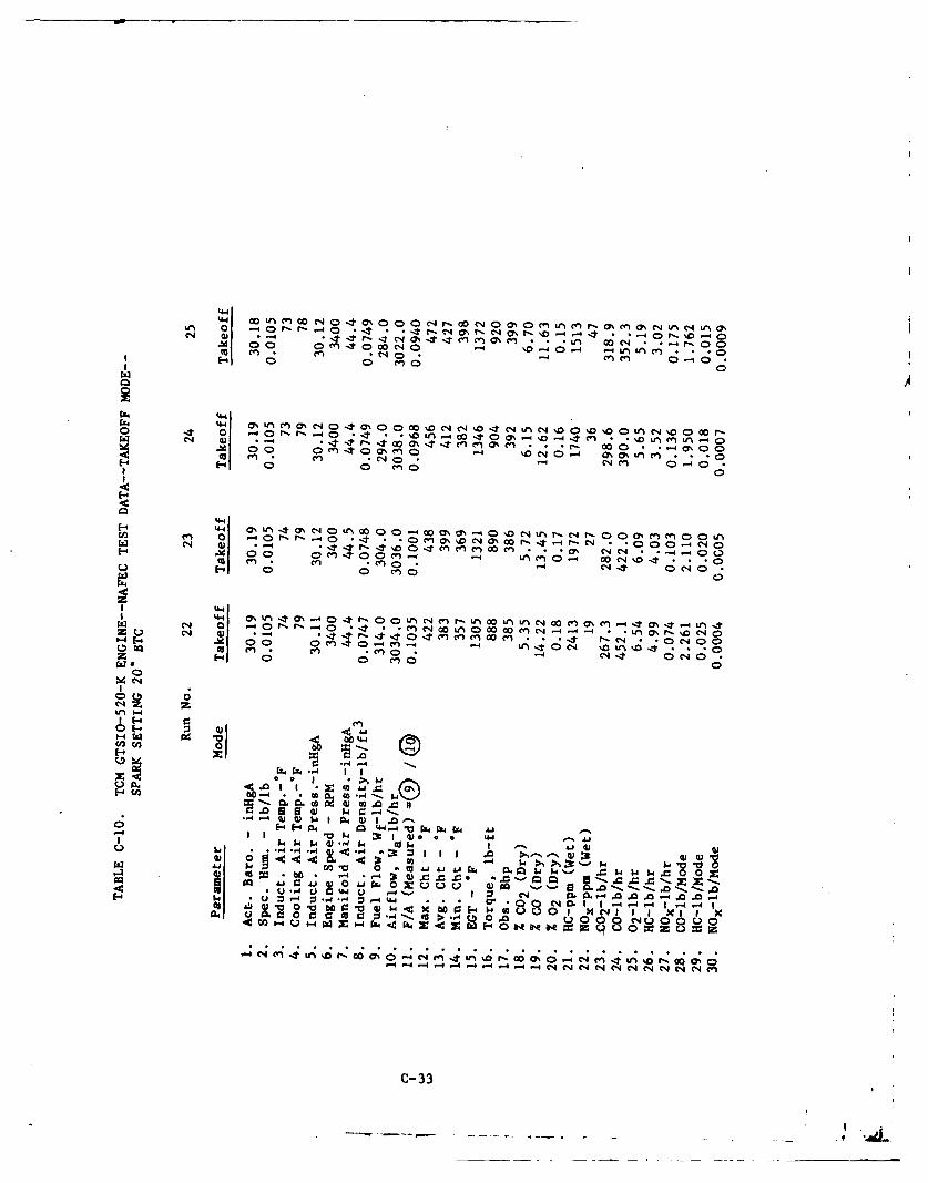
441 CoU j0 D0C. 'ttfiI*I " 0l - -4r I l -* -* - -40r-)'.O %0-4 CC**J r- 7 q(7 T T-n4 0 . . . 00 ~~ - - -*0 n- 00 Cb40a c"4 1.0 %-4 0- -4 Uj U'jcn . .*0cc C)Un- O C. C
4 ; *C4 0 .~
I~C1 ~E -4 0n 0 C4 0
zAra 4 M0) e % C ) 0 ' 0 0 e 4 %0 C 4 L ) C 4 D % f q % 0 r
Cc en C- *CNIO0"41 0(n0 -J- 0
E-4 4 4-
C-4 G- It * o c~ a It en* n0 n f , a% NC'404 fo 00 C) M0~ -4 ulC0 4 00 4'< *CcU n n . C'1 0 -4 - ~ 't Oe'Di0I. 00 cn C 0
M -41-4 00 -- Lf C4 n r- U' 0 rNWNN 00cM CI -' t (h' - t 41. - . -* C -4 M'4 U0C40 4 1 r 101z E-4 0 0 ()0
0
Rz z
02
W, r1-44
01-.E-4 Cfl
-4 q) $-A . 4-4 1 .
-4 .,)4 .4 &Cc-4M m (ULM.)0(1) 0 < < 4 < ( 4 .9 ,w$
U), U 2 * Q w
0-4 wC z 1-4 w -4 w Xz z IC4 0 Iu I
-- .- q " -4 -4 -- -4 C4e4N N 4 NC4
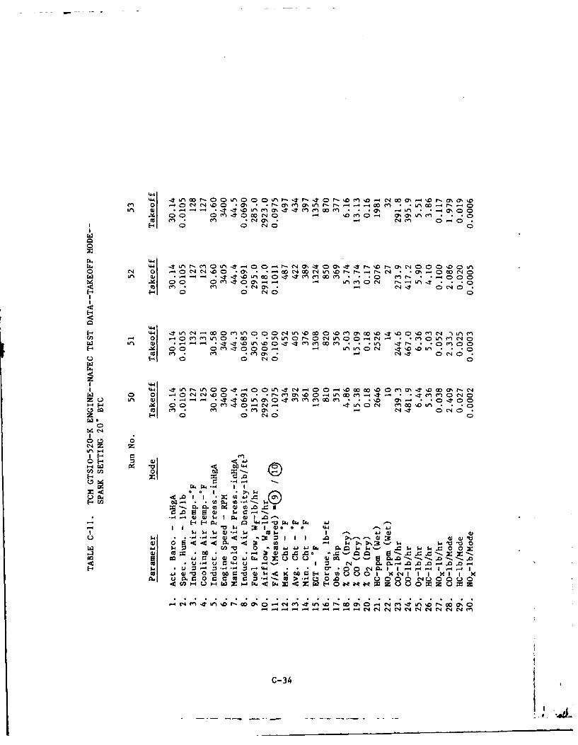
44 0 0 -f" r-- - r 0c 0 0 y 4% -a %
0- 0 * 1 ) a
Cue C(4 m C eJ *- 'd;~-4 0 (40 0
W 4n 0 4 I0 0 4 4 -n0m000 fn0 (' 4 0 -4 C"'4O C0) *; 14 I O t fC "0
44 0) o 0-4 00* 0 (4)' *n 000DN L D0 Dc %0 o t nC4- fU) 0 00 0(A4en WN 0 -na L Q 0C (N ~ A * C nC)C4C
m4 0 1 I 0 CN 0
00
44 .LAC' r- 4r 0 - r TC4 4L 00 nm' o 00~ m r- C,-4 0 (0C' 04 7 4 r m~ *o L O'0 'JLn M m -4 mC0L( 0 CJO
Cu u ~ W% (D 4%D , *4 m m 't ('1 0CJUa en 0 n c 0 CNJ 0
I4 4- 0 0 - 0 0004
14. W A V) 4- - -4*O ' * 0
~ 0 0 - CJ-4 -4 4'A c' 04DL a) 1HCu0 g 14- -4 "ca' W -T ('40(
I w - W 0 0 ('40
0)J 'C 0- t4
-4- U 4 4M . 0 0-
1- . 4 V 1 44 . . .0 1 4- -4 -.. 1co ~ ~ 3*- AI 0 0 I :' )w4 X b :E- . - l Mo
04u9 .0 0 0 ~ ccC 5 c -4u 0.4:0 I- Z * 1-4J DWWE4 e ,e z 0 x
1) 00. C4 C4 L II 1 9C
- 1-444 4 4- 4- - 4Na
- I I'V~e 3 I ). 0C-34
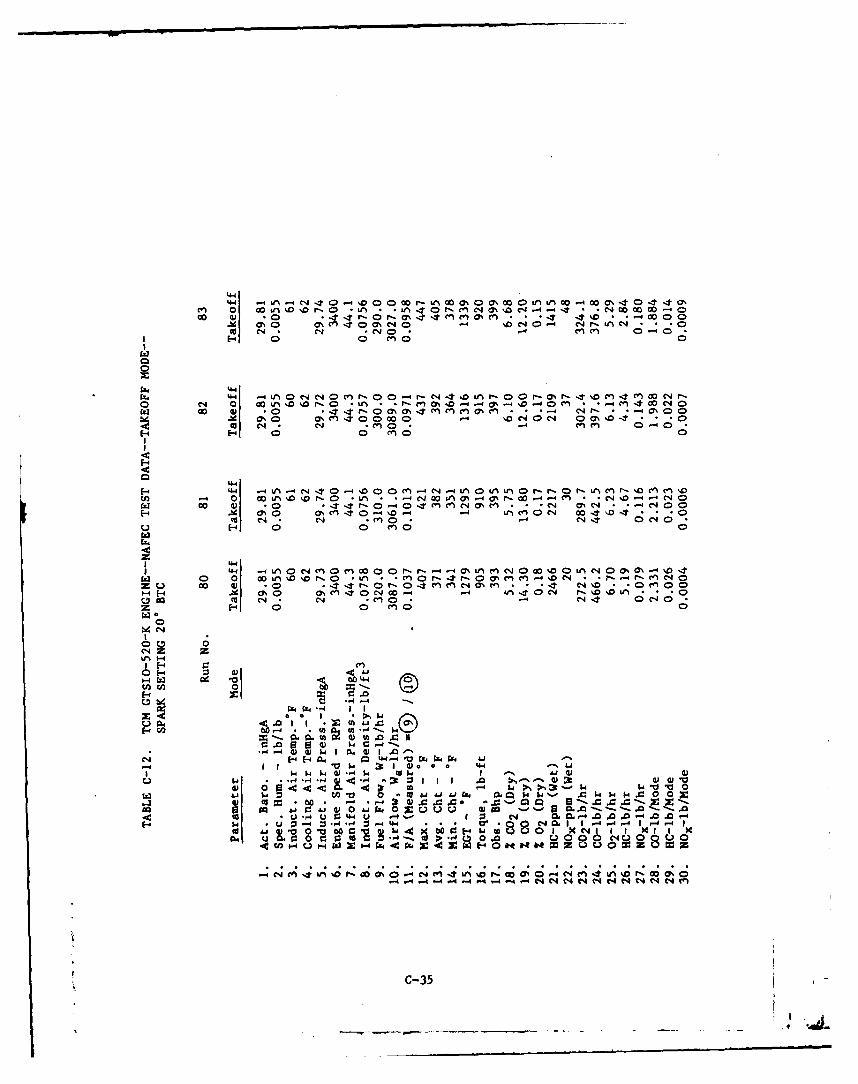
c.n 0 00 in%. o'r-.O L Ln f4 Cn CO. 4C0% 0Cd.4 -4 - -*C4 00 0000 O00 4) ' 0 e 0M 4 C; 4 4- NO
.M O0 0% - 0 C40 % C1 0 %0'0 .4 *l
0W - n0 , CJ *n C' - 0 4 r- - C n 4 c O.0(0 4 0 0 C I - 0 0 m 0enNr - 0 C
'441
V)00 '0 I C) -i 00 an <7% 4 0%r ' -4 M %1- - D-* 40w o-' t -Se 0%0 C.)~ 00 0 - '0 COC4 0O - NE-0 ~ ~ cN n' 4"o- 4 NM0 " 0 I D-oo *1 -4 C-4 C1 04
w 0 00 Ln '0o C-%0 i * -r en t-4 r- 0 cr-4On cn-4 %DC4 - - 0 -4 en 0Cz u o 0) . - r-0 M INC4 0%M .*C' OC J - - m 001-4 E- 1 ON 0 a, cn -4 %00- 14 in C0 C-4 0 .%D 04 *'
0 cat 4 *n C) * 0 eq -CC 4 0z- 0 cn0 0
114
E-44-
0 0 00if4~0~0C'-0 .fA * .00%~ C'% 0'
1-4 0 0 444
$4' $4$-to4--4- -H .4 :t 1 1 .
00- .43 c P%11I1
1-4 -4V % 41 40
0) 0) -. 4 0 I W . . . C 1 4 A- MC-I 1-4-4 0 '4 14114 1.C:f4 W_ r
OA to 44 0I u0 4.-I 0 P-.~J41. X U. " WJ0 0)WXf440H0HMO 8
W;34- 1 '0 C 0 C41 4 D C 0 0; I ;C4C44W;- r .0I.1. I.00-4-4- .4 -4 .00 -4 -4 *--G..00 ~% 04 N 4NNNC 4C
N m 0) ~.%.d~*---.C-35~.
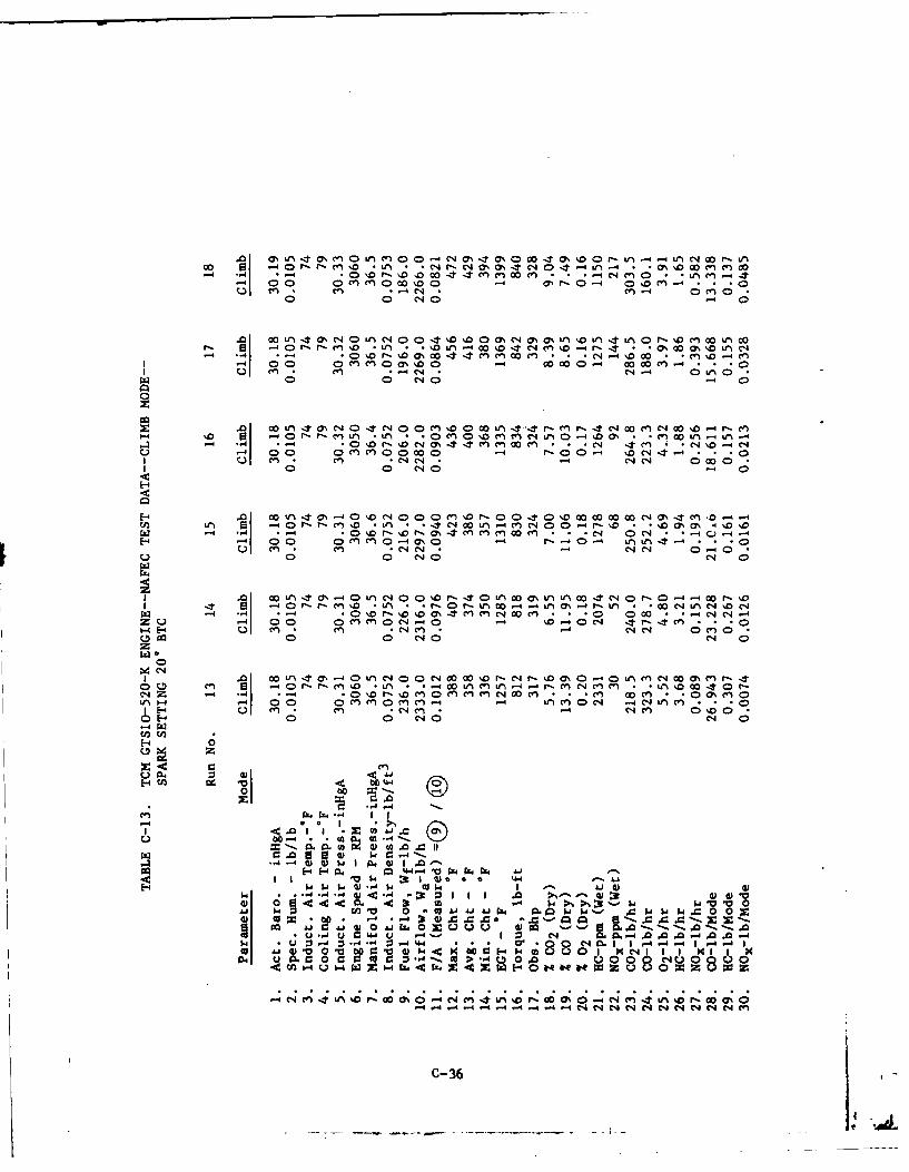
(7 un 'T 0s U-i o ( 00- o cjN 1 (7 o 0 0 4 43S%.o 0 i -i 4 .-4 UI N4 w r~- U-
- Dr D D0 n* 0 0% 0 -4- - 4 N * nc-4 C nC)4 o% r 0 *-4~J~, CO
* 4 N Cn q0 C1
-4. 0 P- r en o -L *Li-4 oo %'o 4'Jc-4 n o- r, 4 ac m uc41 -4 C; cc 0 % 00 0 C-4 ' 00 00 n 4C..
I -1 00 OC, C> 0%O -r cn . 0-4- ~C4 - 0 *
0n 0 C'J0 -1 1C4 00 0
~~( -4-f% Ul
-4 -. 0 0c0 o r-00r0M- e ncn0 n - N 0 14 -- 4 CU cn e 04 .C-4 * C'4 C14
C>0 0 C4J -4
M4 *-4 004 M . . e . ~ *n 0 !LA 0
z u-- 0 0 0 M e CN 40 -4 %D V04 M-U~- *1-4 - C1 en *CIJC en C*4 N 0 rn0
0 n0 0 04 0 C4 0
z0 0
-44 Z-4 .*0 r- ' 0 M M Cn4 e CA 00 0II - - -4en 0 vn -4 00 0') M 0ecn -4L 0C -4 Cc4 4% C *n M
I E-4 en *n-C4C -4 CJ4 en 0 C00 E0 04 C
00
eiZ ~ ~ ~ ~ ~ ~ ( - 4 - ~ 0 % 1
U.-4 - 4 0 0 k 0 C -Pk0e 4)Ui4
004 oil-4 Q) -4 0) t.) )
4) i 4
Z...4 m .I 8 .t j wV "@0 co V ak 4w
cc ~ o~ (0%) 43 A441-'- Q. u. U) 00 gz &.0. .011-. 0-
1-10 044 0U 04- 4 - 3JJC L-4. 0-Z -01 -,4 -444 . .o 4- 0 0 M 1144- 4 -
cc 0j w V C 2 : $ 09 -4 I-. to3' u9.0 1 4 140 0 i Io0, ~ -u*X9 o -4 CO > *0 0 .0-0 Q 00C4Q0
U...e . C _:U144L 14. U .- 4' I C; _: 0.4 .0004
4- -4 -4-4 -4 -4 -4 -4 4(4(4(1(4(4(4(4(4(
C-36
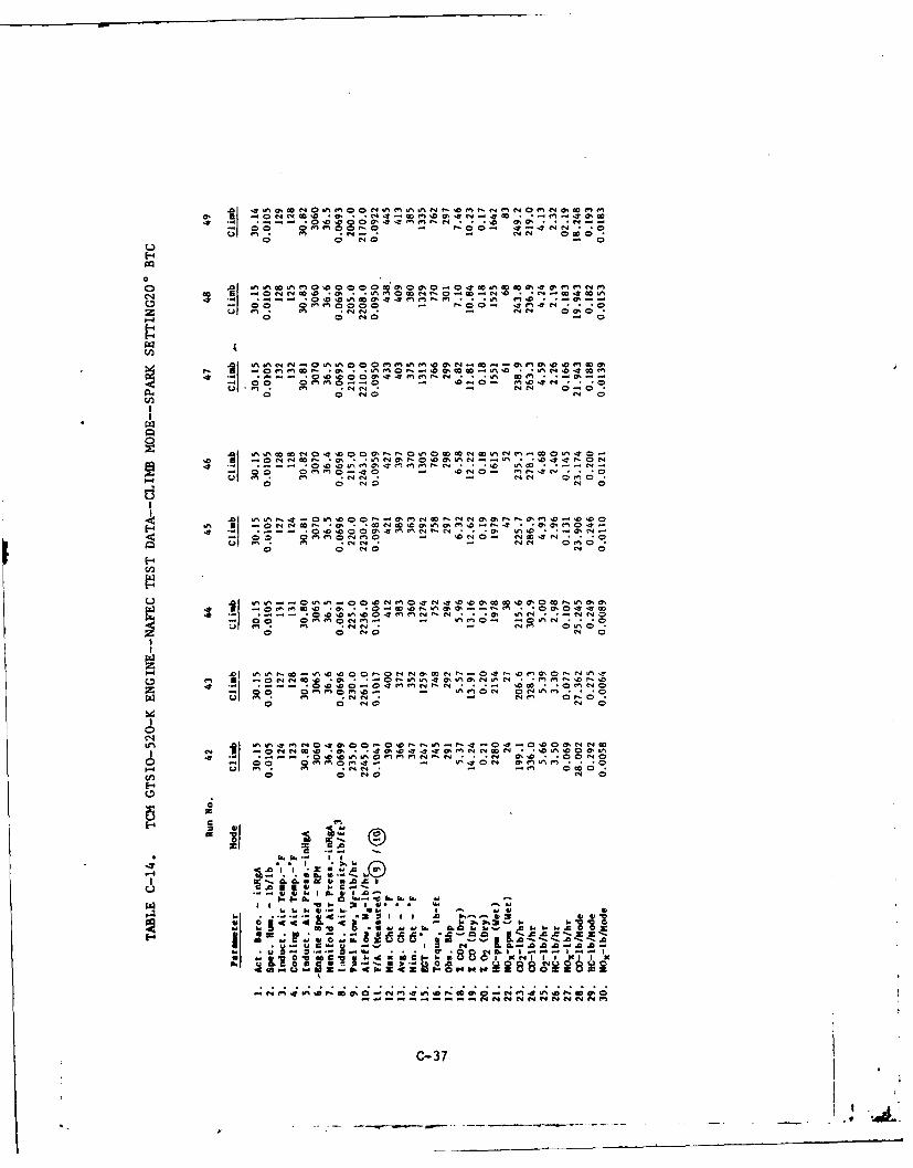
00 0 N - 0
E-4
00
*0u 04 -I M . .N ~00 A~0 0 - "0 Al0 I 4
00 ON C - 0n-
coInz o
00 OMO 0 ~ - MO4N *.
00
A C!
" - '0 N 0,
Z; 0 0 NOo M '
el m0N~ 9' " * 0 '
09 9 0 N N1 0
I- 1-0 060~
u M V*N A iU C Wm - NM A- 0
0 78 O.0 NO c
ON-4 a 4 a A; C4 NN'N".. 4 .; W4 0; 0
M I 0NN .0 ' *. N~ 40~C-37
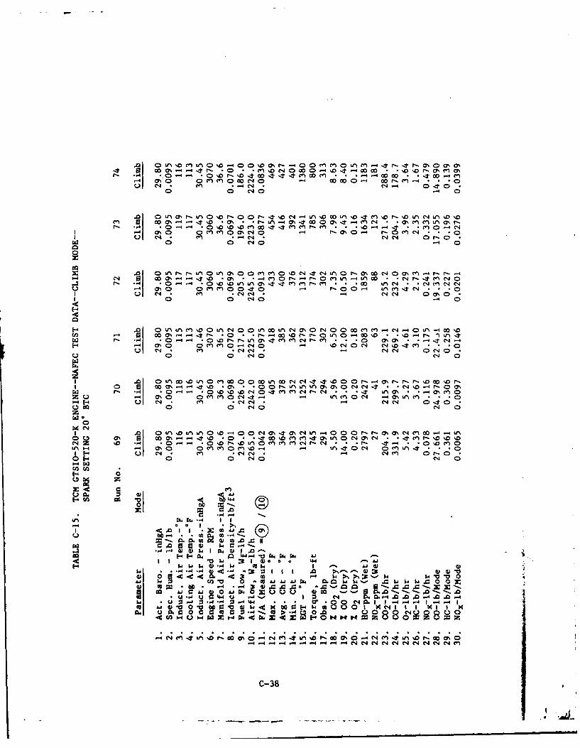
.0 n oe L %00 4 0 0 sr 40 m0 L M0 o. OCy 0%a4 0 7 O% -44 -Itr 0 ' ; *DC4000 t- 0 0 -- % . -0 naI- -'-4 ~ C A0~- w0 C4 44 C. C' - * .4 ~-4 O%0 c 0C.C04eJ 00. 0 rc-4 Mu C4 m 2'" *-4' -4 0410
0 O -A Dr -t oC 000 -n Tc o -% nC4 0D
r- -4 C)0-' 0 0 4 1 M cn r- en - 1 'O-4 -T4 * C1-4 mO%0 0 C'0ON N 0- r-0%- -0C. Q
I u C4 9 cn. *4 N *- ~'C14 0 r-Ow0 0; '40 -4
r- -4 0 0-4--4 -0 A -D 8 '1 a,.C'.4 M M r, M ~'--4 O'n 0C.C.0 00 -4 r-:.0'0-4 mf4't C' m--0 C
Un ()' : - 4 4(J' *-0 - r 40 I t - C4 000 -0- -*o -4r n
0; 0 nc 0 C-40 -4 000 )C4 C4 *e
Q- C01 CA00 C ' 0 0 L0-~
'-4 1 0 Ln0 DL 0 - 0U 0C4C4 0 0 r 4O -r W *' t i r-00 O~ -4 - 0 iDC. M - .0 0%' 0 r-L~ nLiC,(N 1 1 N -44(r- O
1-4 -,4 OC 0 %0 %D 0 4 '04 M 4 MC'4C N'~4C. -- "
1.4 E4 ) 4 en C. C-4 C-4 . -4 0'4 eq 0 4 aU00 '10 C'J 0
00 ON ~. 4 *D - 00 %0enUn-*OL% 0C4OC4 M-% D%U ~ ~ -4( r- %D 0.--- 0 .'O 0 04 ' MC-' -n M -4 P- 04-0~
'-4 M M C0(n %0 -4 .- 4 U 4C;r,-, C (-')4 -9l ~ Cu eq m C;. -C14CJ-4' C44 040 -r
00
go .0
01-4W,- 0W NO(-4r41
04- UZ2- 1- I4
0. 4 0. 4 Z -14- . .0 . 0 4CL1 1-4
to J C II M~- 60 0~. E-4- W AU 0 I I I X
.4 en . U W x p ,.4 Ak z C.4 0 .-. 000.40.
14 - 4 -4 4 - -0 ;_ 4C .4 9C 01C 0 C'4 1-4 -4L 1-4-41 0 C
- N'1 i'. -'. 0 - 4 -4 -4. 4 -0 -4 - -- 1 N0-4 N' N C4 Nf' '04 r- C4 M
C-38
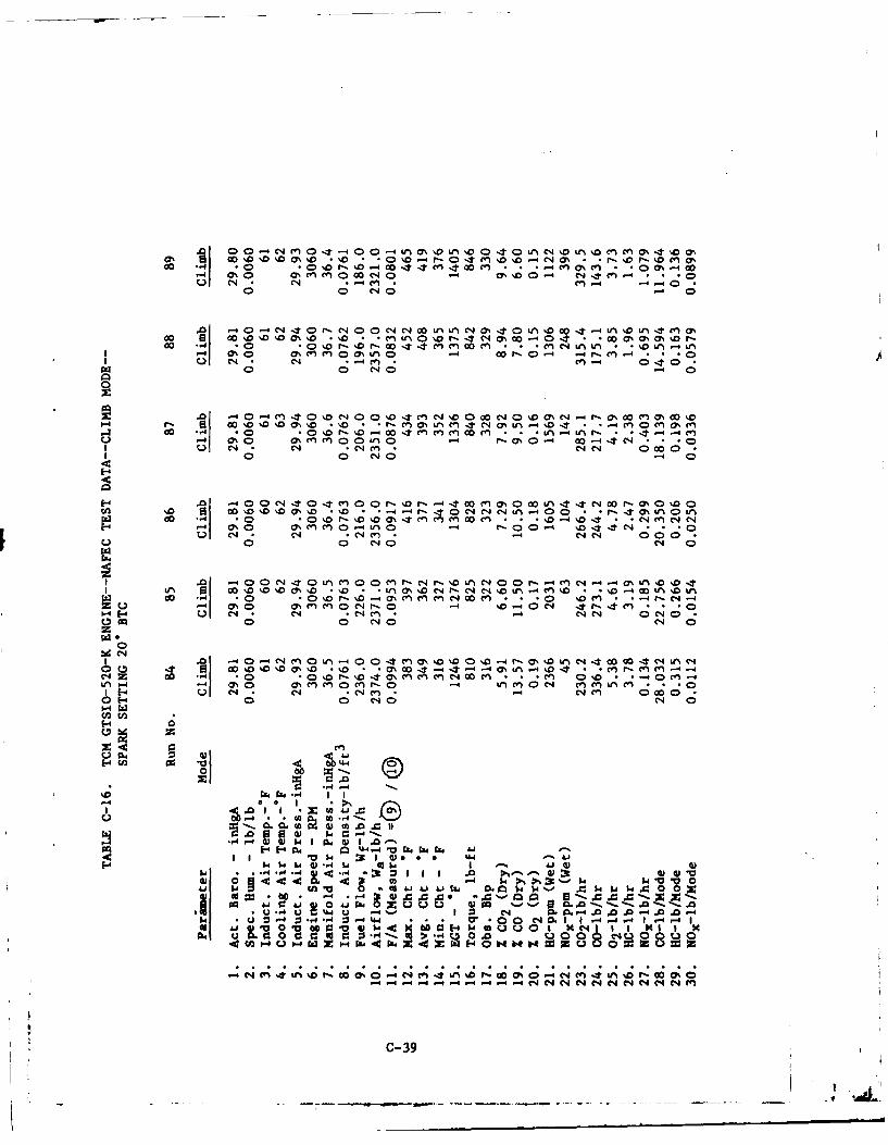
%0.n0 0 0 4 0 - u 0 0 0 N, L MMOS4%0Goo%~ M ~'''0 'o .0o * 0'- r- 0 't (n%0,0-4 C40 M * ,% r--'00 en0%
OD ., .0 1C a % 00ItIt en 4 0cn * - -40n%(m . .00% -400-4 O%0 C O ( en 0 C4 0 -4 0% %D 0-4 eq4C en- *u C- * -4 cn . C) 4 -4-40Z
-4 -4 - N0 C4 0-r n 0 ) C %00.t - L D 0%t(n0co 0 0 o '0'C0%%0 %0 - *C U A0 - 44 M00~-0 O * - *Qo0% (% M%D r-
I-4 0%0 0CC40 uo M 000 or-0- -4 r- M -4 . 0
0 0 N-4 (D
o -4e' 0 - o -0 o N D 0 '.0 4 C-) N- .0 0 00 Nj 0 'D ON - 1 - M% 00 Cn CY% 00 %0
0 4 C4 * cl) 04 0000CI 00 CNO -
oo .,4.0 00 4 4c 40 % ,% oO cl " V)00 0t.A . 4N a -. 0% .000 -4 a%0 Ch0'cn0'0 0% 1 0c *- *n *.-4 'D4 -1 N .
-" 4% 0 UCA M0 4u0 M--Nr DL 0 0 r 4 4 M *n 'D%0r 00 NO %0%0 0%% D -- *)0%DC -C4C . -4 NN %0 000 DI
o0 -4( 0P 0 - N c c N 00 l 4r
I cc .~0 N40000014 C0%uC0 4
0 000 0 NDDa%% o ;O 000-.- 0 * -4 'T *4 - * *0 '0' *a C lr e 4r4Z0 0 0 C0, cn C4 0 - n .- tO en4( * *
Ln1. - 0 0 0%MM0 NO- N 0V nL M .. (
.0 E-O 4 C 0 % 0'0 '0 4 N f0w4 I 000'0 ' '
E-4Iz
04
0040
-w **4 -4 *
to N 0.0-
V w M4 1 4V
41 .. *.4 M 4.4 4 M 0
:4 * 60 .- .4"4 -44.4) 4 . 00 1 0 -4 .0C -- d
.4 -4 QO %Wu ~ "4 10 0 004 040 A
u- (' 14 :1' -1 004 0 04 N 4 80P 0 C 4 N. 1 1r4 Ui' .4 00 0% 04
- -4 -4 -44 -4 4-4 -4 -- 4 N N N N NN N M~
C-39
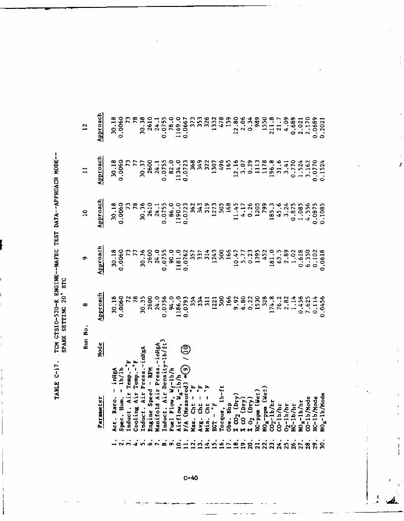
0~~a .- %I-rc%- * o 4 U%~ ChI 0 *-ma %inJ 0: r0 U'% .- N M * % 0MMu,4
C-4 C, 00 oce~ r- 'o0 M -MM CN C ON Lt. % j.ot *
-0C1 0 -q40 00C
(- C1 .0C
M -40I- r- .0 *4Ln MC r- %D .. t'J0%s 0 - en 0 0 " 04 0 * 'ArC4 Jr-r-M -Ll -CND- C4 M%0- C C4 0. - *r- CIA -. r-.t4
C; 00 0 o 'J~~ 4--"4r-MnMM4 -4 C4 C4 -0-4f r,N4 01 0 0 -) D 0aAc 00
04
I-' m In * -4. -4 -D4 -01 N0 ,L;L 00 W,.Pi*C0 10 r- r- M M NLfn * N *'rLf0tr * 0'%A0
0 0 C~4C4 0 00 4 - 00 '1
r % 0 0 0 00Nr - m -r nC40U)mN C
1-4; c -
44-0
F 0I- H 4*-
43 0 4
$ 0 ~~rrc0 C4 f 0 0''%%'C~~ 00 0 -4Lf CJ.Lf4
C4u 0 1 cne1n -4 0 ; =
rnI W
VV 'Al "X~J
00 ~ ~ .0 of *14 ~ 4 J
CC 0 .02 N' 4@
1-4~~4 -.. *0 ;3 r140J W' 41. ~ ~ ~E- 4 4- -4 ;3c -4 k ~2cV
004,CC 00 V-- -~. = 0
I.. 4 U ~- .4~ -4'4 * = .0 -- 0 QO2 I - 1A; AI W4 0 aK Wc
V .. 4 o 9: 4 U :3 04 A 0 0 0
a4 0 C14h~0 "~ 000 04 Z 411 t 0% 014 0 0 %% -00 0
C-40
- - _ ~ ___ AL
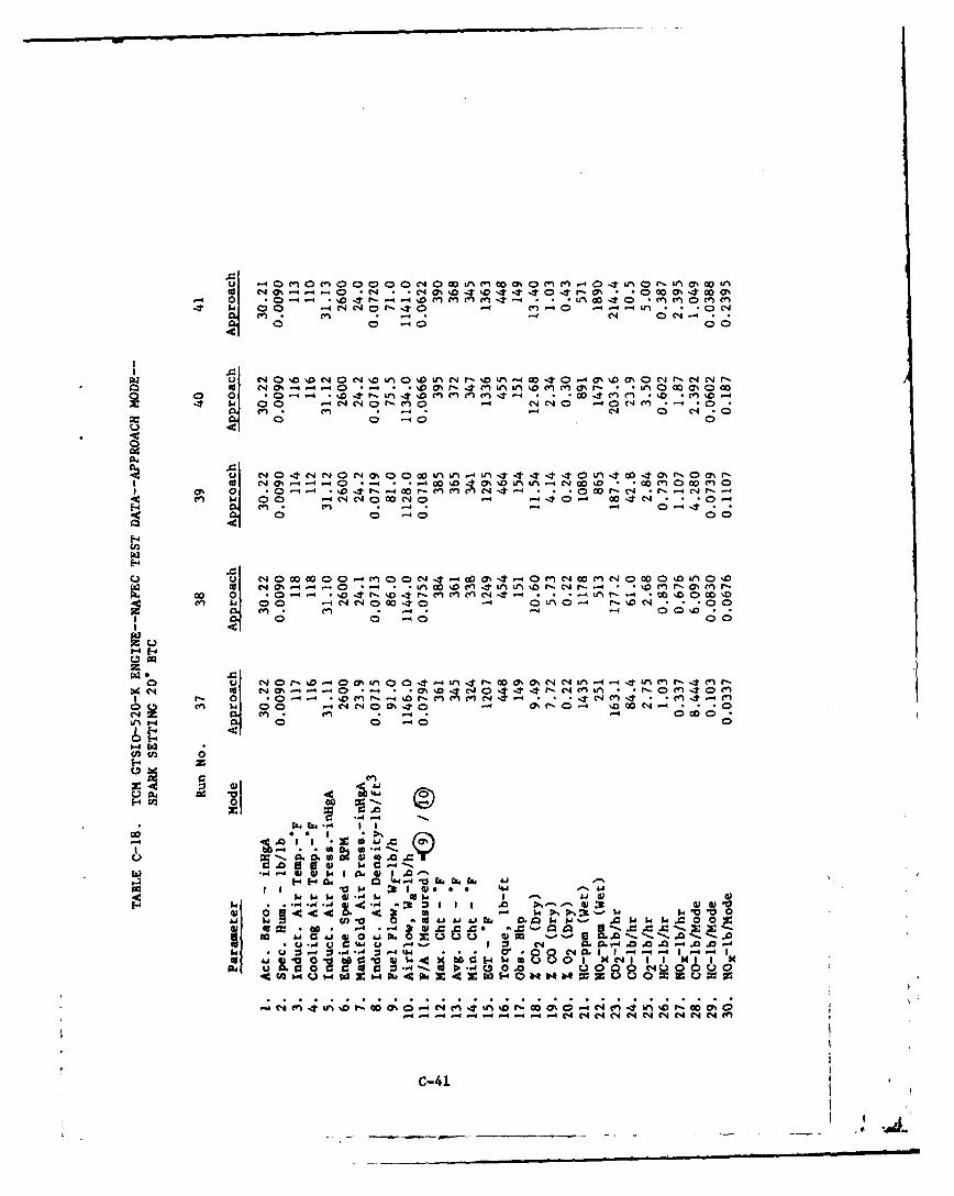
W0AM ) 0-o-- M~ Mc~%%~% *t -4 0 'T on0* nCNo% 0D 40i- %D -4 4 04 r- 04 'm m
0 0 0 004
0 0 C' O % 4-1 C-4*
cn-4 C1 0 C4-
N- nL 4L t 4- 00 0J'o-~ -n C'.t~ .- 0 (7 *- 00%
cn 04 0 00C- 0 ; (01C
0 C
F4
0 ' 0 00 000 * -4 enC )*j 0 %- 40m0 0 W 0 n0 %DI-I M1 _4 _4 _4 0 _ % 0 . TU% F.oP C4 - %0 )rla M
00 0 - D - r-cnc C.) C'4J-t -4 -* -4 T-0 -A *- c 0 o %m~ -4C- e 00 1 4~~C 0 a 4 *40 -4 r- D C4 ..
4n M4 0 0 0 %000 C1
P-4 40 m
C, 0 r0 C %D 4 00 4 I w 00 O~U % rN F asC40 * 414Ituie -I nfC4e ON0 -C4ML *0- 0 Cn -4 0 C0n
0qC 0 m 0 00 0
C~~~C C -. 0
04 0 -0cn- ca
01-0
(ICi 0
04 I4~4 - - k0 4 &
-.r 4 ..4 u. m - I I A004 ** a. **, 14!N1
-o 4. I I *z iJ 4 (
u 1 -0 u 0 N -4 dJA
i- 5.4 $4 x4.* U 4~ ~ I I ~ ~ ~ ~u 11 *4 4P '08 -4 1,. '0.~4f . 4 U 0U w 4- am a~b m'.'
-4 U in~& %0'. C14~~~ N U4 eq N 0-44 *4 N 00 m'01 I~ 4 4
C-41
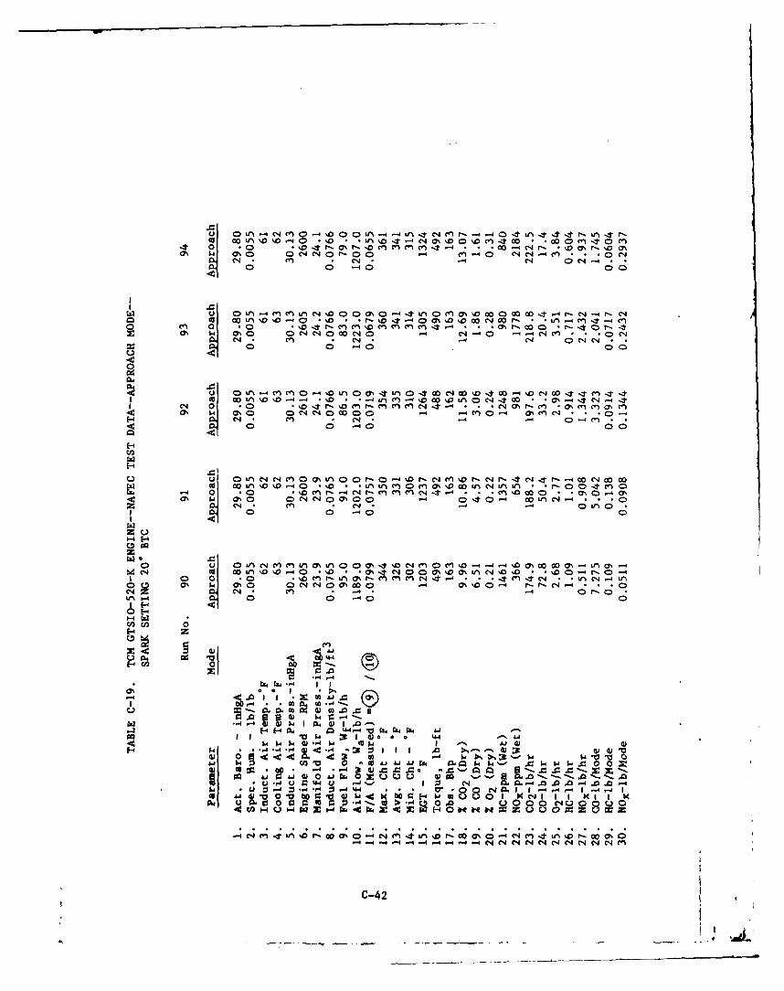
0 u', - 0- 000 U - -4 i n 4 r ~F -. 404u444r- n UN r-O %O aN *4-4%.0c m w *, 0 'T0 m
*0 * 0 "04~ *N *D *cy * %- ,CIN0 O4N '0'- 00 COD m ~4 m m C; 4 'ON"
* C; (4 * O -0 0 -'0 00
uI kA - nL 4% %0 - n0 M(S 0a0 0t- -C 4r00 L1 %"40 0- 0 4 0* .- % 0 'T -40 0% %0 00 00r- 0 Lr "' * 4 4 C.
0N 0 0*~4 0Ci0 ,ci4 1.4) . .0r~ C-4 t- 4
0i14 ,04% n en4t~0 4C014- 0 0 CO 4 C 4 4
Q r mCN OIn04 tl *00N0 % *00-1* C1 00%I ItC'J) 401 0 nIDO -4 F-Cc in en 1-4 -0 LA4 IT c~0 %r.-c -* oC*0I (;0 00 -- C- C)" t .C4 (7% (7 *cn(N(
N C; C. V4 Q4 en4 0
E-4
U 0 in~ " N c- 0 0% Un 00 - 0CD . r, C' M 0 r- Nq Ir 4 C,4 Ir- - 0 C-4 00 CO-40 OI - 4% W nM0M 11 0W C*4 UN LI r- C!' O *0 0In
0%00 OJO %00t- - C-4 0t0- 4 2 O~- '0" '.0 C; N 0N00 > 0u -
4-4 -4
1 00 a *0 D r l 04 4 *C 4n W *4'L0% 41 % ONNO % O 54 m'004 r_ C.4 CD
Le 1- * 0 -.~0 -0
I I Lpj,
92 <.09 m * ) m .0 c it
FI 04 g 04-4 4 4 AW 4
V0 64 3: 1 a 0 0 LwO p $4 (k -4 Wee to 4
.,4 * * -4 -,4 .<,4~ I) I 3 0) 0) MAj $ aV 0 t wA 0IAi~o IN .0 $4 ' W 'd $4 w0
CO ~~. uW~ r..Z r ~.'-00 U PQ0-U~~0 004 U40 Iq ;f Q -4 I 4 I
0, -4 o:03 *'~m 'c 0.4c 0 0 o ONOOU
.4 0 v ~ M ba 0. p. w 0U 0u 1 x~4U 0C-0 %0. C 4 U 1 1. x I% 0
C-42
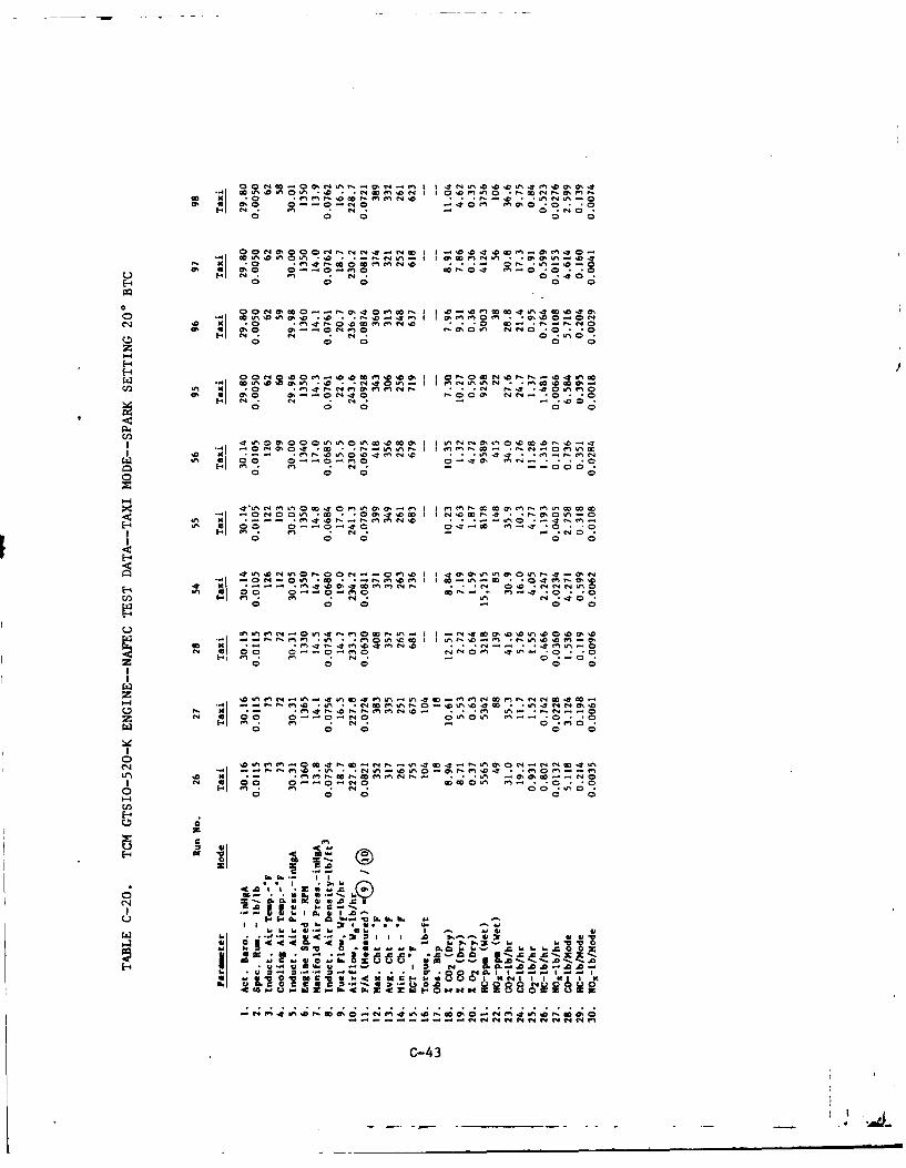
0 ~ ~ ~ " No A I N ~ 0~
11 Ch N. -90' Da 0' mNoe9A o 0 0 0
o I1 N -"No -0
E-400 00 0
UP 0.0 C N~ -0001 IN O !0
o C. 0 0
0. A A N0 - -. 0E-40 0 0!
Ct Ol 000- 0 m40 1N- In 4.0
o 0 0 00
co C
~ N'~~ 00 0 ~0. . I ~~ N~ 0.~ ~ ha
1 -. 0N00~'~ 0 .1004 1?ON m~.
NI~ ~ z co~N 1 I ~ s m~ ccN
C4 9 mI~ N . 'I 0h 0 *NNC r.
%nN xU No . 0
a~ ~ ~ 0ca A E
-'4~Ol *.. CL : 2! : .1 . 'Ne0~ . , ft .,4 N .
o~O m II INN ~ N .I AI w
N~~ 94 00 f4N 0 0 f4 on
11 ~. N -C0-43
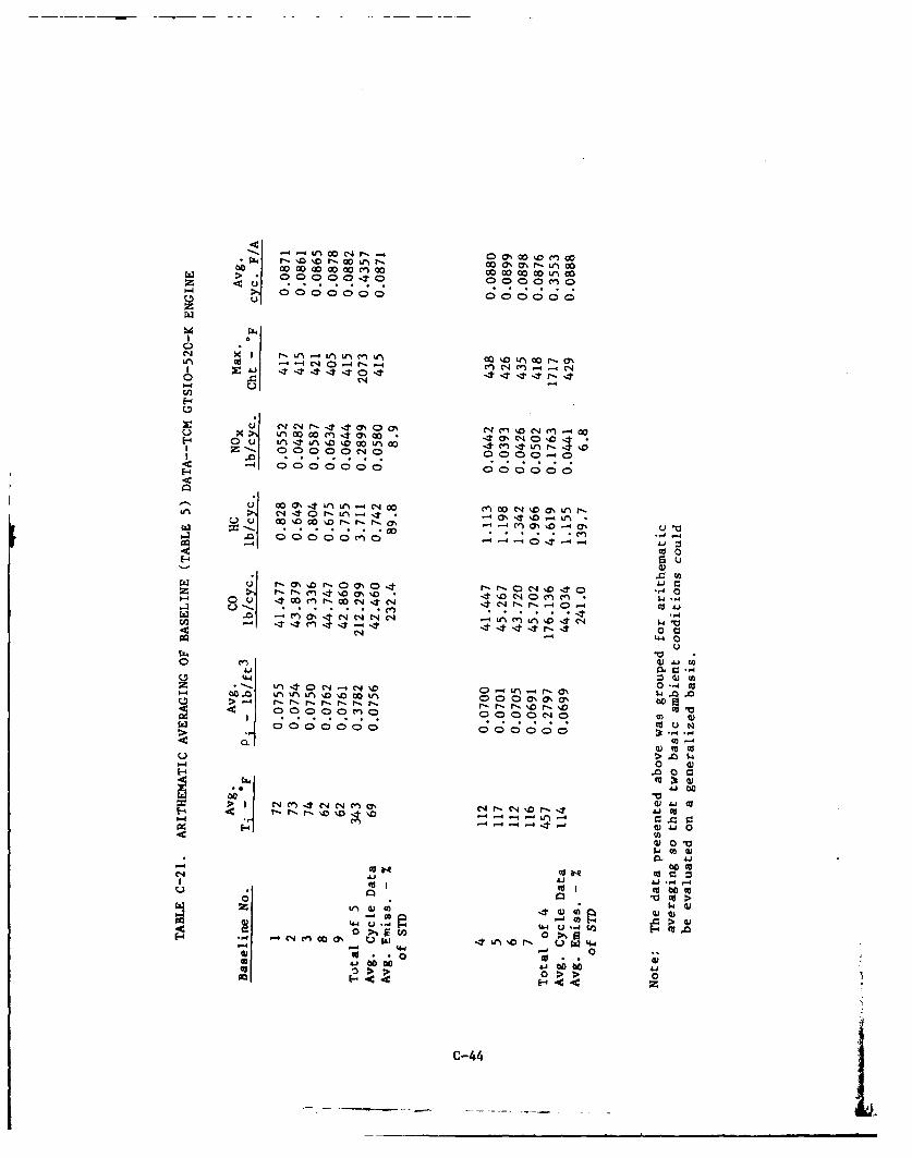
raw f* I 0 0 0Q 1-0 0 L r 0 o o en o
000000 00000 n00
0 .) Cd e 4 -4 *
C.,4
I I 00000 "o-~ 0000 0
- 00 0000' L C00n 000000 mtnr
-m ON1 %000 .~ ON u0~
CYN 0
Z- ou4 C4 C- nM l1 * C4"V3 ~ ~ ~ ~ -44t ,
.UU044~ 0 J.. C13
Lfca0C..) N~
00 0CD0. 00000C C; ;C;0t 4-
030W
Jbo
0) 003tLfa)
w 01
- a lt~ to =0)c
o I. 0.. 0 m
C-4 I4