Embed Size (px)
Citation preview
33. UPPER SLEWING STRUCTURE
33-12
33.1.5 COUNTERWEIGHT
33.1.5.1 REMOVAL PREPARATION
33.1.5.2 REMOVAL
33.1.5.3 INSTALLATION
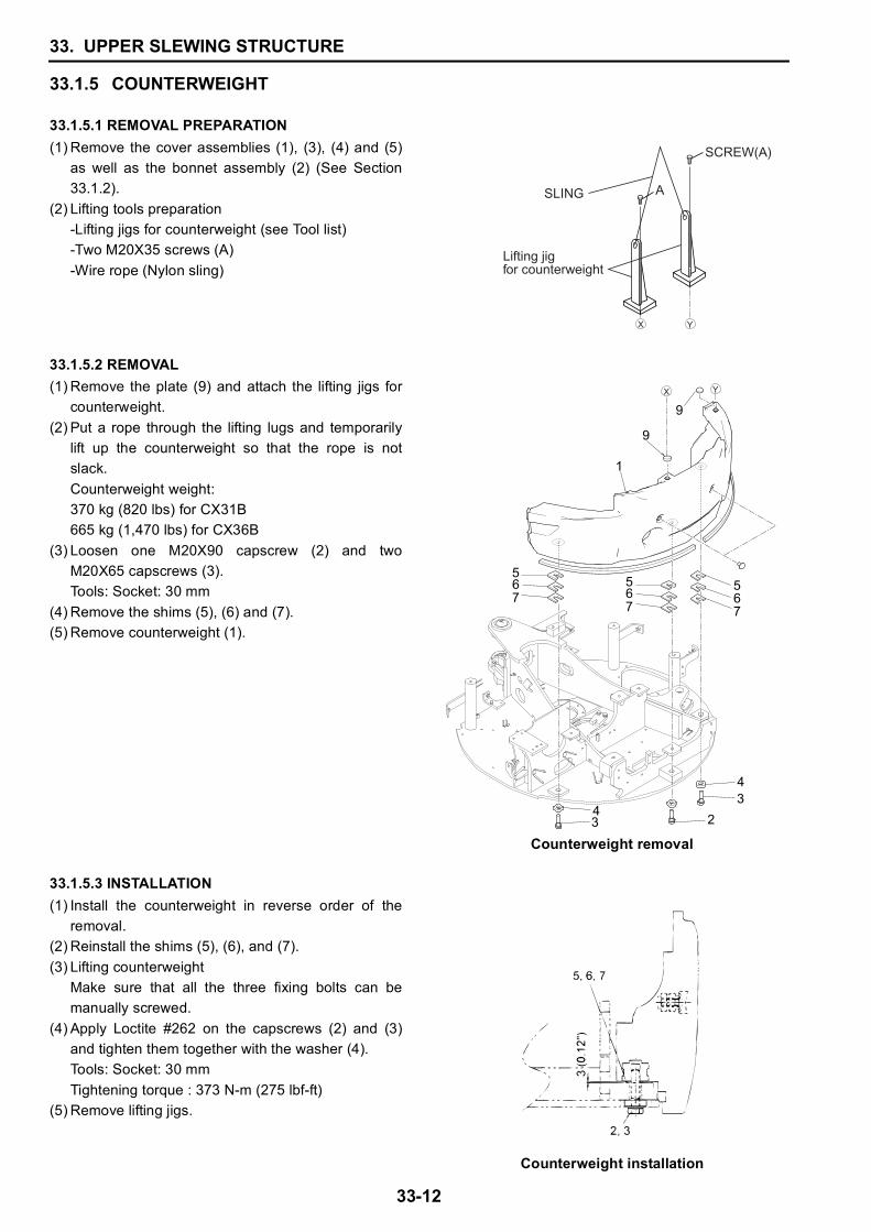
(1) Remove the cover assemblies (1), (3), (4) and (5)as well as the bonnet assembly (2) (See Section33.1.2).
(2) Lifting tools preparation-Lifting jigs for counterweight (see Tool list)-Two M20X35 screws (A)-Wire rope (Nylon sling)
(1) Remove the plate (9) and attach the lifting jigs forcounterweight.
(2) Put a rope through the lifting lugs and temporarilylift up the counterweight so that the rope is notslack.Counterweight weight: 370 kg (820 lbs) for CX31B665 kg (1,470 lbs) for CX36B
(3) Loosen one M20X90 capscrew (2) and twoM20X65 capscrews (3).Tools: Socket: 30 mm
(4) Remove the shims (5), (6) and (7).(5) Remove counterweight (1).
Counterweight removal
(1) Install the counterweight in reverse order of theremoval.
(2) Reinstall the shims (5), (6), and (7).(3) Lifting counterweight
Make sure that all the three fixing bolts can bemanually screwed.
(4) Apply Loctite #262 on the capscrews (2) and (3)and tighten them together with the washer (4).Tools: Socket: 30 mmTightening torque : 373 N-m (275 lbf-ft)
(5) Remove lifting jigs.
Counterweight installation
A
Lifting jig for counterweight
SLING
SCREW(A)
3 4
2
34
9
9
1
567
567
567
33. UPPER SLEWING STRUCTURE
33-13
33
33.1.6 PUMP
33.1.6.1 REMOVAL PREPARATION
33.1.6.2 REMOVAL
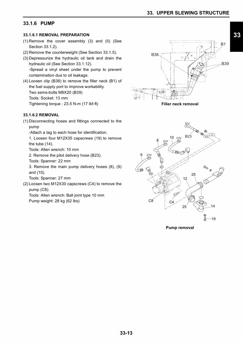
(1) Remove the cover assembly (3) and (5) (SeeSection 33.1.2).
(2) Remove the counterweight (See Section 33.1.5).(3) Depressurize the hydraulic oil tank and drain the
hydraulic oil (See Section 33.1.12).-Spread a vinyl sheet under the pump to preventcontamination due to oil leakage.
(4) Loosen clip (B38) to remove the filler neck (B1) ofthe fuel supply port to improve workability.Two sems-bolts M8X20 (B39)Tools: Socket: 13 mmTightening torque : 23.5 N-m (17 lbf-ft) Filler neck removal
(1) Disconnecting hoses and fittings connected to thepump-Attach a tag to each hose for identification.1. Loosen four M12X35 capscrews (19) to removethe tube (14).Tools: Allen wrench: 10 mm2. Remove the pilot delivery hose (B23).Tools: Spanner: 22 mm3. Remove the main pump delivery hoses (8), (9)and (10).Tools: Spanner: 27 mm
(2) Loosen two M12X30 capscrews (C4) to remove thepump (C8).Tools: Allen wrench: Ball joint type 10 mmPump weight: 28 kg (62 lbs)
Pump removal
��
���
���
C/VP1
C/VP2
C/VP3
A1
A2 A3
14
19
12
108
9
25
25C4C8
ZA4B23
S/VP1
33. UPPER SLEWING STRUCTURE
33-14
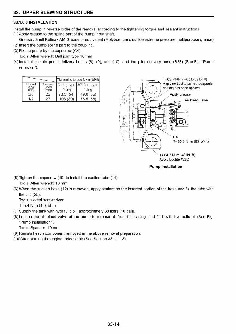
33.1.6.3 INSTALLATIONInstall the pump in reverse order of the removal according to the tightening torque and sealant instructions.(1) Apply grease to the spline part of the pump input shaft.
Grease : Shell Retinax AM Grease or equivalent (Molybdenum disulfide extreme pressure multipurpose grease)(2) Insert the pump spline part to the coupling.(3) Fix the pump by the capscrew (C4).
Tools: Allen wrench: Ball joint type 10 mm(4) Install the main pump delivery hoses (8), (9), and (10), and the pilot delivery hose (B23) (See Fig. "Pump
rermoval").
(5) Tighten the capscrew (19) to install the suction tube (14).Tools: Allen wrench: 10 mm
(6) When the suction hose (12) is removed, apply sealant on the inserted portion of the hose and fix the tube withthe clip (25).Tools: slotted screwdriverT=5.4 N-m (4.0 lbf-ft)
(7) Supply the tank with hydraulic oil [approximately 38 liters (10 gal)].(8) Loosen the air bleed valve of the pump to release air from the casing, and fill it with hydraulic oil (See Fig.
"Pump installation").Tools: Spanner: 10 mm
(9) Reinstall each component removed in the above removal preparation.(10)After starting the engine, release air (See Section 33.1.11.3).
Pump installation
73.5 (54)108 (80)
49.0 (36)78.5 (58)
Thread size
(PF)
Spanner used(mm)
2227
3/81/2
O-ring type fitting
flare type fitting
Tightening torque N m (lbf ft)
33. UPPER SLEWING STRUCTURE
33-15
33
33.1.7 CONTROL VALVE
33.1.7.1 REMOVAL PREPARATION(1) Unlock and open the right upper cover (1).(2) Remove the right lower cover (4) [See Section 33.1.2.1-(3)].
-Spread a vinyl sheet under the control valve to prevent contamination due to oil leakage.(3) Release the residual pressure in the circuit and the pressure in the hydraulic oil tank.
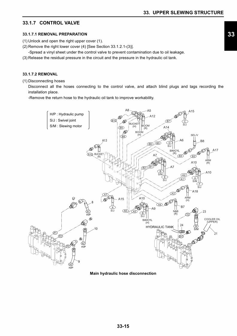
33.1.7.2 REMOVAL(1) Disconnecting hoses
Disconnect all the hoses connecting to the control valve, and attach blind plugs and tags recording theinstallation place.-Remove the return hose to the hydraulic oil tank to improve workability.
Main hydraulic hose disconnection
S/JE
S/JF
S/JB
S/JA
S/JC
S/MB
S/MA
ARM(R)
ARM(H)
BUCKET(H)
BUCKET(R)
BOOM(R)
BOOM(H)
B1B2
B3
B7
B8
B9
B10
A10
A7
A5
A3
A2
A1
A6
SW/CYL(H)
A17
SEL/V
B8
A10
A10
A18
N&B(R)
B7A9
A10A15
A12
A5A8 A15
A7
A7
S/JDB5B6
SW/CYL(R)
A6
A14
H/P : Hydraulic pump
S/J : Swivel joint
S/M : Slewing motor
8
H/PA3
H/PA2
H/P
P1P2
P3
9
10
A1
21
23
24
COOLER OIL(UPPER)
S/MMHYDRAULIC TANK
T2
Dr1
T1
B4
A4
33. UPPER SLEWING STRUCTURE
33-16
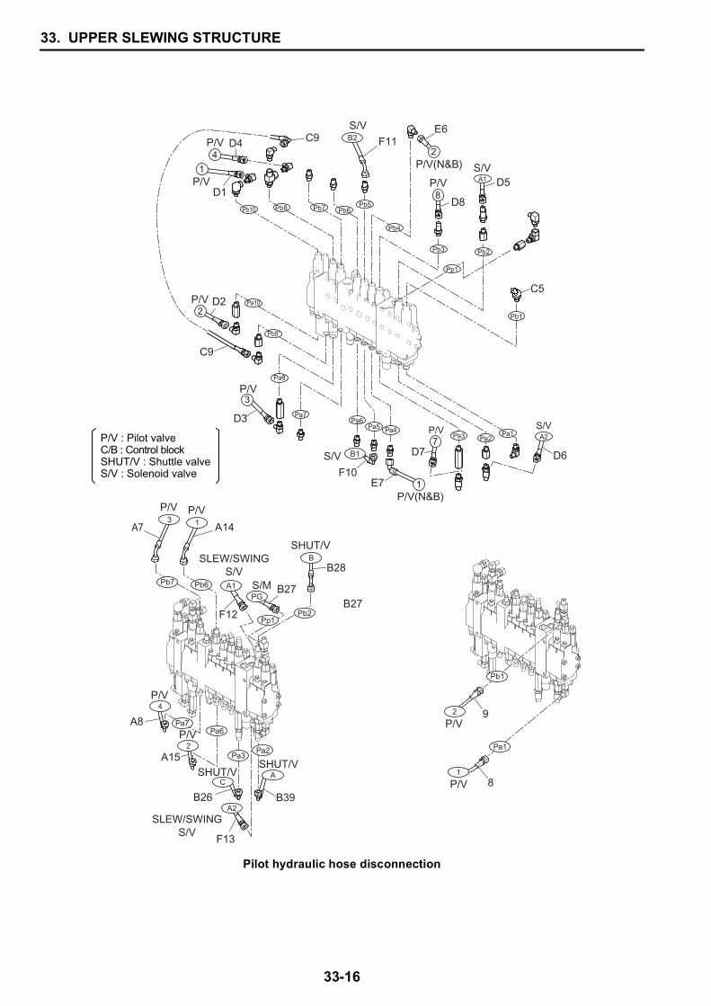
Pilot hydraulic hose disconnection
P/V8
2P/V
4
P/V1
P/V2
P/V3
P/V7
1
S/V
S/V
C5
D4E6
D8
D5
Pb10
Pa10
Pb8
Pb8'
Pa8
Pa7Pa6
Pa4Pa5Pa3 Pa2
Pa1 A2
Pb7 Pb6Pb5
Pb4
Pb3 Pb2
A1
Pb1
Pp1
C9
D1
D7
E7
D3
D6
C9
D2
P/V(N&B)
P/V(N&B)
P/V : Pilot valveC/B : Control blockSHUT/V : Shuttle valveS/V : Solenoid valve
A7 A14
F12
A8
A15
B26
F13
B27
B28
B39
SHUT/VB
SHUT/VASHUT/V
C
F10
S/V B1
S/MPG
B27
SLEW/SWINGS/V
SLEW/SWINGS/V
A1
P/V1
P/V2
P/V3
P/V4
Pb7 Pb6
Pb2
Pa2
A2
Pa6Pa7
Pa3
Pp1
P/V2
Pa1
P/V1
9
8
Pb1
F11
S/VB2
33. UPPER SLEWING STRUCTURE
33-17
33
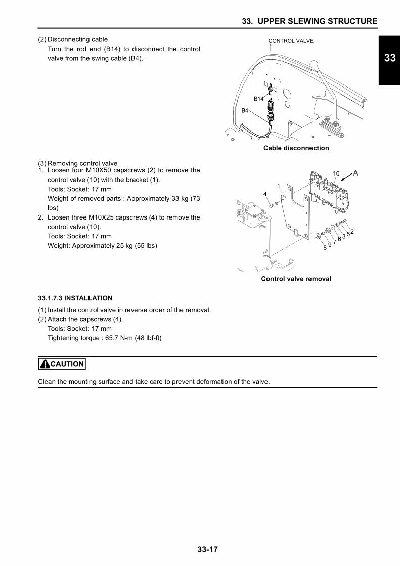
(3) Removing control valve
33.1.7.3 INSTALLATION(1) Install the control valve in reverse order of the removal.(2) Attach the capscrews (4).
Tools: Socket: 17 mmTightening torque : 65.7 N-m (48 lbf-ft)
Clean the mounting surface and take care to prevent deformation of the valve.
(2) Disconnecting cableTurn the rod end (B14) to disconnect the controlvalve from the swing cable (B4).
Cable disconnection
1. Loosen four M10X50 capscrews (2) to remove thecontrol valve (10) with the bracket (1).Tools: Socket: 17 mmWeight of removed parts : Approximately 33 kg (73lbs)
2. Loosen three M10X25 capscrews (4) to remove thecontrol valve (10).Tools: Socket: 17 mmWeight: Approximately 25 kg (55 lbs)
Control valve removal
CONTROL VALVE
B14
B4
A
8 9 7 6 3 52
1
10
4
33. UPPER SLEWING STRUCTURE
33-18
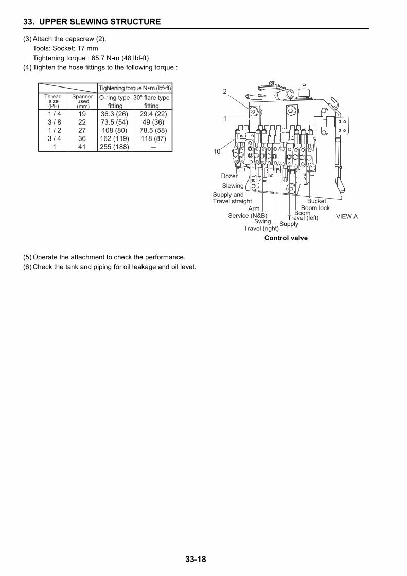
(3) Attach the capscrew (2).Tools: Socket: 17 mmTightening torque : 65.7 N-m (48 lbf-ft)
(4) Tighten the hose fittings to the following torque :
(5) Operate the attachment to check the performance.(6) Check the tank and piping for oil leakage and oil level.
Control valve
Thread size
(PF)
Spanner used(mm)
O-ring type fitting
flare type fitting
36.3 (26)73.5 (54)108 (80)162 (119)255 (188)
29.4 (22)49 (36)
78.5 (58)118 (87)
1922273641
1 / 43 / 81 / 23 / 4
1
Tightening torque N m (lbf ft)
VIEW A
2
1
10
Dozer
SlewingSupply andTravel straight
ArmService (N&B)
SwingTravel (right)
BucketBoom lock
BoomTravel (left)
Supply
33. UPPER SLEWING STRUCTURE
33-19
33
33.1.8 SOLENOID VALVE
33.1.8.1 REMOVAL PREPARATION(1) Unlock and open the right upper cover (1).(2) Remove the right lower cover (4) [See Section 33.1.2.1-(3)].
33.1.8.2 REMOVAL
33.1.8.3 INSTALLATION(1) Install the solenoid valve in reverse order of the removal.
Tighten the fittings at the following torque:
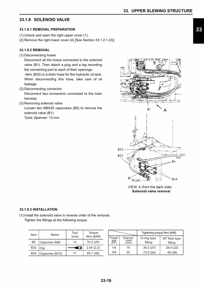
(1) Disconnecting hosesDisconnect all the hoses connected to the solenoidvalve (B1). Then attach a plug and a tag recordingthe connecting port to each of their openings.-Item (B32) is a drain hose for the hydraulic oil tank.When disconnecting this hose, take care of oilleakage.
(2) Disconnecting connectorDisconnect two connectors connected to the mainharness.
(3) Removing solenoid valveLoosen two M8X20 capscrews (B5) to remove thesolenoid valve (B1).Tools: Spanner: 13 mm
Solenoid valve removal
TorqueN m (lbf ft)
33.3 (25)
2.94 (2.2)
Tool (mm)
13Capscrew (M8)
Clip
B5
B33
65.7 (48)17Capscrew (M10)B34
Item Name
19
22
1/4
3/8
Tightening torque N m (lbf ft)
Thread size
(PF)
Spanner used(mm)
O-ring type fitting
flare type fitting
36.3 (27)
73.5 (54)
29.4 (22)
49 (36)
33. UPPER SLEWING STRUCTURE
33-20
33.1.9 MULTI-CONTROL VALVE
33.1.9.1 REMOVAL PREPARATION(1) Unlock and open the right upper cover (1).(2) Remove the right lower cover (4). [See Section 33.1.2.1-(3)](3) Release the residual pressure in the piping and hydraulic oil tank.
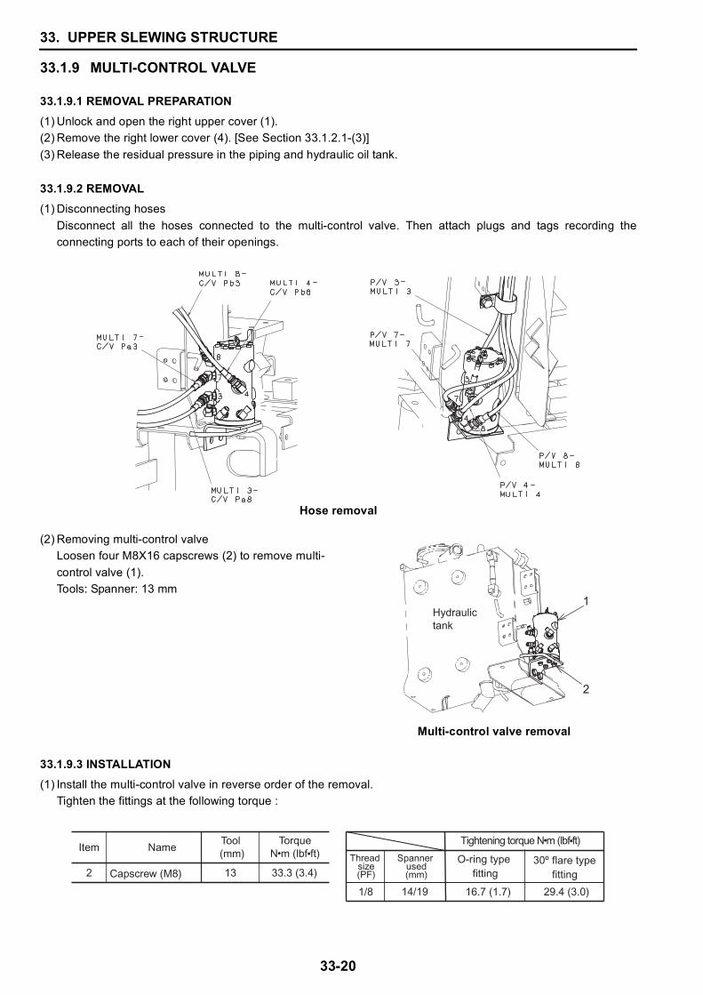
33.1.9.2 REMOVAL(1) Disconnecting hoses
Disconnect all the hoses connected to the multi-control valve. Then attach plugs and tags recording theconnecting ports to each of their openings.
Hose removal
33.1.9.3 INSTALLATION(1) Install the multi-control valve in reverse order of the removal.
Tighten the fittings at the following torque :
(2) Removing multi-control valveLoosen four M8X16 capscrews (2) to remove multi-control valve (1).Tools: Spanner: 13 mm
Multi-control valve removal
2
1Hydraulictank
TorqueN m (lbf ft)
33.3 (3.4)
Tool (mm)
13Capscrew (M8)2
Item Name
14/191/8
Tightening torque N m (lbf ft)
Thread size
(PF)
Spanner used(mm)
O-ring type fitting
flare type fitting
16.7 (1.7) 29.4 (3.0)
33. UPPER SLEWING STRUCTURE
33-21
33
33.1.10 FUEL TANK
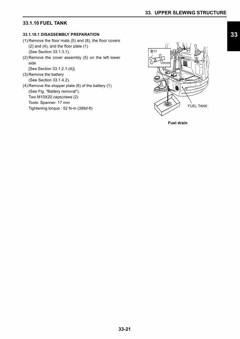
33.1.10.1 DISASSEMBLY PREPARATION(1) Remove the floor mats (5) and (8), the floor covers
(2) and (4), and the floor plate (1) (See Section 33.1.3.1).
(2) Remove the cover assembly (5) on the left lowerside[See Section 33.1.2.1-(4)].
(3) Remove the battery(See Section 33.1.4.2).
(4) Remove the stopper plate (6) of the battery (1) (See Fig. "Battery removal").Two M10X20 capscrews (2)Tools: Spanner: 17 mmTightening torque : 52 N-m (38lbf-ft)
Fuel drain
33. UPPER SLEWING STRUCTURE
33-22
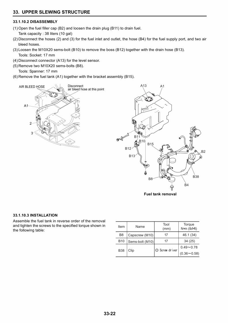
33.1.10.2 DISASSEMBLY(1) Open the fuel filler cap (B2) and loosen the drain plug (B11) to drain fuel.
Tank capacity : 38 liters (10 gal)(2) Disconnect the hoses (2) and (3) for the fuel inlet and outlet, the hose (B4) for the fuel supply port, and two air
bleed hoses.(3) Loosen the M10X20 sems-bolt (B10) to remove the boss (B12) together with the drain hose (B13).
Tools: Socket: 17 mm(4) Disconnect connector (A13) for the level sensor.(5) Remove two M10X20 sems-bolts (B8).
Tools: Spanner: 17 mm(6) Remove the fuel tank (A1) together with the bracket assembly (B15).
33.1.10.3 INSTALLATION
Fuel tank removal
Assemble the fuel tank in reverse order of the removaland tighten the screws to the specified torque shown inthe following table:
2
3
A1
Disconnect air bleed hose at this point
AIR BLEED HOSE
B2
A13 A1
B11
B12
B13
B10B15
B8
B4
B38
TorqueN m (lbf ft)
46.1 (34)
34 (25)
0.49 0.78
(0.36 0.58)
Capscrew (M10)
Sems-bolt (M10)
B8
B10
Item NameTool (mm)
17
17
B38 Clip
33. UPPER SLEWING STRUCTURE
33-23
33
33.1.11 HYDRAULIC OIL TANK
33.1.11.1 DISASSEMBLY PREPARATION
Press and hold the boot until air-relieving sound stops.
(7) Remove the control valve (See Section 33.1.7.2).(8) Remove the solenoid valve (See Section 33.1.8.2).(9) In addition, remove the harness and hose clamped on the tank.
-Remove the multi-control valve (option) if it is equipped.
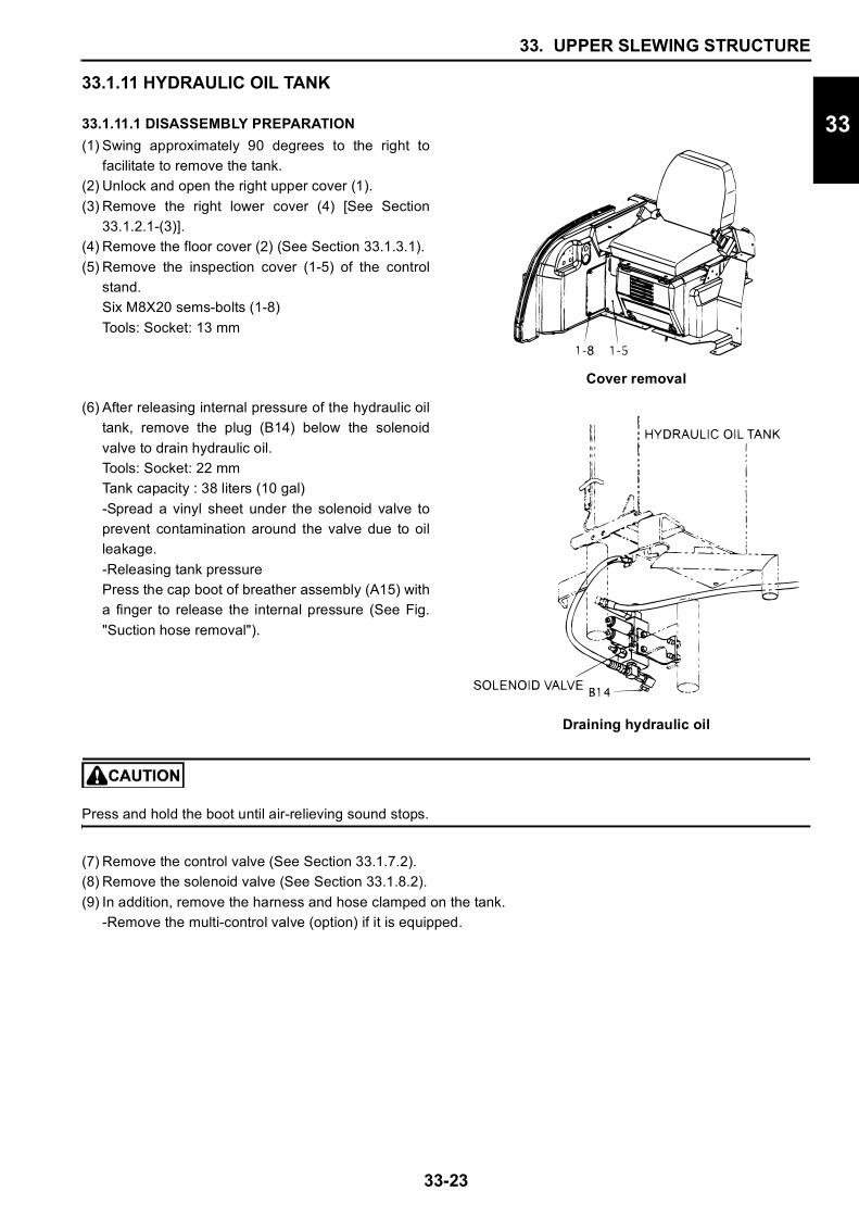
(1) Swing approximately 90 degrees to the right tofacilitate to remove the tank.
(2) Unlock and open the right upper cover (1).(3) Remove the right lower cover (4) [See Section
33.1.2.1-(3)].(4) Remove the floor cover (2) (See Section 33.1.3.1).(5) Remove the inspection cover (1-5) of the control
stand.Six M8X20 sems-bolts (1-8)Tools: Socket: 13 mm
Cover removal
(6) After releasing internal pressure of the hydraulic oiltank, remove the plug (B14) below the solenoidvalve to drain hydraulic oil.Tools: Socket: 22 mmTank capacity : 38 liters (10 gal)-Spread a vinyl sheet under the solenoid valve toprevent contamination around the valve due to oilleakage.-Releasing tank pressurePress the cap boot of breather assembly (A15) witha finger to release the internal pressure (See Fig."Suction hose removal").
Draining hydraulic oil


![Pillar and wall-mounted slewing jib cranes · Max. load capacity [kg] Electric slewing Pillar-mounted slewing jib cranes Wall-mounted slewing jib cranes Jib type/design Max. outreach](https://img.pdfslide.net/doc/110x75/5b535fa87f8b9ae30b8be93d/pillar-and-wall-mounted-slewing-jib-cranes-max-load-capacity-kg-electric.jpg)