Embed Size (px)
Citation preview
7/31/2019 3320 Digital Transm Over Fad Ch
http://slidepdf.com/reader/full/3320-digital-transm-over-fad-ch 1/51
Digital transmissionover a fading channel
• Narrowband system (introduction)
• BER vs. SNR in a narrowband system
• Wideband TDMA (introduction)
• Wideband DS-CDMA (introduction)
• Rake receiver (structure & analysis)
• Diversity techniques
7/31/2019 3320 Digital Transm Over Fad Ch
http://slidepdf.com/reader/full/3320-digital-transm-over-fad-ch 2/51
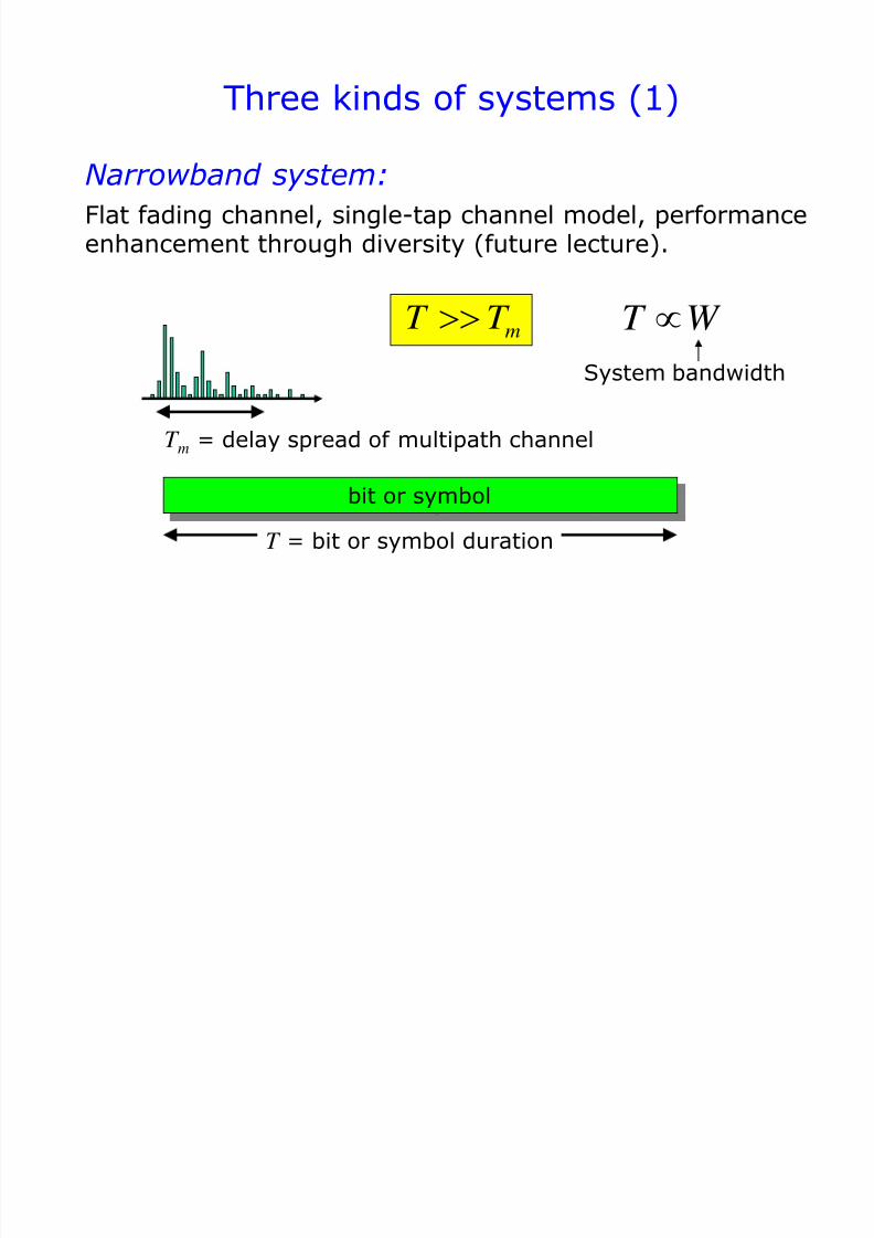
Three kinds of systems (1)
mT T
Narrowband system:
Flat fading channel, single-tap channel model, performanceenhancement through diversity (future lecture).
bit or symbol
T m = delay spread of multipath channel
T = bit or symbol duration
System bandwidth
T W
7/31/2019 3320 Digital Transm Over Fad Ch
http://slidepdf.com/reader/full/3320-digital-transm-over-fad-ch 3/51
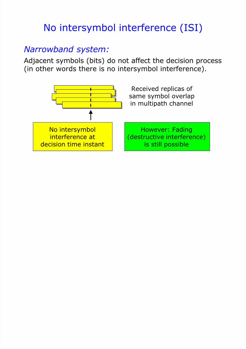
No intersymbol interference (ISI)
Adjacent symbols (bits) do not affect the decision process(in other words there is no intersymbol interference).
However: Fading(destructive interference)
is still possible
No intersymbolinterference at
decision time instant
Received replicas of same symbol overlapin multipath channel
Narrowband system:
7/31/2019 3320 Digital Transm Over Fad Ch
http://slidepdf.com/reader/full/3320-digital-transm-over-fad-ch 4/51
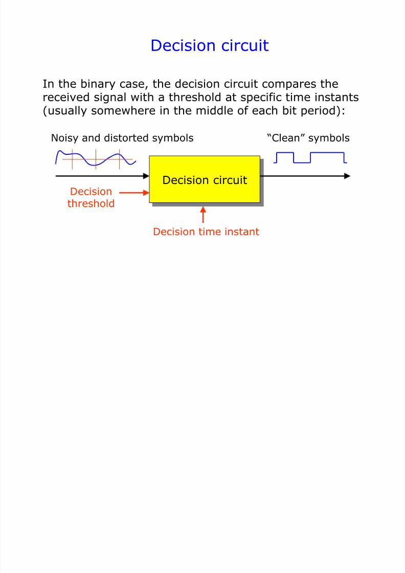
Decision circuit
In the binary case, the decision circuit compares thereceived signal with a threshold at specific time instants(usually somewhere in the middle of each bit period):
Decision time instant
Decision circuitDecisionthreshold
Noisy and distorted symbols “Clean” symbols
7/31/2019 3320 Digital Transm Over Fad Ch
http://slidepdf.com/reader/full/3320-digital-transm-over-fad-ch 5/51
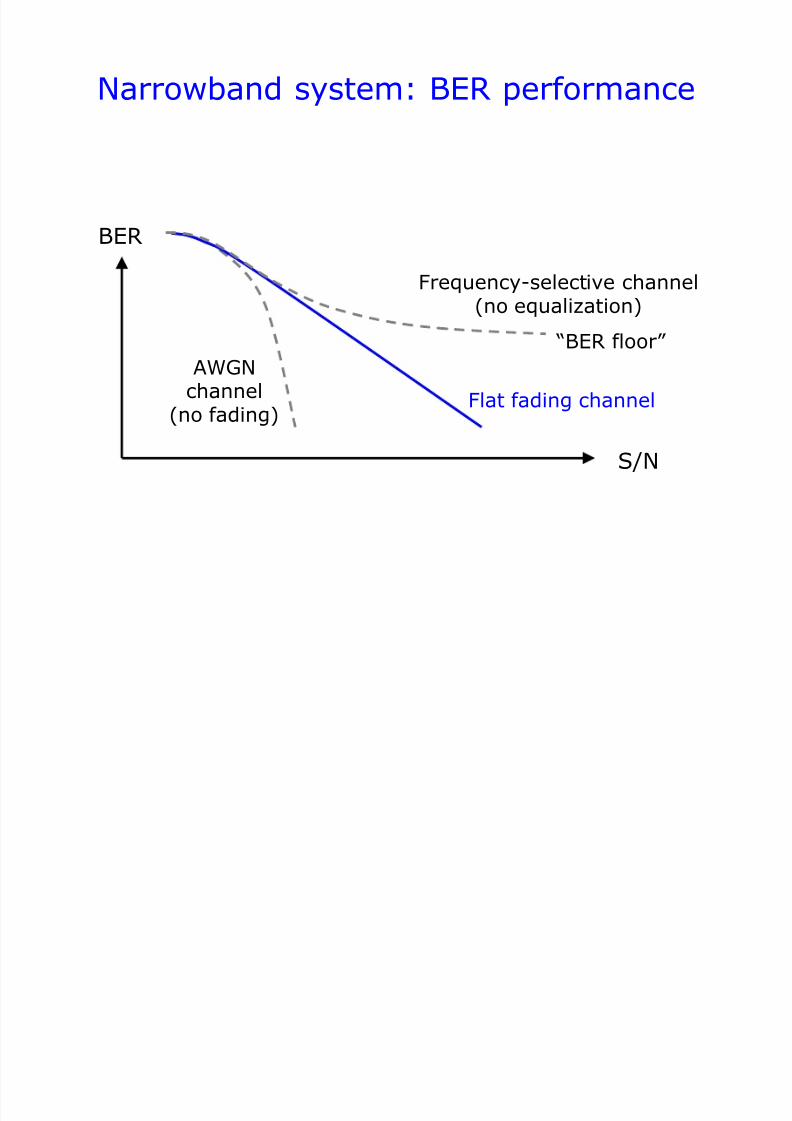
Narrowband system: BER performance
S/N
BER
Frequency-selective channel(no equalization)
Flat fading channel
AWGNchannel
(no fading)
“BER floor”
7/31/2019 3320 Digital Transm Over Fad Ch
http://slidepdf.com/reader/full/3320-digital-transm-over-fad-ch 6/51
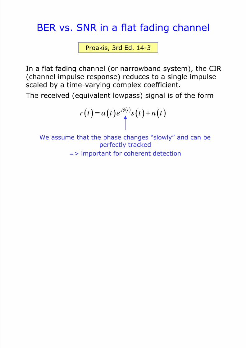
BER vs. SNR in a flat fading channel
In a flat fading channel (or narrowband system), the CIR(channel impulse response) reduces to a single impulse
scaled by a time-varying complex coefficient.The received (equivalent lowpass) signal is of the form
Proakis, 3rd Ed. 14-3
j t r t a t e s t n t
We assume that the phase changes “slowly” and can beperfectly tracked
=> important for coherent detection
7/31/2019 3320 Digital Transm Over Fad Ch
http://slidepdf.com/reader/full/3320-digital-transm-over-fad-ch 7/51
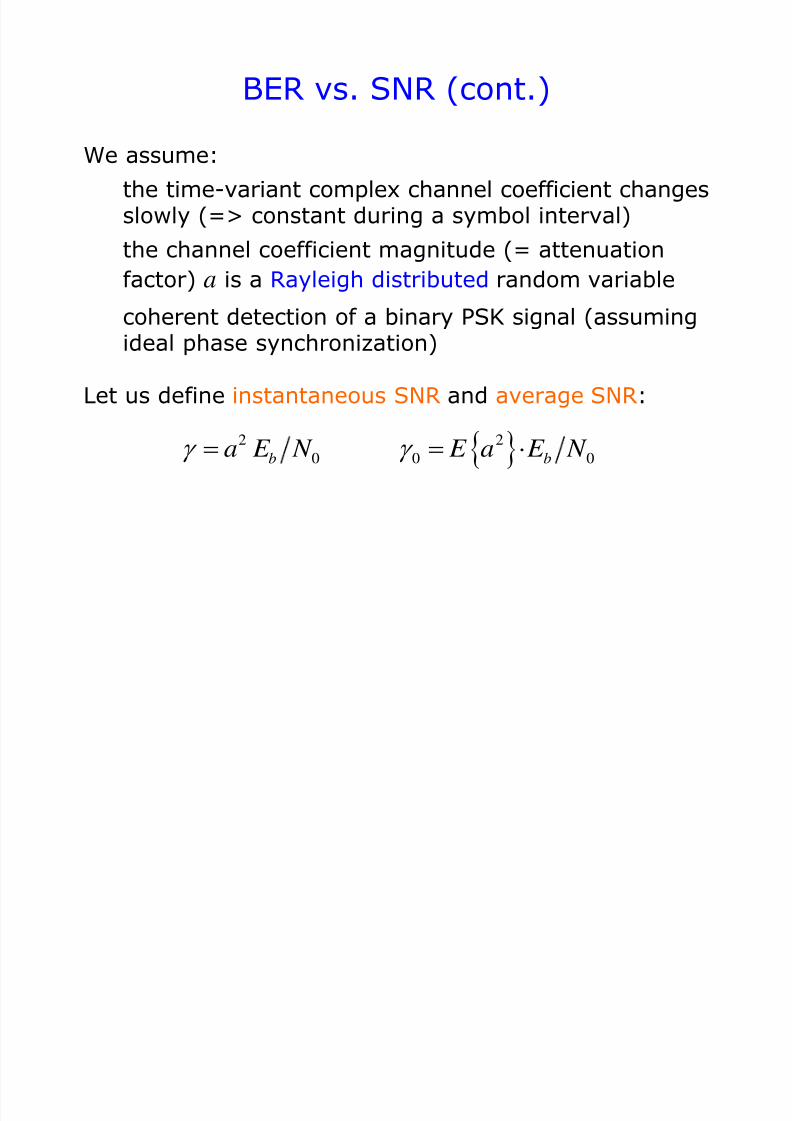
BER vs. SNR (cont.)
We assume:
the time-variant complex channel coefficient changesslowly (=> constant during a symbol interval)
the channel coefficient magnitude (= attenuation
factor) a is a Rayleigh distributed random variable
coherent detection of a binary PSK signal (assumingideal phase synchronization)
Let us define instantaneous SNR and average SNR:
2 2
0 0 0b ba E N E a E N
7/31/2019 3320 Digital Transm Over Fad Ch
http://slidepdf.com/reader/full/3320-digital-transm-over-fad-ch 8/51
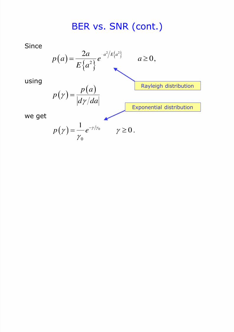
BER vs. SNR (cont.)
Since
using
we get
2 2
2
20,
a E aa p a e a
E a
p a
pd da
0
0
10 . p e
Rayleigh distribution
Exponential distribution
7/31/2019 3320 Digital Transm Over Fad Ch
http://slidepdf.com/reader/full/3320-digital-transm-over-fad-ch 9/51
BER vs. SNR (cont.)
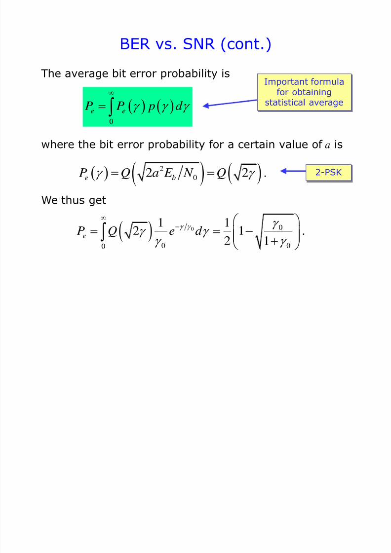
The average bit error probability is
where the bit error probability for a certain value of a is
We thus get
Important formulafor obtaining
statistical average 0
e eP P p d
2
02 2 .e bP Q a E N Q
0 0
0 00
1 12 1 .
2 1eP Q e d
2-PSK

7/31/2019 3320 Digital Transm Over Fad Ch
http://slidepdf.com/reader/full/3320-digital-transm-over-fad-ch 10/51
BER vs. SNR (cont.)
Approximation for large values of average SNR is obtainedin the following way. First, we write
0
0 0
1 1 11 1 1
2 1 2 1e
P
Then, we use
which leads to
1 1 2 x x
0 01 4 .
eP for large
7/31/2019 3320 Digital Transm Over Fad Ch
http://slidepdf.com/reader/full/3320-digital-transm-over-fad-ch 11/51
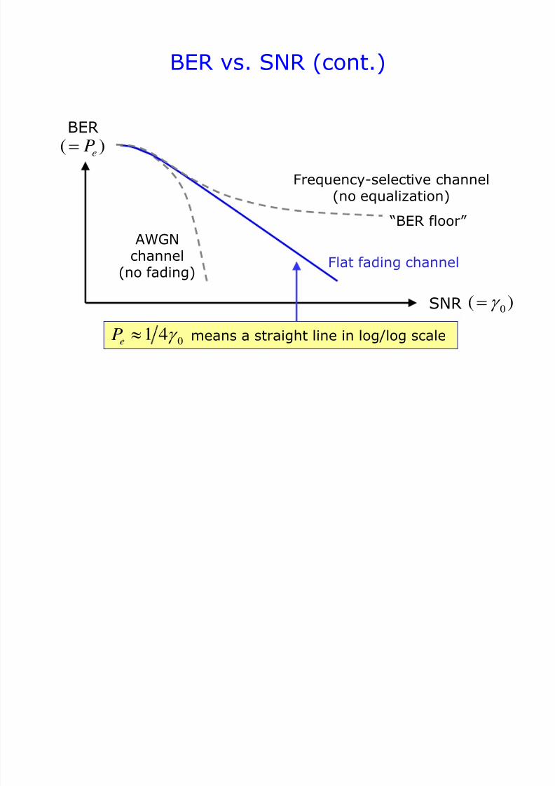
SNR
BER
Frequency-selective channel
(no equalization)
Flat fading channel
AWGNchannel
(no fading)
“BER floor”
BER vs. SNR (cont.)
01 4eP
( )eP
means a straight line in log/log scale
0( )
7/31/2019 3320 Digital Transm Over Fad Ch
http://slidepdf.com/reader/full/3320-digital-transm-over-fad-ch 12/51
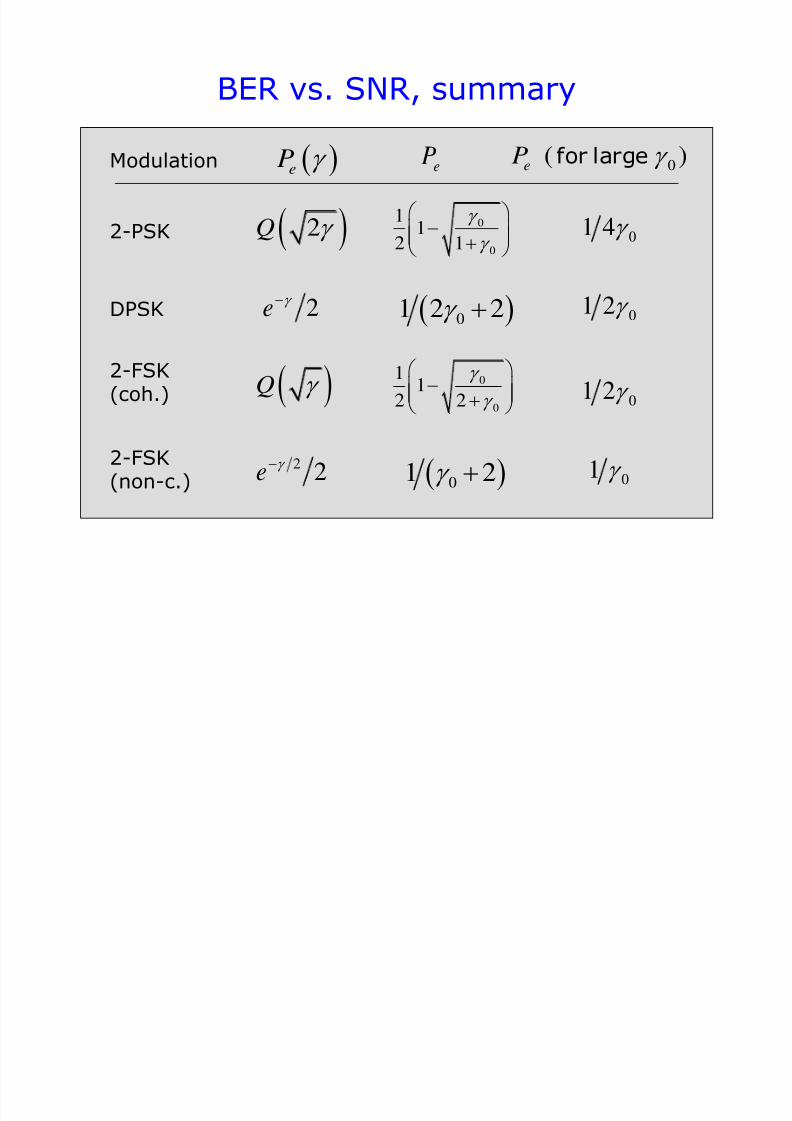
BER vs. SNR, summary
Modulation
2-PSK
DPSK
2-FSK(coh.)
2-FSK(non-c.)
eP eP 0
( )eP for large
2Q
2e
Q
22e
0
0
11
2 1
01 4
01 2
01 2
01
01 2 2
0
0
11
2 2
01 2
7/31/2019 3320 Digital Transm Over Fad Ch
http://slidepdf.com/reader/full/3320-digital-transm-over-fad-ch 13/51
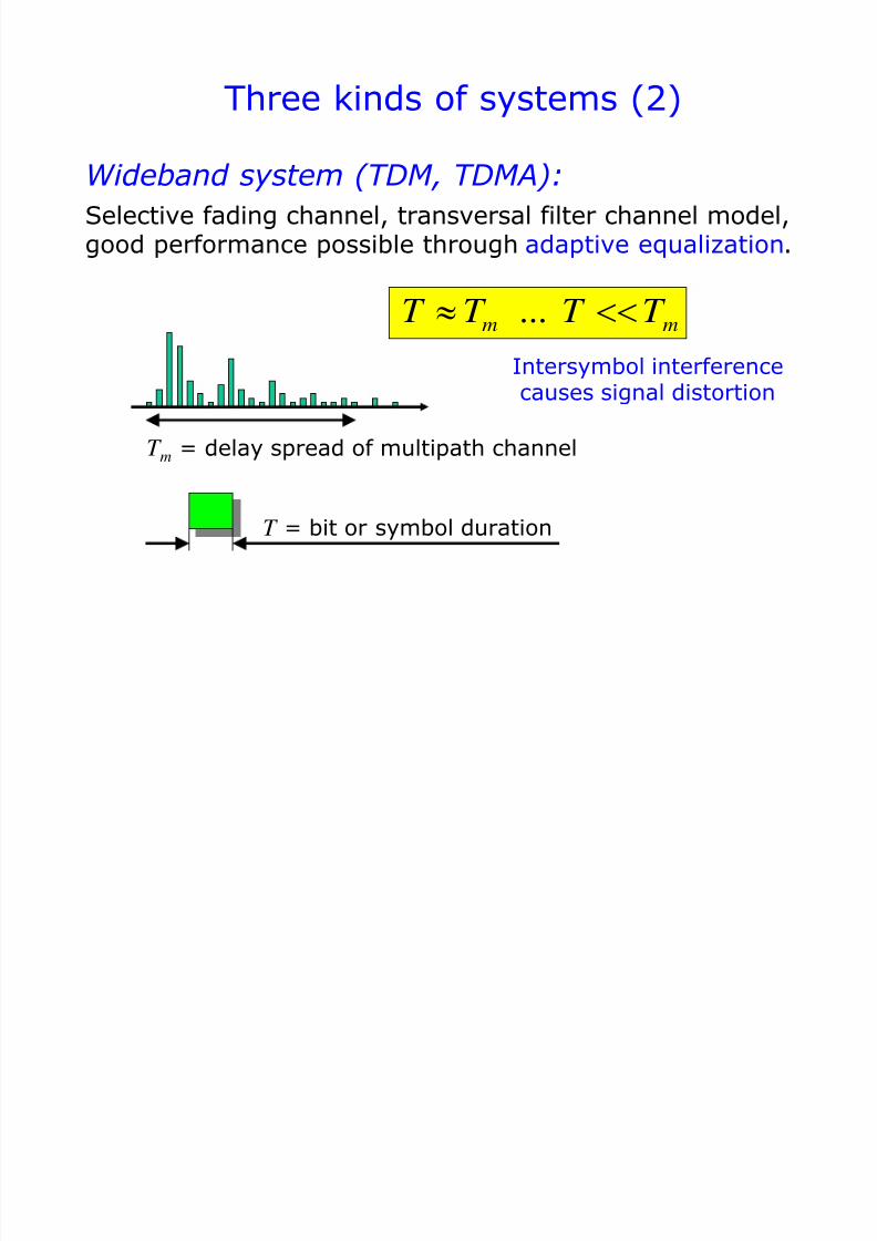
Three kinds of systems (2)
...m mT T T T
Wideband system (TDM, TDMA):
Selective fading channel, transversal filter channel model,good performance possible through adaptive equalization.
T = bit or symbol duration
Intersymbol interferencecauses signal distortion
T m= delay spread of multipath channel
7/31/2019 3320 Digital Transm Over Fad Ch
http://slidepdf.com/reader/full/3320-digital-transm-over-fad-ch 14/51
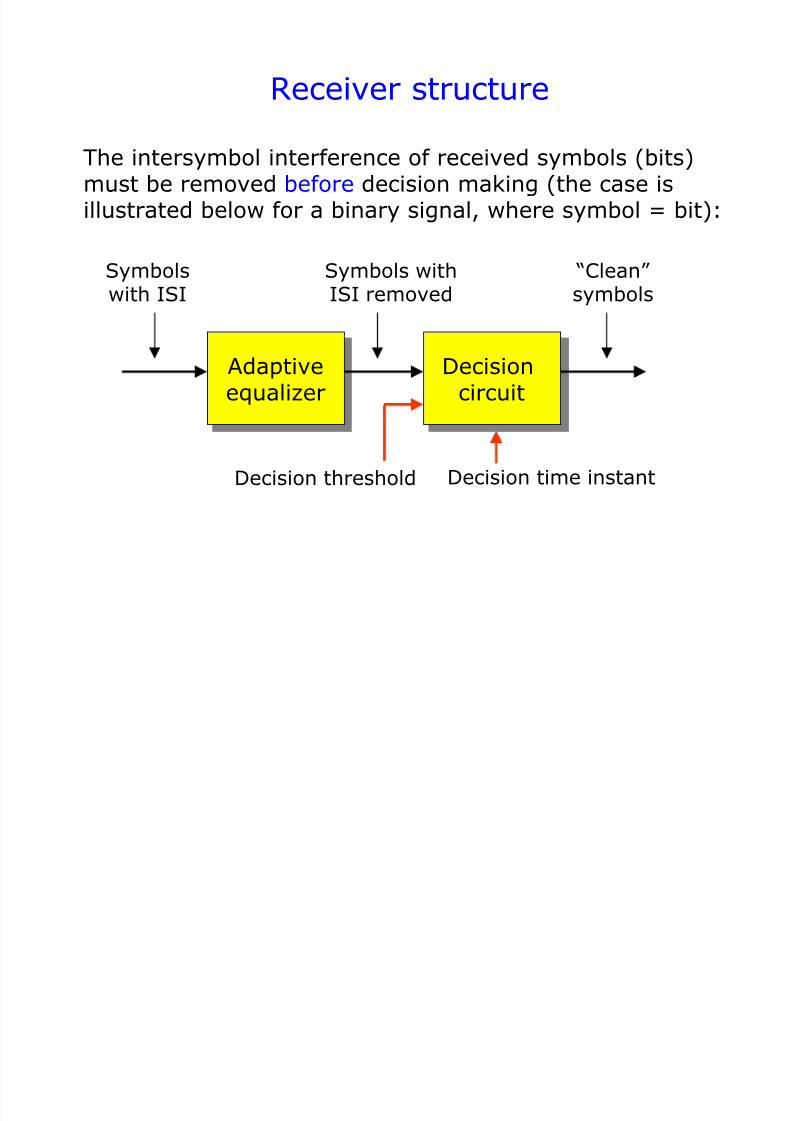
Receiver structure
The intersymbol interference of received symbols (bits)must be removed before decision making (the case isillustrated below for a binary signal, where symbol = bit):
Decisioncircuit
Adaptiveequalizer
Symbolswith ISI Symbols withISI removed “Clean” symbols
Decision time instantDecision threshold
7/31/2019 3320 Digital Transm Over Fad Ch
http://slidepdf.com/reader/full/3320-digital-transm-over-fad-ch 15/51
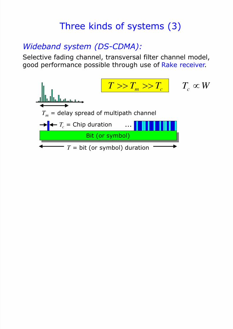
Three kinds of systems (3)
m cT T T
Wideband system (DS-CDMA):
Selective fading channel, transversal filter channel model,good performance possible through use of Rake receiver.
Bit (or symbol)
T m = delay spread of multipath channel
T = bit (or symbol) duration
T c = Chip duration ...
cT W
7/31/2019 3320 Digital Transm Over Fad Ch
http://slidepdf.com/reader/full/3320-digital-transm-over-fad-ch 16/51
Rake receiver structure and operation
Rake receiver <=> a signal processing example thatillustrates some important concepts
Rake receiver is used in DS-CDMA (Direct Sequence
Code Division Multiple Access) systemsRake “fingers” synchronize to signal components thatare received via a wideband multipath channel
Important task of Rake receiver is channel estimation
Output signals from Rake fingers are combined, forinstance using Maximum Ratio Combining (MRC)
7/31/2019 3320 Digital Transm Over Fad Ch
http://slidepdf.com/reader/full/3320-digital-transm-over-fad-ch 17/51
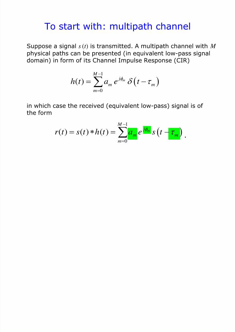
To start with: multipath channel
in which case the received (equivalent low-pass) signal is of the form
Suppose a signal s (t ) is transmitted. A multipath channel with M
physical paths can be presented (in equivalent low-pass signaldomain) in form of its Channel Impulse Response (CIR)
1
0
( ) ( ) ( ) m
M j
m m
m
r t s t h t a e s t
1
0( )
m
M j
m m
mh t a e t
.
7/31/2019 3320 Digital Transm Over Fad Ch
http://slidepdf.com/reader/full/3320-digital-transm-over-fad-ch 18/51
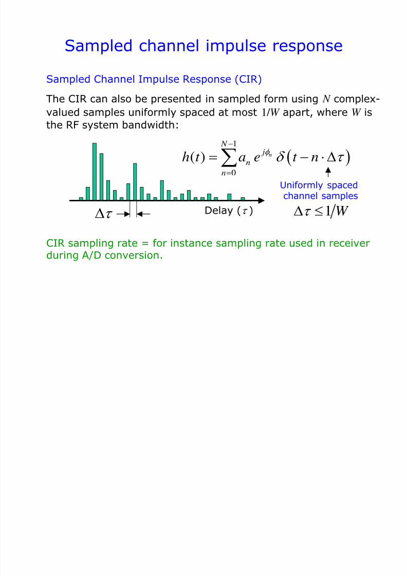
Sampled channel impulse response
Delay ( )
1
0
( ) n
N j
n
n
h t a e t n
Sampled Channel Impulse Response (CIR)
The CIR can also be presented in sampled form using N complex-
valued samples uniformly spaced at most 1/ W apart, where W is
the RF system bandwidth:
CIR sampling rate = for instance sampling rate used in receiverduring A/D conversion.
Uniformly spacedchannel samples
1 W
7/31/2019 3320 Digital Transm Over Fad Ch
http://slidepdf.com/reader/full/3320-digital-transm-over-fad-ch 19/51
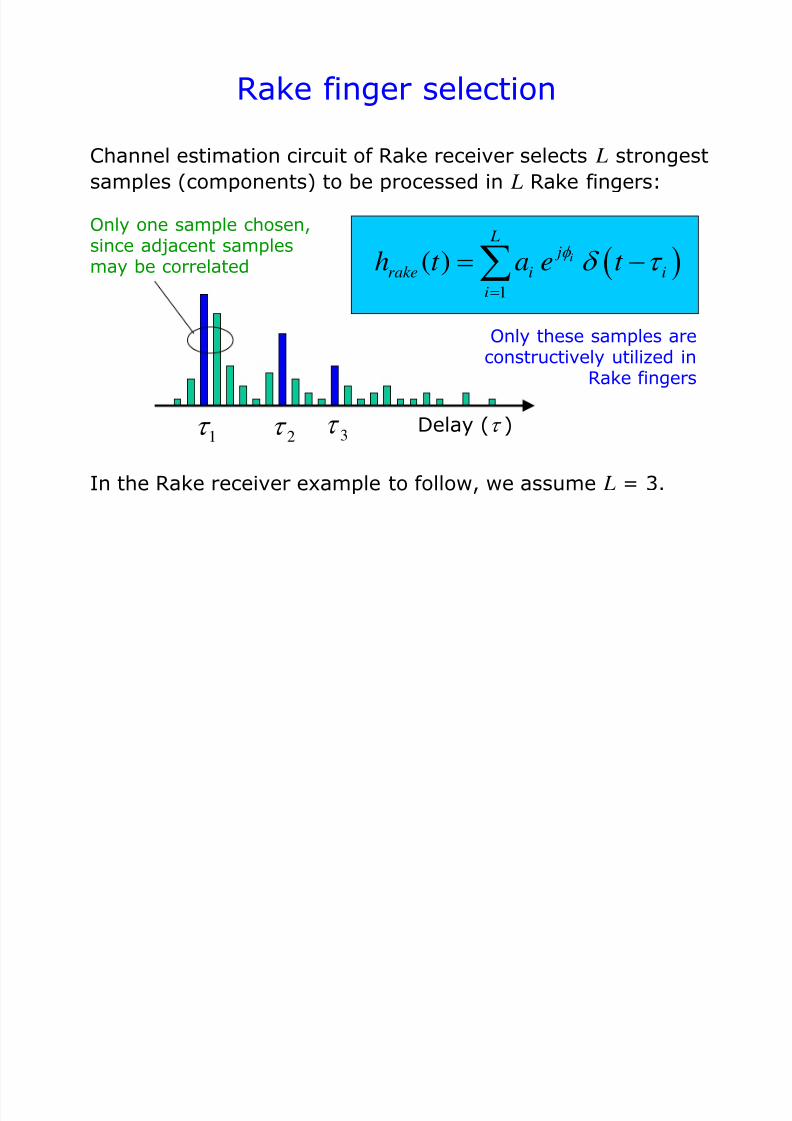
Rake finger selection
Delay ( )
1
( ) i
L j
rake i ii
h t a e t
Channel estimation circuit of Rake receiver selects L strongest
samples (components) to be processed in L Rake fingers:
In the Rake receiver example to follow, we assume L = 3.
1 2 3
Only one sample chosen,since adjacent samplesmay be correlated
Only these samples areconstructively utilized in
Rake fingers
7/31/2019 3320 Digital Transm Over Fad Ch
http://slidepdf.com/reader/full/3320-digital-transm-over-fad-ch 20/51
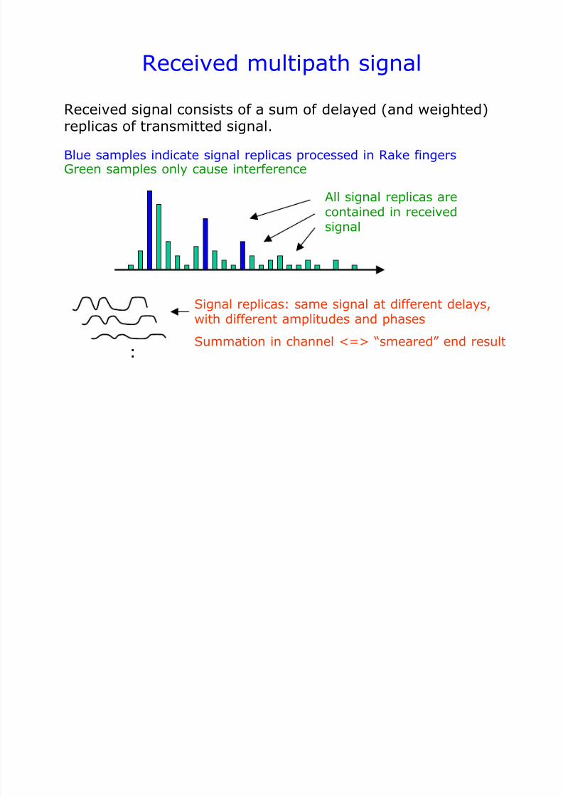
Received multipath signal
Received signal consists of a sum of delayed (and weighted)replicas of transmitted signal.
All signal replicas arecontained in receivedsignal
:
Signal replicas: same signal at different delays,with different amplitudes and phases
Summation in channel <=> “smeared” end result
Blue samples indicate signal replicas processed in Rake fingersGreen samples only cause interference
7/31/2019 3320 Digital Transm Over Fad Ch
http://slidepdf.com/reader/full/3320-digital-transm-over-fad-ch 21/51
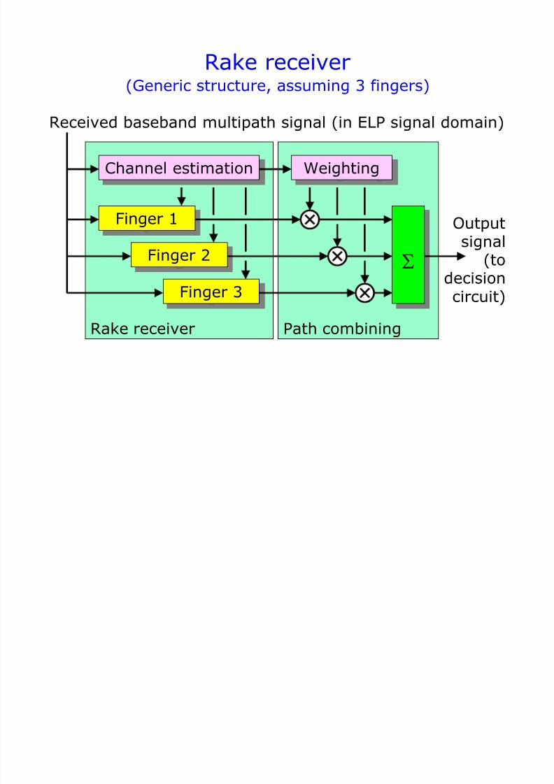
Rake receiver
Finger 1
Finger 2
Channel estimation
Received baseband multipath signal (in ELP signal domain)
Finger 3
Outputsignal
(todecision
circuit)
Rake receiver Path combining
(Generic structure, assuming 3 fingers)
Weighting
7/31/2019 3320 Digital Transm Over Fad Ch
http://slidepdf.com/reader/full/3320-digital-transm-over-fad-ch 22/51
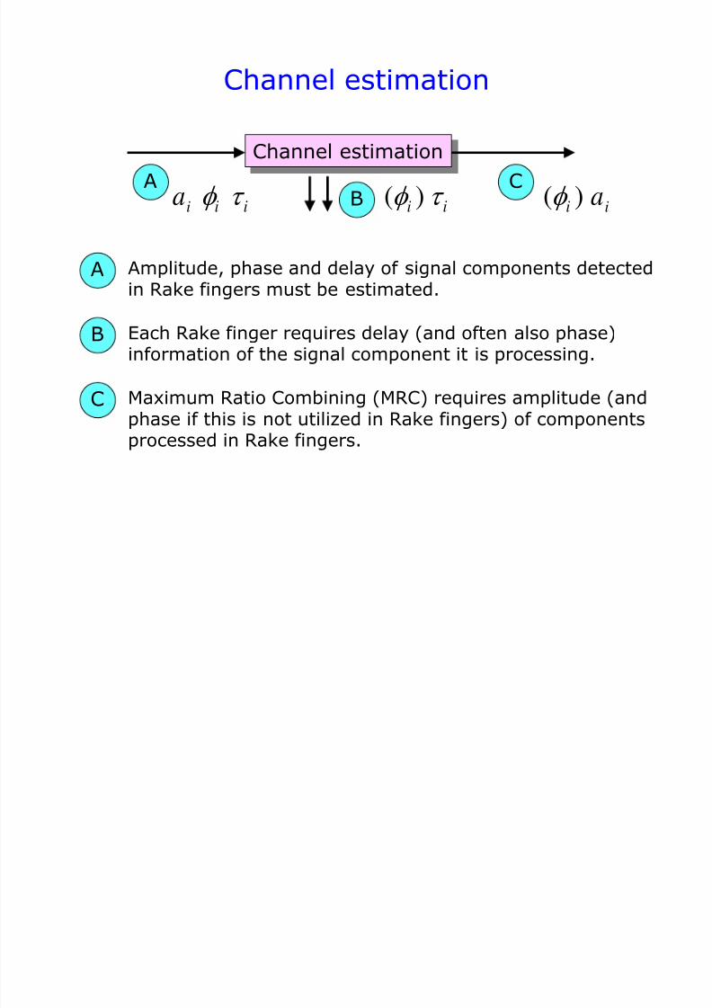
Channel estimation
Channel estimation
AB
C
A
B
C
Amplitude, phase and delay of signal components detectedin Rake fingers must be estimated.
ia
i
i
Each Rake finger requires delay (and often also phase)information of the signal component it is processing.
ia
i
Maximum Ratio Combining (MRC) requires amplitude (andphase if this is not utilized in Rake fingers) of componentsprocessed in Rake fingers.
( )i
( )i
7/31/2019 3320 Digital Transm Over Fad Ch
http://slidepdf.com/reader/full/3320-digital-transm-over-fad-ch 23/51
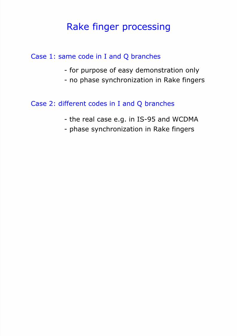
Rake finger processing
Case 1: same code in I and Q branches
Case 2: different codes in I and Q branches
- for purpose of easy demonstration only
- the real case e.g. in IS-95 and WCDMA
- no phase synchronization in Rake fingers
- phase synchronization in Rake fingers
7/31/2019 3320 Digital Transm Over Fad Ch
http://slidepdf.com/reader/full/3320-digital-transm-over-fad-ch 24/51
Delay
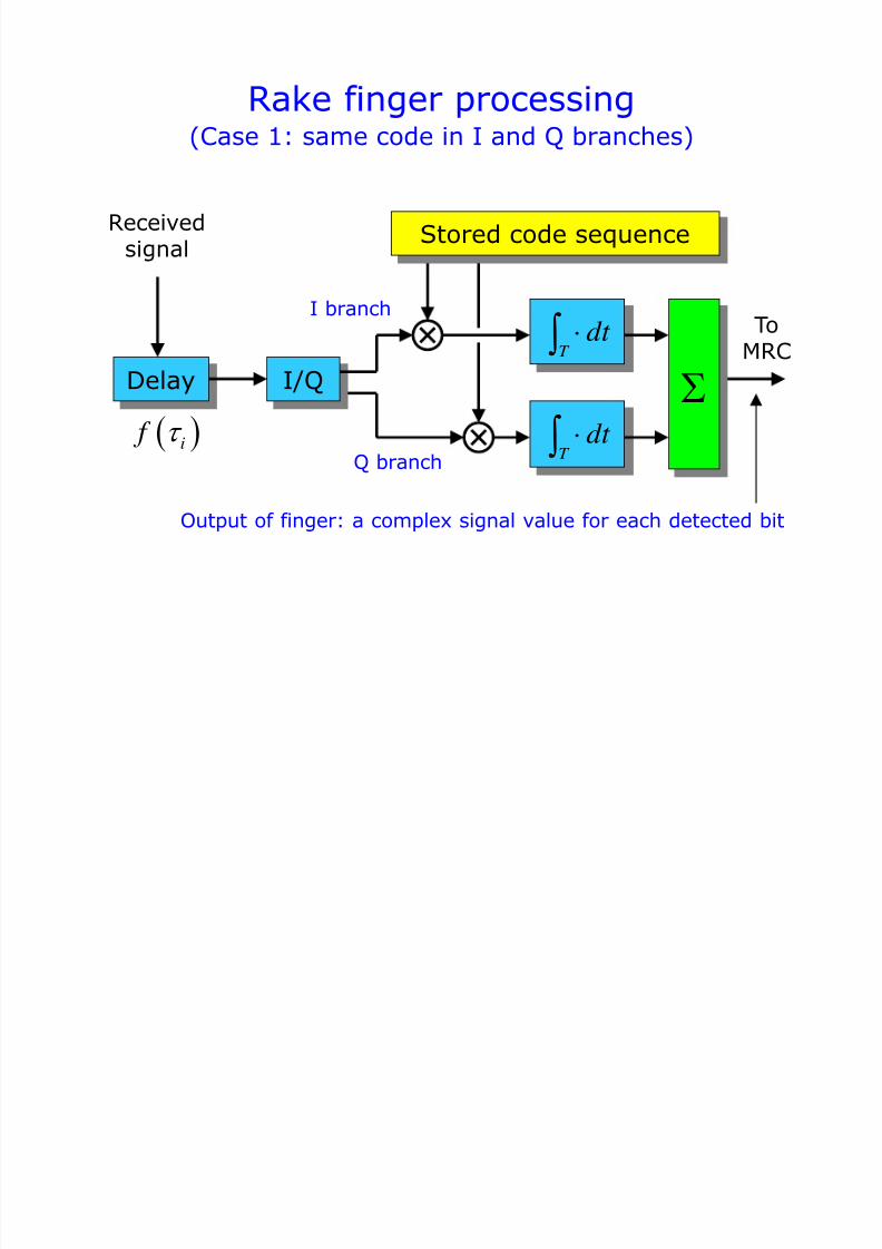
Rake finger processing
T dt
Receivedsignal
ToMRC
T dt i f
Stored code sequence
(Case 1: same code in I and Q branches)
I branch
Q branch
I/Q
Output of finger: a complex signal value for each detected bit
7/31/2019 3320 Digital Transm Over Fad Ch
http://slidepdf.com/reader/full/3320-digital-transm-over-fad-ch 25/51
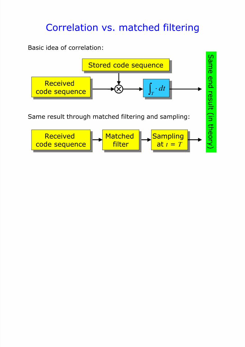
Correlation vs. matched filtering
T dt Receivedcode sequence
Stored code sequence
Basic idea of correlation:
Same result through matched filtering and sampling:
Receivedcode sequence
Matchedfilter
Samplingat t = T
S am e en d r e s ul t ( i n
t h e or y )
7/31/2019 3320 Digital Transm Over Fad Ch
http://slidepdf.com/reader/full/3320-digital-transm-over-fad-ch 26/51
Rake finger processing
1
i n N
j j
i i n n
nn i
r t z t v t w t
a e s t a e s t w t
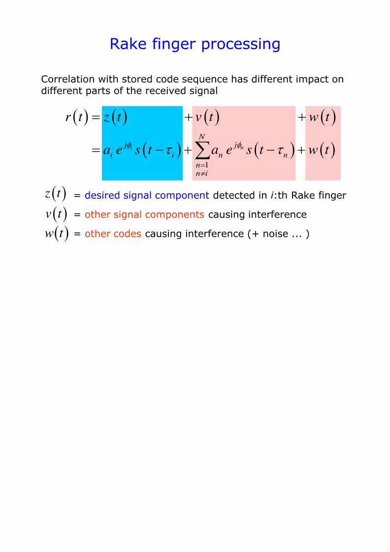
Correlation with stored code sequence has different impact ondifferent parts of the received signal
= desired signal component detected in i :th Rake finger
= other signal components causing interference
= other codes causing interference (+ noise ... )
z t
v t
w t
7/31/2019 3320 Digital Transm Over Fad Ch
http://slidepdf.com/reader/full/3320-digital-transm-over-fad-ch 27/51
Rake finger processing
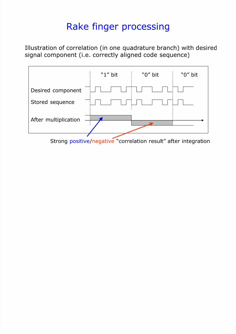
Illustration of correlation (in one quadrature branch) with desiredsignal component (i.e. correctly aligned code sequence)
Desired component
Stored sequence
After multiplication
Strong positive /negative “correlation result” after integration
“1” bit “0” bit “0” bit
7/31/2019 3320 Digital Transm Over Fad Ch
http://slidepdf.com/reader/full/3320-digital-transm-over-fad-ch 28/51
Rake finger processing
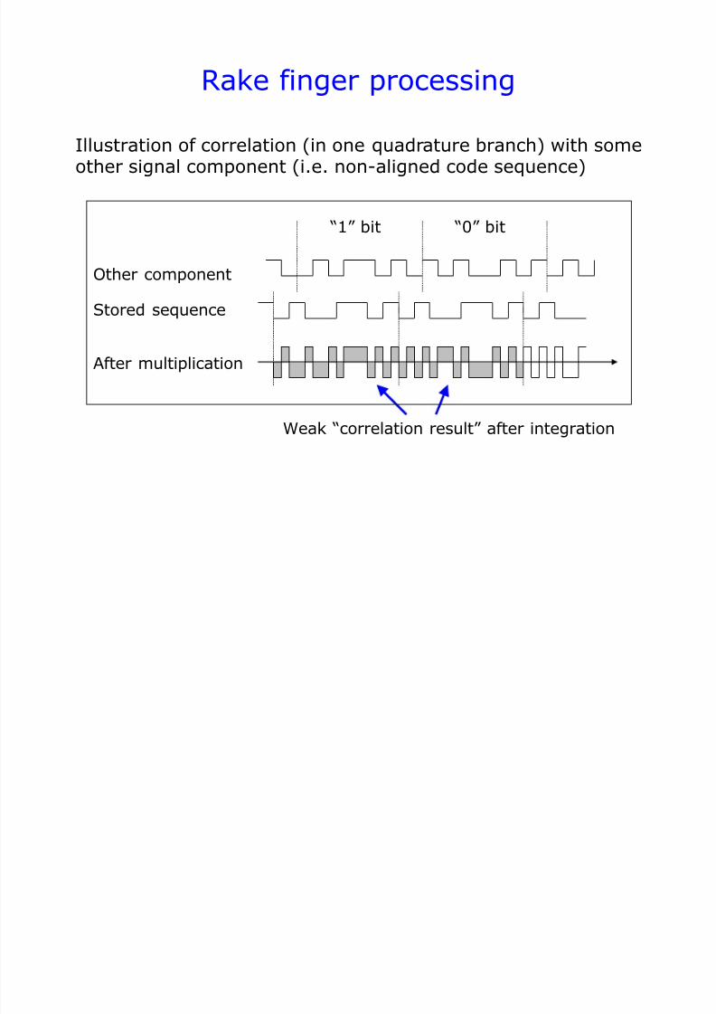
Illustration of correlation (in one quadrature branch) with someother signal component (i.e. non-aligned code sequence)
Other component
Stored sequence
After multiplication
Weak “correlation result” after integration
“1” bit “0” bit
7/31/2019 3320 Digital Transm Over Fad Ch
http://slidepdf.com/reader/full/3320-digital-transm-over-fad-ch 29/51
Rake finger processing
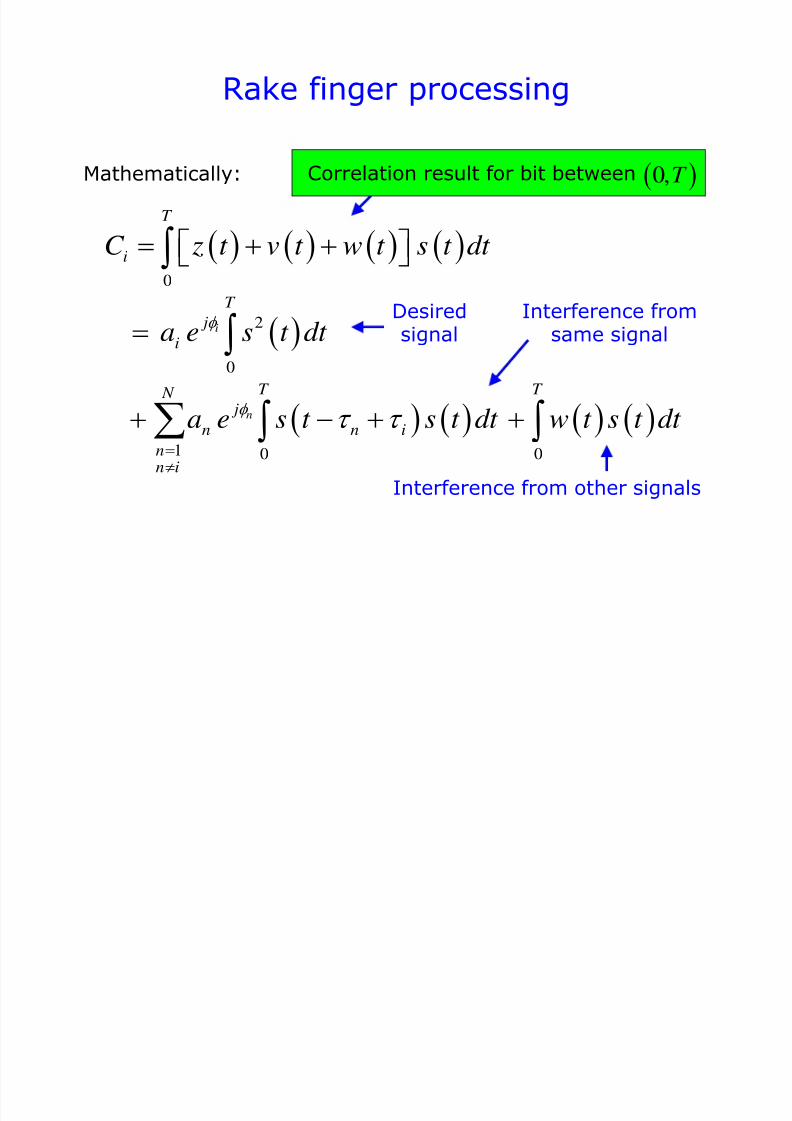
Mathematically:
0
2
0
1 0 0
i
n
T
i
T
j
i
T T N j
n n i
nn i
C z t v t w t s t dt
a e s t dt
a e s t s t dt w t s t dt
Correlation result for bit between
Interference fromsame signal
Interference from other signals
Desiredsignal
0,T
7/31/2019 3320 Digital Transm Over Fad Ch
http://slidepdf.com/reader/full/3320-digital-transm-over-fad-ch 30/51
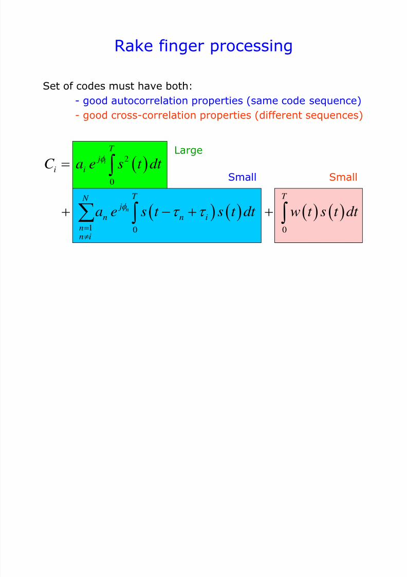
Rake finger processing
Set of codes must have both:
- good autocorrelation properties (same code sequence)
- good cross-correlation properties (different sequences)
2
0
1 0 0
i
n
T
j
i i
T T N j
n n inn i
C a e s t dt
a e s t s t dt w t s t dt
Large
Small Small
7/31/2019 3320 Digital Transm Over Fad Ch
http://slidepdf.com/reader/full/3320-digital-transm-over-fad-ch 31/51
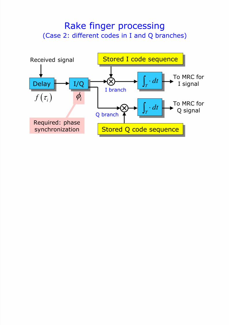
Delay
Rake finger processing
T dt
Received signal
T dt
Stored I code sequence
(Case 2: different codes in I and Q branches)
I branch
Q branch
I/Q
Stored Q code sequence
i
To MRC forI signal
To MRC forQ signal
Required: phasesynchronization
i f
7/31/2019 3320 Digital Transm Over Fad Ch
http://slidepdf.com/reader/full/3320-digital-transm-over-fad-ch 32/51
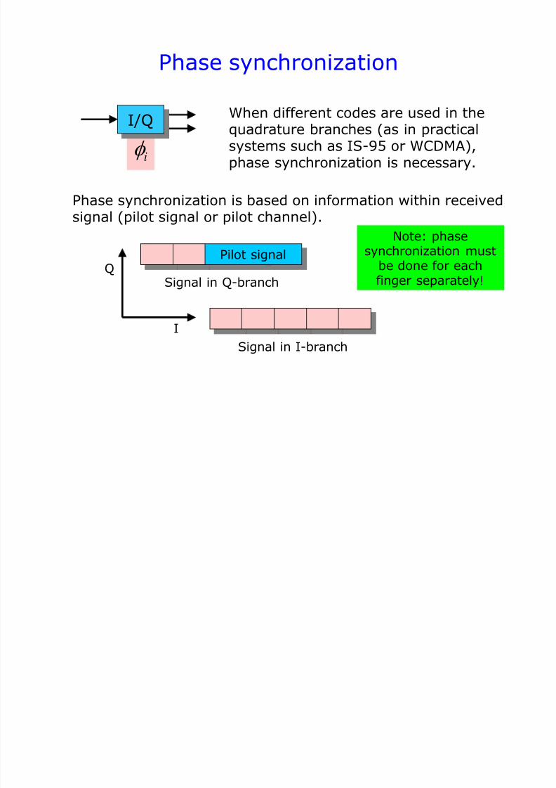
Phase synchronization
I/Q
i
When different codes are used in thequadrature branches (as in practicalsystems such as IS-95 or WCDMA),phase synchronization is necessary.
Phase synchronization is based on information within receivedsignal (pilot signal or pilot channel).
Signal in I-branch
Pilot signal
Signal in Q-branch
I
Q
Note: phasesynchronization must
be done for eachfinger separately!
7/31/2019 3320 Digital Transm Over Fad Ch
http://slidepdf.com/reader/full/3320-digital-transm-over-fad-ch 33/51
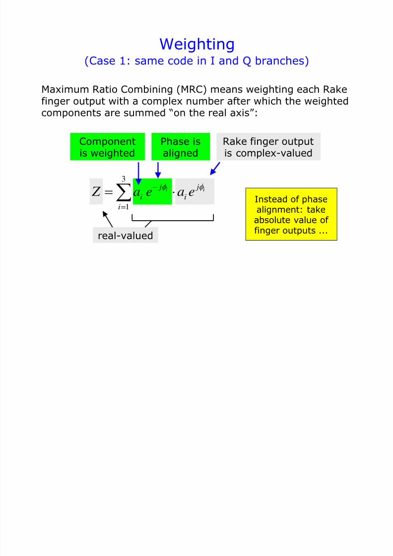
Weighting
Maximum Ratio Combining (MRC) means weighting each Rakefinger output with a complex number after which the weightedcomponents are summed “on the real axis”:
3
1
i i j j
i i
i
Z a e a e
Componentis weighted
Phase isaligned
Rake finger outputis complex-valued
real-valued
(Case 1: same code in I and Q branches)
Instead of phase
alignment: takeabsolute value of finger outputs ...
7/31/2019 3320 Digital Transm Over Fad Ch
http://slidepdf.com/reader/full/3320-digital-transm-over-fad-ch 34/51
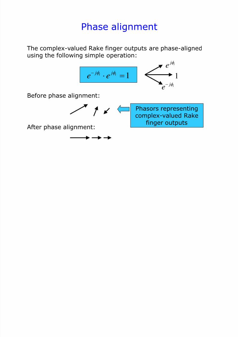
Phase alignment
The complex-valued Rake finger outputs are phase-alignedusing the following simple operation:
1i i j je e
Before phase alignment:
i je
i je
1
After phase alignment:
Phasors representingcomplex-valued Rake
finger outputs
7/31/2019 3320 Digital Transm Over Fad Ch
http://slidepdf.com/reader/full/3320-digital-transm-over-fad-ch 35/51
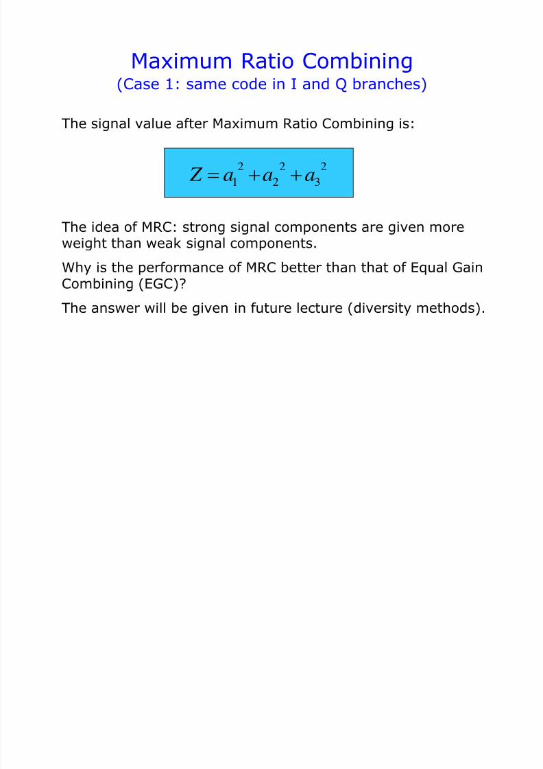
Maximum Ratio Combining
The idea of MRC: strong signal components are given moreweight than weak signal components.
Why is the performance of MRC better than that of Equal Gain
Combining (EGC)?The answer will be given in future lecture (diversity methods).
The signal value after Maximum Ratio Combining is:
2 2 2
1 2 3 Z a a a
(Case 1: same code in I and Q branches)
7/31/2019 3320 Digital Transm Over Fad Ch
http://slidepdf.com/reader/full/3320-digital-transm-over-fad-ch 36/51
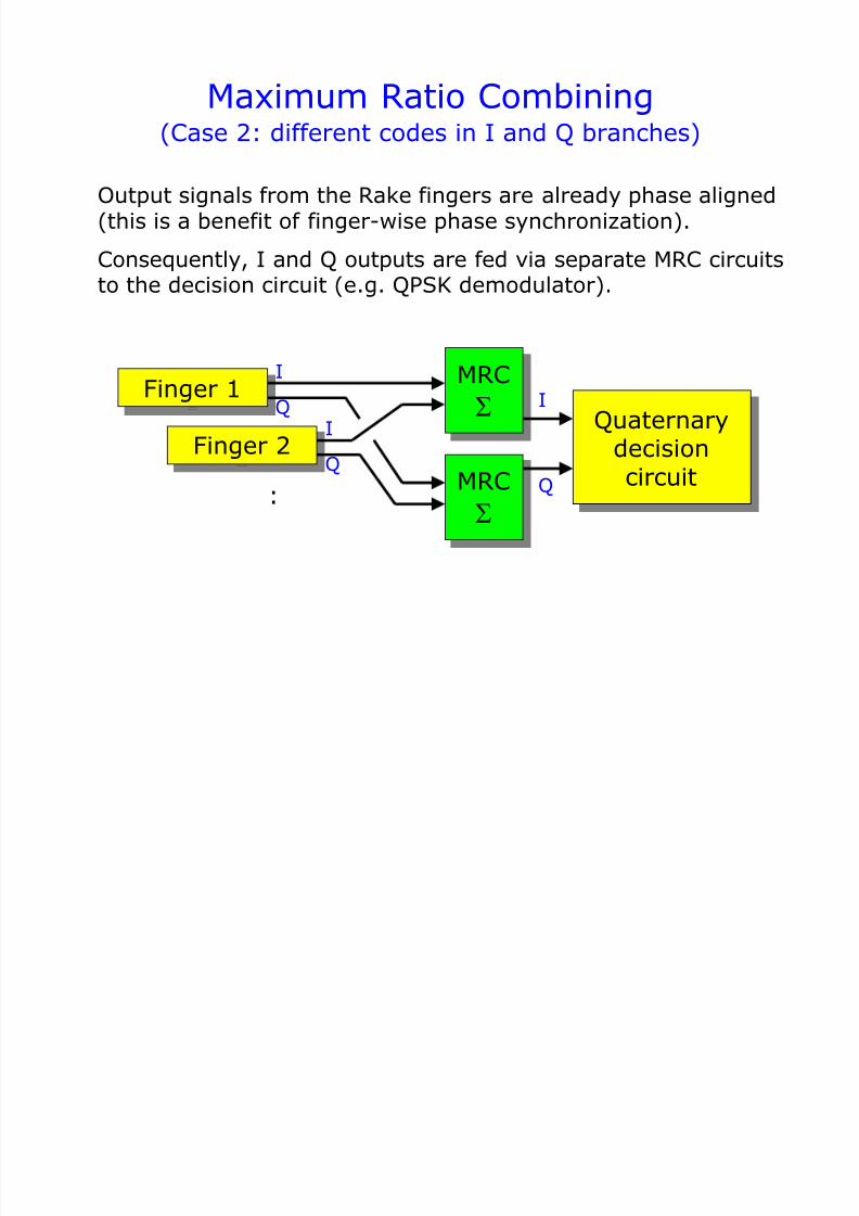
Maximum Ratio Combining
Output signals from the Rake fingers are already phase aligned(this is a benefit of finger-wise phase synchronization).
Consequently, I and Q outputs are fed via separate MRC circuitsto the decision circuit (e.g. QPSK demodulator).
(Case 2: different codes in I and Q branches)
Quaternary
decisioncircuit
Finger 1
Finger 2
MRC
MRC
:
I
Q
I
Q
I
Q
7/31/2019 3320 Digital Transm Over Fad Ch
http://slidepdf.com/reader/full/3320-digital-transm-over-fad-ch 37/51
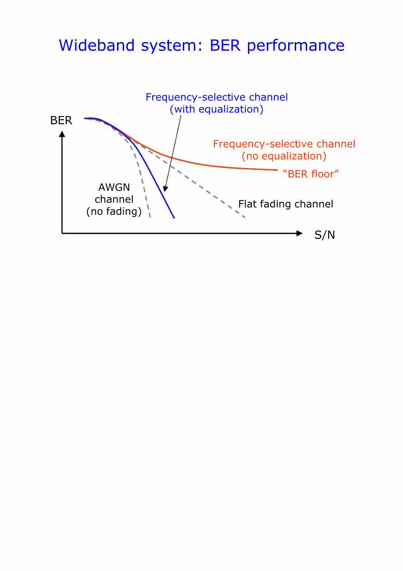
Wideband system: BER performance
S/N
BER
Frequency-selective channel(no equalization)
Flat fading channel
AWGNchannel
(no fading)
Frequency-selective channel(with equalization)
“BER floor”
7/31/2019 3320 Digital Transm Over Fad Ch
http://slidepdf.com/reader/full/3320-digital-transm-over-fad-ch 38/51
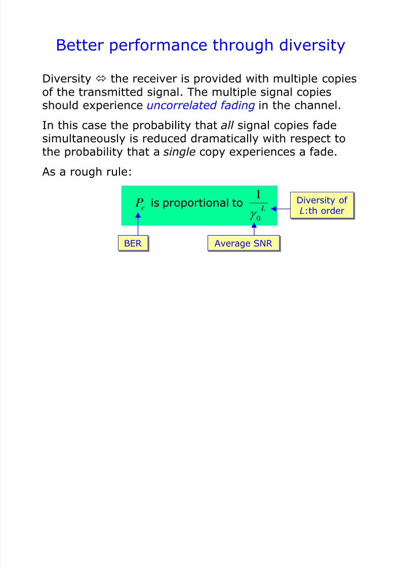
Better performance through diversity
Diversity the receiver is provided with multiple copiesof the transmitted signal. The multiple signal copiesshould experience uncorrelated fading in the channel.
In this case the probability that all signal copies fade
simultaneously is reduced dramatically with respect tothe probability that a single copy experiences a fade.
As a rough rule:
0
1e L
P
is proportional to
BER Average SNR
Diversity of
L:th order
7/31/2019 3320 Digital Transm Over Fad Ch
http://slidepdf.com/reader/full/3320-digital-transm-over-fad-ch 39/51
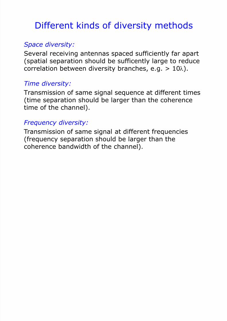
Different kinds of diversity methods
Space diversity:
Several receiving antennas spaced sufficiently far apart(spatial separation should be sufficently large to reducecorrelation between diversity branches, e.g. > 10l).
Time diversity:
Transmission of same signal sequence at different times(time separation should be larger than the coherencetime of the channel).
Frequency diversity:
Transmission of same signal at different frequencies(frequency separation should be larger than thecoherence bandwidth of the channel).

7/31/2019 3320 Digital Transm Over Fad Ch
http://slidepdf.com/reader/full/3320-digital-transm-over-fad-ch 40/51
Diversity methods (cont.)
Polarization diversity:
Only two diversity branches are available. Not widelyused.
Multipath diversity:
Signal replicas received at different delays(RAKE receiver in CDMA)
Signal replicas received via different angles of arrival (directional antennas at the receiver)
Equalization in a TDM/TDMA system providessimilar performance as multipath diversity.

7/31/2019 3320 Digital Transm Over Fad Ch
http://slidepdf.com/reader/full/3320-digital-transm-over-fad-ch 41/51
Selection diversity vs. signal combining
Selection diversity: Signal with best quality is selected.
Equal Gain Combining (EGC)
Signal copies are combined coherently:
Maximum Ratio Combining (MRC, best SNR is achieved)
Signal copies are weighted and combined coherently:
1 1
i i L L j j
EGC i i
i i
Z a e e a
2
1 1
i i
L L j j
MRC i i i
i i
Z a e a e a
7/31/2019 3320 Digital Transm Over Fad Ch
http://slidepdf.com/reader/full/3320-digital-transm-over-fad-ch 42/51
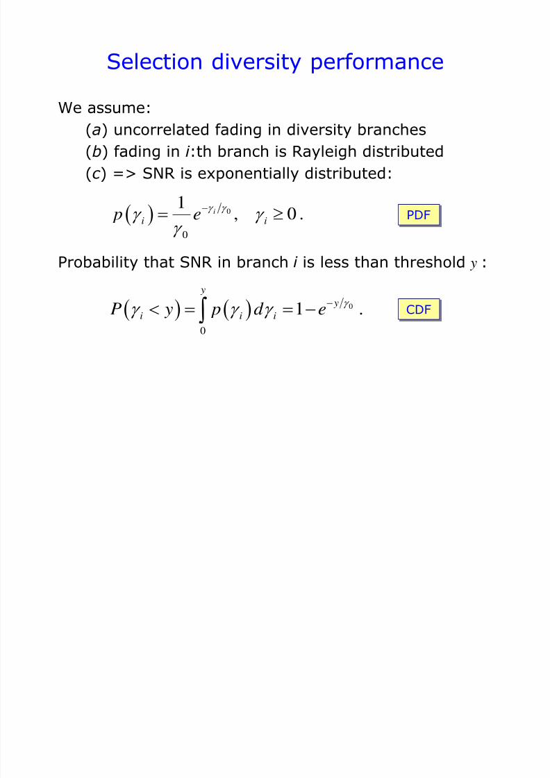
Selection diversity performance
We assume:
(a) uncorrelated fading in diversity branches
(b) fading in i :th branch is Rayleigh distributed
(c ) => SNR is exponentially distributed:
0
0
1, 0 .i
i i p e
Probability that SNR in branch i is less than threshold y :
0
0
1 . y
y
i i iP y p d e
CDF

7/31/2019 3320 Digital Transm Over Fad Ch
http://slidepdf.com/reader/full/3320-digital-transm-over-fad-ch 43/51
Selection diversity (cont.)
Probability that SNR in every branch (i.e. all L branches)is less than threshold y :
0
1 2
0
, , ... , 1 .
L y
L y
L i iP y p d e
1 2 1 2, , , . L L p p p p
Note: this is true only if the fading in different branches isindependent (and thus uncorrelated) and we can write
7/31/2019 3320 Digital Transm Over Fad Ch
http://slidepdf.com/reader/full/3320-digital-transm-over-fad-ch 44/51
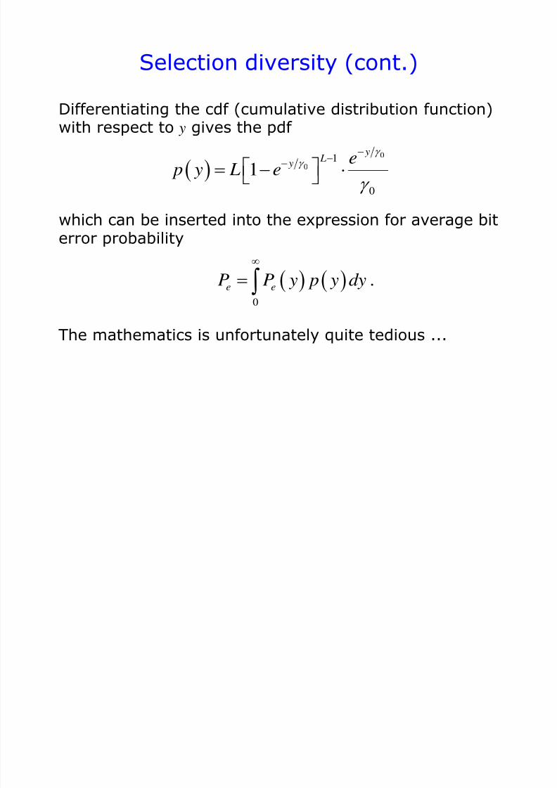
Selection diversity (cont.)
Differentiating the cdf (cumulative distribution function)with respect to y gives the pdf
0
01
0
1
y L
y e p y L e
which can be inserted into the expression for average biterror probability
0
.e eP P y p y dy
The mathematics is unfortunately quite tedious ...
7/31/2019 3320 Digital Transm Over Fad Ch
http://slidepdf.com/reader/full/3320-digital-transm-over-fad-ch 45/51
Selection diversity (cont.)
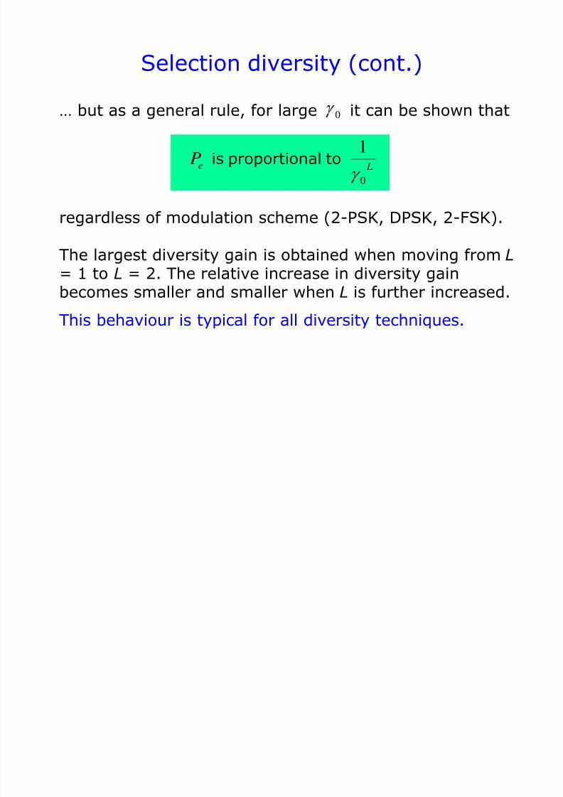
… but as a general rule, for large it can be shown that
0
1e L
P
is proportional to
regardless of modulation scheme (2-PSK, DPSK, 2-FSK).
0
The largest diversity gain is obtained when moving from L= 1 to L = 2. The relative increase in diversity gain
becomes smaller and smaller when L is further increased.This behaviour is typical for all diversity techniques.
7/31/2019 3320 Digital Transm Over Fad Ch
http://slidepdf.com/reader/full/3320-digital-transm-over-fad-ch 46/51
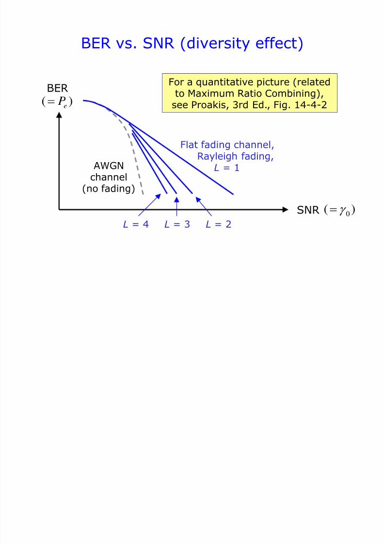
SNR
BER
Flat fading channel,Rayleigh fading,
L = 1AWGNchannel
(no fading)
( )eP
0( )
BER vs. SNR (diversity effect)
L = 2L = 4 L = 3
For a quantitative picture (relatedto Maximum Ratio Combining),see Proakis, 3rd Ed., Fig. 14-4-2

7/31/2019 3320 Digital Transm Over Fad Ch
http://slidepdf.com/reader/full/3320-digital-transm-over-fad-ch 47/51
MRC performance
Rayleigh fading => SNR in i :th diversity branch is
2 2 2
0 0
b b
i i i i
E E a x y
N N
Gaussian distributedquadrature componentsRayleigh distributed magnitude
In case of L uncorrelated branches with same fadingstatistics, the MRC output SNR is
2 2 2 2 2 2 2
1 2 1 1
0 0
b b
L L L
E E a a a x y x y
N N
7/31/2019 3320 Digital Transm Over Fad Ch
http://slidepdf.com/reader/full/3320-digital-transm-over-fad-ch 48/51
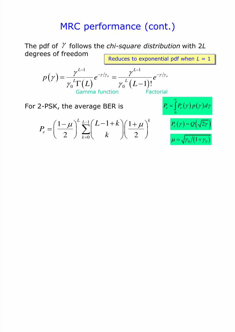
MRC performance (cont.)
The pdf of follows the chi-square distribution with 2L degrees of freedom
1 1
0 0 1 !
o o
L L
L L p e e
L L
Reduces to exponential pdf when L = 1
1
0
11 12 2
L k L
e
k
L k Pk
For 2-PSK, the average BER is 0
e eP P p d
2eP Q
0 01
Gamma function Factorial
7/31/2019 3320 Digital Transm Over Fad Ch
http://slidepdf.com/reader/full/3320-digital-transm-over-fad-ch 49/51
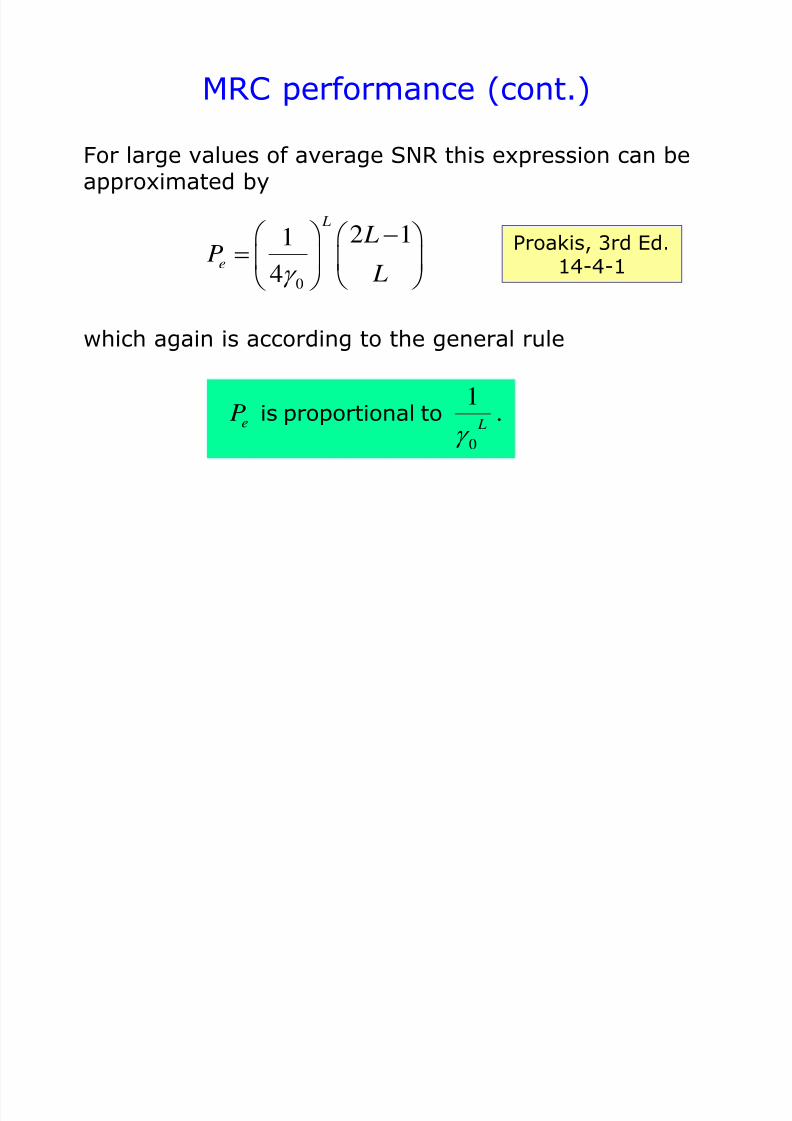
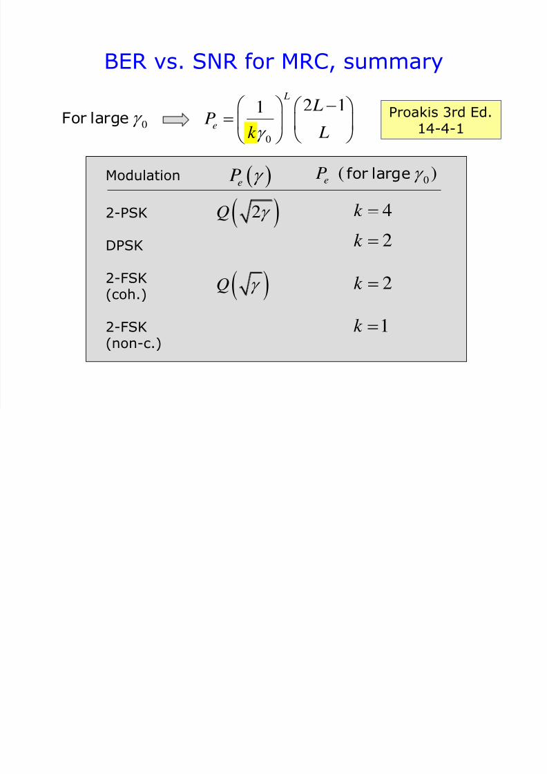
MRC performance (cont.)
For large values of average SNR this expression can beapproximated by
0
2 11
4
L
e
LP
L
which again is according to the general rule
0
1
.e LP is proportional to
Proakis, 3rd Ed.14-4-1
7/31/2019 3320 Digital Transm Over Fad Ch
http://slidepdf.com/reader/full/3320-digital-transm-over-fad-ch 50/51
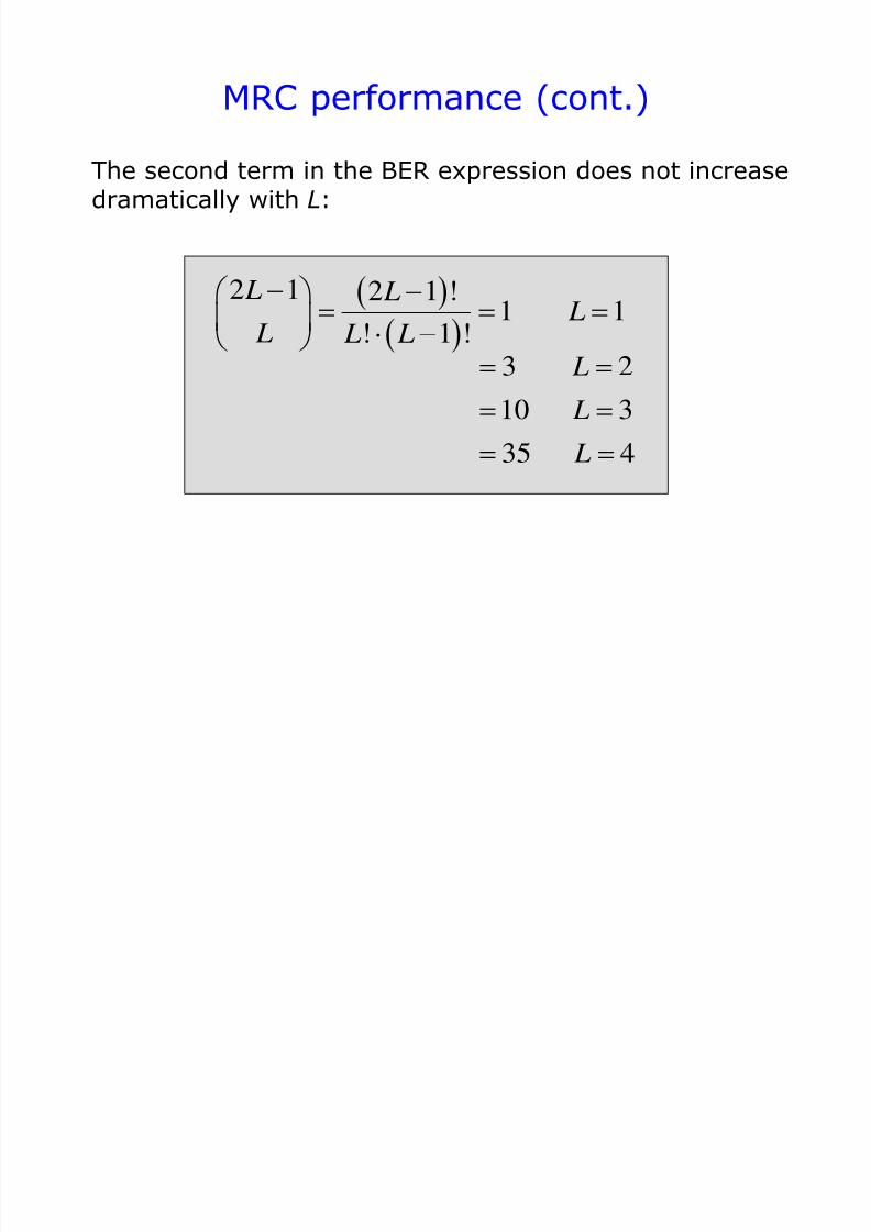
MRC performance (cont.)
The second term in the BER expression does not increasedramatically with L:
2 1 2 1 !
1 1! 1 !
L L L L L L
3 2
10 3
35 4
L
L
L
7/31/2019 3320 Digital Transm Over Fad Ch
http://slidepdf.com/reader/full/3320-digital-transm-over-fad-ch 51/51
BER vs. SNR for MRC, summary
Modulation
2-PSK
DPSK
2-FSK
(coh.)
2-FSK(non-c.)
eP 0( )
eP for large
2Q
Q
0
2 11 L
e
LP
Lk
0 For large
4k
2k
2k
1k
Proakis 3rd Ed.14-4-1