Embed Size (px)
Citation preview
SOLAR INVERTER
Ver.1.3www.gesolarinverter.com
99 Walker Street North Sydney NSW 2060T: +61 [email protected] [email protected]
Global Sales & Service Network
GEP3-5KW SINGLE PHASEUSER MANUAL
* GE is a registered trademark of General Electric Company and is used under license by Jiangsu GoodWe Power Supply Technology Co., Ltd.
© 2020 All Rights Reserved
340-
0043
8-03
1 Symbols ........................................................................................................................... 01
2 Safety Measures & Warning ................................................................ 02
3 Product Introduction ........................................................................................ 04
3.1 Inverter Overview .................................................................................................................. 04
3.2 Package .................................................................................................................................... 05
4 Installation .................................................................................................................... 06
4.1 Mounting Instructions .......................................................................................................... 06
4.2 Equipment Installation ........................................................................................................ 06
4.3 Electrical Connection .......................................................................................................... 08
4.4 Communication Connection ............................................................................................. 12
5 System Operation .............................................................................................. 16
5.1 LCD Panel ............................................................................................................................... 16
5.2 User Interface And System Configuration .................................................................... 17
5.3 Wi-Fi/LAN Reset And Reload............................................................................................ 24
5.4 Precaution For Initial Startup ............................................................................................ 26
5.5 Special Adjustable Setpoints ............................................................................................ 26
6 Troubleshooting .................................................................................................... 29
7 Caution............................................................................................................................ 31
7.1 Checking The DC Switch.............................................................................. 31
7.2 Checking The Electrical Connection............................................................. 31
8 Technical Parameters .................................................................................. 32TAB
LE O
F C
ON
TEN
TS
2 Safety Measures & Warning • The GEP inverter strictly conforms and has been tested according to international safety
regulations.
• The manufacturer strongly advises installers to follow local safety regulations during
commissioning, operation and maintenance of the GEP inverter. Improper operation may result
in electric shocks or damage to equipment and property.
• The installation, maintenance and connection of the inverters must be performed by qualified
personnel, in compliance with local electrical standards, regulations and following the regulations
of the local power suppliers, companies and related authorities.
• If the GEP inverter is unpacked but not put into use immediately, please put it back to the
original package with the desiccant bag and seal it with tape.
• To avoid electric shocks, the DC input and AC output port of the inverters must be disconnected
for at least 5 minutes before performing any installation or maintenance.
• The temperature of some components of the inverters may exceed 60℃ during operation. To
avoid burns, do not touch the inverter during operation. Let the inverter cool before operating.
• Keep children away from the inverter.
• Touching or changing inverter components without following manual instructions may cause
personal injury, damage the inverters and could ultimately invalidate the warranty.
• The electronic components of the inverter could be damaged by static electricity. Appropriate
methods must be adopted to prevent such damage, otherwise the warranty may be null and
void.
• Ensure the output voltage of the proposed PV array is lower than the maximum rated input
voltage of the inverter, otherwise the inverter may be damaged and the warranty may be null
and void.
• When exposed to sunlight, the PV array generates dangerously high DC voltage. We strongly
advise operators strictly follow instructions and avoid actions that put lives at risk.
• The PV modules should have as a minimum an IEC61730 class A rating protection.
• If the equipment is used in a way not authorized by the manufacturer, the equipment built-in
protections may be damaged.
• In order to achieve complete equipment isolation: turn off the AC switch first, then turn off the DC
switch.
• Do not insert or pull the AC or DC terminals when the inverter is in operation.
• An Arc Fault Detector is recommended to be installed on the DC side of an earthing photovltaic
system.
• The inverter can exclude the possibility of DC residual currents to 6mA in the system, Where an
external RCD is required in addition to the built-in RCMU, type A RCD must be used to avoid
tripping.
• The PV is not grounded as default configuration.
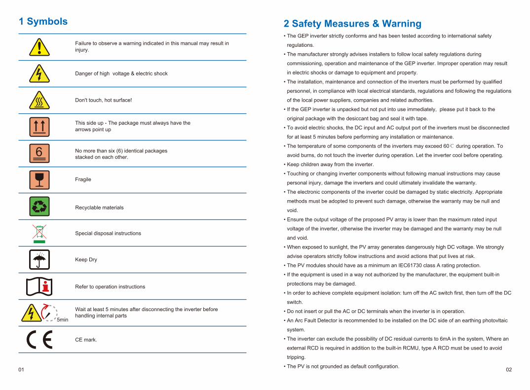
Failure to observe a warning indicated in this manual may result in injury.
Danger of high voltage & electric shock
This side up - The package must always have the arrows point up
Special disposal instructions
Refer to operation instructions
CE mark.
1 Symbols
Don't touch, hot surface!
No more than six (6) identical packagesstacked on each other.
Fragile
Wait at least 5 minutes after disconnecting the inverter before handling internal parts
Keep Dry
Recyclable materials
6
5min
01 02
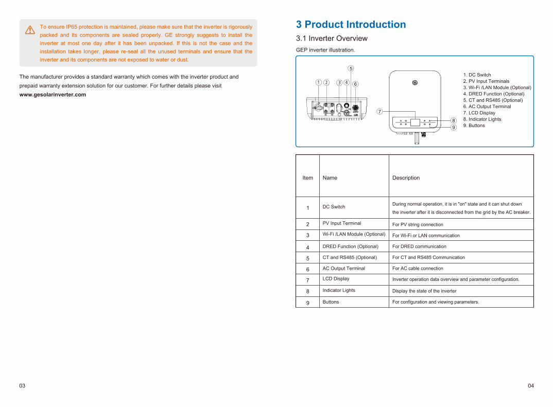
3 Product Introduction3.1 Inverter OverviewGEP inverter illustration.
To ensure IP65 protection is maintained, please make sure that the inverter is rigorously packed and its components are sealed properly. GE strongly suggests to install the inverter at most one day after it has been unpacked. If this is not the case and the installation takes longer, please re-seal all the unused terminals and ensure that the inverter and its components are not exposed to water or dust.
The manufacturer provides a standard warranty which comes with the inverter product and prepaid warranty extension solution for our customer. For further details please visit www.gesolarinverter.com
Item
1
2
3
4
5
6
7
8
9
Name
DC Switch
PV Input Terminal
Wi-Fi /LAN Module (Optional)
DRED Function (Optional)
CT and RS485 (Optional)
AC Output Terminal
LCD Display
Indicator Lights
Buttons
Description
During normal operation, it is in "on" state and it can shut down
the inverter after it is disconnected from the grid by the AC breaker.
For PV string connection
For Wi-Fi or LAN communication
For DRED communication
For CT and RS485 Communication
For AC cable connection
Inverter operation data overview and parameter configuration.
Display the state of the inverter
For configuration and viewing parameters.
1. DC Switch 2. PV Input Terminals3. Wi-Fi /LAN Module (Optional)4. DRED Function (Optional)5. CT and RS485 (Optional) 6. AC Output Terminal7. LCD Display8. Indicator Lights9. Buttons
5
6
7
89
03 04
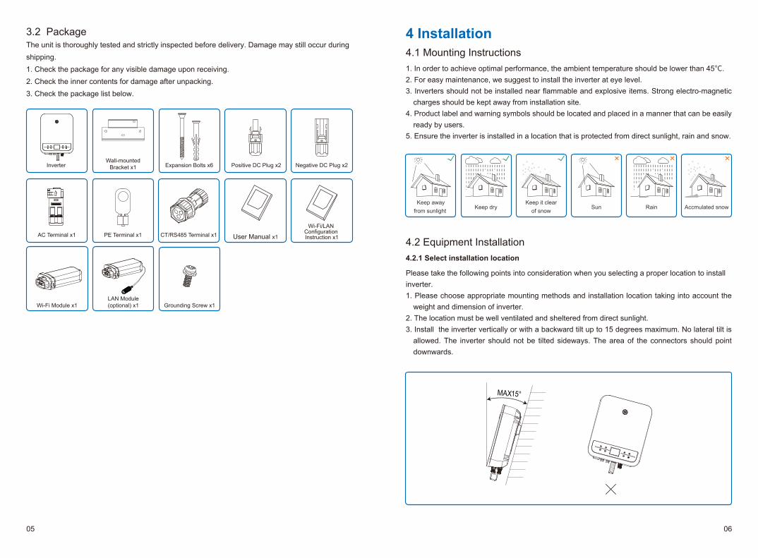
4.2 Equipment Installation4.2.1 Select installation location
Please take the following points into consideration when you selecting a proper location to install inverter. 1. Please choose appropriate mounting methods and installation location taking into account the
weight and dimension of inverter.2. The location must be well ventilated and sheltered from direct sunlight.3. Install the inverter vertically or with a backward tilt up to 15 degrees maximum. No lateral tilt is
allowed. The inverter should not be tilted sideways. The area of the connectors should point downwards.
4 Installation4.1 Mounting Instructions 1. In order to achieve optimal performance, the ambient temperature should be lower than 45℃.2. For easy maintenance, we suggest to install the inverter at eye level.3. Inverters should not be installed near flammable and explosive items. Strong electro-magnetic
charges should be kept away from installation site.4. Product label and warning symbols should be located and placed in a manner that can be easily
ready by users.5. Ensure the inverter is installed in a location that is protected from direct sunlight, rain and snow.
Accmulated snowKeep away
from sunlight Keep dry
Keep it clearof snow
Sun Rain
3.2 PackageThe unit is thoroughly tested and strictly inspected before delivery. Damage may still occur during shipping.1. Check the package for any visible damage upon receiving.2. Check the inner contents for damage after unpacking.3. Check the package list below.
Positive DC Plug x2 Negative DC Plug x2Inverter
AC Terminal x1
Grounding Screw x1
User Manual x1
Wi-Fi/LAN Configuration Instruction x1
Wi-Fi Module x1
PE Terminal x1
Expansion Bolts x6Wall-mounted
Bracket x1
MAX15°
LAN Module(optional) x1
CT/RS485 Terminal x1
05 06
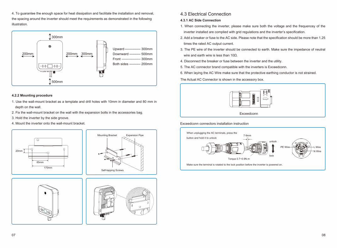
4. To guarantee the enough space for heat dissipation and facilitate the installation and removal, the spacing around the inverter should meet the requirements as demonstrated in the following illustration.
4.2.2 Mounting procedure
1. Use the wall-mount bracket as a template and drill holes with 10mm in diameter and 80 mm in depth on the wall.
2. Fix the wall-mount bracket on the wall with the expansion bolts in the accessories bag.3. Hold the inverter by the side groove.4. Mount the inverter onto the wall-mount bracket.
170mm
85mm
20mm
UpwardDownwardFrontBoth sides
-------------- 300mm---------- 500mm
----------------- 300mm---------- 200mm
200mm 300mm200mm
300mm
500mm
Mounting Bracket Expansion Pipe
Self-tapping Screws
4.3 Electrical Connection4.3.1 AC Side Connection
1. When connecting the inverter, please make sure both the voltage and the frequencey of the
inverter installed are complied with grid regulations and the inverter’s specification.
2. Add a breaker or fuse to the AC side. Please note that the specification should be more than 1.25
times the rated AC output current.
3. The PE wire of the inverter should be connected to earth. Make sure the impedance of neutral
wire and earth wire is less than 10Ω.
4. Disconnect the breaker or fuse between the inverter and the utility.
5. The AC connector brand compatible with the inverters is Exceedconn.
6. When laying the AC Wire make sure that the protective earthing conductor is not strained.
Exceedconn
Exceedconn connectors installation instruction
7-9mm
Torque 0.7~0.9N.m
unlock
lock
When unplugging the AC terminals, press the
button and hold it to unlock
Make sure the terminal is rotated to the lock position before the inverter is powered on.
N Wire
PE Wire L Wire
The Actual AC Connector is shown in the accessory box.
07 08
* Neutral wire is blue, live wire is brown (preferred) or black and protective earth wire is yellow-green.
* Rotate (tightening torque: 0.6N.m) the connector of AC cable into the corresponding terminal.
4.3.2 AC circuit breaker and leakage current protection device
Please install an independent two pole circuit breaker to protect the inverter and make sure it is safe to disconnect it from the grid.
In addition to the built-in RCMU, an external RCD is required to ensure that the inverter system does not carry DC residual currents. To avoid tripping, the types A can be used.
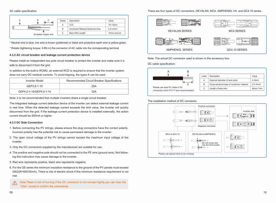
Annealed copper wire
Grade
A
B
C
Description
O.D.
Conductor Material Sectional Area
Bare Wire Length
Value
10~12mm
2.5~4mm2
10mm around
A B C
AC cable specification
Note: it is not recommended that multiple inverters share a single circuit breaker.
The integrated leakage current detection device of the inverter can detect external leakage current in real time. When the detected leakage current exceeds the limit value, the inverter will quickly disconnect from the grid. If the leakage current protection device is installed externally, the action current should be 300mA or higher.
4.3.3 DC Side Connection
1. Before connecting the PV strings, please ensure the plug connectors have the correct polarity. Incorrect polarity has the potential risk to cause permanent damage to the inverter.
2. The open circuit voltage of the PV strings cannot exceed the maximum input voltage of the inverter.
3. Only the DC connectors supplied by the manufacturer are suitable for use.
4. The positive and negative pole should not be connected to the PE wire (ground wire). Not follow-ing this instruction may cause damage to the inverter.
5. Red wire represents positive, black wire represents negative.
6. For the GE series the minimum insulation resistance to the ground of the PV panels must exceed 20kΩ(R=600/30mA). There is risk of electric shock if this minimum resistance requirement is not met.
Inverter Model
GEP3.6-1-10
GEP4.2-1-10/GEP5.0-1-10
Recommended Circuit Breaker Specifications
25A
32A
Please use solar PV cable in DC connection.(4mm PV1-F wire recommended)
There are four types of DC connectors, DEVALAN, MC4, AMPHENDL H4 and QC4.10 series.
DEVALAN SERIES MC4 SERIES
AMPHENOL SERIES QC4.10 SERIES
Note: The actual DC connector used is shown in the accessory box.
DC cable specification:
Value
4~5mm
2.5~4mm2
About 7mm
Label
A
B
C
Description
External diameter of wire stock
Cross-sectional area of conductor material
Length of bare wire
A B
C
Please use special tools to do crimping
MC4 & QC4.10 DEVALAN & AMPHENOL
Do not crimp wire into the limit buckle.
Negative connector
Positive connector
Inverter side
The installation method of DC connector.
Note:There is risk of burning if the DC connector is not connect tightly,you can hear the “Click” sound to confirm the connectivity.
09 10
4.4 Communication ConnectionAfter the replacement of the Wi-Fi/LAN, the new module can work only after restarting PV array connected to the inverter.
4.4.1 Wi-Fi CommunicationWi-Fi communication option is only applicable to Wi-Fi version inverter and Wi-Fi communication module is required. Please refer to "Wi-Fi Configuration Instruction" in the accessory box for detailed instruction. The Wi-Fi module installation of the GEP inverter is shown as below:
4.4.2 LAN Communication (optional)
LAN Communication is only application to LAN version inverter and LAN Communication module is required.
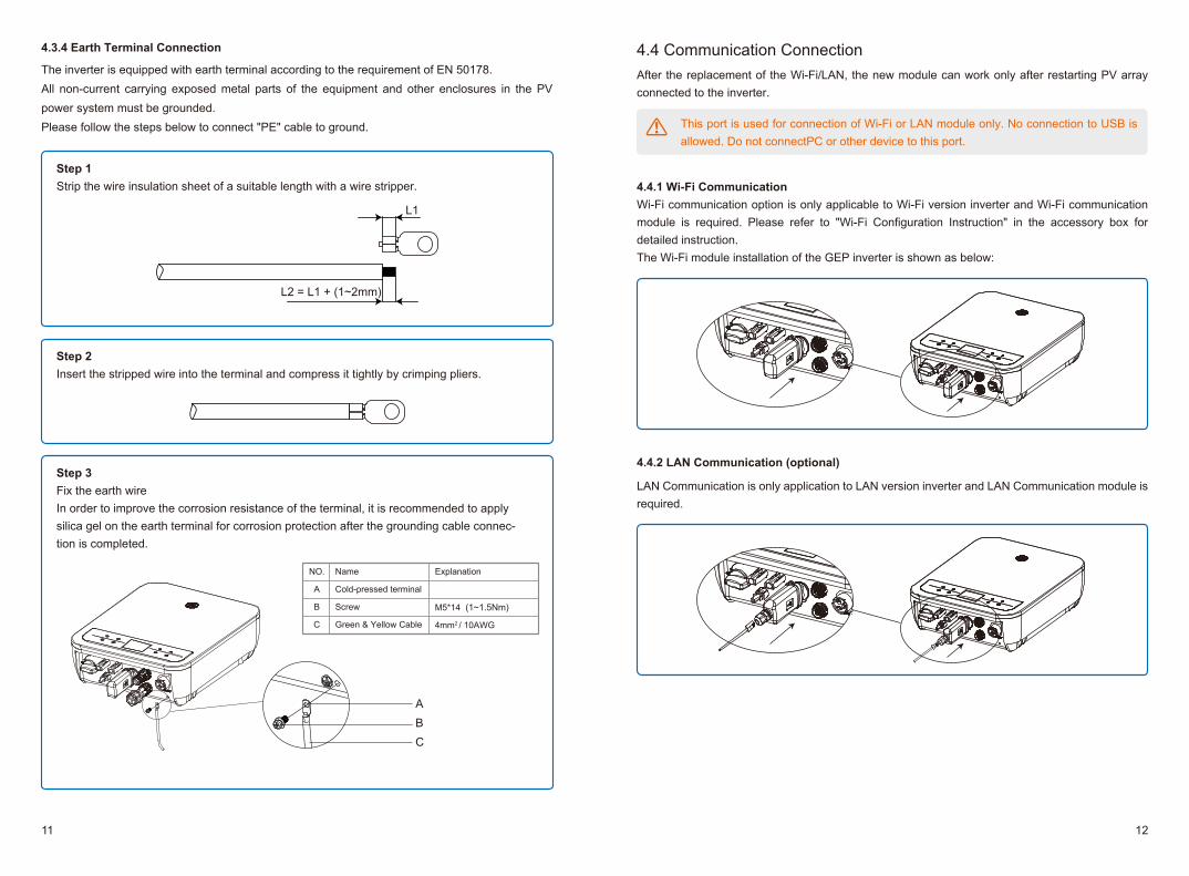
4.3.4 Earth Terminal Connection
The inverter is equipped with earth terminal according to the requirement of EN 50178.All non-current carrying exposed metal parts of the equipment and other enclosures in the PV power system must be grounded.Please follow the steps below to connect "PE" cable to ground.
ABC
NO.
A
B
C
Name
Cold-pressed terminal
Screw
Green & Yellow Cable
Explanation
M5*14 (1~1.5Nm)
4mm2 / 10AWG
L1
L2 = L1 + (1~2mm)
Step 1Strip the wire insulation sheet of a suitable length with a wire stripper.
Step 2Insert the stripped wire into the terminal and compress it tightly by crimping pliers.
Step 3 Fix the earth wire In order to improve the corrosion resistance of the terminal, it is recommended to apply silica gel on the earth terminal for corrosion protection after the grounding cable connec-tion is completed.
This port is used for connection of Wi-Fi or LAN module only. No connection to USB is allowed. Do not connectPC or other device to this port.
11 12
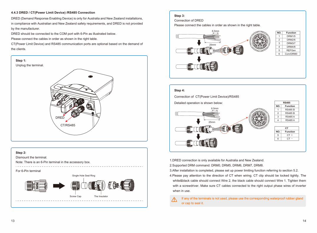
1.DRED connection is only available for Australia and New Zealand.2.Supported DRM command: DRM0, DRM5, DRM6, DRM7, DRM8.3.After installation is completed, please set up power limiting function referring to section 5.2.4.Please pay attention to the direction of CT when wiring. CT clip should be locked tightly. The
white&black cable should connect Wire 2, the black cable should connect Wire 1. Tighten them with a screwdriver. Make sure CT cables connected to the right output phase wires of inverter when in use.
6.5mm
25mm
FunctionDRM1/5DRM2/6DRM3/7DRM4/8REFGen
Com/DRM0
NO.123456
6.5mm
25mm
4.4.3 DRED / CT(Power Limit Device) /RS485 Connection
DRED (Demand Response Enabling Device) is only for Australia and New Zealand installations, in compliance with Australian and New Zealand safety requirements, and DRED is not provided by the manufacturer.DRED should be connected to the COM port with 6-Pin as illustrated below. Please connect the cables in order as shown in the right table.CT(Power Limit Device) and RS485 communication ports are optional based on the demand of the clients.
FunctionCT +CT -
NO.56
CT
FunctionRS485 BRS485 BRS485 ARS485 A
NO.1234
RS485
Step 4:
Connection of CT(Power Limit Device)/RS485
Detailed operation is shown below:
Step 1:Unplug the terminal.
For 6-Pin terminalSingle Hole Seal Ring
Step 2:Dismount the terminal.Note: There is an 6-Pin terminal in the accessory box.
Step 3:Connection of DREDPlease connect the cables in order as shown in the right table.
Screw Cap The Insulator
DRED
CT/RS485
If any of the terminals is not used, please use the corresponding waterproof rubber gland or cap to seal it.
13 14
4.4.5 Earth Fault Alarm(Only for Australia and New Zealand)
In compliance with the section 13.9 of IEC62109-2, the GEP inverter is equipped with an earth fault alarm. When earth fault occurs, the fault indicator at the front LED screen will light up. On inverters with Wi-Fi communication, the system sends an email with the fault notification to the customer. For inverters without Wi-Fi, the buzzer of the inverter will keep ringing for one minute and ring again at 30-minute intervals until the fault is resolved. (This function is only available in Austra-lia and New Zealand).
4.4.6 Monitoring Portal
Portal is an on-wire monitoring system. After completing the installation of commu-nication connection, you can access portal.gesolarinverter.com or download the ‘Power Sight’ App by scanning the QR code to monitor your PV plant and device.Please contact after-sales for further details.
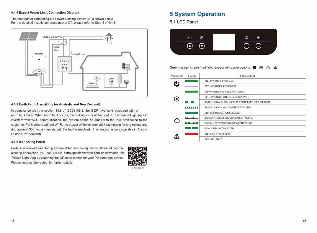
4.4.4 Export Power Limit Connection Diagram
The methods of connecting the Power Limiting device CT is shown below.For the detailed installation procedure of CT, please refer to Step 4 of 4.4.3.
white & Black Wire
Inverter Switch BoardL N
Router
BlackWire
CT
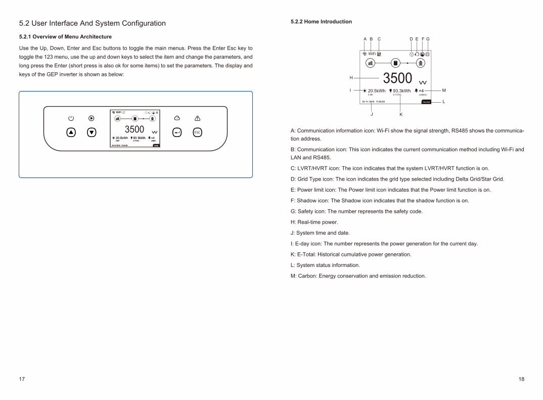
5 System Operation5.1 LCD Panel
Green / green /green / red light respectively correspond to:
EXPLANATION
ON = INVERTER POWER-ON
OFF = INVERTER POWER-OFF
ON = INVERTER IS FEEDING POWER
OFF = INVERTER IS NOT FEEDING POWER
SINGLE SLOW FLASH = SELF CHECK BEFORE GRID CONNECT
SINGLE FLASH = WILL CONNECT WITH GRID
ON = COMMUNICATION SUCCESS
BLINK 2 = ROUTER COMMUNICATION FAILURE
BLINK 4 = SERVER COMMUNICATION FAILURE
BLINK = RS485 CONNECTED
ON = FAULT OCCURRED
OFF = NO FAULT
INDICATOR STATUS
Power Sight
15 1615 16
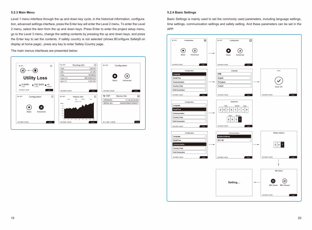
5.2.1 Overview of Menu Architecture
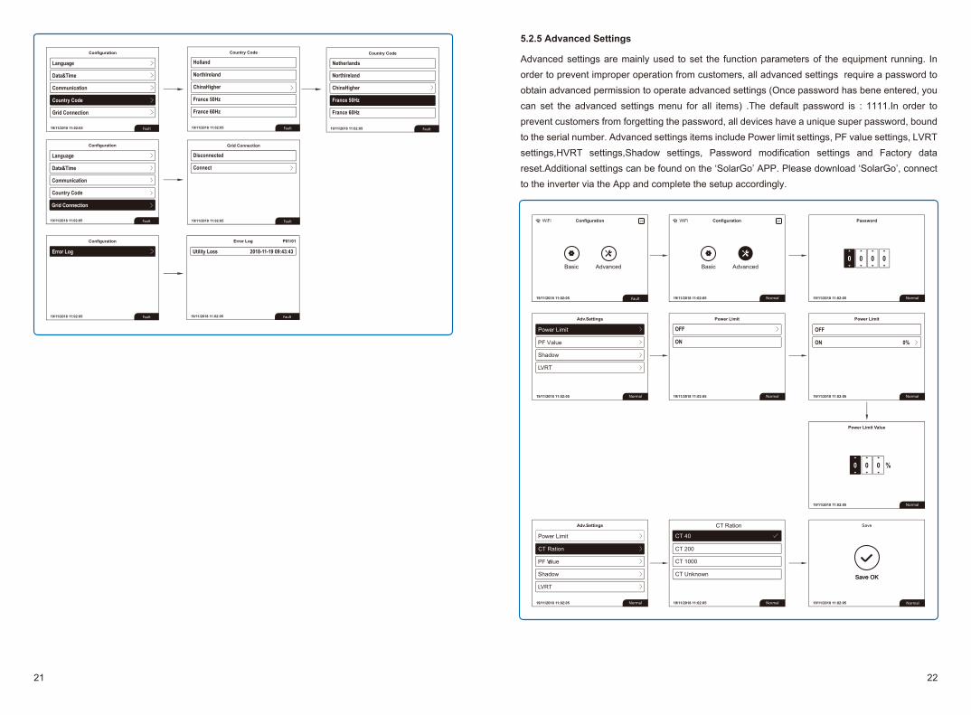
Use the Up, Down, Enter and Esc buttons to toggle the main menus. Press the Enter Esc key to toggle the 123 menu, use the up and down keys to select the item and change the parameters, and long press the Enter (short press is also ok for some items) to set the parameters. The display and keys of the GEP inverter is shown as below:
E-DAY E-TOTAL CARBON
W
x
350020.5
/ / Normal
5.2 User Interface And System Configuration
A: Communication information icon: Wi-Fi show the signal strength, RS485 shows the communica-tion address.
B: Communication icon: This icon indicates the current communication method including Wi-Fi and LAN and RS485.
C: LVRT/HVRT icon: The icon indicates that the system LVRT/HVRT function is on.
D: Grid Type icon: The icon indicates the grid type selected including Delta Grid/Star Grid.
E: Power limit icon: The Power limit icon indicates that the Power limit function is on.
F: Shadow icon: The Shadow icon indicates that the shadow function is on.
G: Safety icon: The number represents the safety code.
H: Real-time power.
J: System time and date.
I: E-day icon: The number represents the power generation for the current day.
K: E-Total: Historical cumulative power generation.
L: System status information.
M: Carbon: Energy conservation and emission reduction.
5.2.2 Home Introduction
E-DAY E-TOTAL CARBON
Normal
W
x
350020.5
/ /
A B DC E F G
H
I
J K
L
M
17 18
5.2.3 Main Menu
Level 1 menu interface through the up and down key cycle, in the historical information, configura-tion, advanced settings interface, press the Enter key will enter the Level 2 menu. To enter the Level 2 menu, select the item from the up and down keys. Press Enter to enter the project setup menu, go to the Level 3 menu, change the setting contents by pressing the up and down keys, and press the Enter key to set the contents. If safety country is not selected (shows �Configure Safety� on display at home page) , press any key to enter Safety Country page.
The main menus interfaces are presented below:
Configuration
Normal/ /
VERSION : V1.02.02.00.06
SERIA NO.: 95000PSB207W8007
Device Info
Vac 230.0V
Iac 21.3A
Fac 50.00Hz
Vpv1/ 2
Ipv1/ 2
300.0/300.0V
5.0/5.0A
Running Info
Configuration History InfoYearMonthDayHour
5.2.4 Basic Settings
Basic Settings is mainly used to set the commonly used parameters, including language settings, time settings, communication settings and safety setting. And these parameters can be set in the APP.
/
/ /
19 20
5.2.5 Advanced Settings
Advanced settings are mainly used to set the function parameters of the equipment running. In order to prevent improper operation from customers, all advanced settings require a password to obtain advanced permission to operate advanced settings (Once password has bene entered, you can set the advanced settings menu for all items) .The default password is : 1111.In order to prevent customers from forgetting the password, all devices have a unique super password, bound to the serial number. Advanced settings items include Power limit settings, PF value settings, LVRT settings,HVRT settings,Shadow settings, Password modification settings and Factory data reset.Additional settings can be found on the ‘SolarGo’ APP. Please download ‘SolarGo’, connect to the inverter via the App and complete the setup accordingly.
CT Ration
CT 200
CT 1000
CT Unknown
CT 40
Power Limit
PF Value
Shadow
LVRT
Power Limit
PF Value
Shadow
LVRT
CT Ration
Netherlands
21 22
HVRT
Password
Grid Type
Factory Data Reset
HVRT
Password
Grid Type
Factory Data Reset
HVRT
Password
Grid Type
Factory Data Reset
0 0 0 0
0 0 00
Old
New
Power Limit
Shadow
LVRT
CT Ration
PF Value
Power Limit
LVRT
CT Ration
PF Value
Shadow
Power Limit
CT Ration
PF Value
Shadow
LVRT
√
5.2.6 History Information
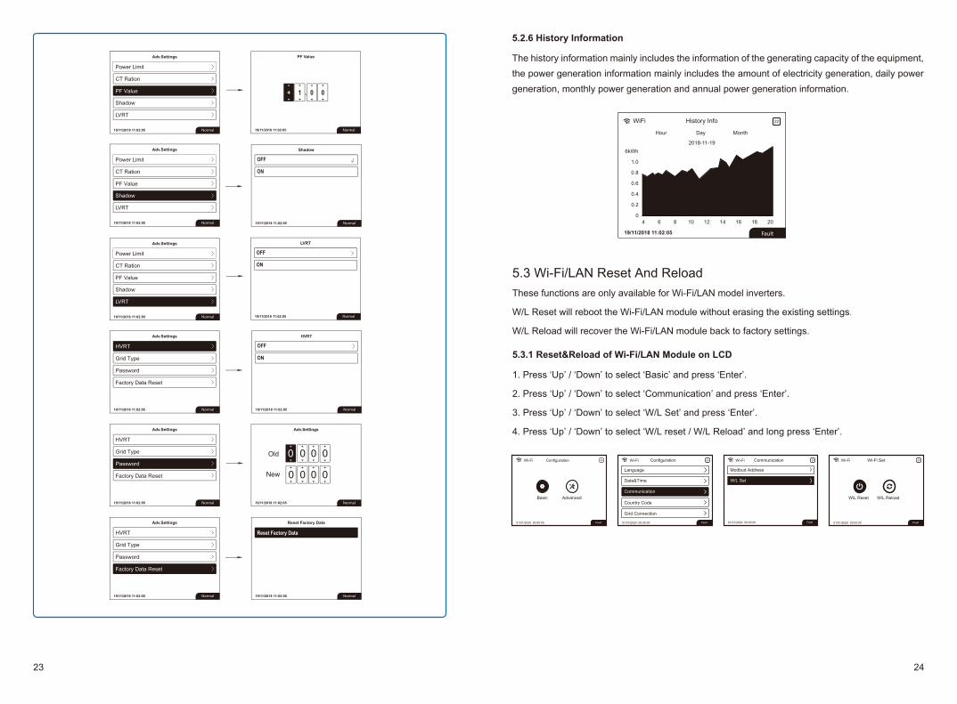
The history information mainly includes the information of the generating capacity of the equipment, the power generation information mainly includes the amount of electricity generation, daily power generation, monthly power generation and annual power generation information.
5.3 Wi-Fi/LAN Reset And ReloadThese functions are only available for Wi-Fi/LAN model inverters.
W/L Reset will reboot the Wi-Fi/LAN module without erasing the existing settings.
W/L Reload will recover the Wi-Fi/LAN module back to factory settings.
5.3.1 Reset&Reload of Wi-Fi/LAN Module on LCD
1. Press ‘Up’ / ‘Down’ to select ‘Basic’ and press ‘Enter’.
2. Press ‘Up’ / ‘Down’ to select ‘Communication’ and press ‘Enter’.
3. Press ‘Up’ / ‘Down’ to select ‘W/L Set’ and press ‘Enter’.
4. Press ‘Up’ / ‘Down’ to select ‘W/L reset / W/L Reload’ and long press ‘Enter’.
Basic Advanced
01/01/2020 00:00:00 Fault
Wi-Fi Configuration 22 Wi-Fi 22
01/01/2020 00:00:00 Fault
Configuration
Language
Data&Time
Communication
Country Code
Grid Connection
W/L ReloadW/L Reset
01/01/2020 00:00:00 Fault
Wi-Fi Wi-Fi Set 22Wi-Fi 22
01/01/2020 00:00:00 Fault
Communication
Modbud Address
W/L Set
23 24
5.4 Precaution For Initial Startup1. Make sure the AC circuit is connected and AC the breaker is turned off.2. Make sure the DC cable between inverter and PV string is connected, and the PV voltage is
normal.3. Turn on the DC switch, and set safety country according to the local regulation.4. Turn on the AC breaker. Check the inverter work is working normally.
5.5 Special Adjustable Setpoints(Only for Australia and New Zealand)The inverter has a field in which the user can set functions, such as trip points, trip times, reconnect times, active and inactive QU curves and PU curves. It is adjustable through special software. If needed, please contact after-sales. To obtain software manuals, you can download them from the official website or contact after-sales.
5.5.1 PF Power Curve Mode
PF power curve mode can be modified by Modbus communication method, specifically accordingto the inverter Modbus address and Modbus register value, according to the set range in the set thecorresponding value.
A
B
C
Power, (%P/P rated)1.0
0.95
0.95
0% 25%
50%
75%
100%
cosФ
LEGEND:
cosФ
LEA
DIN
GLA
GG
ING
5.3.2 Reload of Wi-Fi/LAN Module using Button
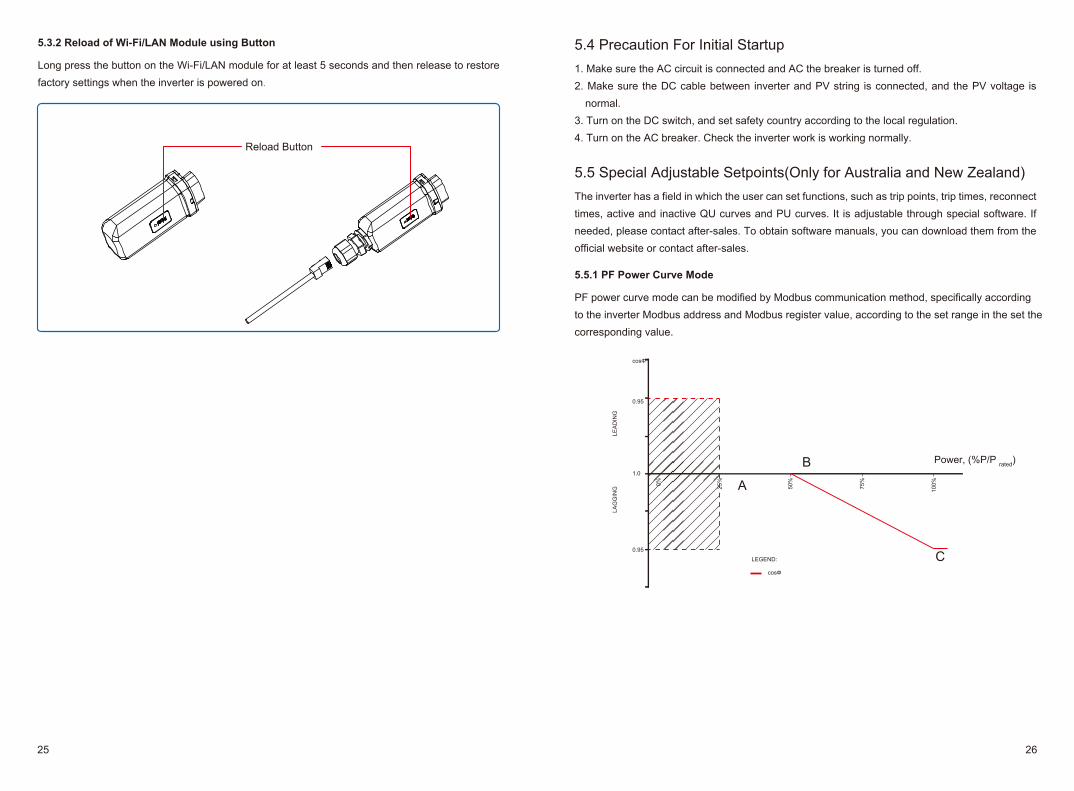
Long press the button on the Wi-Fi/LAN module for at least 5 seconds and then release to restore factory settings when the inverter is powered on.
Reload Button
25 26
5.5.3 QU Curve Mode
QU curve mode can be modified by Modbus communication, specifically according to theinverter Modbus address and Modbus register value, according to the set range to set thecorresponding value.
5.5.4 Power Recovery Rate
The power recovery rate can be modified by Modbus communication, specifically according tothe inverter Modbus address and Modbus register value, according to the set range to set thecorresponding value.
FunctionPower recovery rate Settings
The default value (Australia & New Zealand)
16(16%Pn/min)
Register40536
Setting range5~100
If you need to change the above Settings, please contact our after-sales service.
40%V1 V2 V3 V4
LEA
DIN
GLE
AD
ING
VA
R/R
ATE
D, V
A (%
)
INVERTER VOLTAGE, V
var characteristic curveLEGEND:
30%
20%
10%
0%
10%
200
210
230
240
260
270
20%
30%
40%
220
250
40%V1 V2 V3 V4
LEA
DIN
GLE
AD
ING
VA
R/R
ATE
D, V
A (%
)
INVERTER VOLTAGE, V
var characteristic curveLEGEND:
30%
20%
10%
0%
10%
200
210
230
240
260
270
20%
30%
40%
220
250
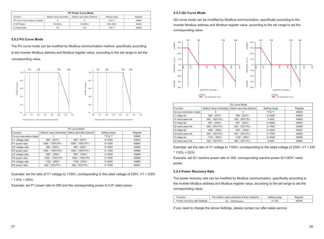
QU curve ModeFunctionQU curve mode enable or disableV1 voltage ratioQ1 reactive power ratioV2 voltage ratioQ2 reactive power ratioV3 voltage ratioQ3 reactive power ratioV4 voltage ratioQ4 reactive power ratio
Default value (Australia)0
900(207V)300(30%*Pn)
957(220V)300(30%*Pn)1087(250V)
300(30%*Pn)1152(265V)
300(30%*Pn)
Default value (New Zealand)0
900(207V)300(30%*Pn)
957(220V)300(30%*Pn)1061(244V)
300(30%*Pn)1109(255V)
300(30%*Pn)
Setting range“0”or“1”0~20000~600
0~20000~15000~20000~15000~20000~600
Register406504065340654406554065640657406584065940660
Example: set the ratio of V1 voltage to 1100V, corresponding to the rated voltage of 230V, V1 = 230
* 110% = 253V.
Example: set Q1 reactive power ratio to 300, corresponding reactive power Q1=30%* rated
power.
5.5.2 PU Curve Mode
The PU curve mode can be modified by Modbus communication method, specifically according
to the inverter Modbus address and Modbus register value, according to the set range to set the
corresponding value.
PF Power Curve ModeFunction
PF curve mode enable or disable
B %P/Prated
C Power factor
Default value (Australia)
0
50 (50%)
0.9
Default value (New Zealand)
0
50 (50%)
0.9
Setting range
“0”or“1”
30%~80%
0.8~1
Register
40600
40603
40606
V1 V2 V3 V4 V1 V2 V3 V4100%
80%
60%
40%
20%
0%200 210 220 230 240 250 260 270
PO
WE
R, P
/Pra
ted%
100%
80%
60%
40%
20%
0%200 210 220 230 240 250 260 270
PO
WE
R, P
/Pra
ted%
Example curve for a volt-watt response mode (Australia) Example curve for a volt-watt response mode (New Zealand)
PU curve ModeFunctionPU curve mode enable or disableV1 voltage ratioP1 power ratioV2 voltage ratioP2 power ratioV3 voltage ratioP3 power ratioV4 voltage ratioP4 power ratio
Default value (Australia)1
900(207V)1000(100%*Pn)
956(220V)1000(100%*Pn)
1087(250V)1000(100%*Pn1152(265V)
200(20%*Pn)
Default value (New Zealand)1
900(207V)1000(100%*Pn)
956(220V)1000(100%*Pn)
1061(244V)1000(100%*Pn1109(255V)
200(20%*Pn)
Setting range““0”or“1”0~20000~15000~20000~15000~20000~15000~20000~1500
Register406804068340684406854068640688406894069040691
Example: set the ratio of V1 voltage to 1100V, corresponding to the rated voltage of 230V, V1 = 230V
* 110% = 253V.
Example: set P1 power ratio to 900 and the corresponding power to 0.9* rated power.
27 28
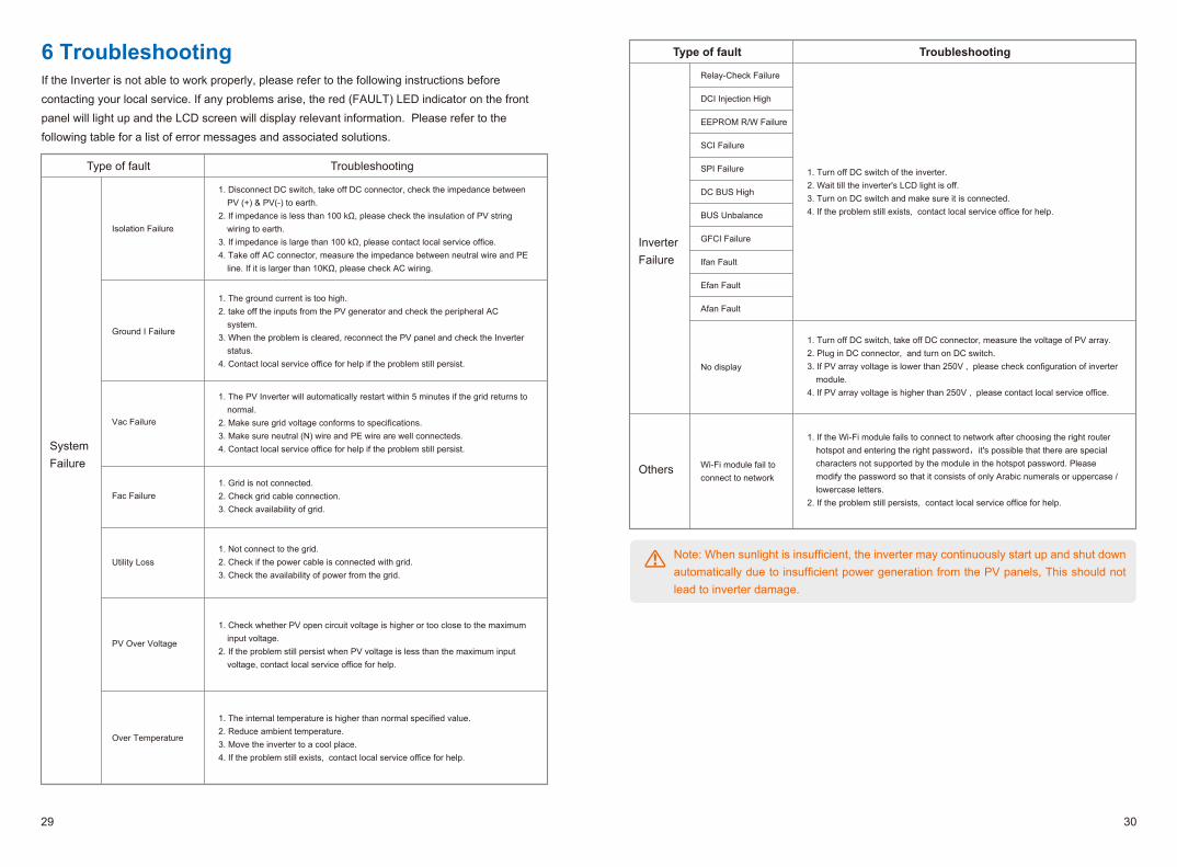
Note: When sunlight is insufficient, the inverter may continuously start up and shut down automatically due to insufficient power generation from the PV panels, This should not lead to inverter damage.
1. Turn off DC switch of the inverter.2. Wait till the inverter's LCD light is off.3. Turn on DC switch and make sure it is connected.4. If the problem still exists, contact local service office for help.
1. Turn off DC switch, take off DC connector, measure the voltage of PV array.2. Plug in DC connector, and turn on DC switch.3. If PV array voltage is lower than 250V , please check configuration of inverter
module.4. If PV array voltage is higher than 250V , please contact local service office.
Type of fault Troubleshooting
Relay-Check Failure
DCI Injection High
EEPROM R/W Failure
SCI Failure
SPI Failure
DC BUS High
BUS Unbalance
GFCI Failure
Ifan Fault
Efan Fault
Afan Fault
No display
Wi-Fi module fail toconnect to network
InverterFailure
Others
1. If the Wi-Fi module fails to connect to network after choosing the right router hotspot and entering the right password,it's possible that there are special characters not supported by the module in the hotspot password. Please modify the password so that it consists of only Arabic numerals or uppercase / lowercase letters.
2. If the problem still persists, contact local service office for help.
6 TroubleshootingIf the Inverter is not able to work properly, please refer to the following instructions before contacting your local service. If any problems arise, the red (FAULT) LED indicator on the front panel will light up and the LCD screen will display relevant information. Please refer to the following table for a list of error messages and associated solutions.
1. Disconnect DC switch, take off DC connector, check the impedance between PV (+) & PV(-) to earth.
2. If impedance is less than 100 kΩ, please check the insulation of PV string wiring to earth.
3. If impedance is large than 100 kΩ, please contact local service office.4. Take off AC connector, measure the impedance between neutral wire and PE
line. If it is larger than 10KΩ, please check AC wiring.
1. Not connect to the grid.2. Check if the power cable is connected with grid.3. Check the availability of power from the grid.
1. Check whether PV open circuit voltage is higher or too close to the maximum input voltage.
2. If the problem still persist when PV voltage is less than the maximum input voltage, contact local service office for help.
1. The internal temperature is higher than normal specified value.2. Reduce ambient temperature.3. Move the inverter to a cool place.4. If the problem still exists, contact local service office for help.
1. The ground current is too high.2. take off the inputs from the PV generator and check the peripheral AC
system. 3. When the problem is cleared, reconnect the PV panel and check the Inverter
status.4. Contact local service office for help if the problem still persist.
1. The PV Inverter will automatically restart within 5 minutes if the grid returns to normal.
2. Make sure grid voltage conforms to specifications.3. Make sure neutral (N) wire and PE wire are well connecteds. 4. Contact local service office for help if the problem still persist.
1. Grid is not connected.2. Check grid cable connection.3. Check availability of grid.
Vac Failure
Fac Failure
Type of fault Troubleshooting
Ground I Failure
Isolation Failure
Over Temperature
PV Over Voltage
Utility Loss
SystemFailure
29 30
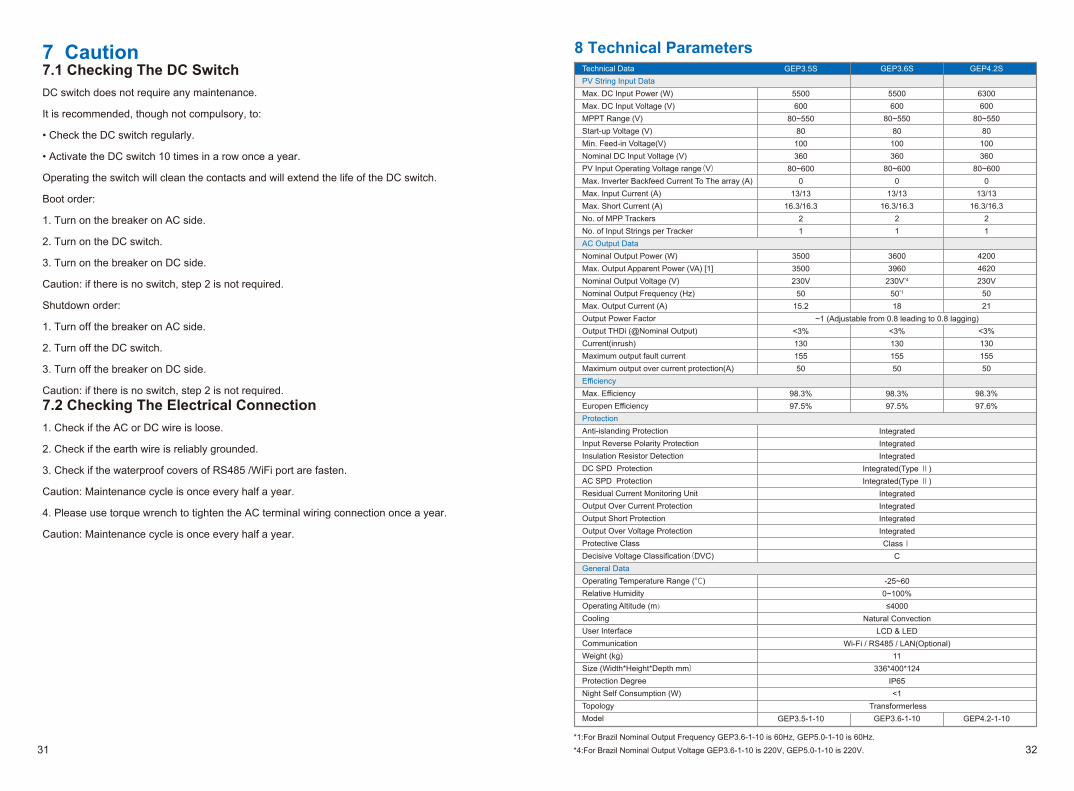
8 Technical ParametersGEP3.5S
5500600
80~55080
100360
80~6000
13/1316.3/16.3
21
35003500230V
5015.2
<3%13015550
98.3%97.5%
GEP3.6S
5500600
80~55080
100360
80~6000
13/1316.3/16.3
21
36003960
230V*4
50*1
18~1 (Adjustable from 0.8 leading to 0.8 lagging)
<3%13015550
98.3%97.5%
IntegratedIntegratedIntegrated
Integrated(Type Ⅱ)Integrated(Type Ⅱ)
IntegratedIntegratedIntegratedIntegratedClassⅠ
C
-25~600~100%≤4000
Natural ConvectionLCD & LED
Wi-Fi / RS485 / LAN(Optional) 11
336*400*124IP65<1
TransformerlessGEP3.6-1-10
GEP4.2S
6300600
80~55080
100360
80~6000
13/1316.3/16.3
21
42004620230V
5021
<3%13015550
98.3%97.6%
Technical DataPV String Input DataMax. DC Input Power (W)Max. DC Input Voltage (V)MPPT Range (V)Start-up Voltage (V)Min. Feed-in Voltage(V)Nominal DC Input Voltage (V)PV Input Operating Voltage range(V)Max. Inverter Backfeed Current To The array (A)Max. Input Current (A)Max. Short Current (A)No. of MPP TrackersNo. of Input Strings per TrackerAC Output DataNominal Output Power (W)Max. Output Apparent Power (VA) [1]Nominal Output Voltage (V)Nominal Output Frequency (Hz)Max. Output Current (A)Output Power FactorOutput THDi (@Nominal Output)Current(inrush)Maximum output fault currentMaximum output over current protection(A)EfficiencyMax. EfficiencyEuropen EfficiencyProtectionAnti-islanding ProtectionInput Reverse Polarity ProtectionInsulation Resistor DetectionDC SPD ProtectionAC SPD ProtectionResidual Current Monitoring UnitOutput Over Current ProtectionOutput Short ProtectionOutput Over Voltage ProtectionProtective ClassDecisive Voltage Classification(DVC)General DataOperating Temperature Range (℃)Relative HumidityOperating Altitude (m)Cooling User InterfaceCommunicationWeight (kg)Size (Width*Height*Depth mm)Protection DegreeNight Self Consumption (W)TopologyModel
*1:For Brazil Nominal Output Frequency GEP3.6-1-10 is 60Hz, GEP5.0-1-10 is 60Hz.
*4:For Brazil Nominal Output Voltage GEP3.6-1-10 is 220V, GEP5.0-1-10 is 220V.
7 Caution7.1 Checking The DC SwitchDC switch does not require any maintenance.
It is recommended, though not compulsory, to:
• Check the DC switch regularly.
• Activate the DC switch 10 times in a row once a year.
Operating the switch will clean the contacts and will extend the life of the DC switch.
Boot order:
1. Turn on the breaker on AC side.
2. Turn on the DC switch.
3. Turn on the breaker on DC side.
Caution: if there is no switch, step 2 is not required.
Shutdown order:
1. Turn off the breaker on AC side.
2. Turn off the DC switch.
3. Turn off the breaker on DC side.
Caution: if there is no switch, step 2 is not required.7.2 Checking The Electrical Connection1. Check if the AC or DC wire is loose.
2. Check if the earth wire is reliably grounded.
3. Check if the waterproof covers of RS485 /WiFi port are fasten.
Caution: Maintenance cycle is once every half a year.
4. Please use torque wrench to tighten the AC terminal wiring connection once a year.
Caution: Maintenance cycle is once every half a year.
GEP3.5-1-10 GEP4.2-1-10
31 32
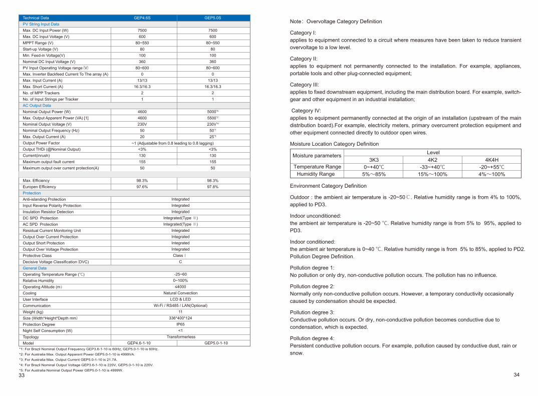
Note:Overvoltage Category Definition
Category I:applies to equipment connected to a circuit where measures have been taken to reduce transient overvoltage to a low level.
Category II:applies to equipment not permanently connected to the installation. For example, appliances, portable tools and other plug-connected equipment;
Category III:applies to fixed downstream equipment, including the main distribution board. For example, switch-gear and other equipment in an industrial installation;
Category IV:applies to equipment permanently connected at the origin of an installation (upstream of the main distribution board).For example, electricity meters, primary overcurrent protection equipment and other equipment connected directly to outdoor open wires.
Moisture Location Category Definition
Environment Category Definition
Outdoor : the ambient air temperature is -20~50℃. Relative humidity range is from 4% to 100%, applied to PD3.
Indoor unconditioned:the ambient air temperature is -20~50 ℃. Relative humidity range is from 5% to 95%, applied to PD3.
Indoor conditioned:the ambient air temperature is 0~40 ℃. Relative humidity range is from 5% to 85%, applied to PD2.Pollution Degree Definition.
Pollution degree 1:No pollution or only dry, non-conductive pollution occurs. The pollution has no influence.
Pollution degree 2:Normally only non-conductive pollution occurs. However, a temporary conductivity occasionally caused by condensation should be expected.
Pollution degree 3:Conductive pollution occurs. Or dry, non-conductive pollution becomes conductive due to condensation, which is expected.
Pollution degree 4:Persistent conductive pollution occurs. For example, pollution caused by conductive dust, rain or snow.
GEP4.6S
7500600
80~55080100360
80~6000
13/1316.3/16.3
21
46004600230V
5020
<3%13015550
98.3%97.6%
IntegratedIntegratedIntegrated
Integrated(Type Ⅱ)Integrated(Type Ⅱ)
IntegratedIntegratedIntegratedIntegratedClassⅠ
C
-25~600~100%≤4000
Natural ConvectionLCD & LED
Wi-Fi / RS485 / LAN(Optional) 11
336*400*124IP65<1
Transformerless
GEP5.0S
7500600
80~55080100360
80~6000
13/1316.3/16.3
21
5000*5
5500*2
230V*4
50*1
25*3
<3%13015550
98.3%97.8%
Technical DataPV String Input DataMax. DC Input Power (W)Max. DC Input Voltage (V)MPPT Range (V)Start-up Voltage (V)Min. Feed-in Voltage(V)Nominal DC Input Voltage (V)PV Input Operating Voltage range(V)Max. Inverter Backfeed Current To The array (A)Max. Input Current (A)Max. Short Current (A)No. of MPP TrackersNo. of Input Strings per TrackerAC Output DataNominal Output Power (W)Max. Output Apparent Power (VA) [1]Nominal Output Voltage (V)Nominal Output Frequency (Hz)Max. Output Current (A)Output Power FactorOutput THDi (@Nominal Output)Current(inrush)Maximum output fault currentMaximum output over current protection(A)EfficiencyMax. EfficiencyEuropen EfficiencyProtectionAnti-islanding ProtectionInput Reverse Polarity ProtectionInsulation Resistor DetectionDC SPD ProtectionAC SPD ProtectionResidual Current Monitoring UnitOutput Over Current ProtectionOutput Short ProtectionOutput Over Voltage ProtectionProtective ClassDecisive Voltage Classification(DVC)General DataOperating Temperature Range (℃)Relative HumidityOperating Altitude (m)Cooling User InterfaceCommunicationWeight (kg)Size (Width*Height*Depth mm)Protection DegreeNight Self Consumption (W)TopologyModel
~1 (Adjustable from 0.8 leading to 0.8 lagging)
*1: For Brazil Nominal Output Frequency GEP3.6-1-10 is 60Hz, GEP5.0-1-10 is 60Hz.*2: For Australia Max. Output Apparent Power GEP5.0-1-10 is 4999VA.*3: For Australia Max. Output Current GEP5.0-1-10 is 21.7A.*4: For Brazil Nominal Output Voltage GEP3.6-1-10 is 220V, GEP5.0-1-10 is 220V.*5: For Australia Nominal Output Power GEP5.0-1-10 is 4999W.
GEP4.6-1-10 GEP5.0-1-10
33 34