Embed Size (px)
Citation preview
Customised MNS EnergyRange
Rear Access11kV/415vPackaged Sub-stations
Introduction 3.5.0
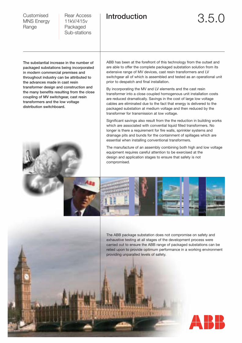
ABB has been at the forefront of this technology from the outset andare able to offer the complete packaged substation solution from itsextensive range of MV devices, cast resin transformers and LVswitchgear all of which is assembled and tested as an operational unitprior to despatch and final installation.
By incorporating the MV and LV elements and the cast resin transformer into a close coupled homogenous unit installation costs are reduced dramatically. Savings in the cost of large low voltagecables are eliminated due to the fact that energy is delivered to thepackaged substation at medium voltage and then reduced by thetransformer for transmission at low voltage.
Significant savings also result from the the reduction in building workswhich are associated with convential liquid filled transformers. Nolonger is there a requirement for fire walls, sprinkler systems anddrainage pits and bunds for the containment of spillages which areessential when installing conventional transformers.
The manufacture of an assembly combining both high and low voltageequipment requires careful attention to be exercised at the design and application stages to ensure that safety is not compromised.
The ABB package substation does not compromise on safety and exhaustive testing at all stages of the development process were carried out to ensure the ABB range of packaged substations can berelied upon to provide optimum performance in a working environmentproviding unparalled levels of safety.
The substantial increase in the number of packaged substations being incorporated in modern commercial premises and throughout industry can be attributed to the advances made in cast resin transformer design and construction and the many benefits resulting from the closecoupling of MV switchgear, cast resin transformers and the low voltage distribution switchboard.
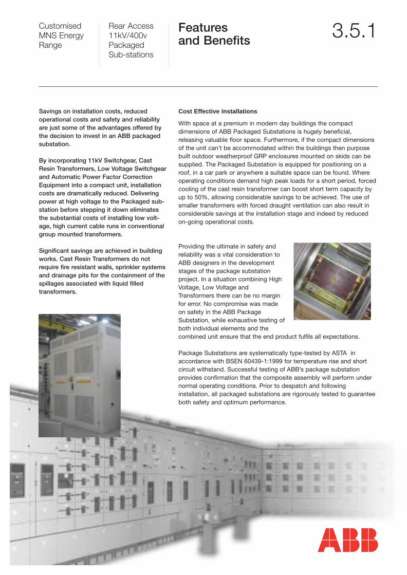
Cost Effective Installations
With space at a premium in modern day buildings the compact dimensions of ABB Packaged Substations is hugely beneficial, releasing valuable floor space. Furthermore, if the compact dimensionsof the unit can’t be accommodated within the buildings then purposebuilt outdoor weatherproof GRP enclosures mounted on skids can besupplied. The Packaged Substation is equipped for positioning on aroof, in a car park or anywhere a suitable space can be found. Whereoperating conditions demand high peak loads for a short period, forcedcooling of the cast resin transformer can boost short term capacity byup to 50%, allowing considerable savings to be achieved. The use ofsmaller transformers with forced draught ventilation can also result inconsiderable savings at the installation stage and indeed by reducedon-going operational costs.
Providing the ultimate in safety andreliability was a vital consideration toABB designers in the developmentstages of the package substation project. In a situation combining HighVoltage, Low Voltage andTransformers there can be no marginfor error. No compromise was madeon safety in the ABB PackageSubstation, while exhaustive testing ofboth individual elements and the combined unit ensure that the end product fulfils all expectations.
Package Substations are systematically type-tested by ASTA in accordance with BSEN 60439-1:1999 for temperature rise and shortcircuit withstand. Successful testing of ABB’s package substation provides confirmation that the composite assembly will perform undernormal operating conditions. Prior to despatch and following installation, all packaged substations are rigorously tested to guaranteeboth safety and optimum performance.
Customised MNS EnergyRange
Rear Access11kV/400vPackaged Sub-stations
Features and Benefits 3.5.1
Savings on installation costs, reduced operational costs and safety and reliabilityare just some of the advantages offered bythe decision to invest in an ABB packaged substation.
By incorporating 11kV Switchgear, CastResin Transformers, Low Voltage Switchgearand Automatic Power Factor CorrectionEquipment into a compact unit, installationcosts are dramatically reduced. Deliveringpower at high voltage to the Packaged sub-station before stepping it down eliminatesthe substantial costs of installing low volt-age, high current cable runs in conventionalgroup mounted transformers.
Significant savings are achieved in buildingworks. Cast Resin Transformers do notrequire fire resistant walls, sprinkler systemsand drainage pits for the containment of thespillages associated with liquid filled transformers.
Customised MNS EnergyRange
Rear Access11kV/400vPackaged Sub-stations
Segregationand Wiring 3.5.7
GENERAL
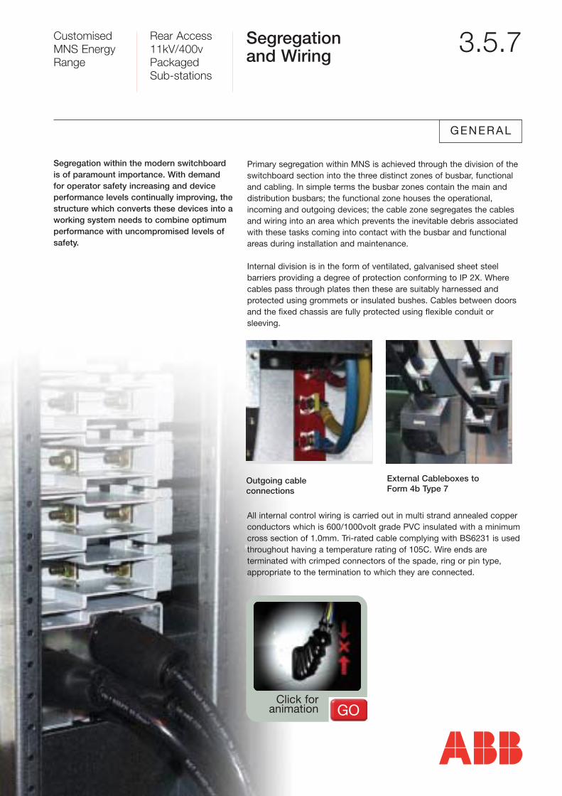
Primary segregation within MNS is achieved through the division of the switchboard section into the three distinct zones of busbar, functionaland cabling. In simple terms the busbar zones contain the main anddistribution busbars; the functional zone houses the operational, incoming and outgoing devices; the cable zone segregates the cablesand wiring into an area which prevents the inevitable debris associatedwith these tasks coming into contact with the busbar and functionalareas during installation and maintenance.
Internal division is in the form of ventilated, galvanised sheet steel barriers providing a degree of protection conforming to IP 2X. Wherecables pass through plates then these are suitably harnessed and protected using grommets or insulated bushes. Cables between doorsand the fixed chassis are fully protected using flexible conduit or sleeving.
All internal control wiring is carried out in multi strand annealed copper conductors which is 600/1000volt grade PVC insulated with a minimumcross section of 1.0mm. Tri-rated cable complying with BS6231 is usedthroughout having a temperature rating of 105C. Wire ends are terminated with crimped connectors of the spade, ring or pin type, appropriate to the termination to which they are connected.
Segregation within the modern switchboardis of paramount importance. With demandfor operator safety increasing and device performance levels continually improving, thestructure which converts these devices into aworking system needs to combine optimumperformance with uncompromised levels ofsafety.
Outgoing cable connections
External Cableboxes to Form 4b Type 7
Click for animation GO
Customised MNS EnergyRange
Rear Access11kV/400vPackaged Sub-stations
Segregation and Wiring -continued
3.5.7a
Internal power wiring is carried out in tri-rated multi strand annealed copper conductors in accordance with BS6231. Insulation colour is blackthroughout with each cable end being clearly identified with phasecoloured tape or strapping. Cables are rated in accordance with the latest edition of the IEE wiring regulations and are provided with crimpedcable plugs of the appropriate size and type.
All cables are clearly identified using indelibly machine printed cable markers located at both ends of the cable.
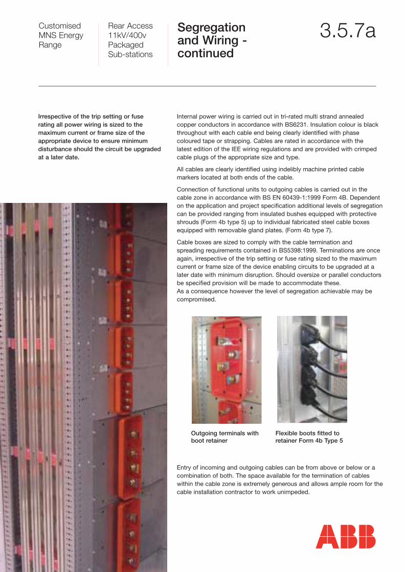
Connection of functional units to outgoing cables is carried out in thecable zone in accordance with BS EN 60439-1:1999 Form 4B. Dependenton the application and project specification additional levels of segregationcan be provided ranging from insulated bushes equipped with protectiveshrouds (Form 4b type 5) up to individual fabricated steel cable boxesequipped with removable gland plates. (Form 4b type 7).
Cable boxes are sized to comply with the cable termination and spreading requirements contained in BS5398:1999. Terminations are onceagain, irrespective of the trip setting or fuse rating sized to the maximumcurrent or frame size of the device enabling circuits to be upgraded at alater date with minimum disruption. Should oversize or parallel conductorsbe specified provision will be made to accommodate these. As a consequence however the level of segregation achievable may be compromised.
Entry of incoming and outgoing cables can be from above or below or acombination of both. The space available for the termination of cableswithin the cable zone is extremely generous and allows ample room for thecable installation contractor to work unimpeded.
Irrespective of the trip setting or fuse rating all power wiring is sized to the maximum current or frame size of the appropriate device to ensure minimum disturbance should the circuit be upgradedat a later date.
Outgoing terminals withboot retainer
Flexible boots fitted toretainer Form 4b Type 5
Customised MNS EnergyRange
Rear Access11kV/400vPackaged Sub-stations
Outgoing Options 3.5.6
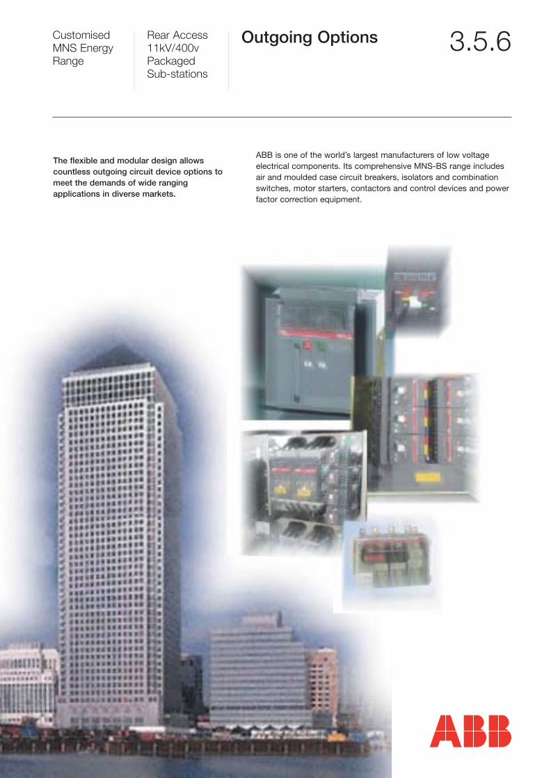
ABB is one of the world’s largest manufacturers of low voltage electrical components. Its comprehensive MNS-BS range includesair and moulded case circuit breakers, isolators and combinationswitches, motor starters, contactors and control devices and powerfactor correction equipment.
The flexible and modular design allows countless outgoing circuit device options tomeet the demands of wide ranging applications in diverse markets.
Air Circuit Breakers 3.5.6aAir Circuit Breakers
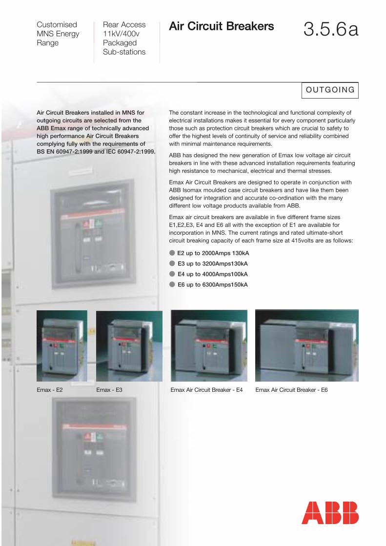
Emax - E2 Emax - E3
The constant increase in the technological and functional complexity of electrical installations makes it essential for every component particularlythose such as protection circuit breakers which are crucial to safety tooffer the highest levels of continuity of service and reliability combinedwith minimal maintenance requirements.
ABB has designed the new generation of Emax low voltage air circuit breakers in line with these advanced installation requirements featuringhigh resistance to mechanical, electrical and thermal stresses.
Emax Air Circuit Breakers are designed to operate in conjunction withABB Isomax moulded case circuit breakers and have like them beendesigned for integration and accurate co-ordination with the many different low voltage products available from ABB.
Emax air circuit breakers are available in five different frame sizesE1,E2,E3, E4 and E6 all with the exception of E1 are available for incorporation in MNS. The current ratings and rated ultimate-short circuit breaking capacity of each frame size at 415volts are as follows:
� E2 up to 2000Amps 130kA
� E3 up to 3200Amps130kA
� E4 up to 4000Amps100kA
� E6 up to 6300Amps150kA
Air Circuit Breakers installed in MNS for outgoing circuits are selected from the ABB Emax range of technically advancedhigh performance Air Circuit Breakers complying fully with the requirements of BS EN 60947-2:1999 and IEC 60947-2:1999.
Emax Air Circuit Breaker - E4 Emax Air Circuit Breaker - E6
OUTGOING
Rear Access11kV/400vPackaged Sub-stations
Customised MNS EnergyRange
Customised MNS EnergyRange
Rear AccessEnergy Centre400V/6300 amps
Air CircuitBreakers -continued
3.5.6b
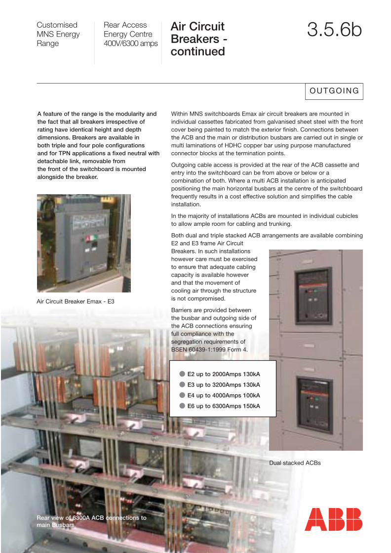
Within MNS switchboards Emax air circuit breakers are mounted in individual cassettes fabricated from galvanised sheet steel with the frontcover being painted to match the exterior finish. Connections betweenthe ACB and the main or distribution busbars are carried out in single ormulti laminations of HDHC copper bar using purpose manufacturedconnector blocks at the termination points.
Outgoing cable access is provided at the rear of the ACB cassette andentry into the switchboard can be from above or below or a combination of both. Where a multi ACB installation is anticipated positioning the main horizontal busbars at the centre of the switchboard frequently results in a cost effective solution and simplifies the cableinstallation.
In the majority of installations ACBs are mounted in individual cubiclesto allow ample room for cabling and trunking.
Both dual and triple stacked ACB arrangements are available combiningE2 and E3 frame Air CircuitBreakers. In such installationshowever care must be exercisedto ensure that adequate cablingcapacity is available howeverand that the movement of cooling air through the structureis not compromised.
Barriers are provided betweenthe busbar and outgoing side ofthe ACB connections ensuringfull compliance with the segregation requirements ofBSEN 60439-1:1999 Form 4.
A feature of the range is the modularity andthe fact that all breakers irrespective of rating have identical height and depthdimensions. Breakers are available in both triple and four pole configurations and for TPN applications a fixed neutral with detachable link, removable from the front of the switchboard is mounted alongside the breaker.
� E2 up to 2000Amps 130kA
� E3 up to 3200Amps 130kA
� E4 up to 4000Amps 100kA
� E6 up to 6300Amps 150kA
OUTGOING
Air Circuit Breaker Emax - E3
Dual stacked ACBs
Rear view of 6300A ACB connections tomain Busbars
Customised MNS EnergyRange
Rear Access11kV/400vPackaged Sub-stations
Moulded CaseCircuit Breakers -Outgoing
3.5.6c
OUTGOING
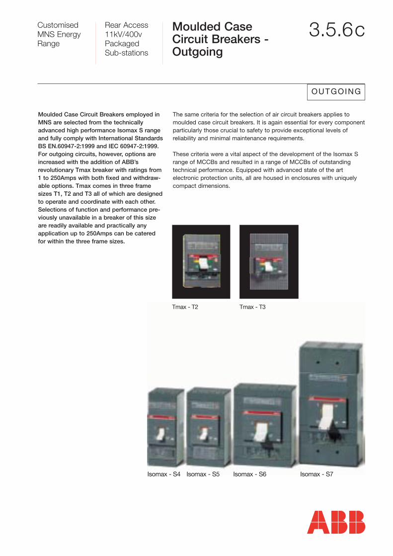
The same criteria for the selection of air circuit breakers applies tomoulded case circuit breakers. It is again essential for every componentparticularly those crucial to safety to provide exceptional levels of reliability and minimal maintenance requirements.
These criteria were a vital aspect of the development of the Isomax Srange of MCCBs and resulted in a range of MCCBs of outstandingtechnical performance. Equipped with advanced state of the art electronic protection units, all are housed in enclosures with uniquelycompact dimensions.
Moulded Case Circuit Breakers employed inMNS are selected from the technicallyadvanced high performance Isomax S rangeand fully comply with International StandardsBS EN.60947-2:1999 and IEC 60947-2:1999.For outgoing circuits, however, options areincreased with the addition of ABB’s revolutionary Tmax breaker with ratings from1 to 250Amps with both fixed and withdraw-able options. Tmax comes in three framesizes T1, T2 and T3 all of which are designedto operate and coordinate with each other.Selections of function and performance pre-viously unavailable in a breaker of this sizeare readily available and practically anyapplication up to 250Amps can be cateredfor within the three frame sizes.
Isomax - S5Isomax - S4
Tmax - T2 Tmax - T3
Isomax - S6 Isomax - S7
Customised MNS EnergyRange
Rear Access11kV/400vPackaged Sub-stations
Moulded CaseCircuit Breakers -continued
3.5.6d
OUTGOING
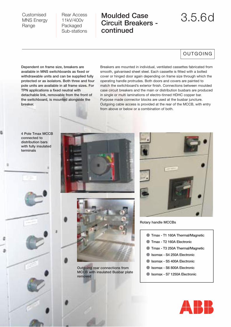
Breakers are mounted in individual, ventilated cassettes fabricated fromsmooth, galvanised sheet steel. Each cassette is fitted with a boltedcover or hinged door again depending on frame size through which theoperating handle protrudes. Both doors and covers are painted tomatch the switchboard’s exterior finish. Connections between mouldedcase circuit breakers and the main or distribution busbars are producedin single or multi laminations of electro-tinned HDHC copper bar.Purpose made connector blocks are used at the busbar juncture.Outgoing cable access is provided at the rear of the MCCB, with entryfrom above or below or a combination of both.
Dependent on frame size, breakers are available in MNS switchboards as fixed orwithdrawable units and can be supplied fullyprotected or as isolators. Both three and fourpole units are available in all frame sizes. ForTPN applications a fixed neutral with detachable link, removable from the front ofthe switchboard, is mounted alongside thebreaker.
Rotary handle MCCBs
Outgoing rear connections fromMCCB with insulated Busbar plateremoved
4 Pole Tmax MCCBconnected to distribution barswith fully insulated terminals
� Tmax - T1 160A Thermal/Magnetic
� Tmax - T2 160A Electronic
� Tmax - T3 250A Thermal/Magnetic
� Isomax - S4 250A Electronic
� Isomax - S5 400A Electronic
� Isomax - S6 800A Electronic
� Isomax - S7 1250A Electronic
Customised MNS EnergyRange
Rear Access11kV/400vPackaged Sub-stations
MCCB BackpanAssemblies 3.5.6e
OUTGOING
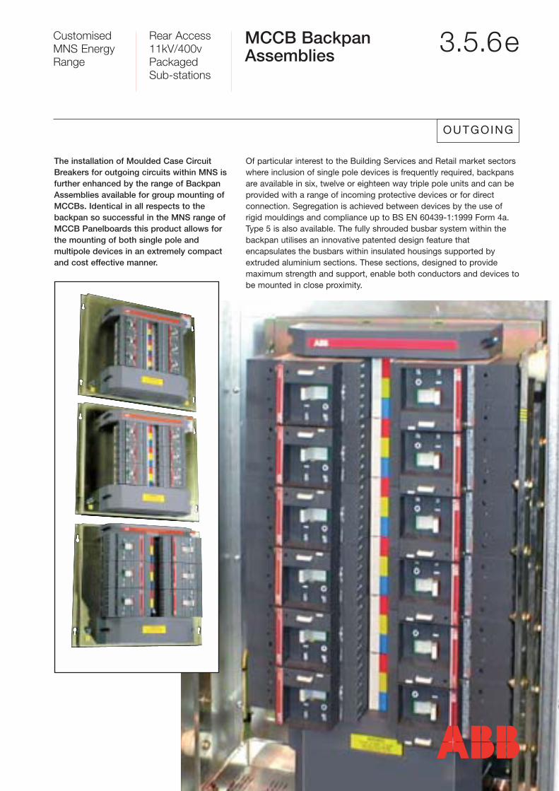
The installation of Moulded Case CircuitBreakers for outgoing circuits within MNS isfurther enhanced by the range of BackpanAssemblies available for group mounting ofMCCBs. Identical in all respects to the backpan so successful in the MNS range ofMCCB Panelboards this product allows forthe mounting of both single pole and multipole devices in an extremely compactand cost effective manner.
Of particular interest to the Building Services and Retail market sectorswhere inclusion of single pole devices is frequently required, backpansare available in six, twelve or eighteen way triple pole units and can beprovided with a range of incoming protective devices or for direct connection. Segregation is achieved between devices by the use ofrigid mouldings and compliance up to BS EN 60439-1:1999 Form 4a.Type 5 is also available. The fully shrouded busbar system within the backpan utilises an innovative patented design feature that encapsulates the busbars within insulated housings supported byextruded aluminium sections. These sections, designed to provide maximum strength and support, enable both conductors and devices tobe mounted in close proximity.
Customised MNS EnergyRange
Rear Access11kV/400vPackaged Sub-stations
MCCB BackpanAssemblies -continued
3.5.6f
OUTGOING
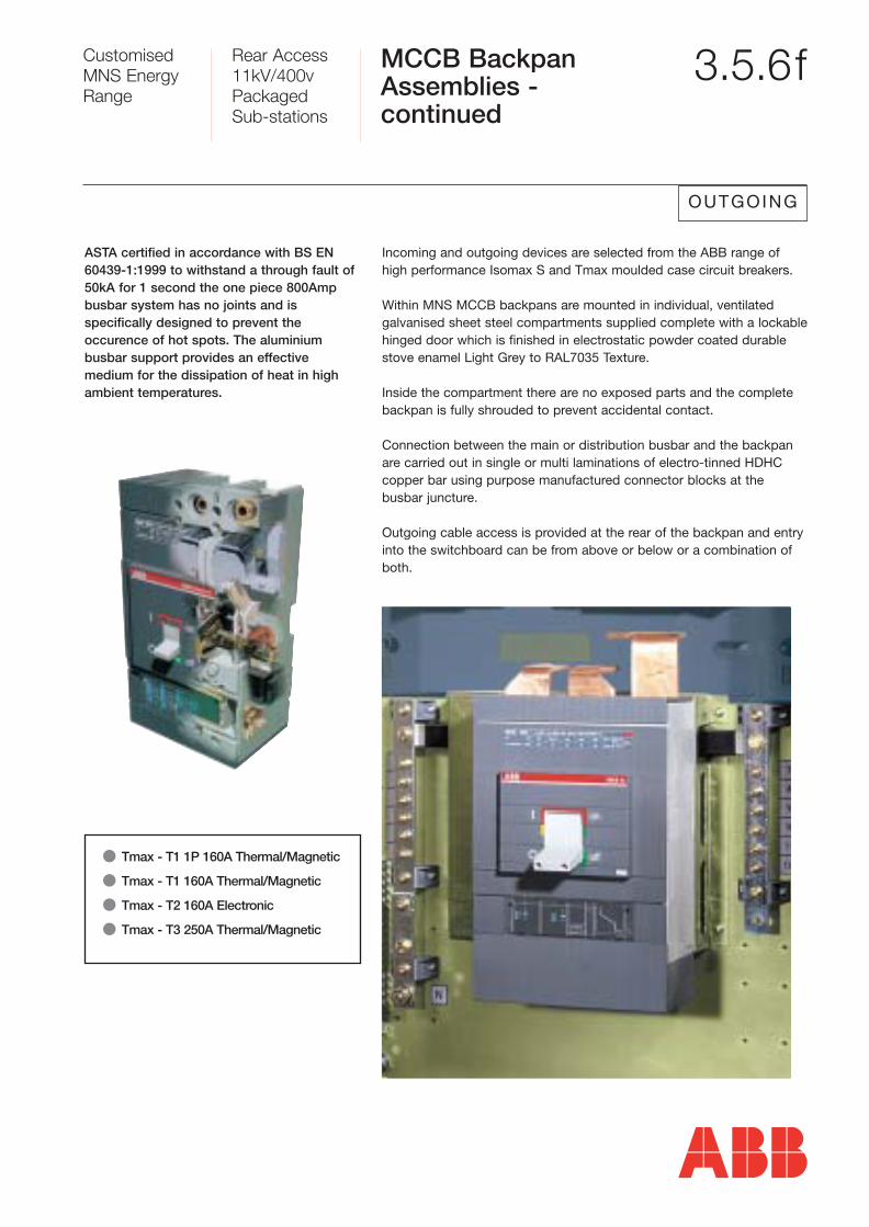
Incoming and outgoing devices are selected from the ABB range ofhigh performance Isomax S and Tmax moulded case circuit breakers.
Within MNS MCCB backpans are mounted in individual, ventilated galvanised sheet steel compartments supplied complete with a lockablehinged door which is finished in electrostatic powder coated durablestove enamel Light Grey to RAL7035 Texture.
Inside the compartment there are no exposed parts and the complete backpan is fully shrouded to prevent accidental contact.
Connection between the main or distribution busbar and the backpanare carried out in single or multi laminations of electro-tinned HDHCcopper bar using purpose manufactured connector blocks at the busbar juncture.
Outgoing cable access is provided at the rear of the backpan and entryinto the switchboard can be from above or below or a combination ofboth.
ASTA certified in accordance with BS EN60439-1:1999 to withstand a through fault of50kA for 1 second the one piece 800Ampbusbar system has no joints and is specifically designed to prevent theoccurence of hot spots. The aluminium busbar support provides an effective medium for the dissipation of heat in highambient temperatures.
� Tmax - T1 1P 160A Thermal/Magnetic
� Tmax - T1 160A Thermal/Magnetic
� Tmax - T2 160A Electronic
� Tmax - T3 250A Thermal/Magnetic
Customised MNS EnergyRange
Rear Access11kV/400vPackaged Sub-stations
CombinationSwitchfuses and Isolators
3.5.6g
OUTGOING
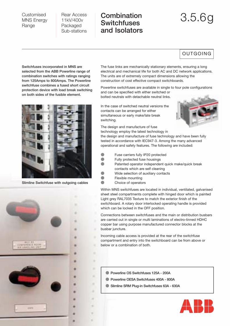
The fuse links are mechanically stationary elements, ensuring a long electrical and mechanical life for both AC and DC network applications. The units are of extremely compact dimensions allowing the construction of cost effective compact switchboards.
Powerline switchfuses are available in single to four pole configurations and can be specified with either switched orbolted neutrals with detachable neutral links.
In the case of switched neutral versions the contacts can be arranged for either simultaneous or early make/late breakswitching.
The design and manufacture of fusetechnology employ the latest technology inthe design and manufacture of fuse technology and have been fullytested in accordance with IEC947-3. Among the many advanced operational and safety features. The following are included:
� Fuse carriers fully IP20 protected� Fully protected fuse housings� Patented operator independent quick make/quick break
contacts which are self cleaning� Wide selection of auxiliary contacts� Flexible mounting� Choice of operators
Within MNS switchfuses are located in individual, ventilated, galvanisedsheet steel compartments complete with hinged door which is paintedLight grey RAL7035 Texture to match the exterior finish of the switchboard. A rotary door interlocked operating handle is providedwhich can be locked in the OFF position.
Connections between switchfuses and the main or distribution busbarsare carried out in single or multi laminations of electro-tinned HDHCcopper bar using purpose manufactured connector blocks at the busbar juncture.
Incoming cable access is provided at the rear of the switchfuse compartment and entry into the switchboard can be from above orbelow or a combination of both.
Switchfuses incorporated in MNS are selected from the ABB Powerline range of combination switches with ratings rangingfrom 125Amps to 800Amps. The Powerlineswitchfuse combines a fused short circuitprotection device with load break switchingon both sides of the fusible element.
� Powerline OS Switchfuses 125A - 200A
� Powerline OESA Switchfuses 400A - 800A
� Slimline SRM Plug-in Switchfuses 63A - 630A
Slimline Switchfuse with outgoing cables
Customised MNS EnergyRange
Rear Access11kV/400vPackaged Sub-stations
Motor Startersand Contactors 3.5.6h
OUTGOING
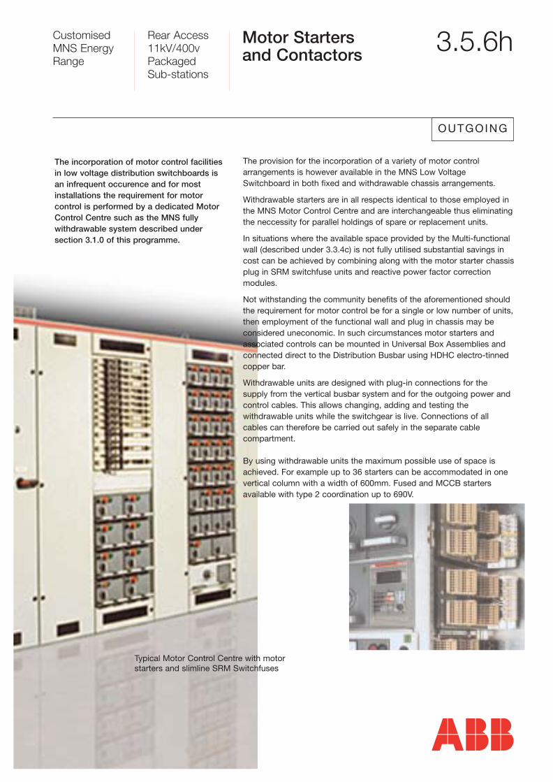
The provision for the incorporation of a variety of motor control arrangements is however available in the MNS Low VoltageSwitchboard in both fixed and withdrawable chassis arrangements.
Withdrawable starters are in all respects identical to those employed inthe MNS Motor Control Centre and are interchangeable thus eliminatingthe neccessity for parallel holdings of spare or replacement units.
In situations where the available space provided by the Multi-functionalwall (described under 3.3.4c) is not fully utilised substantial savings incost can be achieved by combining along with the motor starter chassisplug in SRM switchfuse units and reactive power factor correction modules.
Not withstanding the community benefits of the aforementioned shouldthe requirement for motor control be for a single or low number of units,then employment of the functional wall and plug in chassis may be considered uneconomic. In such circumstances motor starters andassociated controls can be mounted in Universal Box Assemblies andconnected direct to the Distribution Busbar using HDHC electro-tinnedcopper bar.
Withdrawable units are designed with plug-in connections for the supply from the vertical busbar system and for the outgoing power andcontrol cables. This allows changing, adding and testing the withdrawable units while the switchgear is live. Connections of allcables can therefore be carried out safely in the separate cable compartment.
By using withdrawable units the maximum possible use of space isachieved. For example up to 36 starters can be accommodated in onevertical column with a width of 600mm. Fused and MCCB starters available with type 2 coordination up to 690V.
The incorporation of motor control facilitiesin low voltage distribution switchboards isan infrequent occurence and for most installations the requirement for motor control is performed by a dedicated MotorControl Centre such as the MNS fully withdrawable system described under section 3.1.0 of this programme.
Typical Motor Control Centre with motorstarters and slimline SRM Switchfuses
Customised MNS EnergyRange
Rear Access11kV/400vPackaged Sub-stations
Motor Startersand Contactors -continued
3.5.6i
OUTGOING
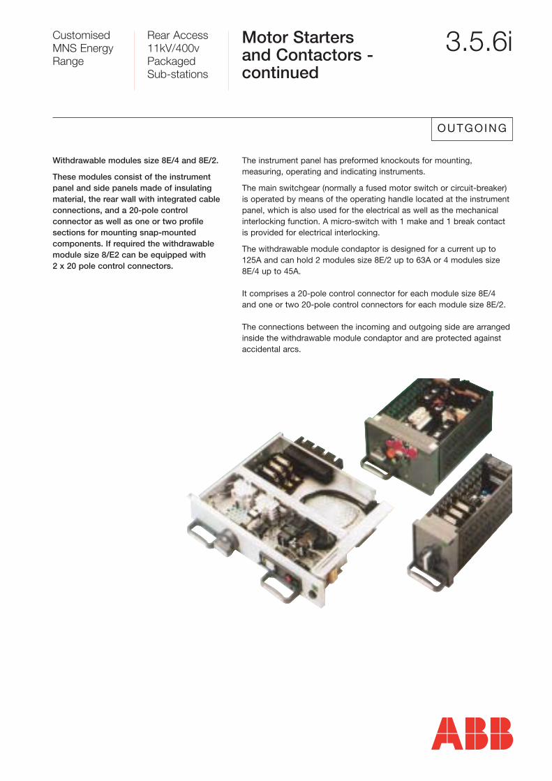
The instrument panel has preformed knockouts for mounting, measuring, operating and indicating instruments.
The main switchgear (normally a fused motor switch or circuit-breaker)is operated by means of the operating handle located at the instrumentpanel, which is also used for the electrical as well as the mechanicalinterlocking function. A micro-switch with 1 make and 1 break contactis provided for electrical interlocking.
The withdrawable module condaptor is designed for a current up to 125A and can hold 2 modules size 8E/2 up to 63A or 4 modules size8E/4 up to 45A.
It comprises a 20-pole control connector for each module size 8E/4 and one or two 20-pole control connectors for each module size 8E/2.
The connections between the incoming and outgoing side are arrangedinside the withdrawable module condaptor and are protected against accidental arcs.
Withdrawable modules size 8E/4 and 8E/2.
These modules consist of the instrumentpanel and side panels made of insulatingmaterial, the rear wall with integrated cableconnections, and a 20-pole control connector as well as one or two profile sections for mounting snap-mounted components. If required the withdrawablemodule size 8/E2 can be equipped with 2 x 20 pole control connectors.
Customised MNS EnergyRange
Rear Access11kV/400vPackaged Sub-stations
Motor Startersand Contactors -continued
3.5.6j
OUTGOING
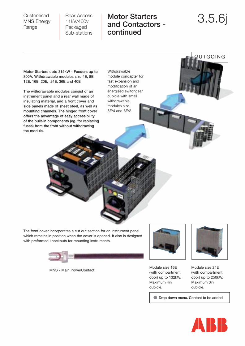
Withdrawable module condapter forfast expansion and modification of anenergised switchgear cubicle with small withdrawable modules size 8E/4 and 8E/2.
Motor Starters upto 315kW - Feeders up to800A. Withdrawable modules size 4E, 8E,12E, 16E, 20E, 24E, 36E and 40E
The withdrawable modules consist of aninstrument panel and a rear wall made ofinsulating material, and a front cover andside panels made of sheet steel, as well asmounting channels. The hinged front coveroffers the advantage of easy accessibility of the built-in components (eg. for replacingfuses) from the front without withdrawing the module.
The front cover incorporates a cut out section for an instrument panel which remains in position when the cover is opened. It also is designedwith preformed knockouts for mounting instruments.
Module size 16E (with compartmentdoor) up to 132kW. Maximum 4in cubicle.
Module size 24E (with compartmentdoor) up to 250kW. Maximum 3in cubicle.
MNS - Main PowerContact
� Drop down menu. Content to be added
Customised MNS EnergyRange
Rear Access11kV/400vPackaged Sub-stations
Power FactorCorrection 3.5.6k
GENERAL
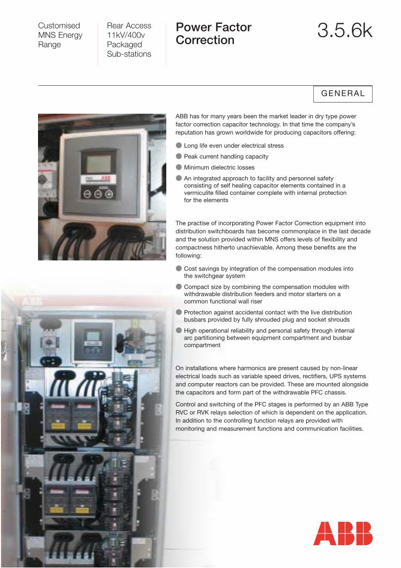
ABB has for many years been the market leader in dry type power factor correction capacitor technology. In that time the company’s reputation has grown worldwide for producing capacitors offering:
� Long life even under electrical stress
� Peak current handling capacity
� Minimum dielectric losses
� An integrated approach to facility and personnel safety consisting of self healing capacitor elements contained in avermiculite filled container complete with internal protection for the elements
The practise of incorporating Power Factor Correction equipment into distribution switchboards has become commonplace in the last decadeand the solution provided within MNS offers levels of flexibility andcompactness hitherto unachievable. Among these benefits are the following:
� Cost savings by integration of the compensation modules into the switchgear system
� Compact size by combining the compensation modules with withdrawable distribution feeders and motor starters on a common functional wall riser
� Protection against accidental contact with the live distribution busbars provided by fully shrouded plug and socket shrouds
� High operational reliability and personal safety through internal arc partitioning between equipment compartment and busbar compartment
On installations where harmonics are present caused by non-linearelectrical loads such as variable speed drives, rectifiers, UPS systemsand computer reactors can be provided. These are mounted alongsidethe capacitors and form part of the withdrawable PFC chassis.
Control and switching of the PFC stages is performed by an ABB TypeRVC or RVK relays selection of which is dependent on the application. In addition to the controlling function relays are provided with monitoring and measurement functions and communication facilities.

Customised MNS EnergyRange
Rear Access11kV/400vPackaged Sub-stations
Universal BoxAssemblies 3.5.6l
GENERAL
In addition to the comprehensive range of modules which housedevices such as moulded case circuit breakers and switchfuses, acomprehensive range of universal box assemblies complete the MNSsystem and is available for the mounting of:
� MCB distribution boards
� instrumentation and meters
� contactors and relays
� fixed pattern motor starters
� control equipment
Each Universal Box assembly includes a hinged door and internalmounting plate, the position of which is adjustable at 50mm intervals toa maximum depth of 310mm. All internal box components are manufactured from smooth galvanised sheet steel. Doors are equippedwith concealed lift off hinges and can be supplied, drilled or punched toaccommodate door mounted equipment such as meters and relays.Exterior finish is durable electro statically applied powder coated paintLight Grey RAL7035 texture. Alternative finishes are available to order at additional cost.
On Universal Boxes up to 600mm wide by 1000mm high (40E) a singledoor is provided which can be hinged on either side. Above this sizeUniversal Boxes are provided with double doors.
Customised MNS EnergyRange
Rear Access11kV/400vPackaged Sub-stations
Busbar System 3.5.5
In developing the MNS range ABB designers were aware that an innovative busbar design was necessary to account for the stressesimposed by ever increasing energy levels being distributed at low voltage while simultaneously providing the flexibility to allow devices tobe easily added or removed. A compact solution enabling the maximumnumber of circuits to be incorporated was also vital in view of therestrictions imposed by architects and specifiers. In the new MNS rangethe busbar system meets all the above criteria. Independent tests byASTA in accordance with BSEN 60439-1: 1999 achieved up to 100kAfor 1 second on main busbars and up to 80kA for 1 second on distribution busbars and risers.
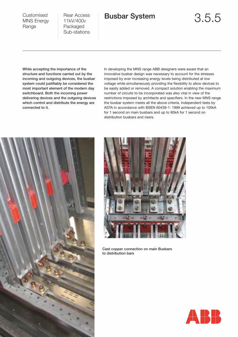
While accepting the importance of the structure and functions carried out by theincoming and outgoing devices, the busbarsystem could justifiably be considered themost important element of the modern dayswitchboard. Both the incoming power delivering devices and the outgoing deviceswhich control and distribute the energy areconnected to it.
Cast copper connection on main Busbarsto distribution bars
Customised MNS EnergyRange
Rear Access11kV/400vPackaged Sub-stations
Main HorizontalBusbars System 3.5.5a
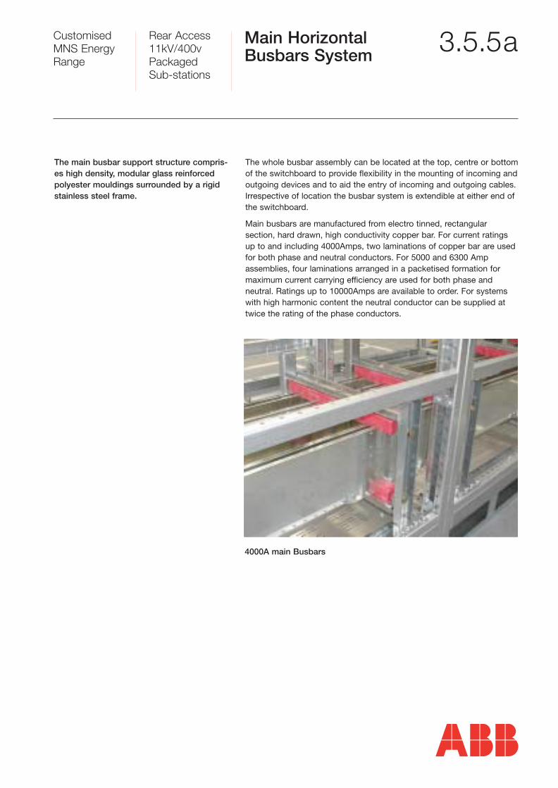
The main busbar support structure compris-es high density, modular glass reinforced polyester mouldings surrounded by a rigidstainless steel frame.
The whole busbar assembly can be located at the top, centre or bottomof the switchboard to provide flexibility in the mounting of incoming and outgoing devices and to aid the entry of incoming and outgoing cables.Irrespective of location the busbar system is extendible at either end ofthe switchboard.
Main busbars are manufactured from electro tinned, rectangular section, hard drawn, high conductivity copper bar. For current ratingsup to and including 4000Amps, two laminations of copper bar are usedfor both phase and neutral conductors. For 5000 and 6300 Amp assemblies, four laminations arranged in a packetised formation formaximum current carrying efficiency are used for both phase and neutral. Ratings up to 10000Amps are available to order. For systemswith high harmonic content the neutral conductor can be supplied attwice the rating of the phase conductors.
4000A main Busbars
Customised MNS EnergyRange
Rear Access11kV/400vPackaged Sub-stations
Main HorizontalBusbars System -continued
3.5.5b
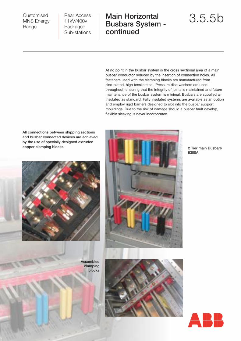
All connections between shipping sectionsand busbar connected devices are achievedby the use of specially designed extrudedcopper clamping blocks.
At no point in the busbar system is the cross sectional area of a mainbusbar conductor reduced by the insertion of connection holes. All fasteners used with the clamping blocks are manufactured from zinc-plated, high tensile steel. Pressure disc washers are used throughout, ensuring that the integrity of joints is maintained and future maintenance of the busbar system is minimal. Busbars are supplied airinsulated as standard. Fully insulated systems are available as an optionand employ rigid barriers designed to slot into the busbar supportmouldings. Due to the risk of damage should a busbar fault develop,flexible sleeving is never incorporated.
2 Tier main Busbars6300A
Assembledclamping
blocks
Customised MNS EnergyRange
Rear Access11kV/400vPackaged Sub-stations
Distribution Busbarsand Risers 3.5.5c
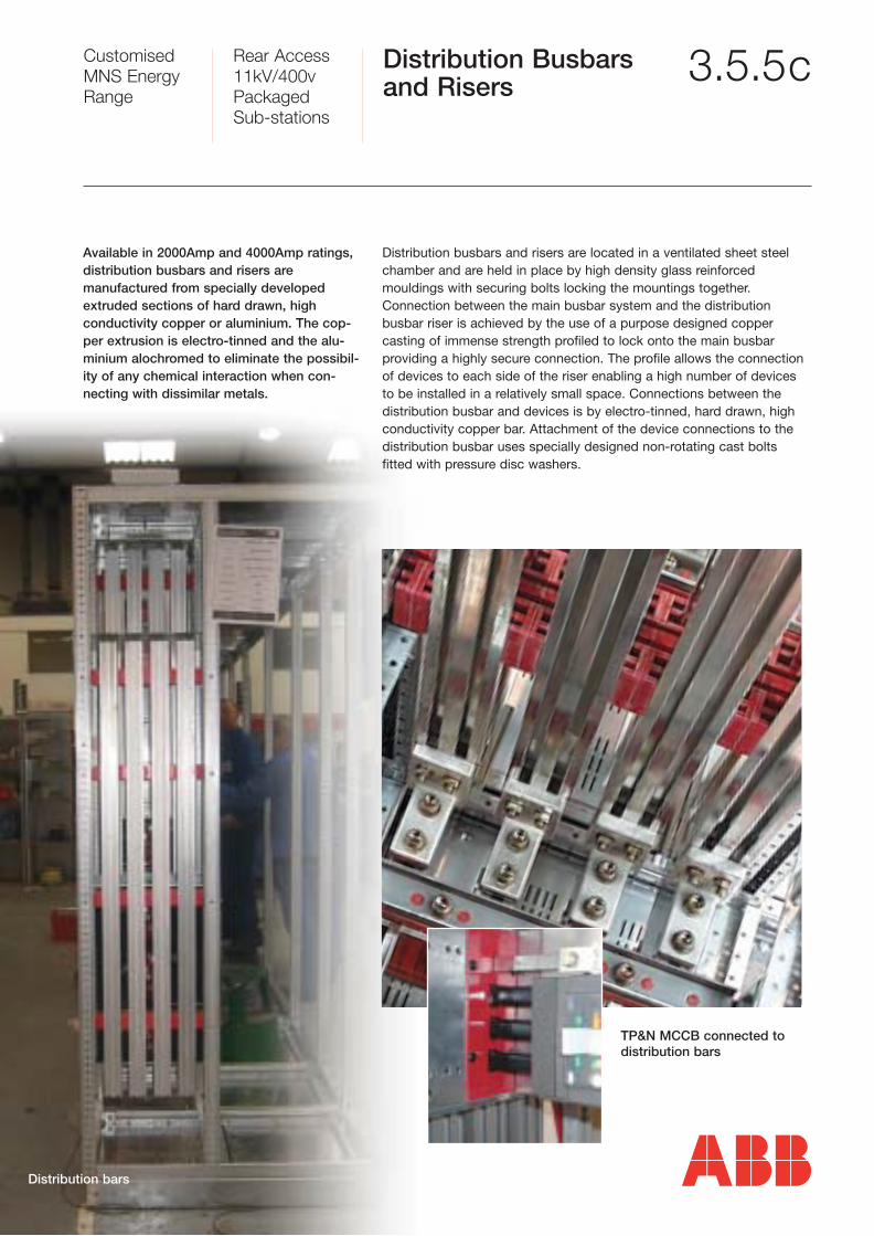
Available in 2000Amp and 4000Amp ratings,distribution busbars and risers are manufactured from specially developedextruded sections of hard drawn, high conductivity copper or aluminium. The cop-per extrusion is electro-tinned and the alu-minium alochromed to eliminate the possibil-ity of any chemical interaction when con-necting with dissimilar metals.
TP&N MCCB connected to distribution bars
Distribution bars
Distribution busbars and risers are located in a ventilated sheet steelchamber and are held in place by high density glass reinforced mouldings with securing bolts locking the mountings together. Connection between the main busbar system and the distribution busbar riser is achieved by the use of a purpose designed copper casting of immense strength profiled to lock onto the main busbar providing a highly secure connection. The profile allows the connectionof devices to each side of the riser enabling a high number of devicesto be installed in a relatively small space. Connections between the distribution busbar and devices is by electro-tinned, hard drawn, highconductivity copper bar. Attachment of the device connections to thedistribution busbar uses specially designed non-rotating cast bolts fitted with pressure disc washers.
Customised MNS EnergyRange
Rear Access11kV/400vPackaged Sub-stations
Multi-Functional Wall 3.5.5d
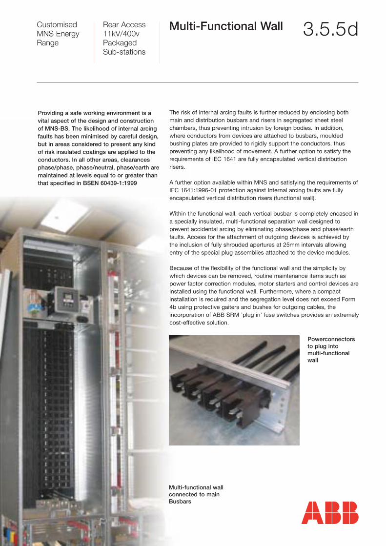
Providing a safe working environment is avital aspect of the design and constructionof MNS-BS. The likelihood of internal arcingfaults has been minimised by careful design,but in areas considered to present any kindof risk insulated coatings are applied to the conductors. In all other areas, clearancesphase/phase, phase/neutral, phase/earth aremaintained at levels equal to or greater thanthat specified in BSEN 60439-1:1999
The risk of internal arcing faults is further reduced by enclosing bothmain and distribution busbars and risers in segregated sheet steelchambers, thus preventing intrusion by foreign bodies. In addition,where conductors from devices are attached to busbars, mouldedbushing plates are provided to rigidly support the conductors, thus preventing any likelihood of movement. A further option to satisfy therequirements of IEC 1641 are fully encapsulated vertical distribution risers.
A further option available within MNS and satisfying the requirements ofIEC 1641:1996-01 protection against Internal arcing faults are fullyencapsulated vertical distribution risers (functional wall).
Within the functional wall, each vertical busbar is completely encased ina specially insulated, multi-functional separation wall designed to prevent accidental arcing by eliminating phase/phase and phase/earthfaults. Access for the attachment of outgoing devices is achieved bythe inclusion of fully shrouded apertures at 25mm intervals allowingentry of the special plug assemblies attached to the device modules.
Because of the flexibility of the functional wall and the simplicity bywhich devices can be removed, routine maintenance items such aspower factor correction modules, motor starters and control devices areinstalled using the functional wall. Furthermore, where a compact installation is required and the segregation level does not exceed Form4b using protective gaiters and bushes for outgoing cables, the incorporation of ABB SRM ’plug in’ fuse switches provides an extremelycost-effective solution.
Powerconnectorsto plug into multi-functionalwall
Multi-functional wallconnected to mainBusbars
Customised MNS EnergyRange
Rear Access11kV/400vPackaged Sub-stations
Incoming Arrangements 3.5.4
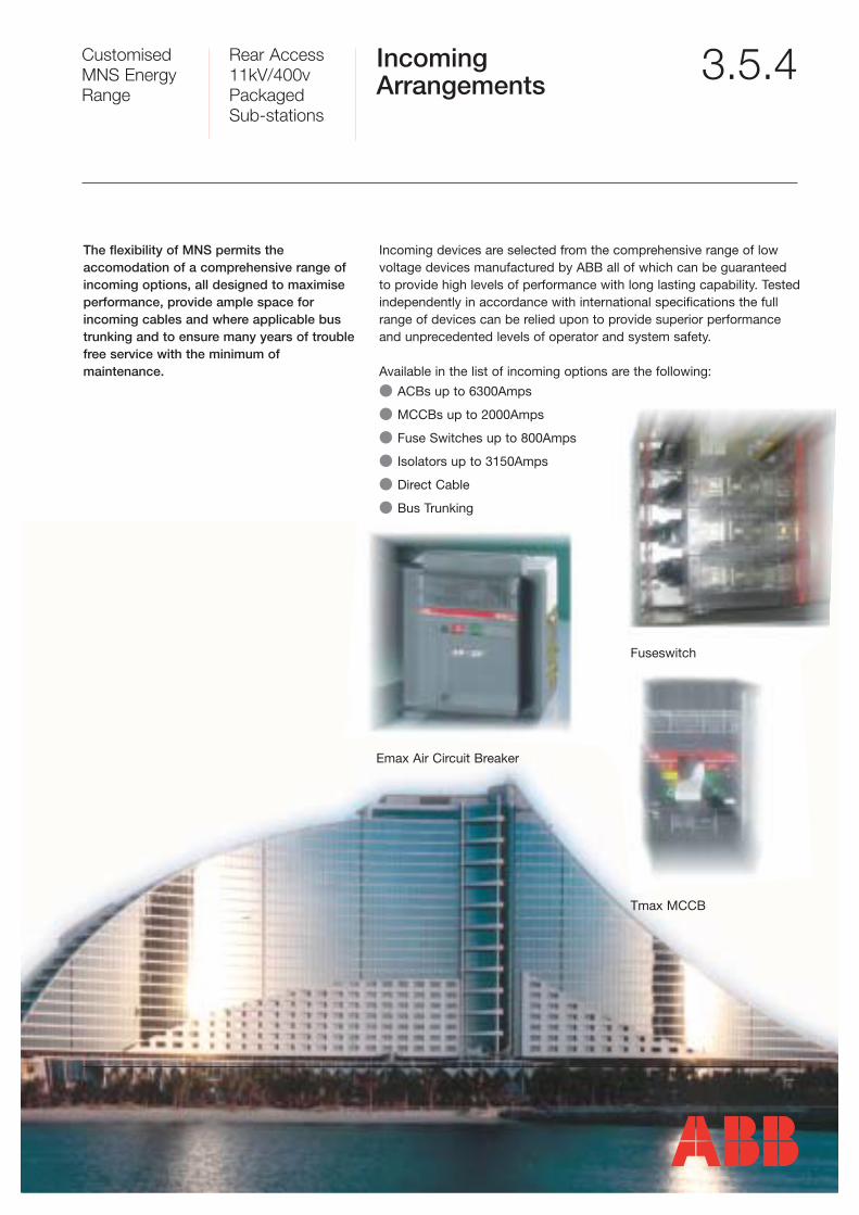
The flexibility of MNS permits the accomodation of a comprehensive range ofincoming options, all designed to maximiseperformance, provide ample space forincoming cables and where applicable bustrunking and to ensure many years of troublefree service with the minimum of maintenance.
Incoming devices are selected from the comprehensive range of lowvoltage devices manufactured by ABB all of which can be guaranteedto provide high levels of performance with long lasting capability. Testedindependently in accordance with international specifications the fullrange of devices can be relied upon to provide superior performanceand unprecedented levels of operator and system safety.
Available in the list of incoming options are the following:
� ACBs up to 6300Amps
� MCCBs up to 2000Amps
� Fuse Switches up to 800Amps
� Isolators up to 3150Amps
� Direct Cable
� Bus Trunking
Fuseswitch
Tmax MCCB
Emax Air Circuit Breaker
Customised MNS EnergyRange
Rear Access11kV/400vPackaged Sub-stations
Air Circuit Breakers 3.5.4a
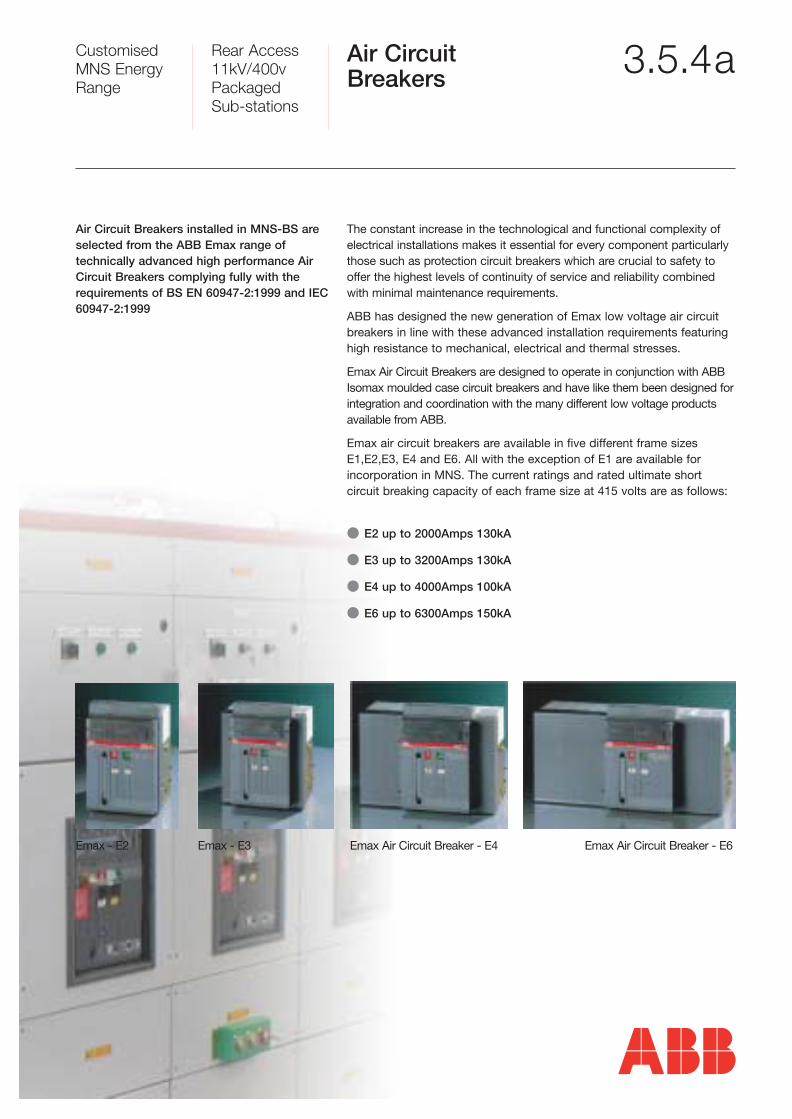
Air Circuit Breakers installed in MNS-BS areselected from the ABB Emax range of technically advanced high performance AirCircuit Breakers complying fully with therequirements of BS EN 60947-2:1999 and IEC60947-2:1999
The constant increase in the technological and functional complexity of electrical installations makes it essential for every component particularlythose such as protection circuit breakers which are crucial to safety tooffer the highest levels of continuity of service and reliability combinedwith minimal maintenance requirements.
ABB has designed the new generation of Emax low voltage air circuit breakers in line with these advanced installation requirements featuringhigh resistance to mechanical, electrical and thermal stresses.
Emax Air Circuit Breakers are designed to operate in conjunction with ABBIsomax moulded case circuit breakers and have like them been designed for integration and coordination with the many different low voltage productsavailable from ABB.
Emax air circuit breakers are available in five different frame sizesE1,E2,E3, E4 and E6. All with the exception of E1 are available forincorporation in MNS. The current ratings and rated ultimate short circuit breaking capacity of each frame size at 415 volts are as follows:
� E2 up to 2000Amps 130kA
� E3 up to 3200Amps 130kA
� E4 up to 4000Amps 100kA
� E6 up to 6300Amps 150kA
Emax - E2 Emax - E3 Emax Air Circuit Breaker - E4 Emax Air Circuit Breaker - E6
Customised MNS EnergyRange
Rear Access11kV/400vPackaged Sub-stations
Air CircuitBreakers - continued 3.5.4b
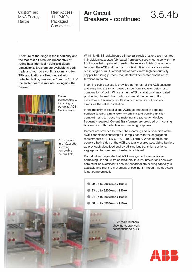
A feature of the range is the modularity andthe fact that all breakers irrespective of rating have identical height and depthdimensions. Breakers are available in bothtriple and four pole configurations and forTPN applications a fixed neutral with detachable link, removable from the front ofthe switchboard is mounted alongside thebreaker.
Within MNS-BS switchboards Emax air circuit breakers are mountedin individual cassettes fabricated from galvanised sheet steel with thefront cover being painted to match the exterior finish. Connectionsbetween the ACB and the main or distribution busbars are carriedout in single or multi laminations of hard drawn high conductivitycopper bar using purpose manufactured connector blocks at the termination points.
Incoming cable access is provided at the rear of the ACB cassetteand entry into the switchboard can be from above or below or acombination of both. Where a multi ACB installation is anticipatedpositioning the main horizontal busbars at the centre of the switchboard frequently results in a cost effective solution and simplifies the cable installation.
In the majority of installations ACBs are mounted in separate cubicles to allow ample room for cabling and trunking and for compartments to house the metering and protection devices frequently required. Current Transformers are provided on incomingbusbars for both protection and metering purposes.
Barriers are provided between the incoming and busbar side of theACB connections ensuring full compliance with the segregation requirements of BSEN 60439-1:1999 Form 4. When used as bus couplers both sides of the ACB are totally segregated. Using barriersas previously described and by utilising bus transition sections, segregation between each busbar is achieved.
Both dual and triple stacked ACB arrangements are availablecombining E2 and E3 frame breakers. In such installations howevercare must be exercised to ensure that adequate cabling capacity isavailable and that the movement of cooling air through the structureis not compromised.
� E2 up to 2000Amps 130kA
� E3 up to 3200Amps 130kA
� E4 up to 4000Amps 100kA
� E6 up to 6300Amps 150kA
Cable connections toincoming or outgoing ACBCopperwork
ACB housed in a ‘Cassette’showing removable neutral link
2 Tier main Busbars showing copperwork connections to ACB
Customised MNS EnergyRange
Rear Access11kV/400vPackaged Sub-stations
Moulded Case Circuit Breakers 3.5.4c
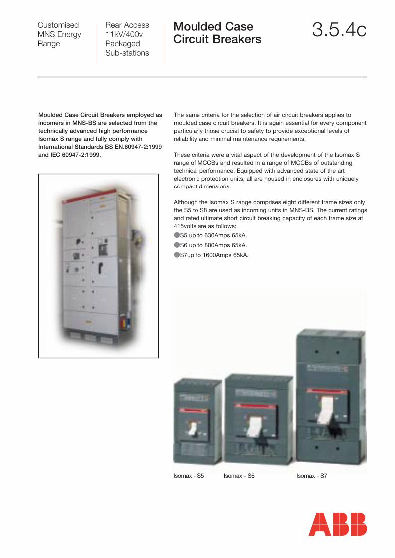
The same criteria for the selection of air circuit breakers applies tomoulded case circuit breakers. It is again essential for every componentparticularly those crucial to safety to provide exceptional levels of reliability and minimal maintenance requirements.
These criteria were a vital aspect of the development of the Isomax Srange of MCCBs and resulted in a range of MCCBs of outstandingtechnical performance. Equipped with advanced state of the art electronic protection units, all are housed in enclosures with uniquelycompact dimensions.
Although the Isomax S range comprises eight different frame sizes onlythe S5 to S8 are used as incoming units in MNS-BS. The current ratingsand rated ultimate short circuit breaking capacity of each frame size at415volts are as follows:
�S5 up to 630Amps 65kA.
�S6 up to 800Amps 65kA.
�S7up to 1600Amps 65kA.
Isomax - S5 Isomax - S6 Isomax - S7
Moulded Case Circuit Breakers employed asincomers in MNS-BS are selected from thetechnically advanced high performanceIsomax S range and fully comply withInternational Standards BS EN.60947-2:1999and IEC 60947-2:1999.
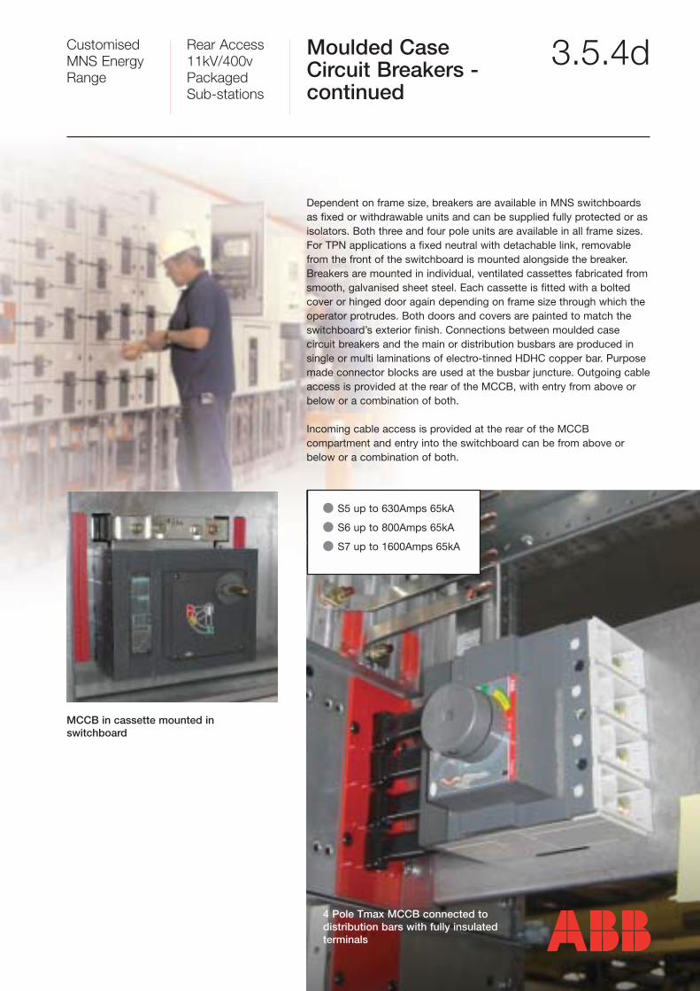
Dependent on frame size, breakers are available in MNS switchboardsas fixed or withdrawable units and can be supplied fully protected or asisolators. Both three and four pole units are available in all frame sizes.For TPN applications a fixed neutral with detachable link, removablefrom the front of the switchboard is mounted alongside the breaker.Breakers are mounted in individual, ventilated cassettes fabricated fromsmooth, galvanised sheet steel. Each cassette is fitted with a boltedcover or hinged door again depending on frame size through which theoperator protrudes. Both doors and covers are painted to match theswitchboard’s exterior finish. Connections between moulded case circuit breakers and the main or distribution busbars are produced insingle or multi laminations of electro-tinned HDHC copper bar. Purposemade connector blocks are used at the busbar juncture. Outgoing cableaccess is provided at the rear of the MCCB, with entry from above orbelow or a combination of both.
Incoming cable access is provided at the rear of the MCCB compartment and entry into the switchboard can be from above orbelow or a combination of both.
� S5 up to 630Amps 65kA
� S6 up to 800Amps 65kA
� S7 up to 1600Amps 65kA
MCCB in cassette mounted in switchboard
4 Pole Tmax MCCB connected to distribution bars with fully insulated terminals
Customised MNS EnergyRange
Rear Access11kV/400vPackaged Sub-stations
Moulded Case Circuit Breakers - continued
3.5.4d
Customised MNS EnergyRange
Rear Access11kV/400vPackaged Sub-stations
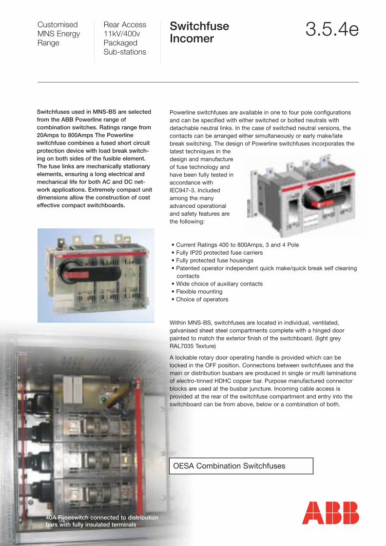
SwitchfuseIncomer 3.5.4e
Powerline switchfuses are available in one to four pole configurationsand can be specified with either switched or bolted neutrals withdetachable neutral links. In the case of switched neutral versions, thecontacts can be arranged either simultaneously or early make/latebreak switching. The design of Powerline switchfuses incorporates thelatest techniques in thedesign and manufactureof fuse technology andhave been fully tested inaccordance withIEC947-3. Includedamong the manyadvanced operationaland safety features arethe following:
• Current Ratings 400 to 800Amps, 3 and 4 Pole• Fully IP20 protected fuse carriers• Fully protected fuse housings• Patented operator independent quick make/quick break self cleaning
contacts• Wide choice of auxiliary contacts• Flexible mounting• Choice of operators
Within MNS-BS, switchfuses are located in individual, ventilated, galvanised sheet steel compartments complete with a hinged doorpainted to match the exterior finish of the switchboard. (light greyRAL7035 Texture)
A lockable rotary door operating handle is provided which can belocked in the OFF position. Connections between switchfuses and themain or distribution busbars are produced in single or multi laminationsof electro-tinned HDHC copper bar. Purpose manufactured connectorblocks are used at the busbar juncture. Incoming cable access is provided at the rear of the switchfuse compartment and entry into theswitchboard can be from above, below or a combination of both.
Switchfuses used in MNS-BS are selectedfrom the ABB Powerline range of combination switches. Ratings range from20Amps to 800Amps The Powerline switchfuse combines a fused short circuitprotection device with load break switch-ing on both sides of the fusible element.The fuse links are mechanically stationary elements, ensuring a long electrical andmechanical life for both AC and DC net-work applications. Extremely compact unitdimensions allow the construction of costeffective compact switchboards.
OESA Combination Switchfuses
40A Fuseswitch connected to distributionbars with fully insulated terminals
Customised MNS EnergyRange
Rear Access11kV/400vPackaged Sub-stations
3.5.3aInternal Sub-divisions
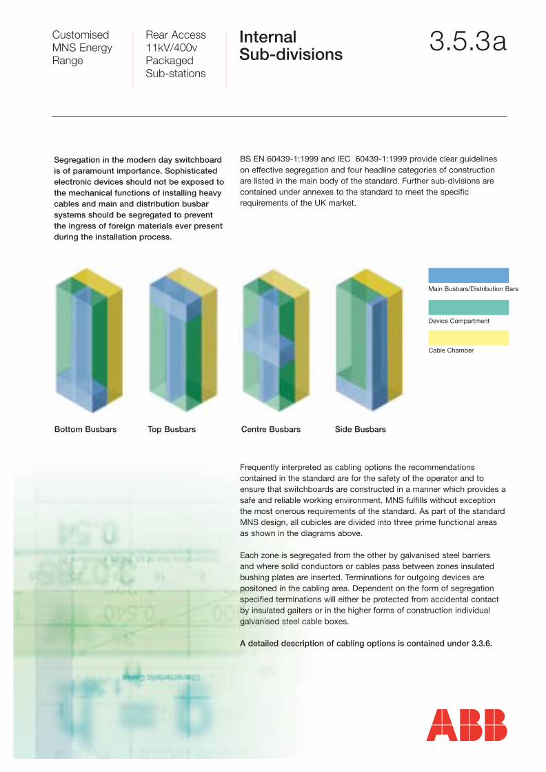
Segregation in the modern day switchboardis of paramount importance. Sophisticatedelectronic devices should not be exposed tothe mechanical functions of installing heavycables and main and distribution busbarsystems should be segregated to preventthe ingress of foreign materials ever presentduring the installation process.
BS EN 60439-1:1999 and IEC 60439-1:1999 provide clear guidelineson effective segregation and four headline categories of constructionare listed in the main body of the standard. Further sub-divisions arecontained under annexes to the standard to meet the specific requirements of the UK market.
Frequently interpreted as cabling options the recommendations contained in the standard are for the safety of the operator and toensure that switchboards are constructed in a manner which provides asafe and reliable working environment. MNS fulfills without exceptionthe most onerous requirements of the standard. As part of the standardMNS design, all cubicles are divided into three prime functional areasas shown in the diagrams above.
Each zone is segregated from the other by galvanised steel barriers and where solid conductors or cables pass between zones insulated bushing plates are inserted. Terminations for outgoing devices are positoned in the cabling area. Dependent on the form of segregationspecified terminations will either be protected from accidental contactby insulated gaiters or in the higher forms of construction individual galvanised steel cable boxes.
A detailed description of cabling options is contained under 3.3.6.
Bottom Busbars Top Busbars Centre Busbars Side Busbars
Main Busbars/Distribution Bars
Device Compartment
Cable Chamber
Customised MNS EnergyRange
Rear Access11kV/400vPackaged Sub-stations
MV Isolators and Ring Main Units 3.5.2
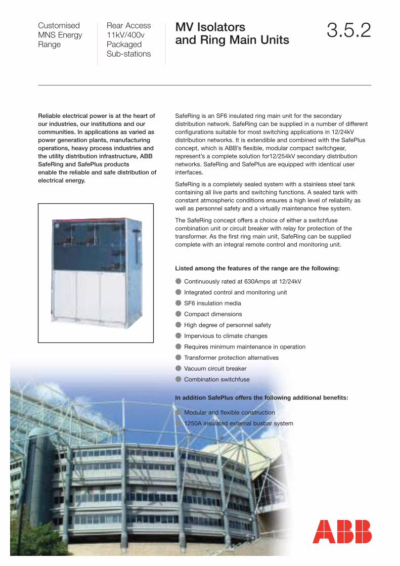
SafeRing is an SF6 insulated ring main unit for the secondary distribution network. SafeRing can be supplied in a number of differentconfigurations suitable for most switching applications in 12/24kV distribution networks. It is extendible and combined with the SafePlusconcept, which is ABB’s flexible, modular compact switchgear, represent’s a complete solution for12/254kV secondary distribution networks. SafeRing and SafePlus are equipped with identical user interfaces.
SafeRing is a completely sealed system with a stainless steel tank containing all live parts and switching functions. A sealed tank withconstant atmospheric conditions ensures a high level of reliability aswell as personnel safety and a virtually maintenance free system.
The SafeRing concept offers a choice of either a switchfuse combination unit or circuit breaker with relay for protection of the transformer. As the first ring main unit, SafeRing can be supplied complete with an integral remote control and monitoring unit.
Listed among the features of the range are the following:
� Continuously rated at 630Amps at 12/24kV
� Integrated control and monitoring unit
� SF6 insulation media
� Compact dimensions
� High degree of personnel safety
� Impervious to climate changes
� Requires minimum maintenance in operation
� Transformer protection alternatives
� Vacuum circuit breaker
� Combination switchfuse
In addition SafePlus offers the following additional benefits:
� Modular and flexible construction
� 1250A insulated external busbar system
Reliable electrical power is at the heart of our industries, our institutions and our communities. In applications as varied aspower generation plants, manufacturing operations, heavy process industries and the utility distribution infrastructure, ABBSafeRing and SafePlus products enable the reliable and safe distribution ofelectrical energy.
Customised MNS EnergyRange
Rear Access11kV/400vPackaged Sub-stations
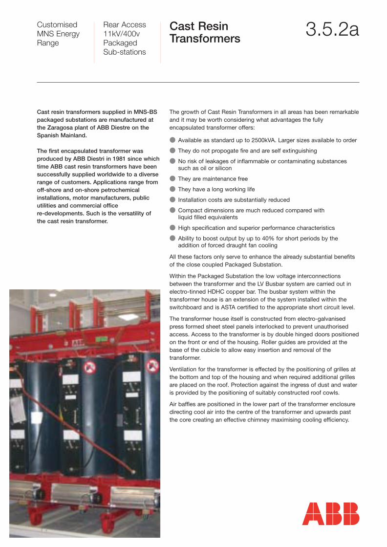
Cast ResinTransformers 3.5.2a
The growth of Cast Resin Transformers in all areas has been remarkable and it may be worth considering what advantages the fully encapsulated transformer offers:
� Available as standard up to 2500kVA. Larger sizes available to order
� They do not propogate fire and are self extinguishing
� No risk of leakages of inflammable or contaminating substances such as oil or silicon
� They are maintenance free
� They have a long working life
� Installation costs are substantially reduced
� Compact dimensions are much reduced compared with liquid filled equivalents
� High specification and superior performance characteristics
� Ability to boost output by up to 40% for short periods by the addition of forced draught fan cooling
All these factors only serve to enhance the already substantial benefitsof the close coupled Packaged Substation.
Within the Packaged Substation the low voltage interconnectionsbetween the transformer and the LV Busbar system are carried out inelectro-tinned HDHC copper bar. The busbar system within the transformer house is an extension of the system installed within theswitchboard and is ASTA certified to the appropriate short circuit level.
The transformer house itself is constructed from electro-galvanisedpress formed sheet steel panels interlocked to prevent unauthorisedaccess. Access to the transformer is by double hinged doors positionedon the front or end of the housing. Roller guides are provided at thebase of the cubicle to allow easy insertion and removal of the transformer.
Ventilation for the transformer is effected by the positioning of grilles atthe bottom and top of the housing and when required additional grilles are placed on the roof. Protection against the ingress of dust and wateris provided by the positioning of suitably constructed roof cowls.
Air baffles are positioned in the lower part of the transformer enclosure directing cool air into the centre of the transformer and upwards pastthe core creating an effective chimney maximising cooling efficiency.
Cast resin transformers supplied in MNS-BSpackaged substations are manufactured atthe Zaragosa plant of ABB Diestre on theSpanish Mainland.
The first encapsulated transformer was produced by ABB Diestri in 1981 since whichtime ABB cast resin transformers have beensuccessfully supplied worldwide to a diverserange of customers. Applications range fromoff-shore and on-shore petrochemical installations, motor manufacturers, public utilities and commercial office re-developments. Such is the versatility ofthe cast resin transformer.
Customised MNS EnergyRange
Rear Access11kV/400vPackaged Sub-stations
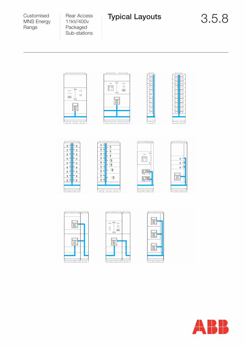
Typical Layouts 3.5.8
0 I
SACE EMAX
SACE EMAX
0 I
METERING
COMPARTMENT
METERING
COMPARTMENT
METERING
COMPARTMENT
METERING
COMPARTMENT
XXXXX
XXXXX
XXXXX
XXXXX
ON
OFF
0 I
SACE EMAX
OFF
O
OFF
O
ON
I
ON
I
OFF
ON
XXXXX
XXXXX
XXXXX
XXXXX
COMPARTMENT
METERING
I0
SACE EMAX
SACE EMAX
I0
SACE EMAX
I0
0 I
SACE EMAX
0 I
SACE EMAX
SACE EMAX
0 I
METERING
COMPARTMENTCOMPARTMENT
METERING