Embed Size (px)
Citation preview
Research Program — Structures and Materials 3.5.1
3.5 Structures and MaterialsGroup leaders: Keith Hjelmstad and Philippe Geubelle
Faculty: Robert Averback, Armand Beaudoin, Robert Dodds, C. Duarte, Philippe Geubelle, Keith Hjelm-stad, Eric Loth, Yonggang Huang, Petros Sofronis, and Daniel Tortorelli
Research Scientists: Karel Matous, Alireza Namazifard, and Henry Tan
Research Programmers: M. Scott Breitenfeld
Post-doctoral Associates: Youhong Li
Graduate Research Assistants: K. Al-Fadhalah, Kristine Cochran (DOE Krell Fellow), Heath Dewey,Morgan Hawker, Mark Gates, Helen Inglis, Rajeev Jaiman, M. Kulkarni, N. Kumar, C. Liu, Justin Mach,S. Meyer, Kalyanbabu Nakshatrala, Praveen Nakshatrala, Henry Padilla, Arun Prakash, K. Srinivasan,Michael Tonks, Daniel Turner, Jay Patel, Brad Roe, Satya Varadhan, Fengbin Xu, Weixing Zhou
Undergraduate Research Assistants: Brett Collins, Jonathan Gu, Steven Stetak, and Jessica Kramer
Overview
The Structures and Materials group is responsible for the analysis of the solid parts of the rocket—therocket case and the unburned solid fuel. The activities of this group divide into two thrust areas: (1) sys-tem simulation and (2) constitutive and failure modeling of components and materials. The technologydeveloped in both of these general areas migrates, when appropriate, to the integrated simulation codes,primarily through the modules Rocsolid and Rocfrac. The research activities in system simulation primar-ily concern the groups led by Professors Dodds, Hjelmstad, and Tortorelli. The research activities in con-stitutive and failure modeling primarily concern the groups led by Professors Averback, Beaudoin,Geubelle, Huang, and Sofronis. In addition to these two key activities, the S&M Team has been involvedin integrated simulations of subscale multiphysics problems such as the convective burning of cracks inenergetic materials and the mesoscale modeling of burning in a damaged solid propellant.
Integrated Simulation Codes for Structural Response
Substantial progress has been made in the further development and integration of the explicit(Rocfrac) and implicit (Rocsolid) structural solvers, which are part of the integrated rocket code.
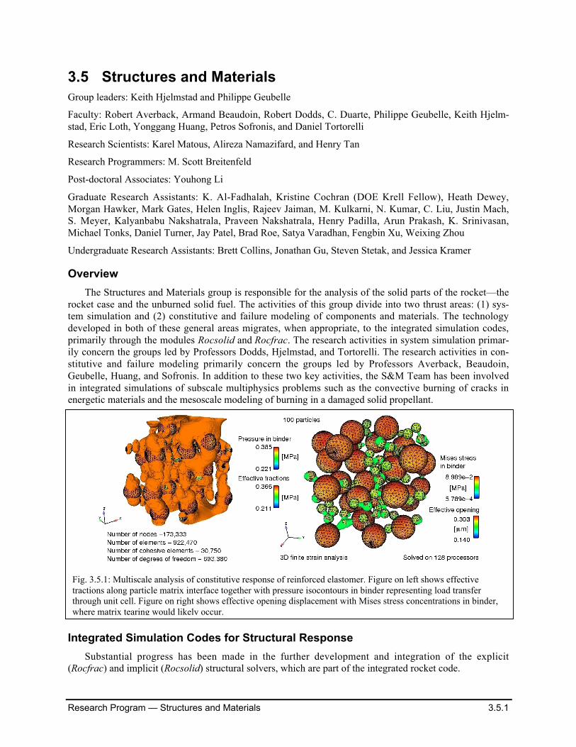
Fig. 3.5.1: Multiscale analysis of constitutive response of reinforced elastomer. Figure on left shows effectivetractions along particle matrix interface together with pressure isocontours in binder representing load transferthrough unit cell. Figure on right shows effective opening displacement with Mises stress concentrations in binder,where matrix tearing would likely occur.
Research Program — Structures and Materials 3.5.2
Rocsolid (Namazifard)
One of the required components in simulating solid rocket motors is computing the structural re-sponse of the propellant, case, liner and nozzle. Our parallel structural analysis code Rocsolid, employs afinite element discretization of the problem domain usingunstructured meshes. Dynamic problems are solved usingthe implicit Newmark time integrator. The linear matrixequations encountered within the Newton iterations ateach time step are solved using a scalable parallel multi-grid solver. The case of the rocket is modeled by usingenhanced assumed strain solid elements. The regressionof the propellant is implemented by using an arbitraryLagrangian-Eulerian (ALE) approach in which the meshmoves to allow for the dynamically changing geometry.The code is written in Fortran90, and uses MPI to per-form interprocessor communications.
Large deformations are formulated using strains-stresses and their rates defined on an unrotated frame ofreference. This model predicts physically acceptable re-sponses for homogeneous deformations of exceedinglylarge magnitude. The implemented numerical algorithm is suitable for the large strain increments, whichmay arise in the implicit solution of the global equilibrium equations, employed in Rocsolid. The finiterotation effects on strain-stress rates are separated from integration of the rates to update the material re-sponse over a time step. This formulation is also adopted in large-scale finite element codes, includingNIKE, Abaqus-Standard, and Abaqus-Explicit.
Rocsolid features nonlinear composite constitutive models to predict damage evolution in solid pro-pellant. Three different constitutive models for solid propellant materials are available in Rocsolid. Thefirst model describes a porous viscoelastic material, i.e., the effect of damage-induced porosity on theconstitutive behavior of a solid propellant. The presence ofporosity is considered to be a result of complete particledewetting. The material model is developed by considering aunit cell containing a spherical void under macroscopic axi-symmetric stressing. In view of the complexity of the calcu-lations, the pure matrix material is assumed to be describedby the standard isotropic linear viscoelastic model. Themodel is based on small strain formulation. Using the corre-spondence principle of linear viscoelasticity, a constitutivepotential is devised for the response of the porous medium inthe transformed domain. By inverting the associated consti-tutive equation from the Laplace transform domain, the time-dependent response of the porous medium under time-dependent loads is established.
The latest version of Rocsolid includes a mechanism-based constitutive model using state-of-the-art homogeniza-tion procedures for nonlinear composites and strain hardening formulation. The model accounts for theevolution of the microstructure upon straining as is demonstrated by void formation and growth. Since themodel addresses the underlying material deformation mechanisms, the model parameters can be deter-mined experimentally. Using this model, the prediction that there are three regimes of deformation for atypical solid propellant material, namely linear, hardening, and softening agrees well with experiment.
0
0.05
0.1
0.15
0.2
0.25
0.3
0.35
0.4
0.45
0.5
0 0.2 0.4 0.6 0.8 1
Time (sec)
No
rmalize
d d
isp
lace
men
t (u
/L)
ABAQUSRocsolid
( )F N
3.0E6
(sec)t 1.0
F
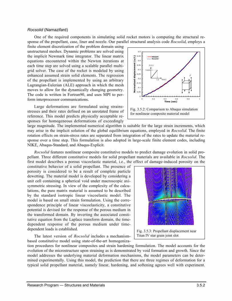
Fig. 3.5.2: Comparison to Abaqus simulationfor nonlinear composite material model
Fig. 3.5.3: Propellant displacement nearTitan IV star grain joint slot
Research Program — Structures and Materials 3.5.3
Also in qualitative agreement with the experiment is the dependence of the response on the strain rate.This model is an improvement for an earlier version, which was based on time hardening formulation.
Verification of the Material Models Implementation
The solid propellant material models were originally implemented and tested in Abaqus through“User Material” subroutines. In order to verify the numerical procedures in Rocsolid and test the imple-mentation of these constitutive models, results are compared for a uniaxial tension problem. Figure 3.5.2shows the displacements computed by Rocsolid and Abaqus using the nonlinear composite materialmodel (with strain hardening formulation). The results are in complete agreement through out the solutionof uniaxial tension test problem.
Application to Titan IV Slumping Problem
The damage constitutive models available in Rocsolid were used to simulate Titan IV SRMU PQM-1slumping problem. The generated mesh for this rocket motor consisted of 1.8 million elements. A coupledfluid-structure-combustion simulation was performed, where the solid propellant was modeled using anonlinear composite material model and the predictor-corrector iterations were employed to enhance thestability of the coupling algorithm. Figure 3.5.3 shows the computed displacement near the star grain jointslot.
Other Enhancements to Rocsolid
Other new enhancements to Rocsolid include development of a 10-node tetrahedral element su p-porting large deformations analysis with all the current material models. Patran can now be used for tetra-hedral mesh generation together with Rocsolid Preptool to prepare necessary input files. Mesh partition-ing is done by Metis for multi-processor computations.
P. Nakshatrala, K. Nakshatrala,Hjelmstad and Namazifard continue towork on the fluid-solid interactionproblem. Our constraint that the fluidcode can only utilize Direchlet bound-ary conditions have hampered our ef-forts. Nonetheless, we believe that wehave developed a promising algorithmthat is suitable for the problem at hand.It relies on the minimization of themomentum flux difference across thefluid-solid interface. We have imple-mented the algorithm for the heat con-duction problem in a fully uncoupledstaggered approach and are currentlystudying its consistency and conver-gence characteristics. Once this study iscompleted we will test the algorithm ina 1-D fluid-solid simulation.
Tonks, Besudoin and Namazifardare investigating the effects of random-ness in polycrystal plasticity simula-tions. By adding a small amount of ran-domness to the uniform velocity gradi-ent that is used in the Taylor model, we are able to produce results that are observed in laboratory experi-
Time (sec)
Stress(MPa)
0 500 1000 1500 2000 2500 30000
0.1
0.2
0.3
0.4
Model predictionExperimental data
Strain rate: 0.25/0.0/0.25/0.0 (1/min)
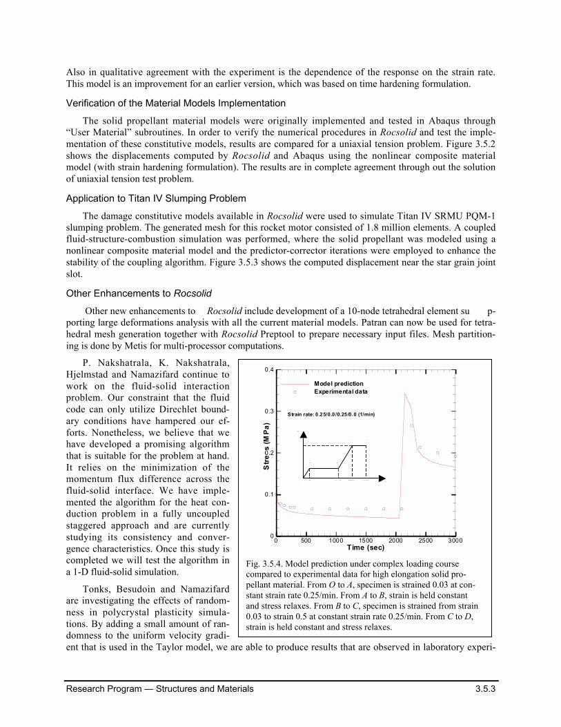
Fig. 3.5.4. Model prediction under complex loading coursecompared to experimental data for high elongation solid pro-pellant material. From O to A, specimen is strained 0.03 at con-stant strain rate 0.25/min. From A to B, strain is held constantand stress relaxes. From B to C, specimen is strained from strain0.03 to strain 0.5 at constant strain rate 0.25/min. From C to D,strain is held constant and stress relaxes.
A B
E
O72. 2092 2205 3000
003.
05.
00.
C D
Time(sec)
Research Program — Structures and Materials 3.5.4
ments, e.g. we do not obtain tumblingsolutions which imply the crystals end-lessly rotate, rather the crystal rotatonsin our simulations are dampened, eventu-ally defining a steady-state texture. Suchfindings are consistent with costly mul-tiscale finite element computations. Cur-rently, we are investigating the effects ofthe randomess on the response and theuse of the Kuramoto model to better ex-plain our response.
Rocsolid Implementation of Constitu-tive Modeling and Fracture (Xu,Aravas, Sofronis)
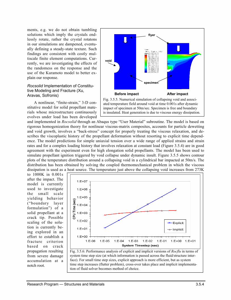
A nonlinear, “finite-strain,” 3-D con-stitutive model for solid propellant mate-rials whose microstructure continuouslyevolves under load has been developedand implemented in Rocsolid through an Abaqus type “User Material” subroutine. The model is based onrigorous homogenization theory for nonlinear viscous-matrix composites, accounts for particle dewettingand void growth, involves a “back-stress” concept for properly treating the viscous relaxation, and de-scribes the viscoplastic history of the propellant deformation without resorting to explicit time depend-ence. The model predictions for simple uniaxial tension over a wide range of applied strains and strainrates and for a complex loading history that involves relaxation at constant load (Figure 3.5.4) are in goodagreement with the experiment even for high elongation solid propellants. The model has been used tosimulate propellant ignition triggered by void collapse under dynamic insult. Figure 3.5.5 shows contourplots of the temperature distribution around a collapsing void in a cylindrical bar impacted at 50m/s. Thedistribution has been obtained by solving the coupled thermomechanical problem in which the viscousdissipation is used as a heat source. The temperature just above the collapsing void increases from 273Kto 1000K in 0.001safter the impact. Themodel is currentlyused to investigatethe small scaleyielding behavior(“boundary layerformulation”) of asolid propellant at acrack tip. Possiblescaling of the solu-tion is currently be-ing explored in aneffort to establish afracture criterionbased on crackpropagation resultingfrom severe damageaccumulation at anotch root.
Fig. 3.5.6: Performance analysis of explicit and implicit versions of Rocflu in terms ofsystem time step size (at which information is passed across the fluid/structure inter-face). For small time step sizes, explicit approach is more efficient, but as systemtime step increases (flutter problem), cross-over takes place and implicit implementa-tion of fluid solver becomes method of choice.
void
flyer
specimen
Before impact After impact
Fig. 3.5.5. Numerical simulation of collapsing void and associ-ated temperature field around void at time 0.001s after dynamicimpact of specimen at 50m/sec. Specimen is free and boundaryis insulated. Heat generation is due to viscous energy dissipation.
Research Program — Structures and Materials 3.5.5
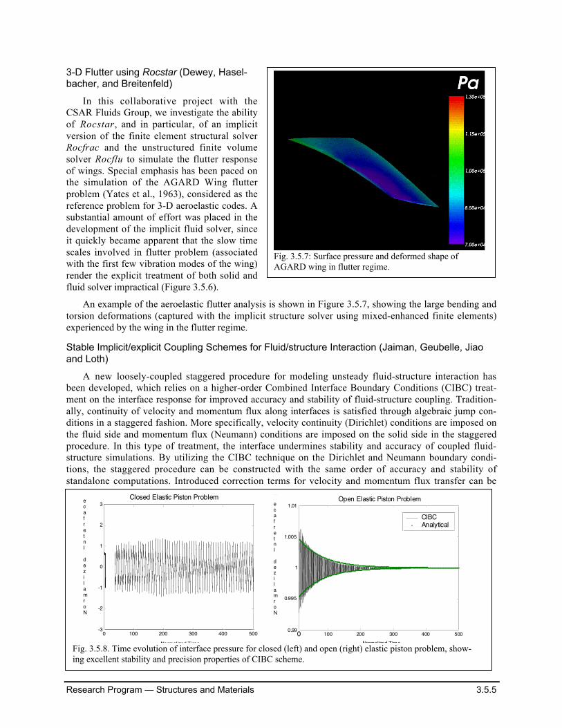
3-D Flutter using Rocstar (Dewey, Hasel-bacher, and Breitenfeld)
In this collaborative project with theCSAR Fluids Group, we investigate the abilityof Rocstar, and in particular, of an implicitversion of the finite element structural solverRocfrac and the unstructured finite volumesolver Rocflu to simulate the flutter responseof wings. Special emphasis has been paced onthe simulation of the AGARD Wing flutterproblem (Yates et al., 1963), considered as thereference problem for 3-D aeroelastic codes. Asubstantial amount of effort was placed in thedevelopment of the implicit fluid solver, sinceit quickly became apparent that the slow timescales involved in flutter problem (associatedwith the first few vibration modes of the wing)render the explicit treatment of both solid andfluid solver impractical (Figure 3.5.6).
An example of the aeroelastic flutter analysis is shown in Figure 3.5.7, showing the large bending andtorsion deformations (captured with the implicit structure solver using mixed-enhanced finite elements)experienced by the wing in the flutter regime.
Stable Implicit/explicit Coupling Schemes for Fluid/structure Interaction (Jaiman, Geubelle, Jiaoand Loth)
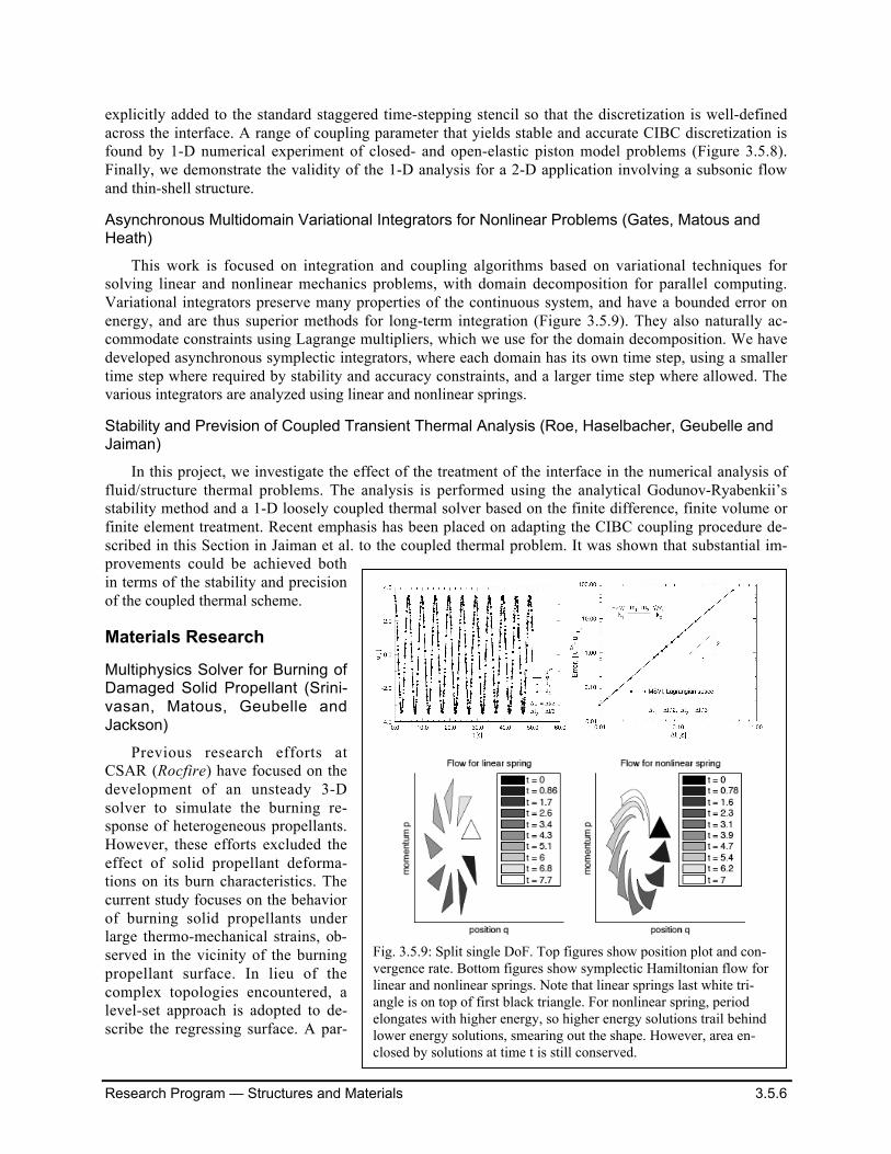
A new loosely-coupled staggered procedure for modeling unsteady fluid-structure interaction hasbeen developed, which relies on a higher-order Combined Interface Boundary Conditions (CIBC) treat-ment on the interface response for improved accuracy and stability of fluid-structure coupling. Tradition-ally, continuity of velocity and momentum flux along interfaces is satisfied through algebraic jump con-ditions in a staggered fashion. More specifically, velocity continuity (Dirichlet) conditions are imposed onthe fluid side and momentum flux (Neumann) conditions are imposed on the solid side in the staggeredprocedure. In this type of treatment, the interface undermines stability and accuracy of coupled fluid-structure simulations. By utilizing the CIBC technique on the Dirichlet and Neumann boundary condi-tions, the staggered procedure can be constructed with the same order of accuracy and stability ofstandalone computations. Introduced correction terms for velocity and momentum flux transfer can be
0 100 200 300 400 500-3
-2
-1
0
1
2
3Closed Elastic Piston Problem
Normalized Time
Normalized Interface Displacement
100 200 300 400 5000.99
0.995
1
1.005
1.01Open Elastic Piston Problem
CIBC Analytical
Normalized Interface Mometum Flux
0 Normalized Time
Fig. 3.5.8. Time evolution of interface pressure for closed (left) and open (right) elastic piston problem, show-ing excellent stability and precision properties of CIBC scheme.
Fig. 3.5.7: Surface pressure and deformed shape ofAGARD wing in flutter regime.
Research Program — Structures and Materials 3.5.6
explicitly added to the standard staggered time-stepping stencil so that the discretization is well-definedacross the interface. A range of coupling parameter that yields stable and accurate CIBC discretization isfound by 1-D numerical experiment of closed- and open-elastic piston model problems (Figure 3.5.8).Finally, we demonstrate the validity of the 1-D analysis for a 2-D application involving a subsonic flowand thin-shell structure.
Asynchronous Multidomain Variational Integrators for Nonlinear Problems (Gates, Matous andHeath)
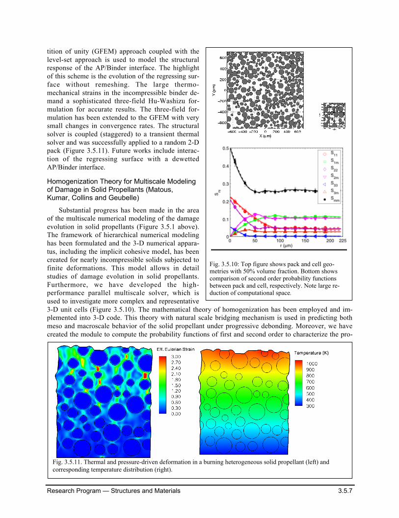
This work is focused on integration and coupling algorithms based on variational techniques forsolving linear and nonlinear mechanics problems, with domain decomposition for parallel computing.Variational integrators preserve many properties of the continuous system, and have a bounded error onenergy, and are thus superior methods for long-term integration (Figure 3.5.9). They also naturally ac-commodate constraints using Lagrange multipliers, which we use for the domain decomposition. We havedeveloped asynchronous symplectic integrators, where each domain has its own time step, using a smallertime step where required by stability and accuracy constraints, and a larger time step where allowed. Thevarious integrators are analyzed using linear and nonlinear springs.
Stability and Prevision of Coupled Transient Thermal Analysis (Roe, Haselbacher, Geubelle andJaiman)
In this project, we investigate the effect of the treatment of the interface in the numerical analysis offluid/structure thermal problems. The analysis is performed using the analytical Godunov-Ryabenkii’sstability method and a 1-D loosely coupled thermal solver based on the finite difference, finite volume orfinite element treatment. Recent emphasis has been placed on adapting the CIBC coupling procedure de-scribed in this Section in Jaiman et al. to the coupled thermal problem. It was shown that substantial im-provements could be achieved bothin terms of the stability and precisionof the coupled thermal scheme.
Materials Research
Multiphysics Solver for Burning ofDamaged Solid Propellant (Srini-vasan, Matous, Geubelle andJackson)
Previous research efforts atCSAR (Rocfire) have focused on thedevelopment of an unsteady 3-Dsolver to simulate the burning re-sponse of heterogeneous propellants.However, these efforts excluded theeffect of solid propellant deforma-tions on its burn characteristics. Thecurrent study focuses on the behaviorof burning solid propellants underlarge thermo-mechanical strains, ob-served in the vicinity of the burningpropellant surface. In lieu of thecomplex topologies encountered, alevel-set approach is adopted to de-scribe the regressing surface. A par-
Fig. 3.5.9: Split single DoF. Top figures show position plot and con-vergence rate. Bottom figures show symplectic Hamiltonian flow forlinear and nonlinear springs. Note that linear springs last white tri-angle is on top of first black triangle. For nonlinear spring, periodelongates with higher energy, so higher energy solutions trail behindlower energy solutions, smearing out the shape. However, area en-closed by solutions at time t is still conserved.
Research Program — Structures and Materials 3.5.7
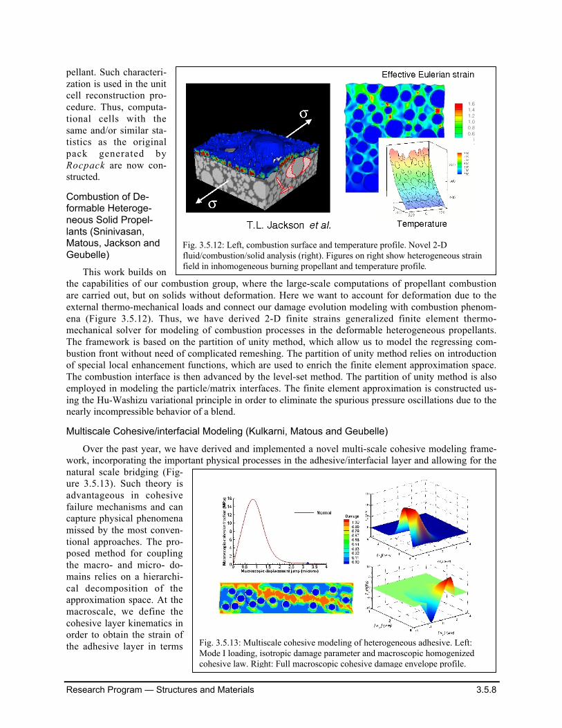
tition of unity (GFEM) approach coupled with thelevel-set approach is used to model the structuralresponse of the AP/Binder interface. The highlightof this scheme is the evolution of the regressing sur-face without remeshing. The large thermo-mechanical strains in the incompressible binder de-mand a sophisticated three-field Hu-Washizu for-mulation for accurate results. The three-field for-mulation has been extended to the GFEM with verysmall changes in convergence rates. The structuralsolver is coupled (staggered) to a transient thermalsolver and was successfully applied to a random 2-Dpack (Figure 3.5.11). Future works include interac-tion of the regressing surface with a dewettedAP/Binder interface.
Homogenization Theory for Multiscale Modelingof Damage in Solid Propellants (Matous,Kumar, Collins and Geubelle)
Substantial progress has been made in the areaof the multiscale numerical modeling of the damageevolution in solid propellants (Figure 3.5.1 above).The framework of hierarchical numerical modelinghas been formulated and the 3-D numerical appara-tus, including the implicit cohesive model, has beencreated for nearly incompressible solids subjected tofinite deformations. This model allows in detailstudies of damage evolution in solid propellants.Furthermore, we have developed the high-performance parallel multiscale solver, which isused to investigate more complex and representative3-D unit cells (Figure 3.5.10). The mathematical theory of homogenization has been employed and im-plemented into 3-D code. This theory with natural scale bridging mechanism is used in predicting bothmeso and macroscale behavior of the solid propellant under progressive debonding. Moreover, we havecreated the module to compute the probability functions of first and second order to characterize the pro-
Fig. 3.5.11. Thermal and pressure-driven deformation in a burning heterogeneous solid propellant (left) andcorresponding temperature distribution (right).
Fig. 3.5.10: Top figure shows pack and cell geo-metries with 50% volume fraction. Bottom showscomparison of second order probability functionsbetween pack and cell, respectively. Note large re-duction of computational space.
Research Program — Structures and Materials 3.5.8
pellant. Such characteri-zation is used in the unitcell reconstruction pro-cedure. Thus, computa-tional cells with thesame and/or similar sta-tistics as the originalpack generated byRocpack are now con-structed.
Combustion of De-formable Heteroge-neous Solid Propel-lants (Sninivasan,Matous, Jackson andGeubelle)
This work builds onthe capabilities of our combustion group, where the large-scale computations of propellant combustionare carried out, but on solids without deformation. Here we want to account for deformation due to theexternal thermo-mechanical loads and connect our damage evolution modeling with combustion phenom-ena (Figure 3.5.12). Thus, we have derived 2-D finite strains generalized finite element thermo-mechanical solver for modeling of combustion processes in the deformable heterogeneous propellants.The framework is based on the partition of unity method, which allow us to model the regressing com-bustion front without need of complicated remeshing. The partition of unity method relies on introductionof special local enhancement functions, which are used to enrich the finite element approximation space.The combustion interface is then advanced by the level-set method. The partition of unity method is alsoemployed in modeling the particle/matrix interfaces. The finite element approximation is constructed us-ing the Hu-Washizu variational principle in order to eliminate the spurious pressure oscillations due to thenearly incompressible behavior of a blend.
Multiscale Cohesive/interfacial Modeling (Kulkarni, Matous and Geubelle)
Over the past year, we have derived and implemented a novel multi-scale cohesive modeling frame-work, incorporating the important physical processes in the adhesive/interfacial layer and allowing for thenatural scale bridging (Fig-ure 3.5.13). Such theory isadvantageous in cohesivefailure mechanisms and cancapture physical phenomenamissed by the most conven-tional approaches. The pro-posed method for couplingthe macro- and micro- do-mains relies on a hierarchi-cal decomposition of theapproximation space. At themacroscale, we define thecohesive layer kinematics inorder to obtain the strain ofthe adhesive layer in terms
Fig. 3.5.12: Left, combustion surface and temperature profile. Novel 2-Dfluid/combustion/solid analysis (right). Figures on right show heterogeneous strainfield in inhomogeneous burning propellant and temperature profile.
Fig. 3.5.13: Multiscale cohesive modeling of heterogeneous adhesive. Left:Mode I loading, isotropic damage parameter and macroscopic homogenizedcohesive law. Right: Full macroscopic cohesive damage envelope profile.
Research Program — Structures and Materials 3.5.9
of the displacement jump, across the cohesive faces. The material periodicity is assumed in the disconti-nuity plane and an asymptotic expansion is employed, whereas the intrinsic cohesive length scale, definedby the layer thickness, is introduced and the space dimension reduction is performed perpendicular to theinterface. The macroscopic displacement jump across the adhesive layer is then used as a forcing term inorder to derive the homogenized cohesive traction-separation law used at the macro-scale. This frame-work is very advantageous in modeling the heterogeneous insulation layer, for example, and allows foraccurate mode mixity.
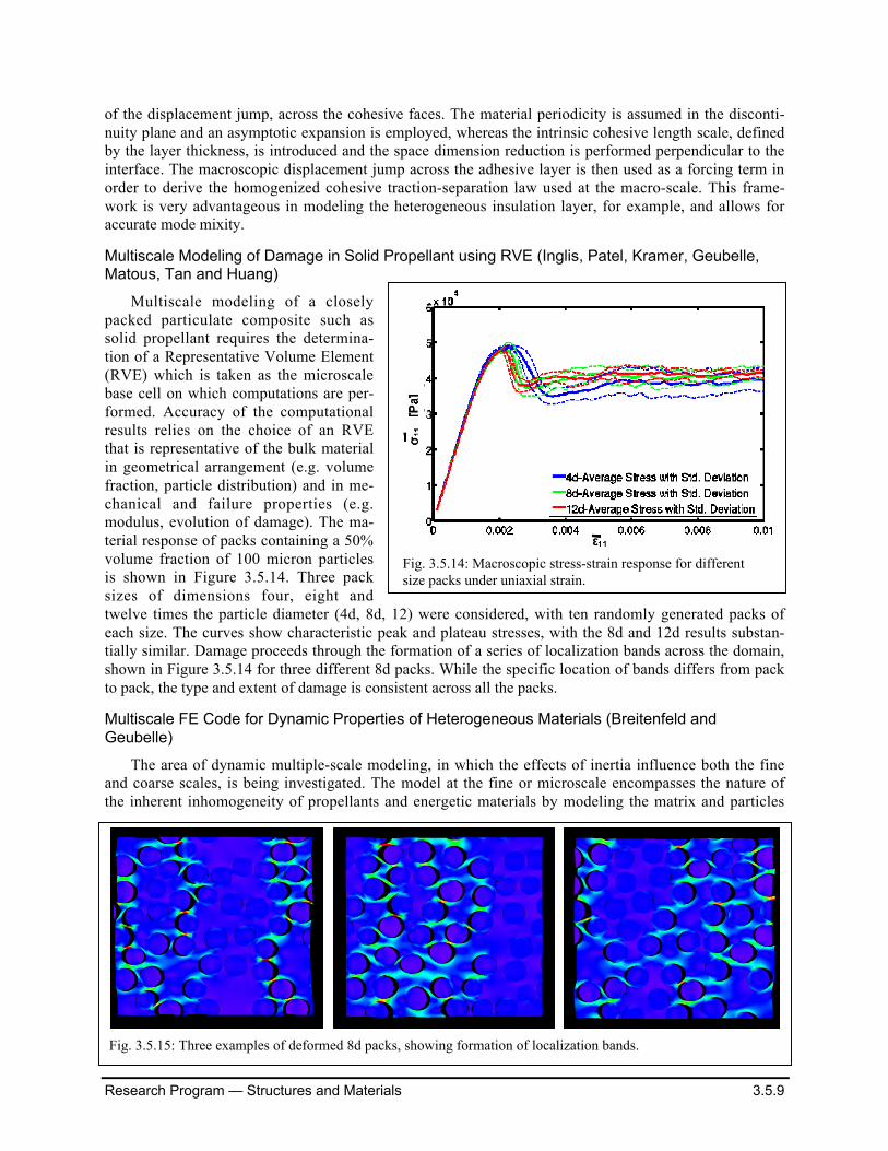
Multiscale Modeling of Damage in Solid Propellant using RVE (Inglis, Patel, Kramer, Geubelle,Matous, Tan and Huang)
Multiscale modeling of a closelypacked particulate composite such assolid propellant requires the determina-tion of a Representative Volume Element(RVE) which is taken as the microscalebase cell on which computations are per-formed. Accuracy of the computationalresults relies on the choice of an RVEthat is representative of the bulk materialin geometrical arrangement (e.g. volumefraction, particle distribution) and in me-chanical and failure properties (e.g.modulus, evolution of damage). The ma-terial response of packs containing a 50%volume fraction of 100 micron particlesis shown in Figure 3.5.14. Three packsizes of dimensions four, eight andtwelve times the particle diameter (4d, 8d, 12) were considered, with ten randomly generated packs ofeach size. The curves show characteristic peak and plateau stresses, with the 8d and 12d results substan-tially similar. Damage proceeds through the formation of a series of localization bands across the domain,shown in Figure 3.5.14 for three different 8d packs. While the specific location of bands differs from packto pack, the type and extent of damage is consistent across all the packs.
Multiscale FE Code for Dynamic Properties of Heterogeneous Materials (Breitenfeld andGeubelle)
The area of dynamic multiple-scale modeling, in which the effects of inertia influence both the fineand coarse scales, is being investigated. The model at the fine or microscale encompasses the nature ofthe inherent inhomogeneity of propellants and energetic materials by modeling the matrix and particles
Fig. 3.5.15: Three examples of deformed 8d packs, showing formation of localization bands.
Fig. 3.5.14: Macroscopic stress-strain response for differentsize packs under uniaxial strain.
Research Program — Structures and Materials 3.5.10
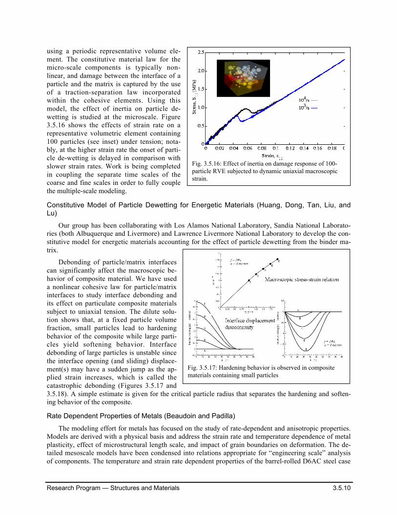
using a periodic representative volume ele-ment. The constitutive material law for themicro-scale components is typically non-linear, and damage between the interface of aparticle and the matrix is captured by the useof a traction-separation law incorporatedwithin the cohesive elements. Using thismodel, the effect of inertia on particle de-wetting is studied at the microscale. Figure3.5.16 shows the effects of strain rate on arepresentative volumetric element containing100 particles (see inset) under tension; nota-bly, at the higher strain rate the onset of parti-cle de-wetting is delayed in comparison withslower strain rates. Work is being completedin coupling the separate time scales of thecoarse and fine scales in order to fully couplethe multiple-scale modeling.
Constitutive Model of Particle Dewetting for Energetic Materials (Huang, Dong, Tan, Liu, andLu)
Our group has been collaborating with Los Alamos National Laboratory, Sandia National Laborato-ries (both Albuquerque and Livermore) and Lawrence Livermore National Laboratory to develop the con-stitutive model for energetic materials accounting for the effect of particle dewetting from the binder ma-trix.
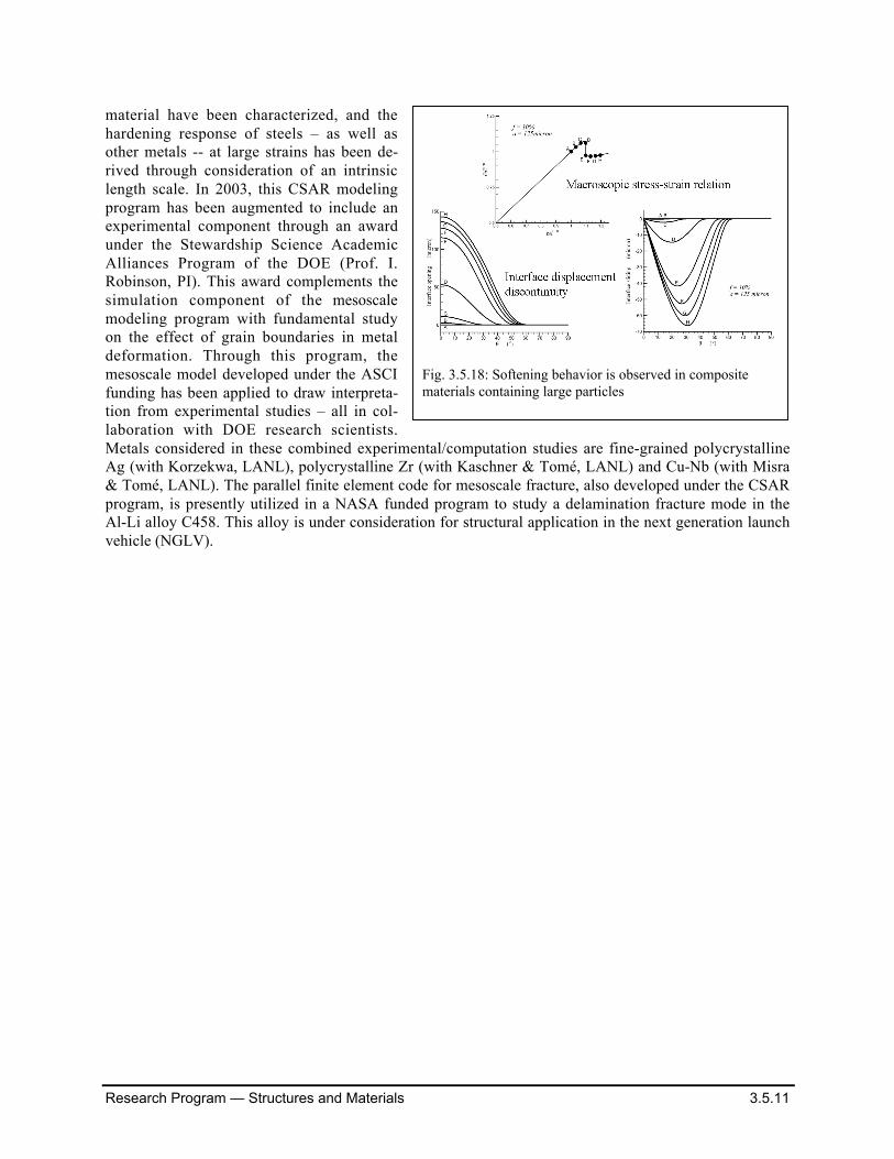
Debonding of particle/matrix interfacescan significantly affect the macroscopic be-havior of composite material. We have useda nonlinear cohesive law for particle/matrixinterfaces to study interface debonding andits effect on particulate composite materialssubject to uniaxial tension. The dilute solu-tion shows that, at a fixed particle volumefraction, small particles lead to hardeningbehavior of the composite while large parti-cles yield softening behavior. Interfacedebonding of large particles is unstable sincethe interface opening (and sliding) displace-ment(s) may have a sudden jump as the ap-plied strain increases, which is called thecatastrophic debonding (Figures 3.5.17 and3.5.18). A simple estimate is given for the critical particle radius that separates the hardening and soften-ing behavior of the composite.
Rate Dependent Properties of Metals (Beaudoin and Padilla)
The modeling effort for metals has focused on the study of rate-dependent and anisotropic properties.Models are derived with a physical basis and address the strain rate and temperature dependence of metalplasticity, effect of microstructural length scale, and impact of grain boundaries on deformation. The de-tailed mesoscale models have been condensed into relations appropriate for “engineering scale” analysisof components. The temperature and strain rate dependent properties of the barrel-rolled D6AC steel case
Fig. 3.5.16: Effect of inertia on damage response of 100-particle RVE subjected to dynamic uniaxial macroscopicstrain.
Fig. 3.5.17: Hardening behavior is observed in compositematerials containing small particles
Research Program — Structures and Materials 3.5.11
material have been characterized, and thehardening response of steels – as well asother metals -- at large strains has been de-rived through consideration of an intrinsiclength scale. In 2003, this CSAR modelingprogram has been augmented to include anexperimental component through an awardunder the Stewardship Science AcademicAlliances Program of the DOE (Prof. I.Robinson, PI). This award complements thesimulation component of the mesoscalemodeling program with fundamental studyon the effect of grain boundaries in metaldeformation. Through this program, themesoscale model developed under the ASCIfunding has been applied to draw interpreta-tion from experimental studies – all in col-laboration with DOE research scientists.Metals considered in these combined experimental/computation studies are fine-grained polycrystallineAg (with Korzekwa, LANL), polycrystalline Zr (with Kaschner & Tomé, LANL) and Cu-Nb (with Misra& Tomé, LANL). The parallel finite element code for mesoscale fracture, also developed under the CSARprogram, is presently utilized in a NASA funded program to study a delamination fracture mode in theAl-Li alloy C458. This alloy is under consideration for structural application in the next generation launchvehicle (NGLV).
Fig. 3.5.18: Softening behavior is observed in compositematerials containing large particles