Embed Size (px)
DESCRIPTION
Stepper Motors when and how to use them
Citation preview

Stepper motors in students' projects - when and howto use them
Les Porter andDaniel Stanton
AbstractDevelopments in simplifying theprogramming of PIC Microcontrollers havemade the devices more accessible to studentsand to school technology departments.Following our paper on interfacing with thePIC, our research I has shown that althoughmany Key Stage 3 and 4 students are nowbeginning to use PICs in their design andmake projects, for many students drivingLEDs to simulate output devices is still as faras they wish to get. Our research also showsthat recently in many schools much progressappears to have been made and DC motorsand other inductive devices are beinginterfaced with the PIC and both Key Stages 3and 4. We have been asked to take the initialpaper a little bit forward and produce someguidelines for driving stepper motors.
This paper provides a short background on thefunctionality of stepper motors and goes on todescribe some possible ways of drivingstepper motors from a PIC.Brunei University
Department ofDesign
IntroductionFollowing our article 'Interfacing Students'Projects with PIC2 Microcontroller' in TheJournal of Design alld Technology Education(Volume 5 No I) we have had a number ofrequests to expand on the article and givesome hints about 'Stepper Motor Driving'.
Figure 1: Unipolarstepper motor.
Stepper motors (in brief)Most school projects that require a motor usea simple DC (direct current) motor. Forexample, to drive a 'buggy' you would usetwo DC motors, one to drive each wheel. Thetwo motors could be controlled independentlyto give the directional movement that thebuggy requires. This could be both runningforward, both running backwards, or onedriving forward while the other is drivingbackwards allowing the vehicle to spin turn.
Unfortunately it is not possible to controlexactly how far each motor turns. Two DCmotors which are manufactured by the samemanufacturer, have the same part number andlook identical will perform in slightly
TEP's stepper Motor EW2017
~
different ways. With a DC motor this problemcould be overcome by electronically countingthe exact number of turns of the shaft andfeeding the information back to themicrocontroller (the PIC), but that is not asstraightforward as it may first seem.
Stepper motors were developed to overcomethis problem. If you have ever thought howyour printer or your photocopy machine candel iver sheet after sheet of paper veryaccurately, then the reason for this is that itsdrive is produced by a stepper motor and not asimple DC motor.
School projects are becoming more and moresophisticated (especially at A' and AS' Level)and we are often getting calls asking for helpin the field of developing projects usingstepper motors, so we thought we would writethis paper to hopefully explain some of theconcepts.
Stepper motors are designed to ease theproblems of accurate rotational movementcontrol. They are available in two types, eitherunipolar or bipolar. In both types the motormoves in a series of steps each turning therotor. Stepper motors are available withdifferent numbers of steps per revolutioncombinations. The most common steppermotor for school use has a 7.50 step anglerotation of the spindle (48 steps perrevolution). The number of steps and speed ofthe motor is determined by the frequency ofthe input single applied.
For the purpose of school projects we wouldsuggest that unipolar stepper motors are easierto work with and in this paper only describetheir use.
Stepper motors are not so easy to drive as arenormal DC motors; they cannot be simply'switched on', but instead must be turned onby sending a series of pulses to the four coilsthat make up the motor.
The motor has four coils (the stator) arrangedaround a permanent magnet rotor. When thesecoils are switched on and off in the correctcombination, the rotor moves in increments orsteps.
The rotor is constructed from a number ofpermanent magnets that obviously have fixedNorth and South poles (see Figure 2).
If two of the opposite stator electromagnetsare turned on, then these draw the rotor to thatpoint. If that pair of electromagnets are thenturned off and the opposite pair are turned onthen the rotor is pulled around by one step.The rotor is then held rigidly at the newposition until the next pair of stator coils isturned on.

To make the diagram clear (Figure 2) onlytwo pairs of coils are shown, not the usualfour pairs.
Driving the stepper motorUntil recently the ubiquitous IC, SA I027, wasmainly used for driving stepper motors inschool projects. This has now become anobsolete IC so we have had to look for othermethods of creating the drive. The PICmicrocontroller has become the obviouschoice for doing this.
The stepper motor can be made to runcontinuously by a four-line program, whichcan be put into an endless software loopwhich will just repeat over and over again at apredetermined speed. See Figures 4a and 4bas an example of this for running bothforward and backward.
For most of your students, that is not whatthey would want to do with a stepper motor.They could produce a 'forward/backward'sequence much more simply and cheaply byusing a DC motor. In our earlier paper wemade a few comments about PICprogramming but in the main discussedinterfacing the microcontroller with students'projects, not the programming. In that paperwe talked about our research programme andwe briefly discussed simplified PICprogramming systems.3 These simplifiedsystems give the PIC user the ability toprogram the microcontroller without having tolearn the intricate commands of theprogramming language, and then when havingwritten the program using an assembler thatthe computer understands and finally'blowing' it to the PIC. If you would like tolearn about programming a PIC from firstprinciples John Morton's new book, PIC-Your Persona/Intraductal)' Course'! willprovide you with all you want to know. Ourresearch shows that for many students all theywant is to get the PIC to control the systemsthat they have designed so the simplifiedprogramming systems prove splendid forthose types of task.
Simplified programmingFor the purpose of driving the stepper motor,we look at two approaches in this paper. Weuse a straightforward program to illustratesuch programming. We look at PIC Logicatorand prCAXE to provide the following projectoutcomes:
press button to start
stepper motor moves forward
some limit switch is sensed
stepper motor drives backwards until...
home position is found.
Figure 2:Stepper motorshowing statorand rotorarrangement.
Coil 1 - RedCoil 2 - BrownCoil 3 - YellowCoil 4 - Blue
In words Digitally
Coil Coil Coil Coil Coil Coil Coil Coil1 2 3 4 1 2 3 4
Step 1 on off off on 1 0 0 1Step 2 on off on off 1 0 1 0Step 3 off on on off 0 1 1 0Steo4 off on off on 0 1 0 1
In words Digitally
Coil Coil Coil Coil Coil Coil Coil Coil1 2 3 4 1 2 3 4
Steo 1 off on on off 0 1 1 0Steo2 on off on off 1 0 1 0Step 3 on off off on 1 0 0 1Step 4 off on off on 0 1 0 1

Figure 5. PICLogicator flowchart for driving astepper motor.
Figure 6a: Forwardmacro.
Figure 6b: Backwardsmacro.
filo fa. ~_ Q-.. a,d !:lot>
1;:I:l~t(@I[ill11 01 1;:;;151 1<c;1l;1~I~t? I-I
~---_. I
motor as running like this themicrocontroller's internal clock would be toofast to drive the motor.
TIIlIIIIlII--
-••II1IIWe have not tried to give examples of digitalswitches as these could be any device, such asa microswitch or photo-diode, that will give adigital signal to the PIC. We have given someadvice on inputs in our earlier paper.
..--,Using PICAXEPICAXE provides a number of ways in whichwe could use the microcontroller. This deviceis based on the 28 pin PIC J 6F872 micro-controller and has its ports predesignated toprovide eight digital outputs, eight digitalinputs, four analogue inputs and two serialinterface pins. It has the ability to be writtento in BASIC (similar to Basic Stampprogramming) or can be programmed viaflowcharts with Crocodile Clips software5
In PIC Logicator (see Figure 5) we use a flowchart with its main tree having six elementswhich include two macros. Each of themacros has six elements.
You will notice that in each of the macros(Figure 6a and Figure 6b) each of the steplines are those that we looked at in Figures 4aand 4b.
This is just the start of the program to givestudents the feel of stepper motor driving.Between each of the step commands in themacros short time delays (wait commands) arerequired to control the speed of steps of the
The power of PICAXE is its simplicity. Noprogrammer, eraser or compl icated electronicsystem. The PIC is programmed via a three-wire connection to the computer's serial port.
itill,ddMU!!¥' xl ii§iitfflCMr!i IMt xl&\(ilI'I your own tltbll't Enter yow own"bet.
@#@ I - ,OUIpurPon: Output Port:
'ib "CflM.,rtttTO' 43 ') 1 .
~7 S 5: 4 ') 2 1 •
~xl I I 1 I I IEnter, t.Jbel or demioo tellt:
~ ~ I ~ ~ ~@!@@ I He'P
Input "ort" , 4321 P
~ilffll·tfffllMifflffli xl '!Mj"tHM,fflfh' xl
I· . \111111111 En(lI'l yoUI own latHtl: El1tttf yOU! U'NfI lil1Jet
~ ~ Help I D!iIJ , - IOlItputPol1: OutplJlPort:
Start switch I iii !I '* J 2 1 . r-;:;- 1 II ~ 4 3 l 1 • ~[ 1 I I 1 I
~ ~~ ~~~
, x 'ts.t:;eMU5t.Mf xlEmr.r you' own litle-I: EnIIN" your own hbel:
I1Ii!!il1Il - t
'ij"'eM.'M' xl Oulputt'or1: OutpulPOf1:7615'1321 0 B 1 G ~ <I J 2 1 0
~Ent8f a '<lbel or decision 1eKt: [11'111'1111 1 ill (III.lJ"'IIlIlI lil:lli\iiIiii\ili I ~ ~~ ~~~
Input Purt:
7 Ii S 4 :) 2 1 D B. 1I.-. II" x x
~ ~ lIelp I [ntsryourown'-bel: fn;er'J/Ol6o""" •• bd
lJiillIlIl lJiillIlIl IOUIputPon: OuIpdPort:
'Until' Limitlli543Zt II B
1 , 5 432 1 • BI I I I I I
~~~ ~~~'fj1uCe.ute xl
&d: ••• htbolll.-tlll!Ckionlell1:- )
InpIJl:Port:., Ii S 4 J 2 1 0 gI ·ItI,JlliIIJ
~~~
'Home' Limrt Switch
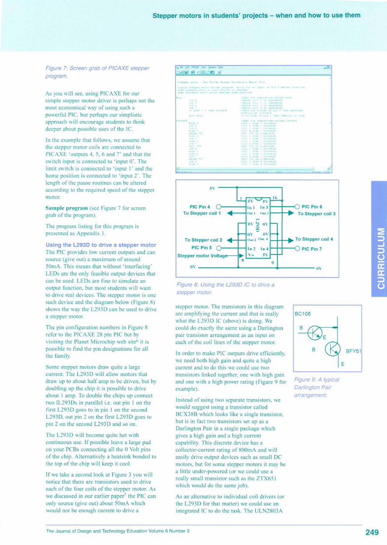
Figure 7: Screen grab of PICAXE stepperprogram.
As you will see, using PICAXE for oursimple stepper motor driver is perhaps not themost economical way of using such apowerful PIC, but perhaps our simplisticapproach will encourage students to thinkdeeper about possible uses of the Ie.
In the example that follows, we assume thatthe stepper motor coils are connected toPICAXE 'outputs 4, 5, 6 and 7' and that theswitch input is connected to 'input 0'. Thelimit switch is connected to 'input I' and thehome position is connected to 'input 2'. Thelength of the pause routines can be alteredaccording to the required speed of the steppermotor.
Sample program (see Figure 7 for screengrab of the program).
The program listing for this program ispresented as Appendix I.
Using the L293D to drive a stepper motorThe PIC provides low current outputs and cansource (give out) a maximum of around50mA. This means that without 'interfacing'LEDs are the only feasible output devices thatcan be used. LEDs are fine to simulate anoutput function, but most students will wantto drive real devices. The stepper motor is onesuch device and the diagram below (Figure 8)shows the way the L293 D can be used to drivea stepper motor.
The pin configuration numbers in Figure 8refer to the PICAXE 28 pin PIC but byvisiting the Planet Microchip web site6 it ispossible to find the pin designations for allthe family.
Some stepper motors draw quite a largecurrent. The L293D will allow motors thatdraw up to about half amp to be driven, but bydoubling up the chip it is possible to driveabout I amp. To double the chips up connecttwo IL293Ds in parallel i.e. out pin I on thefirst L293D goes to in pin I on the secondL293D, out pin 2 on the first L293D goes topin 2 on the second L293D and so on.
The L293D will become quite hot withcontinuous use. If possible leave a large padon your PCBs connecting all the 0 Volt pinsof the chip. Alternatively a heats ink bonded tothe top of the chip will keep it cool.
If we take a second look at Figure 3 you willnotice that there are transistors used to driveeach of the four coils of the stepper motor. Aswe discussed in our earlier paper7 the PIC canonly source (give out) about 50mA whichwould not be enough current to drive a
,_'" t..., .i'~ ~;-~.,~••. tlc. ~IH.,.
PIC Pin 4To Stepper coil 1
PIC Pin 6To Stepper coil 3
To Stepper coil 2
PIC Pin 5
Stepper motor Voltag
In 2 1114Y+ 5V
Figure 8: Using the L293D IC to drive astepper motor.
stepper motor. The transistors in this diagramare amplifying the current and that is reallywhat the L293D IC (above) is doing. Wecould do exactly the same using a Darlingtonpair transistor arrangement as an input oneach of the coil lines of the stepper motor.
In order to make PIC outputs drive efficiently,we need both high gain and quite a highcurrent and to do this we could use twotransistors linked together, one with high gainand one with a high power rating (Figure 9 forexample).
Figure 9: A typicalDarlington Pairarrangement.
Instead of using two separate transistors, wewould suggest using a transistor calledBCX38B which looks like a single transistor,but is in fact two transistors set up as aDarlington Pair in a single package whichgives a high gain and a high currentcapability. This discrete device has acollector-current rating of 800mA and willeasily drive output devices such as small DCmotors, but for some stepper motors it may bea little under-powered (or we could use areally small transistor such as the ZTX65 Iwhich would do the same job).
As an alternative to individual coil drivers (orthe L293D for that matter) we could use anintegrated IC to do the task. The ULN2803A

Figure 10: ULN2803Aused to controlstepper motor (againdiagram or PIC pin-outs refer to PICAXEpin configuration).
Figure 11: 16F84interface board.
Digitalinputs
Figure 12: 16F872interface board.
In1OUII
?In2 Ou(2
::I Cl'In3 Z
0ut.3
4 NIn4 oe Ol\(.,l.
Q5 ~
- In5 > OUIS 14
6in6 OUl6 13
7 In7 00'- 12
8 In8 Om8 11
r:-rnd \ ...10
(Figure 10) is the perfect package for this.This is simply a single chip that contains 8Darlington transistors similar to BCX38B, thechip also contains back EMF suppressiondiodes so therefore no external diodes arerequired. Each Darlington Pair in the IC has acollector-current rating of 550mA whichmakes it a very useful device for drivinginductive components. This really is aversatile IC and has lots of uses, but inFigurelO, above, we give you an example ofhow it could be used to drive a stepper motor.
As part of our research programme we havedeveloped interface boards which could beused for students to interface their PICprograms to stepper motors. Figure I I showsthe interface board that is available for the
Logicator PIC 16F84 driving from L293Dchips and Figure 12 shows the board availableto drive the PICAXE 16F872 chip using theULN2803A Ie.
These boards are available from the Designand Technology Research Bureau at BrunelUniversity7 and can be supplied either asunpopulated circuit boards or part of fullypopulated boards according to the needs ofstudents.
ConclusionsIt is important to remember that steppermotors are designed for specific applicationswhere cheap/accurate positioning andcontrollable speed is required. When studentsare developing projects that require some sortof electromechanical control, think carefullyabout what they really are trying to achieveand see whether they could use a DC motorfirst and measure its relative position usingmicro switches, as this approach tends to becheaper. If they decide that a stepper motor isthe way to go then remember that the wholesystem will require a datum to operate from(the home position) or the stepper motor willlose its way.
Another, sometimes overlooked, considerationis the torque required to operate the system.Cheaper stepper motors have little holdingtorque and will often require adding a gearboxto provide the required driving force. Thisobviously increases the cost of the project andreduces the speed of the motor.
Although the cost may be higher, steppermotors show students a good method ofproviding positional accuracy and with thewidening availability of using microcontrollerbased systems in schools, allows students togain a worthwhile appreciation of rotationalcontrol.

Appendix 1'Simple stepper motor driver program: waits
for an input on Pin 0 before starting.'Goes forward until a limit switch is reached'goes backward until motor reaches homeposition
Main: 'label for subroutine called mainlow 4 'checks coil 1 is unpoweredlow 5 'checks coil 2 is unpoweredlow 6 'checks coil 3 is unpoweredlow 7 'checks coil 4 is unpoweredif pin 0 = 1 then fWd 'looks[or ahigh on pin 0 then pelforms subroutineforward'goto main 'ifno high on pin 0 thenremains in loop
fwd: 'label for subroutine called[fivdlforwardHigh 4 'coil 1 step I forwardslow 5 'coil 2 step 1forwardslow 6 'coil 3 step 1forwardshigh 7 'coil 4 step 1forwardspause 500 'waits 500 millisecondshigh 4 'coil 1 step 2 forwardslow 5 'coil 2 step 2 for .•vardshigh 6 'coil 3 step 2 fa/wardslow 7 'coil 4 step 2 forwardspause 500 'waits 500 millisecondslow 4 'coil 1 step 3[orwardshigh 5 'coil 2 step 3 forwardshigh 6 'coil 3 step 3 forwardslow 7 'coil 4 step 3 forwardspause 500 'waits 500 millisecondslow 4 'coil 1 step 4 forwardshigh 5 'coil 2 step 4[orwardslow 6 'coil 3 step 4 forwardshigh 7 'coil 4 step 4 forwardspause 500 'waits 500 millisecondsifpin 1 = 1 then bkwd 'looks for limitswitch, ifno stays in subroutineforward'goto fivd 'stays in loop forward' unlesslimit switch is found
bkwd: 'label for subroutine called [bkwd]backwardlow 4 'coil 1 step 1 backwardshigh 5 'coil 2 step 1 backwardshigh 6 'coil 3 step 1 backwardslow 7 'coil 4 step 1 backwardspause 500 'waist 500 millisecondshigh 4 'coil 1 step 2 backwardslow 5 'coil 2 step 2 backwardshigh 6 'coil 3 step 2 backwardslow 7 'coil 4 step 2 backwardspause 500 'waits 500 millisecondshigh 4 'coil 1 step 3 backwardslow 5 'coil 2 step 3 backwardslow 6 'coil 3 step 3 backwardshigh 7 'coil 4 step 3 backwardspause 500 'waits 500 millisecondslow 4 'coil I step 4 backwardshigh 5 'coil 2 step 4 bacbvards
low 6 'coil 3 step 4 backwardshigh 7 'coil 4 step 4 bacbvardspause 500 'waits 500 millisecondsi[pin 2 = 1 then main 'looks forhome limit switch, ifno stay insubroutine 'backward'goto bbl'd 'stays in loop 'backward'unless limit switch is found
Notes1 A national research project investigatingteaching and learning within the systems andcontrol strand of the design and technologyNational Curriculum.
2 PIC= Peripheral Interlace Controller. Developedby Microchip Technology inc.: [email protected]
3 TEP's (Technology Enhancement Programme)Chip Shop (Starter Kit £99 + optional software£32)
Economatics - PIC Logicator (£125 includingsoftware)
Icon Soft Electronics - Nottingham TrentUniversity (£98 single user license)
(Since our earlier paper add RevolutionEducation's PICAXE Microcontroller ProgrammingSystem. Business Education Centre, Innova Park,Mollison Avenue, Enfield, Middlesex. EN3 7XUTel: 020 8350 1315.
Kids Chip from Data Harvest (http://www.data-harvest.co.uk/) is also new to the scene and wortha look at. This innovative system offers anexciting, open-ended design opportunity using the'flowol software. In addition to it use as a systemsand control activity, the Kids Chip PIC systemcould be used as part of a textiles, resistantmaterial, graphics or electronics product design.
4 Morton, J. (2000) PIC - Your Personattntroductory Course: Newnes ISBN 0 7506 3932 6
5 Crocodile Clips = Crocodile Clips ltd11Randolph Place Edinburgh Eh3 7TA Tel: +44(0)1312261511 Fax: +44 (0)1312261522Contacts Andrew Hall email:Andrew. [email protected]://www.crocodile-c1ips.com
6 Planet Microchip web site -http://www.microchip.com/10/index.htm - forinformation on all the pin configurations for thePIC family of microcontrollers.
7 The Design and Technology Bureau, BruneiUniversity, Runnymede campus, Egham Surrey.TW200JZ.Http://www.brunel.ac.uk/depts/des/bureau or e-mail [email protected]