Embed Size (px)
Citation preview

3500/46M Hydro Monitor
Mark Snyder
Bently Nevada Senior Field Application Engineer
Older machinery protection systems,
and even transmitters (Reference 1) and
simple vibration switches marketed today,
only produce a “Direct” (broadband)
vibration measurement. Since the Direct
value contains contributions from all
sources of measured vibration, it is the
one measurement that can provide a
comprehensive representation of the overall
health of the machine. However, relying on
this measurement alone has drawbacks.
One problem is that because the Direct
measurement is typically used to alert
operators or trip the machine, Direct alarm
thresholds are set relatively high to suit all
situations and prevent false alarms and
trips. Consequently, these alarms and trips
ignore notable vibration changes in all
but the worst-case operating condition.
Another limitation is that Direct vibration alone merely
provides an indication that there is (or has been) a
problem, but provides little or no useful information to help
you answer the next logical questions of what is causing
the problem, and what operational or maintenance
actions should be taken to mitigate or correct it.
This article describes how an effective
machinery protection/condition monitoring
system solves these problems, and how the
3500/46M Hydro Monitor addresses the unique
needs of hydro turbine generating units.
Phase measurement unlocks predictive maintenance valueToday’s microprocessor-based machinery monitoring
systems can perform signal processing functions that
once required bulky portable analyzers. This enables
the monitor to break out several components and
characteristics of the broadband vibration that can serve
as useful diagnostic “clues.” A good analogy is a musical
chord. An untrained ear can only tell that the overall sound
is dissonant, but cannot tell which of the notes is out of
tune. However, if each note that makes up the chord is
played individually, even an untrained ear can usually
pick out which note is causing the dissonance. Similarly,
exposing individual values that make up the broadband
vibration can help classify the type of machine problem.
Smart Monitoring for the Intelligent Machine Age
ORBIT Vol .4 • No.1 • Jan.214
Hydro CornerDEPARTMENTS

The key to unlocking these individual values is
to incorporate a once-per-turn phase reference
measurement made by a Keyphasor* monitor. Previous
Orbit articles have defined and described the concepts of
phase angle and the Keyphasor measurement (References
2 & 3), and the following is a summary of the functionality
and benefits that a Keyphasor measurement provides.
• A Keyphasor transducer is necessary for
in-place machine balancing; anyone doing
balancing needs the once-per-turn reference
that the Keyphasor channel provides.
• A Keyphasor signal enables the calculation
of “synchronous” data – data that is taken by
synchronizing the vibration waveform sampling
rate with the running speed of the machine.
This preserves the accuracy of phase angle
measurements and the amplitudes of vibration
components that track with machine speed.
• A Keyphasor signal allows the monitoring system
to filter around (isolate) only the vibrations
that have the same frequency as running
speed or multiples of running speed (1X, 2X,
etc.) - even during machine speed changes.
• A Keyphasor measurement provides a phase angle
value associated with the filtered amplitudes of
each transducer measurement. Phase can be
just as useful as amplitude for detecting changes
in the machine behavior. In fact, phase angle
may change even when there is no increase (or
even a decrease) in vibration amplitude.
• Portable analyzers and data acquisition
equipment need a Keyphasor signal to generate
the values and graphical plots necessary to
definitively identify a machinery problem.
The value of filtered amplitude and phase angle values
(e.g., vector values) for machinery monitoring and
predictive maintenance is widely recognized. This
concept is acknowledged in a well- known international
standard on hydroturbine vibration monitoring
(Reference 4). Main points are summarized here:
Three GorGeS DAM In ChInA IS The worlD’S lArGeST hyDroeleCTrIC projeCT
Jan.214 • No.1 • Vol .4 ORBIT 1
Hydro CornerDEPARTMENTS
• Broadband vibration amplitude (without frequency
or phase information) is usually adequate for
operational monitoring and acceptance testing.
• However, vibration vector information is
especially useful for machinery diagnostics
and long-term condition monitoring.
• Some changes in the dynamic state of the
machine cannot be detected and identified
by broad-band measurements alone.
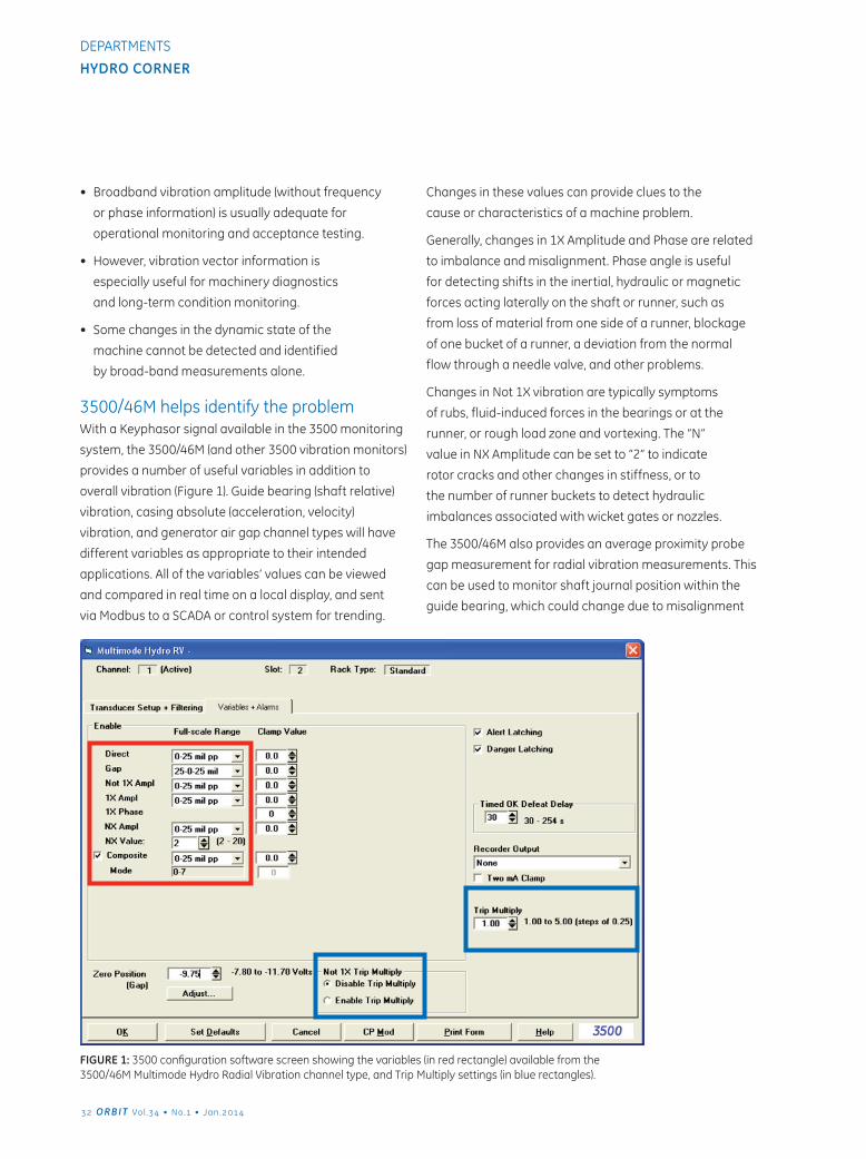
3500/46M helps identify the problemWith a Keyphasor signal available in the 3500 monitoring
system, the 3500/46M (and other 3500 vibration monitors)
provides a number of useful variables in addition to
overall vibration (Figure 1). Guide bearing (shaft relative)
vibration, casing absolute (acceleration, velocity)
vibration, and generator air gap channel types will have
different variables as appropriate to their intended
applications. All of the variables’ values can be viewed
and compared in real time on a local display, and sent
via Modbus to a SCADA or control system for trending.
Changes in these values can provide clues to the
cause or characteristics of a machine problem.
Generally, changes in 1X Amplitude and Phase are related
to imbalance and misalignment. Phase angle is useful
for detecting shifts in the inertial, hydraulic or magnetic
forces acting laterally on the shaft or runner, such as
from loss of material from one side of a runner, blockage
of one bucket of a runner, a deviation from the normal
flow through a needle valve, and other problems.
Changes in Not 1X vibration are typically symptoms
of rubs, fluid-induced forces in the bearings or at the
runner, or rough load zone and vortexing. The “N”
value in NX Amplitude can be set to “2” to indicate
rotor cracks and other changes in stiffness, or to
the number of runner buckets to detect hydraulic
imbalances associated with wicket gates or nozzles.
The 3500/46M also provides an average proximity probe
gap measurement for radial vibration measurements. This
can be used to monitor shaft journal position within the
guide bearing, which could change due to misalignment
FIGure 1: 3500 configuration software screen showing the variables (in red rectangle) available from the 3500/46M Multimode Hydro Radial Vibration channel type, and Trip Multiply settings (in blue rectangles).
2 ORBIT Vol .4 • No.1 • Jan.214
Hydro CornerDEPARTMENTS
and preloads. Gap alarms can be set to indicate when
the normal bearing clearances have been reached or
exceeded (corresponding to potential or actual bearing
wear). Also, this gap measurement, in combination with
the NX measurement set to the number of runner buckets,
is used in the 3500/46M Hydro monitor to calculate a
“Composite” value that can indirectly detect a shear
pin failure in the wicket gate positioning linkage.
Setting Effective Alarm LevelsNow that we have several values to give a more
complete picture of machine condition, the other
challenge is to set alarm levels that are appropriate
for different machine operating conditions. Using
another musical analogy, most compositions contain
both loud and soft segments, and the softer passages
usually cause the audience to quiet down and listen
more carefully to hear the subtle melodies. Similarly,
a good monitoring system should adjust its alarms to
“listen” more or less closely when varying conditions
change the “acceptable” vibration levels for long periods
of normal operation or for short periods during a
start-up sequence and other operational transitions.
One relatively simple way of dealing with the transient
conditions is to use the Trip Multiply feature found in the
3500/46M and other 3500 vibration monitors. Trip Multiply
temporarily elevates alarm levels by a factor set for
each channel in the configuration software (see Figure
1). Note that the Not 1X alarms can be excluded from
the Trip Multiply activity for that channel, which might
be desirable if vibration excursions other than 1X are of
concern during the transitory conditions. The Trip Multiply
condition is actuated for all monitors in a 3500 rack using
a pair of contacts on the 3500/22 TDI Rack Interface
I/O module, or for groups of monitors using a Modbus
digital input via the 3500/92 Communications Gateway.
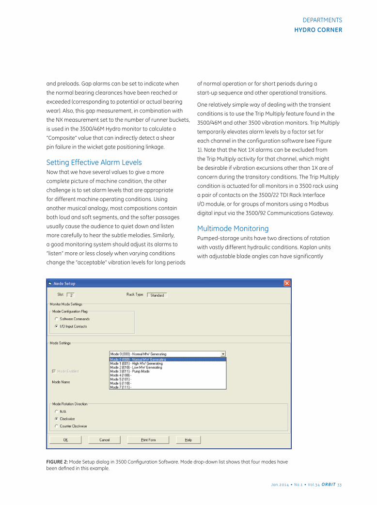
Multimode MonitoringPumped-storage units have two directions of rotation
with vastly different hydraulic conditions. Kaplan units
with adjustable blade angles can have significantly
FIGure 2: Mode Setup dialog in 3500 Configuration Software. Mode drop-down list shows that four modes have been defined in this example.
Jan.214 • No.1 • Vol .4 ORBIT
Hydro CornerDEPARTMENTS
different levels of “normal” vibration, and any hydro
turbine usually has at least one zone of high vibration
associated with certain unavoidable head, speed, and
load conditions. To accommodate these situations, the
3500/46M has a “Multimode” feature that allows you to
establish up to eight (8) distinct machine modes, each with
its own unique set of alarm parameters. The user-defined
modes are enabled and named in the 3500 configuration
software (Figure 2). Typical modes would accommodate
operating conditions such as forward rotation, reverse
rotation, loaded, unloaded, high head, low head, etc.
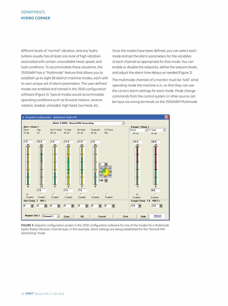
Once the modes have been defined, you can select each
mode and set the alarm parameters for the variables
of each channel as appropriate for that mode. You can
enable or disable the setpoints, define the setpoint levels,
and adjust the alarm time delays as needed (Figure 3).
The multimode channels of a monitor must be “told” what
operating mode the machine is in, so that they can use
the correct alarm settings for each mode. Mode change
commands from the control system or other source can
be input via wiring terminals on the 3500/46M Multimode
FIGure 3: Setpoint configuration screen in the 3500 configuration software for one of the modes for a Multimode Hydro Radial Vibration channel type. In this example, alarm settings are being established for the “Normal MW Generating” mode.
4 ORBIT Vol .4 • No.1 • Jan.214
Hydro CornerDEPARTMENTS
I/O modules, or digitally via a Modbus write command
feature of the 3500/92 Communications Gateway Module.
Toward More “Intelligent” MachinesIn the age of smartphones that incorporate music
players, cameras, portable digital assistants and mobile
GPS devices, it no longer makes sense to use a “dumb”
monitoring system to make intelligent machinery
protection and condition monitoring decisions.
Microprocessor technology has made it possible to
embed powerful signal processing capabilities - once
available only in bulky and cumbersome portable
analyzers - into every channel of an online machinery
monitoring system, while enhancing the effectiveness
of these systems for reliable machinery protection.
This enables the monitor to produce a steady stream
of diagnostic-quality data both locally and remotely,
in real time and for trending in plant historians as part
of a predictive maintenance program. The features
of the 3500/46M Hydro Monitor can extend your
monitoring system from a device that simply tells
you when to shut a machine down, to a powerful
predictive maintenance tool that helps you keep your
hydro turbine generating units humming smoothly.
In a future Hydro Corner article we will describe how
the Multimode feature of the 3500/46M monitor
can work hand-in-hand with the State-Based
Analysis features of System 1* analytic software
to enhance and simplify trending and diagnostics
across the varying operating states of a machine.
References1. Orbit Vol.18 No.1, 1997. Sabin, Steve, “The
limitations of protecting and managing
machinery using vibration ‘transmitters.’”
2. Orbit Vol.20 No.2, 1999. Forland, Clair,
“Why phase information is important for
diagnosing machinery problems.”
3. Orbit Vol.32 No.4, 2012. “Designing and
Machining a Keyphasor Trigger”
4. ISO 10816-5, 2000. International Organization for
Standardization, “Mechanical vibration — Evaluation of
machine vibration by measurements on non-rotating
parts - Part 5: Machine sets in hydraulic power
generating and pumping plants”, Paragraph 5.7.
*Denotes a trademark of Bently Nevada, Inc., a wholly owned subsidiary of General Electric Company.
Copyright © 2013 General Electric Company. All rights reserved.
THE FEATURES OF THE 3500/46M HYDRO MONITOR CAN EXTEND YOUR MONITORING SYSTEM FROM A DEVICE THAT SIMPLY TELLS YOU WHEN TO SHUT A MACHINE DOWN, TO A POWERFUL PREDICTIVE MAINTENANCE TOOL THAT HELPS YOU KEEP YOUR HYDRO TURBINE GENERATING UNITS HUMMING SMOOTHLY.
Jan.214 • No.1 • Vol .4 ORBIT
Hydro CornerDEPARTMENTS

Copyright 2014 Baker Hughes, a GE company, LLC ("BHGE") All rights reserved.
Bently Nevada, Orbit Logo, ADRE, Keyphasor, Promimitor, Velomitor and System 1 are registered trademarks of BHGE in the United States and other countries. All product and company names are
trademarks of their respective holders. Use of the trademarks does not imply any affiliation with or endorsement by the respective holders.
The information contained in this document is subject to change without prior notice.1631 Bently Parkway South, Minden, Nevada USA 89423
Phone: 1.775.782.3611 Bently.com
ORBIT 2014 Q1