Embed Size (px)
Citation preview
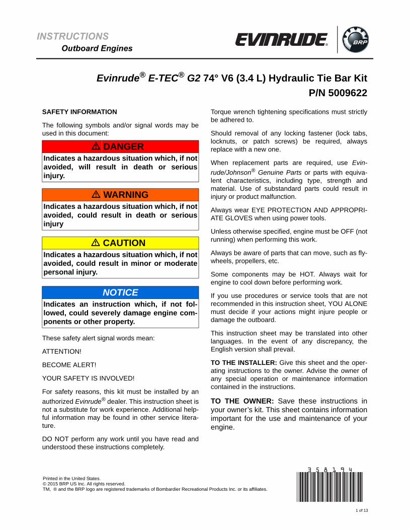
INSTRUCTIONS Outboard Engines
Evinrude® E-TEC® G2 74° V6 (3.4 L) Hydraulic Tie Bar Kit
P/N 5009622
SAFETY INFORMATION
The following symbols and/or signal words may beused in this document:
These safety alert signal words mean:
ATTENTION!
BECOME ALERT!
YOUR SAFETY IS INVOLVED!
For safety reasons, this kit must be installed by an
authorized Evinrude® dealer. This instruction sheet isnot a substitute for work experience. Additional help-ful information may be found in other service litera-ture.
DO NOT perform any work until you have read andunderstood these instructions completely.
Torque wrench tightening specifications must strictlybe adhered to.
Should removal of any locking fastener (lock tabs,locknuts, or patch screws) be required, alwaysreplace with a new one.
When replacement parts are required, use Evin-
rude/Johnson® Genuine Parts or parts with equiva-lent characteristics, including type, strength andmaterial. Use of substandard parts could result ininjury or product malfunction.
Always wear EYE PROTECTION AND APPROPRI-ATE GLOVES when using power tools.
Unless otherwise specified, engine must be OFF (notrunning) when performing this work.
Always be aware of parts that can move, such as fly-wheels, propellers, etc.
Some components may be HOT. Always wait forengine to cool down before performing work.
If you use procedures or service tools that are notrecommended in this instruction sheet, YOU ALONEmust decide if your actions might injure people ordamage the outboard.
This instruction sheet may be translated into otherlanguages. In the event of any discrepancy, theEnglish version shall prevail.
TO THE INSTALLER: Give this sheet and the oper-ating instructions to the owner. Advise the owner ofany special operation or maintenance informationcontained in the instructions.
TO THE OWNER: Save these instructions inyour owner’s kit. This sheet contains informationimportant for the use and maintenance of yourengine.
� DANGERIndicates a hazardous situation which, if notavoided, will result in death or seriousinjury.
� WARNINGIndicates a hazardous situation which, if notavoided, could result in death or seriousinjury
� CAUTIONIndicates a hazardous situation which, if notavoided, could result in minor or moderatepersonal injury.
NOTICEIndicates an instruction which, if not fol-lowed, could severely damage engine com-ponents or other property.
1 of 13
*358194*Printed in the United States.© 2015 BRP US Inc. All rights reserved.TM, ® and the BRP logo are registered trademarks of Bombardier Recreational Products Inc. or its affiliates.
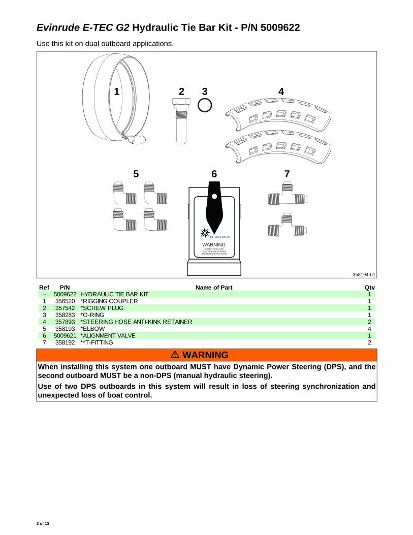
Evinrude E-TEC G2 Hydraulic Tie Bar Kit - P/N 5009622
Use this kit on dual outboard applications.
TIE BAR VALVE
WARNINGDO NOT OPEN WITH
BOAT / ENGINE RUNNING.REFER TO INSTRUCTIONS.
1 2 3
5 6
4
358194-01
7
Ref P/N Name of Part Qty– 5009622 HYDRAULIC TIE BAR KIT 11 356520 *RIGGING COUPLER 12 357542 *SCREW PLUG 13 358283 *O-RING 14 357893 *STEERING HOSE ANTI-KINK RETAINER 25 358193 *ELBOW 46 5009621 *ALIGNMENT VALVE 17 358192 **T-FITTING 2
� WARNINGWhen installing this system one outboard MUST have Dynamic Power Steering (DPS), and thesecond outboard MUST be a non-DPS (manual hydraulic steering).
Use of two DPS outboards in this system will result in loss of steering synchronization andunexpected loss of boat control.
2 of 13
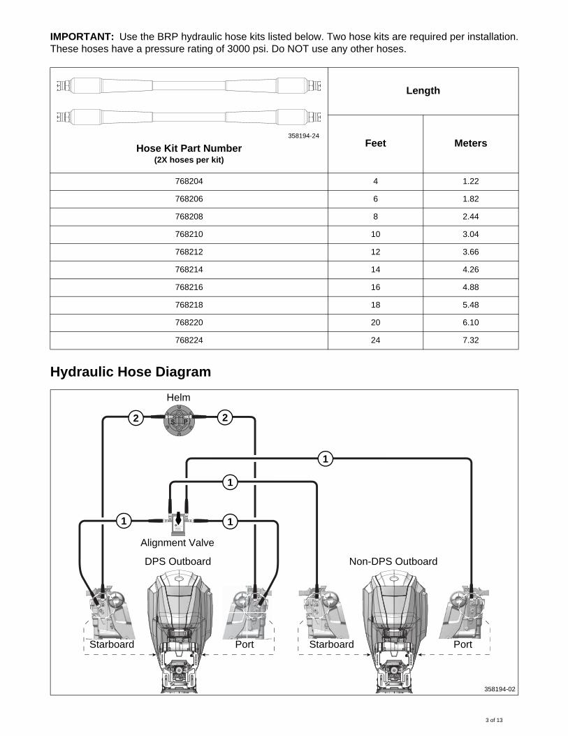
IMPORTANT: Use the BRP hydraulic hose kits listed below. Two hose kits are required per installation.These hoses have a pressure rating of 3000 psi. Do NOT use any other hoses.
Hydraulic Hose Diagram
Hose Kit Part Number(2X hoses per kit)
Length
Feet Meters
768204 4 1.22
768206 6 1.82
768208 8 2.44
768210 10 3.04
768212 12 3.66
768214 14 4.26
768216 16 4.88
768218 18 5.48
768220 20 6.10
768224 24 7.32
358194-24
TIE BAR VALVE
WARNINGDO NOT OPEN WITH
BOAT / ENGINE RUNNING.REFER TO INSTRUCTIONS.
S P
Helm
Starboard Port
DPS Outboard
Port Starboard
Alignment Valve
Non-DPS Outboard
358194-02
1 1
1
1
2 2
3 of 13
Hoses labeled “1” are rated 3000 psi minimum and must be supplied by BRP. Use the table shownabove to select the required hose kit. Hoses labeled “2” can be any hose approved by the helm manu-facturer.
Installation
IMPORTANT: Use of the following kits is required to bleed the hydraulic tie bar system:
• Teleflex Power Purge Jr., P/N 768014• Teleflex Dual Cylinder Bleeding Kit, P/N 768015
See Bleeding the Steering System – Power Purge Method on p. 9
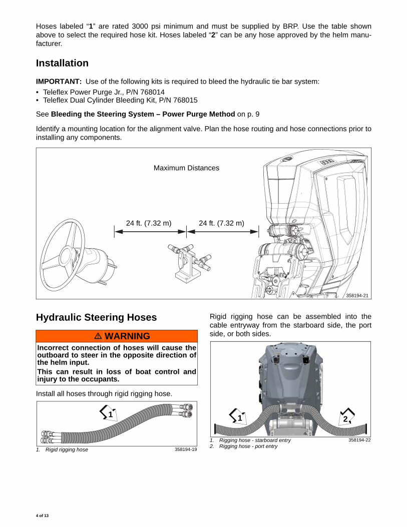
Identify a mounting location for the alignment valve. Plan the hose routing and hose connections prior toinstalling any components.
Hydraulic Steering Hoses
Install all hoses through rigid rigging hose.
Rigid rigging hose can be assembled into thecable entryway from the starboard side, the portside, or both sides.
Maximum Distances
24 ft. (7.32 m) 24 ft. (7.32 m)
358194-21
� WARNINGIncorrect connection of hoses will cause theoutboard to steer in the opposite direction ofthe helm input.This can result in loss of boat control andinjury to the occupants.
1. Rigid rigging hose 358194-19
1
1. Rigging hose - starboard entry2. Rigging hose - port entry
358194-22
1 2
4 of 13
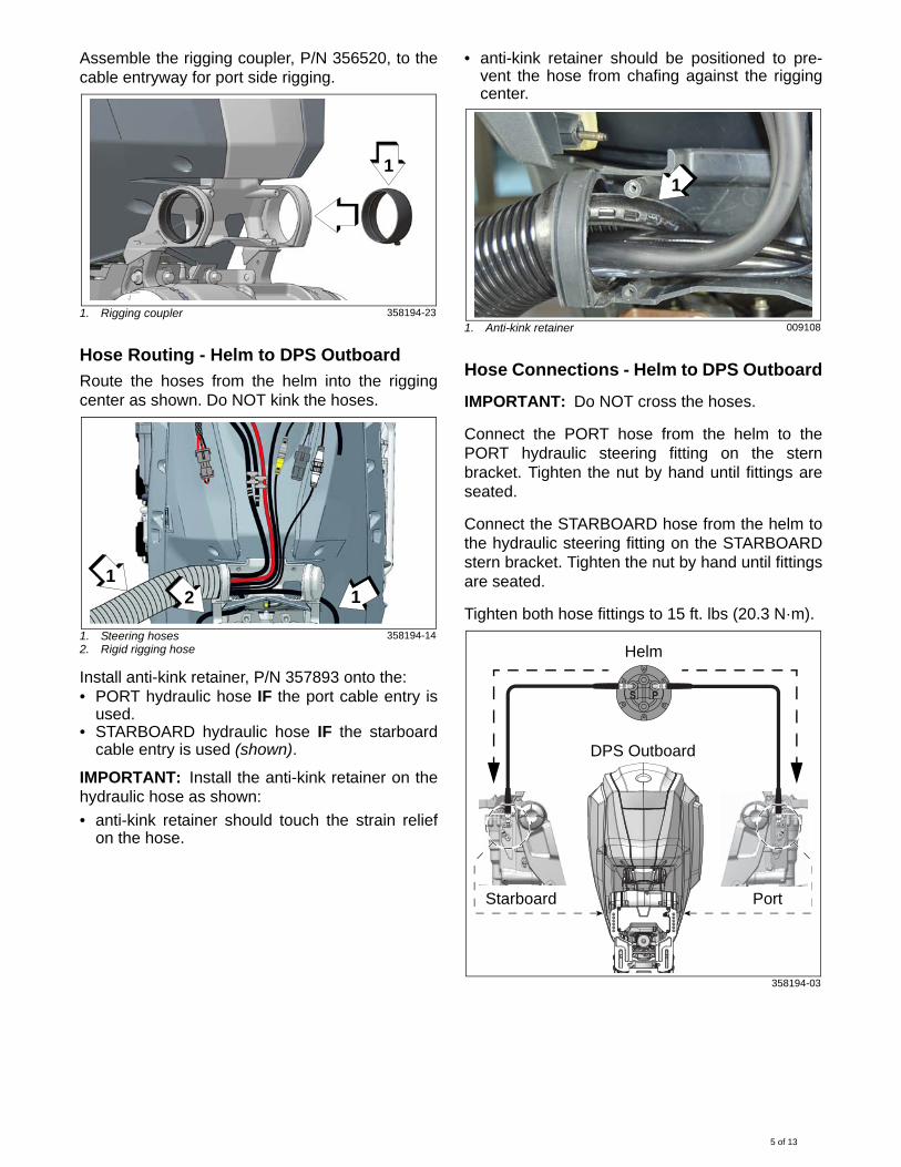
Assemble the rigging coupler, P/N 356520, to thecable entryway for port side rigging.
Hose Routing - Helm to DPS Outboard
Route the hoses from the helm into the riggingcenter as shown. Do NOT kink the hoses.
Install anti-kink retainer, P/N 357893 onto the:• PORT hydraulic hose IF the port cable entry is
used. • STARBOARD hydraulic hose IF the starboard
cable entry is used (shown).
IMPORTANT: Install the anti-kink retainer on thehydraulic hose as shown:
• anti-kink retainer should touch the strain reliefon the hose.
• anti-kink retainer should be positioned to pre-vent the hose from chafing against the riggingcenter.
Hose Connections - Helm to DPS Outboard
IMPORTANT: Do NOT cross the hoses.
Connect the PORT hose from the helm to thePORT hydraulic steering fitting on the sternbracket. Tighten the nut by hand until fittings areseated.
Connect the STARBOARD hose from the helm tothe hydraulic steering fitting on the STARBOARDstern bracket. Tighten the nut by hand until fittingsare seated.
Tighten both hose fittings to 15 ft. lbs (20.3 N·m).
1. Rigging coupler 358194-23
1. Steering hoses2. Rigid rigging hose
358194-14
1
12 1
1. Anti-kink retainer 009108
358194-03
Anti-kink
retainer1
S P
Helm
Starboard Port
DPS Outboard
5 of 13
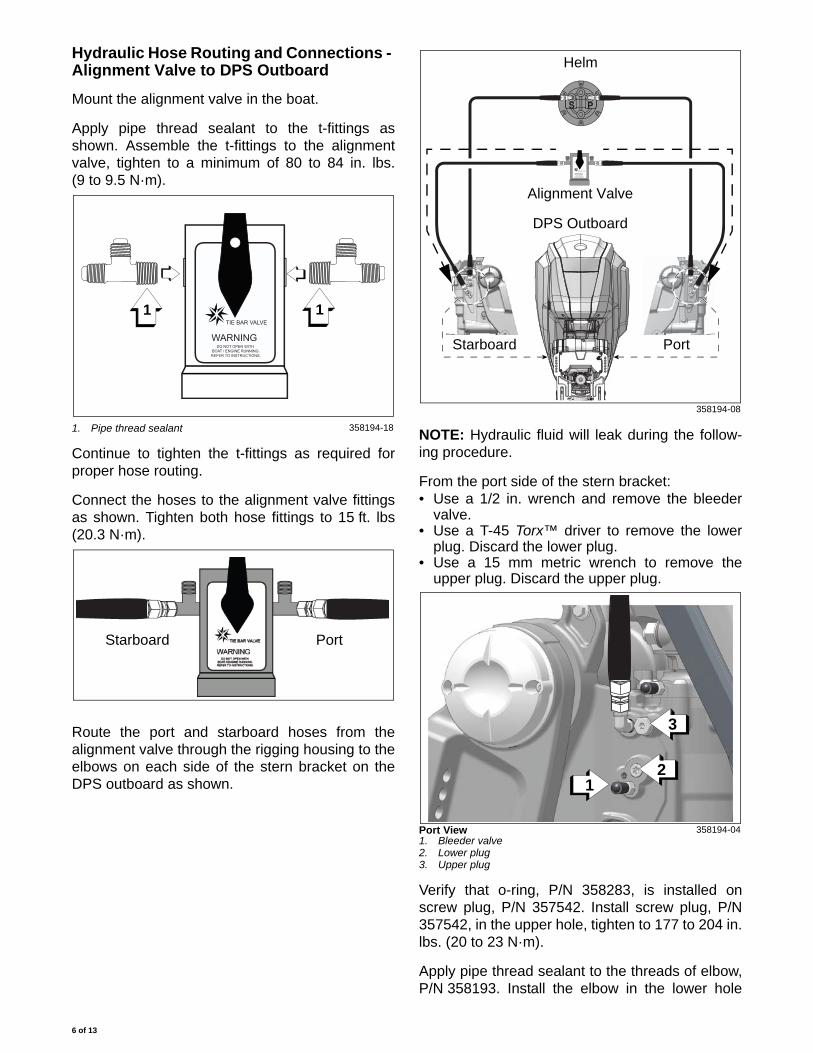
Hydraulic Hose Routing and Connections - Alignment Valve to DPS Outboard
Mount the alignment valve in the boat.
Apply pipe thread sealant to the t-fittings asshown. Assemble the t-fittings to the alignmentvalve, tighten to a minimum of 80 to 84 in. lbs.(9 to 9.5 N·m).
Continue to tighten the t-fittings as required forproper hose routing.
Connect the hoses to the alignment valve fittingsas shown. Tighten both hose fittings to 15 ft. lbs(20.3 N·m).
Route the port and starboard hoses from thealignment valve through the rigging housing to theelbows on each side of the stern bracket on theDPS outboard as shown.
NOTE: Hydraulic fluid will leak during the follow-ing procedure.
From the port side of the stern bracket: • Use a 1/2 in. wrench and remove the bleeder
valve.• Use a T-45 Torx™ driver to remove the lower
plug. Discard the lower plug.• Use a 15 mm metric wrench to remove the
upper plug. Discard the upper plug.
Verify that o-ring, P/N 358283, is installed onscrew plug, P/N 357542. Install screw plug, P/N357542, in the upper hole, tighten to 177 to 204 in.lbs. (20 to 23 N·m).
Apply pipe thread sealant to the threads of elbow,P/N 358193. Install the elbow in the lower hole
1. Pipe thread sealant 358194-18
TIE BAR VALVE
WARNINGDO NOT OPEN WITH
BOAT / ENGINE RUNNING.REFER TO INSTRUCTIONS.
1 1
Starboard Port
358194-08
Port View1. Bleeder valve2. Lower plug3. Upper plug
358194-04
TIE BAR VALVE
WARNINGDO NOT OPEN WITH
BOAT / ENGINE RUNNING.REFER TO INSTRUCTIONS.
S P
Helm
Alignment Valve
Starboard Port
DPS Outboard
3
21
6 of 13
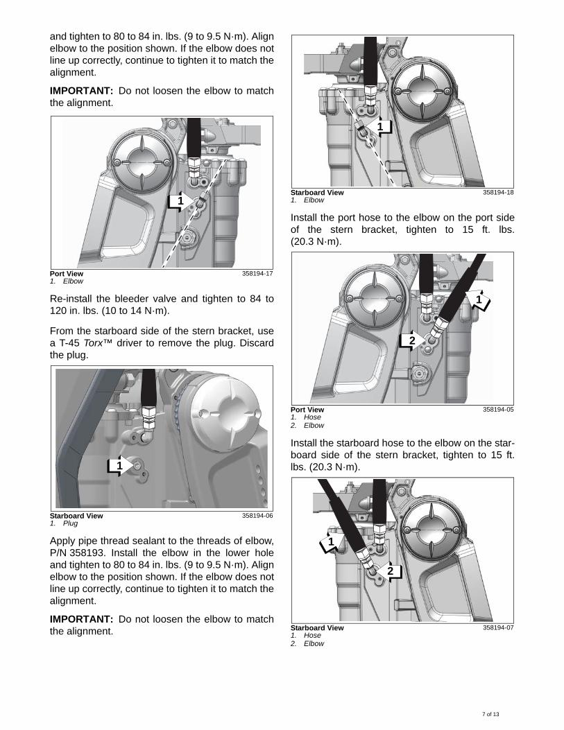
and tighten to 80 to 84 in. lbs. (9 to 9.5 N·m). Alignelbow to the position shown. If the elbow does notline up correctly, continue to tighten it to match thealignment.
IMPORTANT: Do not loosen the elbow to matchthe alignment.
Re-install the bleeder valve and tighten to 84 to120 in. lbs. (10 to 14 N·m).
From the starboard side of the stern bracket, usea T-45 Torx™ driver to remove the plug. Discardthe plug.
Apply pipe thread sealant to the threads of elbow,P/N 358193. Install the elbow in the lower holeand tighten to 80 to 84 in. lbs. (9 to 9.5 N·m). Alignelbow to the position shown. If the elbow does notline up correctly, continue to tighten it to match thealignment.
IMPORTANT: Do not loosen the elbow to matchthe alignment.
Install the port hose to the elbow on the port sideof the stern bracket, tighten to 15 ft. lbs.(20.3 N·m).
Install the starboard hose to the elbow on the star-board side of the stern bracket, tighten to 15 ft.lbs. (20.3 N·m).
Port View1. Elbow
358194-17
Starboard View1. Plug
358194-06
1
1
Starboard View1. Elbow
358194-18
Port View1. Hose2. Elbow
358194-05
Starboard View1. Hose2. Elbow
358194-07
1
2
1
2
1
7 of 13
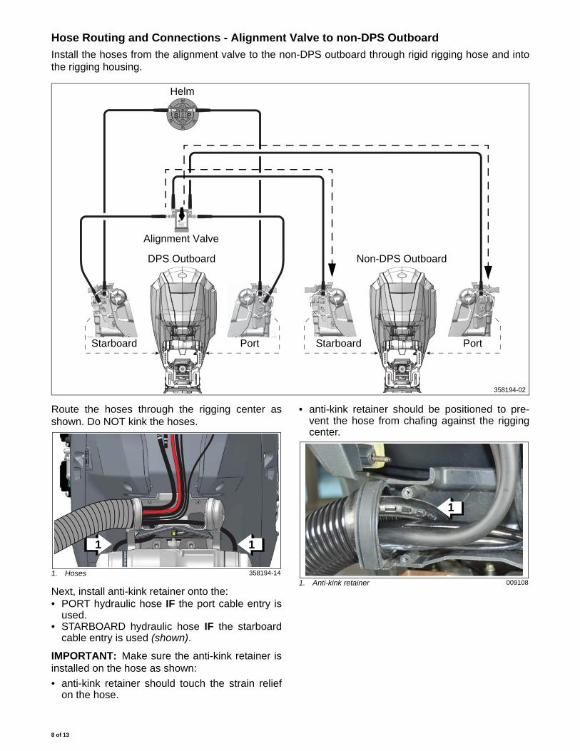
Hose Routing and Connections - Alignment Valve to non-DPS Outboard
Install the hoses from the alignment valve to the non-DPS outboard through rigid rigging hose and intothe rigging housing.
Route the hoses through the rigging center asshown. Do NOT kink the hoses.
Next, install anti-kink retainer onto the:• PORT hydraulic hose IF the port cable entry is
used. • STARBOARD hydraulic hose IF the starboard
cable entry is used (shown).
IMPORTANT: Make sure the anti-kink retainer isinstalled on the hose as shown:
• anti-kink retainer should touch the strain reliefon the hose.
• anti-kink retainer should be positioned to pre-vent the hose from chafing against the riggingcenter.
TIE BAR VALVE
WARNINGDO NOT OPEN WITH
BOAT / ENGINE RUNNING.REFER TO INSTRUCTIONS.
S P
Helm
Starboard Port
DPS Outboard
Port Starboard
Alignment Valve
Non-DPS Outboard
358194-02
1. Hoses 358194-14
11
1. Anti-kink retainer 009108
Anti-kink
retainer
1
8 of 13
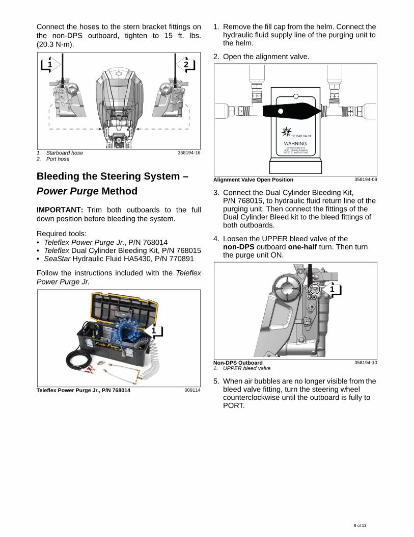
Connect the hoses to the stern bracket fittings onthe non-DPS outboard, tighten to 15 ft. lbs.(20.3 N·m).
Bleeding the Steering System –
Power Purge Method
IMPORTANT: Trim both outboards to the fulldown position before bleeding the system.
Required tools:• Teleflex Power Purge Jr., P/N 768014• Teleflex Dual Cylinder Bleeding Kit, P/N 768015• SeaStar Hydraulic Fluid HA5430, P/N 770891
Follow the instructions included with the TeleflexPower Purge Jr.
1. Remove the fill cap from the helm. Connect the hydraulic fluid supply line of the purging unit to the helm.
2. Open the alignment valve.
3. Connect the Dual Cylinder Bleeding Kit, P/N 768015, to hydraulic fluid return line of the purging unit. Then connect the fittings of the Dual Cylinder Bleed kit to the bleed fittings of both outboards.
4. Loosen the UPPER bleed valve of the non-DPS outboard one-half turn. Then turn the purge unit ON.
5. When air bubbles are no longer visible from the bleed valve fitting, turn the steering wheel counterclockwise until the outboard is fully to PORT.
1. Starboard hose2. Port hose
358194-16
Teleflex Power Purge Jr., P/N 768014 009114
21
1
Alignment Valve Open Position 358194-09
Non-DPS Outboard1. UPPER bleed valve
358194-10
TIE BAR VALVE
WARNINGDO NOT OPEN WITH
BOAT / ENGINE RUNNING.REFER TO INSTRUCTIONS.
1
9 of 13
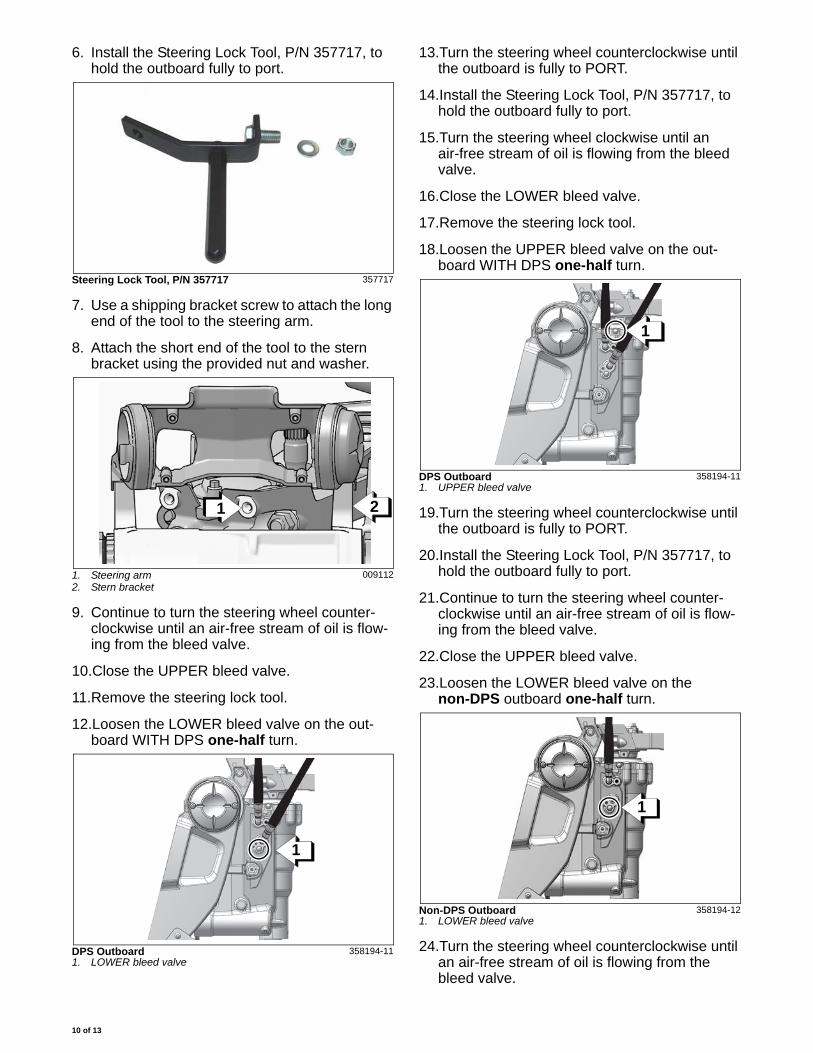
6. Install the Steering Lock Tool, P/N 357717, to hold the outboard fully to port.
7. Use a shipping bracket screw to attach the long end of the tool to the steering arm.
8. Attach the short end of the tool to the stern bracket using the provided nut and washer.
9. Continue to turn the steering wheel counter-clockwise until an air-free stream of oil is flow-ing from the bleed valve.
10.Close the UPPER bleed valve.
11.Remove the steering lock tool.
12.Loosen the LOWER bleed valve on the out-board WITH DPS one-half turn.
13.Turn the steering wheel counterclockwise until the outboard is fully to PORT.
14.Install the Steering Lock Tool, P/N 357717, to hold the outboard fully to port.
15.Turn the steering wheel clockwise until an air-free stream of oil is flowing from the bleed valve.
16.Close the LOWER bleed valve.
17.Remove the steering lock tool.
18.Loosen the UPPER bleed valve on the out-board WITH DPS one-half turn.
19.Turn the steering wheel counterclockwise until the outboard is fully to PORT.
20.Install the Steering Lock Tool, P/N 357717, to hold the outboard fully to port.
21.Continue to turn the steering wheel counter-clockwise until an air-free stream of oil is flow-ing from the bleed valve.
22.Close the UPPER bleed valve.
23.Loosen the LOWER bleed valve on the non-DPS outboard one-half turn.
24.Turn the steering wheel counterclockwise until an air-free stream of oil is flowing from the bleed valve.
Steering Lock Tool, P/N 357717 357717
1. Steering arm2. Stern bracket
009112
DPS Outboard1. LOWER bleed valve
358194-11
1 2
1
DPS Outboard1. UPPER bleed valve
358194-11
Non-DPS Outboard1. LOWER bleed valve
358194-12
1
1
10 of 13
25.Close the LOWER bleed valve.
26.Turn OFF the Power Purge unit.
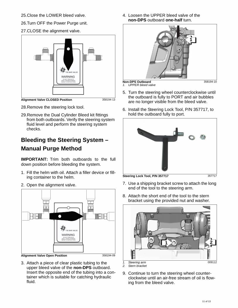
27.CLOSE the alignment valve.
28.Remove the steering lock tool.
29.Remove the Dual Cylinder Bleed kit fittings from both outboards. Verify the steering system fluid level and perform the steering system checks.
Bleeding the Steering System –
Manual Purge Method
IMPORTANT: Trim both outboards to the fulldown position before bleeding the system.
1. Fill the helm with oil. Attach a filler device or fill-ing container to the helm.
2. Open the alignment valve.
3. Attach a piece of clear plastic tubing to the upper bleed valve of the non-DPS outboard. Insert the opposite end of the tubing into a con-tainer which is suitable for catching hydraulic fluid.
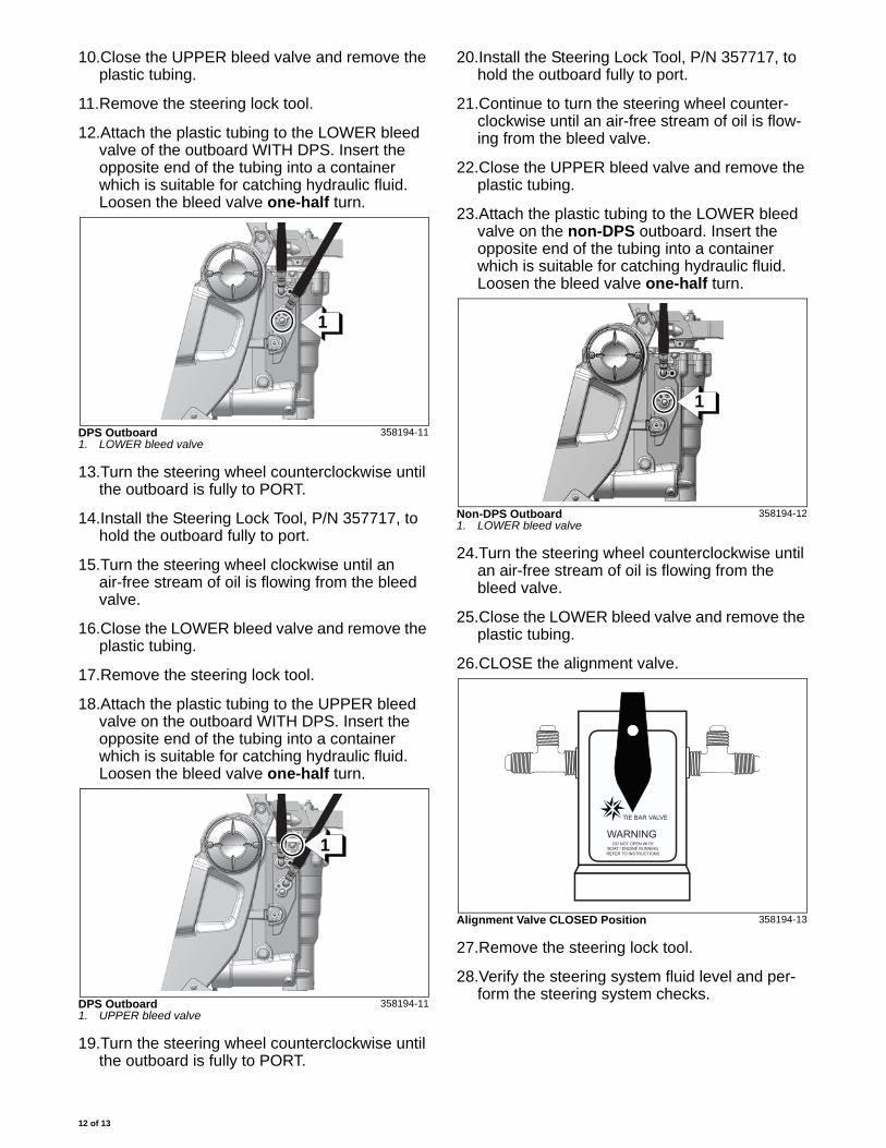
4. Loosen the UPPER bleed valve of the non-DPS outboard one-half turn.
5. Turn the steering wheel counterclockwise until the outboard is fully to PORT and air bubbles are no longer visible from the bleed valve.
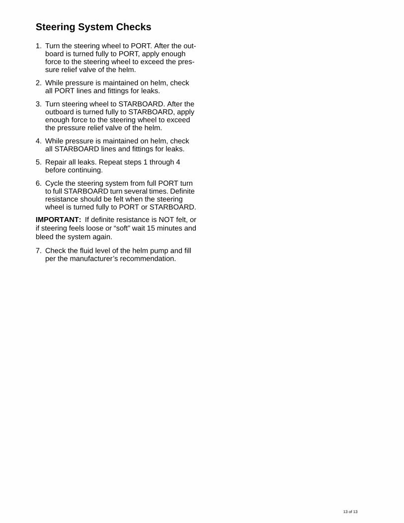
6. Install the Steering Lock Tool, P/N 357717, to hold the outboard fully to port.
7. Use a shipping bracket screw to attach the long end of the tool to the steering arm.
8. Attach the short end of the tool to the stern bracket using the provided nut and washer.
9. Continue to turn the steering wheel counter-clockwise until an air-free stream of oil is flow-ing from the bleed valve.
Alignment Valve CLOSED Position 358194-13
Alignment Valve Open Position 358194-09
TIE BAR VALVE
WARNINGDO NOT OPEN WITH
BOAT / ENGINE RUNNING.REFER TO INSTRUCTIONS.
TIE BAR VALVE
WARNINGDO NOT OPEN WITH
BOAT / ENGINE RUNNING.REFER TO INSTRUCTIONS.
Non-DPS Outboard1. UPPER bleed valve
358194-10
Steering Lock Tool, P/N 357717 357717
1. Steering arm2. Stern bracket
009112
1
1 2
11 of 13
10.Close the UPPER bleed valve and remove the plastic tubing.
11.Remove the steering lock tool.
12.Attach the plastic tubing to the LOWER bleed valve of the outboard WITH DPS. Insert the opposite end of the tubing into a container which is suitable for catching hydraulic fluid. Loosen the bleed valve one-half turn.
13.Turn the steering wheel counterclockwise until the outboard is fully to PORT.
14.Install the Steering Lock Tool, P/N 357717, to hold the outboard fully to port.
15.Turn the steering wheel clockwise until an air-free stream of oil is flowing from the bleed valve.
16.Close the LOWER bleed valve and remove the plastic tubing.
17.Remove the steering lock tool.
18.Attach the plastic tubing to the UPPER bleed valve on the outboard WITH DPS. Insert the opposite end of the tubing into a container which is suitable for catching hydraulic fluid. Loosen the bleed valve one-half turn.
19.Turn the steering wheel counterclockwise until the outboard is fully to PORT.
20.Install the Steering Lock Tool, P/N 357717, to hold the outboard fully to port.
21.Continue to turn the steering wheel counter-clockwise until an air-free stream of oil is flow-ing from the bleed valve.
22.Close the UPPER bleed valve and remove the plastic tubing.
23.Attach the plastic tubing to the LOWER bleed valve on the non-DPS outboard. Insert the opposite end of the tubing into a container which is suitable for catching hydraulic fluid. Loosen the bleed valve one-half turn.
24.Turn the steering wheel counterclockwise until an air-free stream of oil is flowing from the bleed valve.
25.Close the LOWER bleed valve and remove the plastic tubing.
26.CLOSE the alignment valve.
27.Remove the steering lock tool.
28.Verify the steering system fluid level and per-form the steering system checks.
DPS Outboard1. LOWER bleed valve
358194-11
DPS Outboard1. UPPER bleed valve
358194-11
1
1
Non-DPS Outboard1. LOWER bleed valve
358194-12
Alignment Valve CLOSED Position 358194-13
1
TIE BAR VALVE
WARNINGDO NOT OPEN WITH
BOAT / ENGINE RUNNING.REFER TO INSTRUCTIONS.
12 of 13
Steering System Checks
1. Turn the steering wheel to PORT. After the out-board is turned fully to PORT, apply enough force to the steering wheel to exceed the pres-sure relief valve of the helm.
2. While pressure is maintained on helm, check all PORT lines and fittings for leaks.
3. Turn steering wheel to STARBOARD. After the outboard is turned fully to STARBOARD, apply enough force to the steering wheel to exceed the pressure relief valve of the helm.
4. While pressure is maintained on helm, check all STARBOARD lines and fittings for leaks.
5. Repair all leaks. Repeat steps 1 through 4 before continuing.
6. Cycle the steering system from full PORT turn to full STARBOARD turn several times. Definite resistance should be felt when the steering wheel is turned fully to PORT or STARBOARD.
IMPORTANT: If definite resistance is NOT felt, orif steering feels loose or “soft” wait 15 minutes andbleed the system again.
7. Check the fluid level of the helm pump and fill per the manufacturer’s recommendation.
13 of 13