Embed Size (px)
Citation preview
When downloaded from the Generation database, this document is uncontrolled and the responsibility rests with the user to ensure it is in line with the authorised version on the database
Standard
Unique Identifier: 36-943
Old Number: GGS1529
Document Type: GST
Revision: 0
Effective date: April 2008
Title: Engineering Drawing Office and Engineering Documentation Standard
Total pages: 39 Revision date: March 2010 Classification: Controlled
Disclosure
COMPILED BY FUNCTIONAL RESP. AUTHORISED BY HF Swanepoel Leader of development team.
P Khumalo Functional responsible manager
T Moss Authorising manager
Copyright © 2007 Generation Division, Eskom Holdings Limited
Unique Identifier: 36-943 Engineering Drawing Office and Engineering Documentation Standard Revision: 0 Classification: Controlled Disclosure Page: 2 of 39
When downloaded from the Generation database, this document is uncontrolled and the responsibility rests with the user to ensure it is in line with the authorised version on the database
CONTENTS PAGE INTRODUCTION 4 SECTION A - GENERAL DRAWING STANDARD 1. Scope 3 2. Purpose 3 3. Applicability 3 4. Supersede Standards 3 5. Reference Standards 3 6. Codification 4 7. Abbreviations 5 8. Definitions 6 9. CAD Software Requirements 7 10. Documentation 7 11. Classification of Drawings 8 12. Drawing Work Flow 9 13. Requesting of Drawings 9 14. Issuing of Drawings by Eskom 9 15. Issuing of New Drawing Numbers 9 16. Updating and Creating of Drawings 9 17. Drawing Checking Procedure 10 18. Non-Conformance Reporting (NCR) 12 19. Issuing of Drawings to Eskom 12 20. Electronic Format of Drawings Issued to Eskom 12 21. Paper Format of Drawings Issued to Eskom 12 22. Registration of Drawings 13 23. Revision Control 14 24. Contractor Information Back-Up 15 SECTION B - CUSTOMISED CAD FILES 1. Installation of Customised CAD Files for All Drawings 16 2. Installation of Customised CAD Files for P&ID’s AND PFD’s 16 3. Installation of Customised CAD FIles and Cell Libraries for Electrical Diagrams/Drawings
and Ladder Diagrams 16 4. Installation of Customised CAD FIles and Cell Libraries for Control and Instrumentation Diagrams/Drawings 16 5. Installation of Customised CAD FIles and Cell Libraries for Hydraulic and Pneumatic
Diagrams/Drawings 16 SECTION C - ASSOCIATED ENGINEERING INFORMATION/ DOCUMENTATION STANDARDS 1. Reliability Centered Maintenance 17 2. HAZOP Studies/Analysis 18 3. Specification for Technical Documents/Information 18 4. Archiving and Records Storage of Drawings and Engineering Information and Documentation 22 5. Drawing Meta-Data Requirements 6. Disaster Recovery and Business Continuity Planning for Drawings and Engineering Information 22 SECTION D - ANNEXURES 24 Revisions Information 37

Unique Identifier: 36-943 Engineering Drawing Office and Engineering Documentation Standard Revision: 0 Classification: Controlled Disclosure Page: 3 of 39
When downloaded from the Generation database, this document is uncontrolled and the responsibility rests with the user to ensure it is in line with the authorised version on the database
INTRODUCTION
This standard provides the rules for the production and control of engineering drawing office and engineering documentation.
SECTION A – GENERAL DRAWING STANDARD 1. SCOPE The document specifies the procedures and standards that must be adhered to while compiling and distributing engineering drawings and associated engineering documentation.
2. PURPOSE The purpose of the document is to define a procedure that must be followed by the internal Eskom drawing office(s) and Contractor’s drawing office staff. The document specifically defines the procedures and standards for an electronic drawing office utilising CAD/3D Draughting Software. 3. APPLICABILITY This document is applicable to both Eskom and Contractors at all Eskom Generation Division Business Units. Should any changes to this standard be required, all associated Work Instructions (36-944, 36-945, 36-946 and 36-947) must be updated as well due to the cross-referencing contained in the Standard and these Work Instructions. 4. SUPERSEDED STANDARDS The following Eskom Generation Standards are superseded by this document.
Document No Revision Title 167A/143 00 Drawing Office Practice GGG 0450 0 Guideline to Acceptance of Contract Drawings GGS 0182 1 Process Flow Diagrams and Piping Instrumentation Diagrams GGS 0315 0 Standard Drawing Practice GGS 0441 0 Drawing Records System GSE/94/Y004 1 Standard Drawing Practice
5. REFERENCE STANDARDS This document is to be read in conjunction with the following standards and standard instructions:
Document No Rev Title 36-944 General Standard Instruction for General Drawing Software
Configuration 36-945 0 Generation Standard Instruction for P&ID Draughting 36-946 0 Generation Standard Instruction for Electrical Draughting 36-947 0 Generation Standard Instruction for Instrumentation Draughting 32-9 Definition of Eskom Documents EPC0001 Eskom Documentation Management Procedure 36-1 1 Standard for Management System Documents, Correspondence
And Records

Unique Identifier: 36-943 Engineering Drawing Office and Engineering Documentation Standard Revision: 0 Classification: Controlled Disclosure Page: 4 of 39
When downloaded from the Generation database, this document is uncontrolled and the responsibility rests with the user to ensure it is in line with the authorised version on the database
Document No Rev Title 36-2 0 Writing And Controlling Management System Documents. LIM 103 11 AKZ Identification System GGS 0445 0 Drawing Number System GGG 1016 KKS Identification System OPS 0014 1 KKS Key Parts GGS 0442 1 Abbreviation Standard for Chemistry related items for power
stations GGS 0443 2 Abbreviation Standard for Labelling of plant at power stations GGS 0445 1 Drawing Number System ISO 128: 1982 - Technical Drawings – General Principles of Presentation ISO 129 Part I: 2004
- Technical Drawings - Dimensioning
ISO 406: 1987 - Technical Drawings – Tolerancing of Linear and Angular Dimensions
ISO 1101: 2004 - Technical Drawings – Geometrical Tolerancing ISO 1660: 1996 - Technical Drawings – Profile Dimensioning ISO 3040: 1990 - Technical Drawings – Cone Dimensioning ISO 3098 Part I: 2000
- Technical Drawings - Lettering
ISO 5455: 1995 - Technical Drawings - Scales ISO 5459: 1981 - Technical Drawings – Datum Systems for Geometric Tolerancing ISO 6410 Parts I – III: 1996
- Technical Drawings – Representation of Threaded Parts
ISO13567 CAD Layering Standards
6. CODIFICATION 6.1 The plant codification must be in accordance with LIM 103 - AKZ Identification System for the
following site:
6.1.1 Duvha Power Station 6.1.2 Kriel Power Station 6.1.3 Lethabo Power Station 6.1.4 Matla Power Station
6.2 The plant codification must be in accordance with GGG 1016 - KKS Identification System and OPS
0014 – KKS Key Parts Identification System for the following sites:
6.2.1 Acacia Power Station 6.2.2 Ankerlig Power Station 6.2.3 Arnot Power Station 6.2.4 Camden Power Station 6.2.5 Drakensberg Pumped Storage Scheme 6.2.6 Gariep Power Station 6.2.7 Gourikwa Power Station 6.2.8 Grootvlei Power Station 6.2.9 Hendrina Power Station 6.2.10 Ingula Power Station 6.2.11 Kendal Power Station 6.2.12 Komati Power Station 6.2.13 Majuba Power Station 6.2.14 Matimba Power Station 6.2.15 Medupi Power Station 6.2.16 Palmiet Pump Storage Scheme 6.2.17 Port Rex Power Station

Unique Identifier: 36-943 Engineering Drawing Office and Engineering Documentation Standard Revision: 0 Classification: Controlled Disclosure Page: 5 of 39
When downloaded from the Generation database, this document is uncontrolled and the responsibility rests with the user to ensure it is in line with the authorised version on the database
6.2.18 Tutuka Power Station 6.2.19 Vanderkloof Power Station
6.3 The required codification standard for Nuclear Plant is obtainable from the Drawing & Design Office
at Koeberg Power Station. The plant codification must be in accordance with nuclear plant requirements for the following sites:
6.3.1 Koeberg Power Station 6.3.2 Pebble Bed Modular Reactor (PBMR) 6.3.3 Future Nuclear Power Stations 6.4 The numbering of drawings shall be done in accordance with GGS 0445 (Generation Drawing
Number System Standard). Only Section 4.1.1, 4.1.3 and Annexures A, C, G, H, L, M and R of GGS 0445 shall apply for use with this drawing standard.
7. ABBREVIATIONS 7.1 BCP - Business Continuity Plan 7.2 CAD - Computer Aided Draughting 7.3 DGN - Bentley MicroStation Drawing File Extension 7.4 DRP - Disaster Recovery Plan 7.5 DWG/DXF - AutoCAD Drawing File Extensions 7.6 EDMS - Electronic Document Management System 7.7 HVAC - Heating Ventilation Air Conditioning 7.8 IBI - Integrated Business Improvement Philosophy/Methodology 7.9 MWP - Megawatt Park 7.10 MTBF - Mean Time Between Failures 7.11 MTTR - Mean Time To Repair 7.12 NCR - Non Conformance Report 7.13 NDT - Non-Destructive Testing 7.14 OEM - Original Equipment Manufacturer 7.15 OHSAct - Occupational Health and Safety Act of 1993 7.16 PDF - Portable Document Format 7.17 PDB - Project Data Base 7.18 P&ID - Process & Instrumentation Diagram/Piping & Instrumentation Diagram 7.19 PFD - Process Flow Diagram 7.20 PPE - Personnel Protective Equipment 7.21 Pr Eng - Professional Engineer registered in terms of the Engineering Profession Act, 2000
Unique Identifier: 36-943 Engineering Drawing Office and Engineering Documentation Standard Revision: 0 Classification: Controlled Disclosure Page: 6 of 39
When downloaded from the Generation database, this document is uncontrolled and the responsibility rests with the user to ensure it is in line with the authorised version on the database
7.22 RCM - Reliability Centred Maintenance 7.23 RFT - Request for Tender 7.24 SoW - Scope of Work 7.25 TIFF - Tagged Image File Format
8. DEFINITIONS 8.1 As Built Drawing: Drawing which is verified as an exact representation of a plant or a section of a
plant that has been completely built. 8.2 As Designed Drawing: A drawing which would be published as per the final design for
implementation and construction. 8.3 Check Print: Drawing which is printed and utilised for verification of a drawing during the drawing
checking procedure. 8.4 Contractor: A party appointed by Eskom to render services. 8.5 Data Mining: For the purposes of this standard Data Mining shall be the extraction of Text Tagged
data from CAD drawings. 8.6 Controlled Copy: A copy of a document held by a documentation/satellite centre or by a designated
individual that has the guarantee that it is the latest and current valid revision. This copy shall be clearly stamped in red “CONTROLLED COPY”. All controlled documents that are printed will be considered valid for a maximum period of 24 hours. Users shall always reference back to the EDMS for the latest version of a document.
8.7 Deviation Process: This process is the initiator of engineering activities to permanently address plant
deficiencies or incidents. 8.8 Draughtsperson: A person responsible for the creation and updating of drawings, in accordance with
this standard. 8.9 Functional Process Flow Diagram (FPFD): Diagram showing all or a recognisable portion of the
process, complete with a material and/or heat balance sheet. It contains details of operating parameters such as flow rate, temperature and pressure.
8.10 Piping and Instrumentation Diagram (P&ID): Diagram which shows limited details of the
mechanical and electrical components, pipework and ducting, and identifies all the measuring points and control elements that are necessary to measure and control that process.
8.11 Plant System: A collection of plant components connected in such a way that each will perform a
unique process, thereby achieving specified performance parameters. 8.12 Preliminary: When a drawing is authorised but has not been implemented or has not reached ‘As-
Built’ status. 8.13 Primary Process Flow Diagram (PPFD): Diagram which indicates the major process as well as the
process values through all or most of the main plant items of a given power station or system. 8.14 Project Configuration Files: The customised setup files that must be utilised in conjunction with
Bentley PlantSpace P&ID. 8.15 Secondary Process Flow Diagram (SPFD): Secondary process flow diagram is similar to the
primary process flow diagram (PPFD), except that it only deals with one particular system or subsystem of plant, and in more detail.
Unique Identifier: 36-943 Engineering Drawing Office and Engineering Documentation Standard Revision: 0 Classification: Controlled Disclosure Page: 7 of 39
When downloaded from the Generation database, this document is uncontrolled and the responsibility rests with the user to ensure it is in line with the authorised version on the database
8.16 Text Tagging: For the purposes of this standard Text Tagging shall be the process of adding electronic text tags into a CAD drawing for the purpose of data mining.
9. CAD SOFTWARE REQUIREMENTS The minimum CAD software requirements are specified below. Additional add-on Bentley software packages can be utilised.
9.1 Bentley MicroStation Version 08.05.02.27
Shall be used for General Arrangement, Sectional Views and Detail Drawings for the following drawing types/disciplines: • Architectural • Civil • Structural • Mechanical • Piping • Lighting • HVAC • Electrical • Text Tagging of existing drawings for data mining
9.2 Bentley Knowledge Manager Version 08.05.0.10
• Shall be used for the mining of Text Tagged Drawings
9.3 Bentley Data Manager Version 08.06.0.79
• Shall be used for the management of equipment data sheets
9.4 Bentley Vision Version 08.06.0.79
This shall be used as the Universal Viewing Interface for: • PlantSpace P&ID • Knowledge Manager • Data Manager
9.5 Bentley I/RAS B 2004 Edition Version 08.05.02.27
This shall be used as the Viewing and Editing Interface for hybrid drawings, eg drawings consisting of a.tif layer and a .dgn layer.
10. DOCUMENTATION The requirements for specific drawing documents are specified below. 10.1 General Drawings
10.1.1 Draughting of all Drawings, including Text-Tagged Drawings shall be done in accordance with 36-
944 (Generation General Drawing Standard Work Instruction). “Intelligent” P&ID’s, Electrical and C&I Drawings will be done in accordance with 10.2, 10.3, 10.4 and 10.5 of this Standard.
10.2 Process Flow Diagrams (PPFD, SPFD and FPFD)
10.2.1 Draughting of PPFD, SPFD and FPFD’s shall be done in accordance with 36-945 (Generation
Standard Work Instruction for Process, Hydraulic and Pneumatic Drawings). Configuration of the required CAD Software shall be in accordance with 36-945.

Unique Identifier: 36-943 Engineering Drawing Office and Engineering Documentation Standard Revision: 0 Classification: Controlled Disclosure Page: 8 of 39
When downloaded from the Generation database, this document is uncontrolled and the responsibility rests with the user to ensure it is in line with the authorised version on the database
10.2.2 Draughting shall be done using the Standard Eskom Cell Library for Process Diagrams, contained
as Annexure “A” in 36-945. 10.3 Piping and Instrumentation Diagrams (P&ID)
10.3.1 Draughting of P&ID’s shall be done in accordance with 36-945 (Generation Standard Work
Instruction for Process, Hydraulic and Pneumatic Drawings). Configuration of the required CAD Software shall be in accordance with 36-945.
10.3.2 Draughting of P&ID’s shall be done using the Standard Eskom Cell Library for Process Diagrams,
contained as Annexure “A” in 36-945. 10.3.3 Draughting of Hydraulic and Pneumatic Circuits shall be done using the Standard Eskom Cell
Library for Hydraulic and Pneumatic Diagrams, contained as Annexure “B” in 36-945. 10.4 Electrical Diagrams (I&W) Drawings 10.4.1 Draughting of Electrical Diagrams shall be done in accordance with 36-946 (Electrical Drawing and
Documentation Standard Work Instruction). Configuration of the required CAD Software shall be in accordance with 36-946.
10.4.2 Draughting will be done using the Standard Eskom Cell Library for Electrical Diagrams, contained
as Annexure “C” in 36-946. 10.4.3 For “Ladder Diagrams”, Draughting shall be done using the Standard Eskom Cell Library for Ladder
Diagrams, contained as Annexure “D” in 36-946. 10.5 Instrumentation Diagrams 10.5.1 Draughting of Instrumentation Diagrams shall be done in accordance with 36-947 (Instrumentation
Drawing and Documentation Standard Work Instruction). Configuration of the required CAD Software shall be in accordance with 36-947.
10.5.2 Draughting will be done using the Standard Eskom Cell Library for Instrumentation Diagrams,
contained as Appendix “K” in 36-947.
11. CLASSIFICATION OF DRAWINGS 11.1 Drawings shall be classified according to at least the following information classification levels:
• Level 1
Secret: Only for use within specified segments in the organisation
• Level 2 Confidential: May not be disclosed outside of Eskom – represents a competitive advantage for the business.
• Level 3 Controlled Disclosure: Internal Information – controlled disclosure to any external parties – either enforced by law or discretionary
• Level 4 Public Domain/Non-Classified: Published in any public forum without constraints, either enforced by law or discretionary
11.2 This classification shall form part of the document record in the EDMS/Engineering Management
System and user access to the drawing(s) will be restricted accordingly.

Unique Identifier: 36-943 Engineering Drawing Office and Engineering Documentation Standard Revision: 0 Classification: Controlled Disclosure Page: 9 of 39
When downloaded from the Generation database, this document is uncontrolled and the responsibility rests with the user to ensure it is in line with the authorised version on the database
12. DRAWING WORK FLOW 12.1 The issuing, updating and creating of drawings must be in accordance with the Drawing Work Flow
which is included in this document as Annexure “A”. 13. REQUESTING OF DRAWINGS 13.1 Copies of existing drawings must be requested in writing by submitting a completed standard
drawing requisition form to the Eskom Drawing Office Document Controller. 13.2 All requests for drawings shall form part of a request for Technical Information Change (TIC). A
deviation must be registered by the designated Eskom Drawing Office Document Controller or EDMS Administrator prior to drawings being issued to any party.
13.3 Should any drawing be required by a Contractor or third party the Eskom Non-Disclosure Agreement
form must be signed off by the Contractor or third party and sent to the designated Eskom Drawing Office Document Controller prior to the drawing being issued.
13.4 An example of the minimum content for non-disclosure form/agreement is attached as Annexure “I”. 13.5 The standard format for a drawing requisition is attached as Annexure “B”. 14. ISSUING OF DRAWINGS BY ESKOM 14.1 All drawings issued by Eskom must be issued by the designated Eskom Drawing Office Document
Controller via a document transmittal and signed by the applicable authoriser. 14.2 The recipient of the drawings must acknowledge receipt of the drawings by signing the document
transmittal and returning the signed transmittal to the designated Eskom Drawing Office Document Controller.
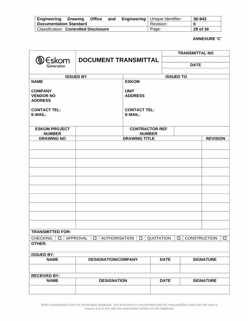
14.3 The recommended format for a document transmittal is attached as Annexure “C”. 15. ISSUING OF NEW DRAWING NUMBERS
15.1 Drawings numbers must be requested in writing by submitting a completed standard drawing
requisition form Annexure “B” to the designated Eskom Drawing Office Document Controller. 15.2 The recommended format for a drawing requisition is attached as Annexure “B”.
16. UPDATING AND CREATING OF DRAWINGS
16.1 General Drawings must be created and updated in accordance with 36-944 (Generation General
Drawings Standard Work Instruction). 16.2 Text Tagged Drawings for data mining must be created and updated in accordance with 36-944
(Generation General Drawings Standard Work Instruction). 16.3 Draughting of PPFD, SPFD, FPFD and P&ID’s shall be done in accordance with 36-945 (Generation
Standard Work Instruction for Process, Hydraulic and Pneumatic Drawings). Configuration of the required CAD Software shall be in accordance with 36-945. Draughting shall be done using the Standard Eskom Cell Library for Process Diagrams, contained as an Annexure “A” in 36-945. Draughting of Hydraulic and Pneumatic Circuits shall be done using the Standard Eskom Cell Library for Hydraulic and Pneumatic Diagrams, contained as an Annexure “B” in 36-945.
Unique Identifier: 36-943 Engineering Drawing Office and Engineering Documentation Standard Revision: 0 Classification: Controlled Disclosure Page: 10 of 39
When downloaded from the Generation database, this document is uncontrolled and the responsibility rests with the user to ensure it is in line with the authorised version on the database
16.4 Draughting of Electrical Diagrams shall be done in accordance with 36-946 (Generation Standard Work Instruction for Electrical Drawings). Configuration of the required CAD Software shall be in accordance with 36-946. Draughting will be done using the Standard Eskom Cell Library for Electrical Diagrams, contained as an Annexure ”A” in 36-946. For “Ladder Diagrams”, Draughting shall be done using the Standard Eskom Cell Library for Ladder Diagrams, contained as an Annexure “B” in 36-946.
16.5 Draughting of Instrumentation Diagrams shall be done in accordance with 36-947 (Generation
Standard Work Instruction for Instrumentation Drawings and Documentation). Configuration of the required CAD Software shall be in accordance with 36-947. Draughting will be done using the Standard Eskom Cell Library for Instrumentation Diagrams, contained as Annexure “K” in 36-947.
16.3 The following best practice shall be applied in the creation of drawings:
• Drawings shall be properly planned and produced to ensure ease of interpretation and read-ability.
• Typical details are not to be duplicated, appropriate references shall be used in the main drawing to indicate repetition of any typical details (Except for P&ID’s – see last point in this list).
• The use of unnecessary views shall be eliminated. • Application of a constant set of scales on sets of drawings. • Avoidance of odd scales, using the most common scales like 1:50, 1:20, 1:10, 1:2, etc • Provision of cross-reference information shall be provided on drawings, ie reference to other
drawings as well as to design information/manuals as appropriate. • Manufacturer’s information and datasheets shall be provided in a MicroSoft MSExcel or
MSAccess format that is year 2000 compliant. The display of this information on drawings shall be minimised as far as possible.
• The use of standard symbols for P&ID’s, PFD’s, Hydraulic, Pneumatic, Electrical and Control & Instrumentation drawings as indicated in this document. These symbols are contained in the relevant Cell Libraries to be used within the Bentley MicroStation and Related Software.
• As P&ID’s will be used to generate the plant configuration data-set for the power station in question, they will be appropriately replicated to cater for the number of installed units, systems, sub-systems and duplicate components at the power station. The use of “Typical Drawings” shall not be allowed, ie one P&ID for Units 1 to 6.
17. DRAWING CHECKING PROCEDURE The following auditable procedure must be followed to check all drawings: 17.1 Once the draughtsperson has completed a drawing a check print must be issued to the responsible
engineer or draughtsperson. The check print must be clearly stamped “CHECK PRINT”. 17.2 The responsible engineer or draughtsperson must check the drawing:
• against the relevant marked up drawing • with the plant configuration/codification officer to ensure that all tagged items comply with the
KKS or AKZ site codification system as required 17.3 The check by the responsible draughtsperson is performed to ensure that the drawing standards are
adhered to and that all the marked-up items have been incorporated as required. 17.4 A standard checklist for drawings that must be used as a basis for checking that the drawing
standards are adhered to is attached as Annexure “H”. 17.5 The check by the responsible engineer is to ensure that the design changes are incorporated as
required.
Unique Identifier: 36-943 Engineering Drawing Office and Engineering Documentation Standard Revision: 0 Classification: Controlled Disclosure Page: 11 of 39
When downloaded from the Generation database, this document is uncontrolled and the responsibility rests with the user to ensure it is in line with the authorised version on the database
17.6 Once the responsible engineer or draughtsperson has completed checking a drawing the check print must be signed and dated and the full name of the checker must be recorded on the drawing.
17.7 The drawings must then be returned to the responsible draughtsperson. All discrepancies or queries must be clearly marked up utilising the following colour code system and reviewed with the responsible draughtsperson.
• Red - Corrections • Yellow - Delete • Blue - Comments (will not be draughted) • Green - Correct
17.8 The draughtsperson must back draught the “CHECK PRINT” drawing and re-issue the drawing to the
responsible engineer or draughtsperson as a revised “CHECK PRINT” for re-checking. Once no more discrepancies are marked up on the “CHECK PRINT” by the responsible engineer or draughtsperson and he/she has signed off the drawing the drawing is ready for issue to Eskom for the required approvals.
17.9 Note all superseded paper copies of all drawings must be clearly stamped “SUPERSEDED” by the
responsible draughtsperson as soon as the corrections have been made. 17.10 All “SUPERSEDED” drawings must be retained as part of the drawing office records. 17.11 If required the drawing must be issued to Eskom for checking in accordance with Clause A.19.0. 17.12 Each drawing issued to Eskom for checking must be issued together with a NCR which specifies all
outstanding issues relating to the drawing that must be resolved by Eskom. NCR’s must be created for all drawings whether or not they have outstanding issues.
17.13 Each drawing issued to Eskom for checking must be clearly stamped “CHECK PRINT”. 17.14 Eskom must appoint a responsible engineer or draughtsperson to check the drawing and resolve all
the items listed on the NCR. 17.15 Once the Eskom responsible engineer or draughtsperson has completed checking a drawing the
check print must be signed and dated and the full name of the checker must be recorded on the drawing.
17.16 The drawing must then be returned to the responsible draughtsperson or Contractor. All
discrepancies or queries must be clearly marked up utilising the following colour code system and reviewed with the responsible draughtsperson.
• Red Corrections • Yellow Delete • Blue Comments (will not be draughted) • Green Correct
17.17 If required the drawing must be issued to the Contractor for updating/back-draughting in accordance
with Clause A.14.0. 17.18 Once a checked drawing is received from Eskom the responsible draughtsperson will review any non
conformances marked up on the drawing or recorded on the NCR with Eskom if required and revise the drawing accordingly.
17.19 The drawing must then be re-checked in accordance with this procedure. 17.20 Once all the drawing’s non conformances marked up on the drawing or recorded on the NCR have
been resolved by Eskom the drawing will be checked reviewed, authorised and approved in accordance with the applicable workflow stipulated in Annexure “A”.
Unique Identifier: 36-943 Engineering Drawing Office and Engineering Documentation Standard Revision: 0 Classification: Controlled Disclosure Page: 12 of 39
When downloaded from the Generation database, this document is uncontrolled and the responsibility rests with the user to ensure it is in line with the authorised version on the database
18. NON CONFORMANCE REPORTING (NCR) 18.1 The following types of non conformances must be recorded on a NCR:
• Missing or unclear Plant Configuration (tagging) information, text or plant codes • Information missing from the drawing that cannot be clarified by the draughtsperson or
Contractor • Items that cannot be clearly marked up on the “CHECK PRINT”
18.2 Each check print from the Contractor or person approving the drawing must be accompanied by a
NCR which specifies all outstanding issues relating to the drawing that must be resolved by the Eskom Drawing Office. NCR’s must be created for all drawings whether or not they have outstanding issues.
18.3 The recommended format for a non conformance report is attached as Annexure “D”. 19. ISSUING OF DRAWINGS TO ESKOM 19.1 All drawings issued to Eskom must be issued to the designated Eskom Drawing Office Document
Controller via a document transmittal. 19.2 The designated Eskom Drawing Office Document Controller must acknowledge receipt of the
drawings by signing the document transmittal and returning the signed transmittal to the Contractor. 19.3 The recommended format for a document transmittal is attached as Annexure “C”.
20. ELECTRONIC FORMAT OF DRAWINGS ISSUED TO ESKOM 20.1 All drawings must be issued to Eskom in electronic MicroStation (.DGN) format. No drawings in
TIFF, PDF or any other electronic format will be accepted. 20.2 Drawings issued to Eskom may not be “Write Protected” or encrypted as Eskom has to do the
necessary configuration management on these documents upon receipt.
21. PAPER FORMAT OF DRAWINGS ISSUED TO ESKOM 21.1 All printed drawings must be printed utilising the standard Eskom.plt MicroStation plot driver file
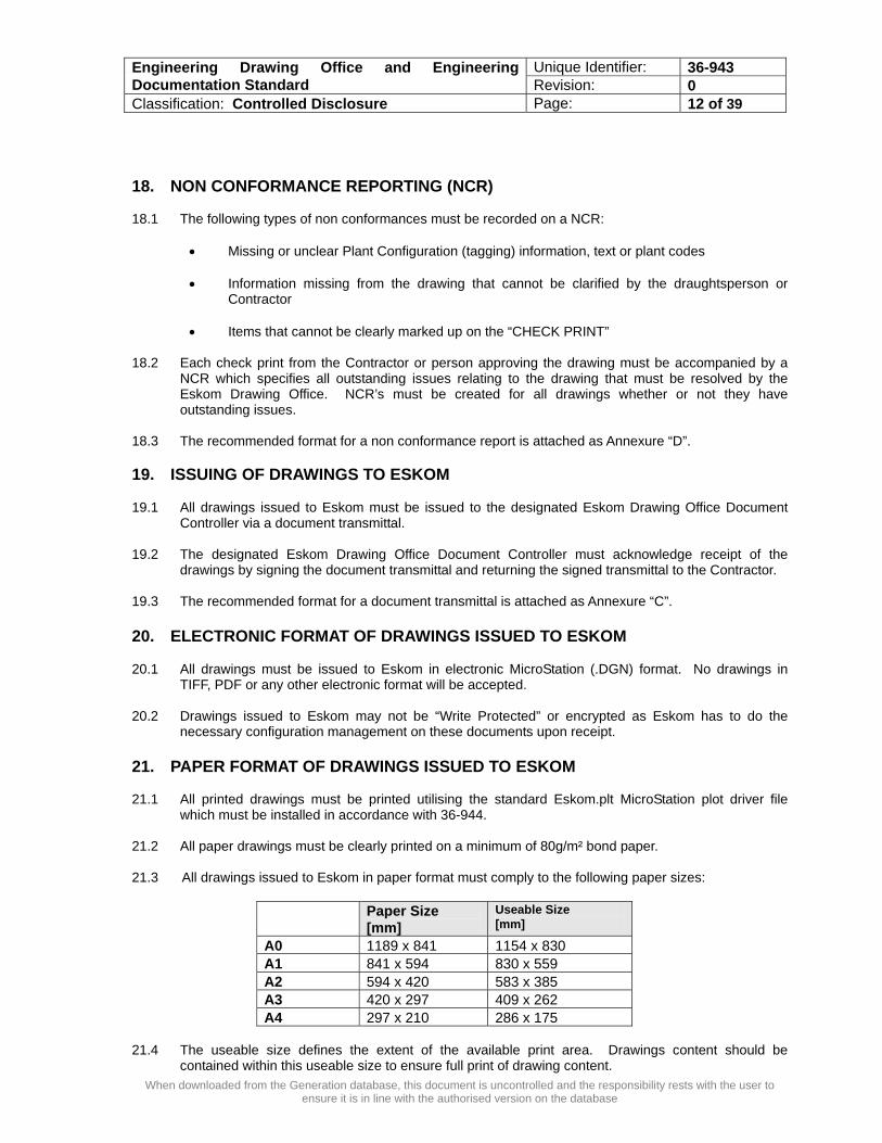
which must be installed in accordance with 36-944. 21.2 All paper drawings must be clearly printed on a minimum of 80g/m² bond paper. 21.3 All drawings issued to Eskom in paper format must comply to the following paper sizes:
Paper Size [mm]
Useable Size [mm]
A0 1189 x 841 1154 x 830 A1 841 x 594 830 x 559 A2 594 x 420 583 x 385 A3 420 x 297 409 x 262 A4 297 x 210 286 x 175
21.4 The useable size defines the extent of the available print area. Drawings content should be
contained within this useable size to ensure full print of drawing content.
Unique Identifier: 36-943 Engineering Drawing Office and Engineering Documentation Standard Revision: 0 Classification: Controlled Disclosure Page: 13 of 39
When downloaded from the Generation database, this document is uncontrolled and the responsibility rests with the user to ensure it is in line with the authorised version on the database
21.5 The standard Title Block files referred to in “SECTION B” and in 36-944 have been setup in
accordance with the useable sizes. 21.6 The standard seed file setup described in 36-944 defines the paper size to be utilised when inserting
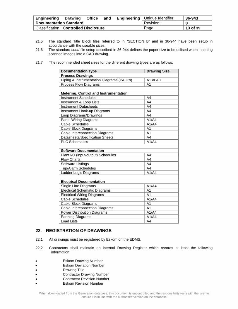
scanned images into a CAD drawing. 21.7 The recommended sheet sizes for the different drawing types are as follows:
Documentation Type Drawing Size Process Drawings Piping & Instrumentation Diagrams (P&ID’s) A1 or A0 Process Flow Diagrams A1 Metering, Control and Instrumentation Instrument Schedules A4 Instrument & Loop Lists A4 Instrument Datasheets A4 Instrument Hook-up Diagrams A4 Loop Diagrams/Drawings A4 Panel Wiring Diagrams A1/A4 Cable Schedules A1/A4 Cable Block Diagrams A1 Cable Interconnection Diagrams A1 Datasheets/Specification Sheets A4 PLC Schematics A1/A4 Software Documentation Plant I/O (input/output) Schedules A4 Flow Charts A4 Software Listings A4 Trip/Alarm Schedules A4 Ladder Logic Diagrams A1/A4 Electrical Documentation Single Line Diagrams A1/A4 Electrical Schematic Diagrams A1 Electrical Wiring Diagrams A1 Cable Schedules A1/A4 Cable Block Diagrams A1 Cable Interconnection Diagrams A1 Power Distribution Diagrams A1/A4 Earthing Diagrams A1/A4 Load Lists A4
22. REGISTRATION OF DRAWINGS 22.1 All drawings must be registered by Eskom on the EDMS. 22.2 Contractors shall maintain an internal Drawing Register which records at least the following
information: • Eskom Drawing Number • Eskom Deviation Number • Drawing Title • Contractor Drawing Number • Contractor Revision Number • Eskom Revision Number

Unique Identifier: 36-943 Engineering Drawing Office and Engineering Documentation Standard Revision: 0 Classification: Controlled Disclosure Page: 14 of 39
When downloaded from the Generation database, this document is uncontrolled and the responsibility rests with the user to ensure it is in line with the authorised version on the database
22.3 The Contractors drawing register must be made available to Eskom for audit on request.
23. REVISION CONTROL
23.1 Preliminary drawing revision numbers
23.1.1 Once a deviation has been registered, a preliminary drawing can be registered by Eskom Document Controller in accordance with the Eskom EDMS requirements.
23.1.2 Eskom preliminary revision numbers cannot be created or changed by Contractors. 23.1.3 When a preliminary drawing is first registered the revision number shall be “A” 23.1.4 Each revision of the drawing shall increase the alpha numeric revision number sequentially.
A B C etc…
23.1.5 When a drawing has an Eskom revision number (e.g. revision 2) the revision number shall be the
current Eskom revision number followed by a sequential alpha numeric revision number (e.g. ‘2A’).
23.1.6 Each revision of the drawing shall increase the revision number sequentially.
2A 2B 2C etc…
23.2 Drawing revision numbers 23.2.1 The Eskom revision number may only be revised by the designated Eskom Document Controller
once a deviation has been registered and closed out in accordance with the Eskom EDMS requirements.
23.2.2 Eskom revision numbers cannot be created or changed by Contractors. 23.2.3 Each revision of the drawing shall increase the revision number sequentially.
0 1 2 etc…
23.3 Revision information to be recorded in the Eskom section of the Title Block 23.3.1 The following information must be completed each time a drawing is revised by Eskom:
• Accredited drawing office abbreviation • Revision number • Date of revision • Short description of the revision • Draughtsperson’s initials • Checker’s initials • Authoriser’s initials • Approver’s initials • Codification approver’s initials
23.4 Revision information to be recorded in the Contractor section of the Title Block 23.4.1 The following information must be completed each time a drawing is revised by a Contractor:

Unique Identifier: 36-943 Engineering Drawing Office and Engineering Documentation Standard Revision: 0 Classification: Controlled Disclosure Page: 15 of 39
When downloaded from the Generation database, this document is uncontrolled and the responsibility rests with the user to ensure it is in line with the authorised version on the database
• Revision number • Date of revision • Short description of the revision • Draughtsperson’s initials • Designated Checker’s initials • Authoriser’s initials • Approver’s initials • Reference Drawings
24. CONTRACTOR INFORMATION BACKUP 24.1 The Contractor must ensure that all drawing data is backed up on a regular basis. 24.2 The Contractor must advise Eskom which back up methodology will be utilised and this back up
methodology must be approved by Eskom. 24.3 The maximum period between backups must not exceed 24 hours. 24.4 The backups must be carried out utilising an offsite rotating backup system to ensure that data-loss
is minimal should there be theft or equipment damage at Contractor’s site.
Unique Identifier: 36-943 Engineering Drawing Office and Engineering Documentation Standard Revision: 0 Classification: Controlled Disclosure Page: 16 of 39
When downloaded from the Generation database, this document is uncontrolled and the responsibility rests with the user to ensure it is in line with the authorised version on the database
SECTION B - CUSTOMISED CAD FILES 1. INSTALLATION OF CUSTOMISED CAD FILES FOR ALL DRAWINGS 1.1 Installation of the required customised Bentley MicroStation CAD files shall be done in accordance
with 36-944. 2. INSTALLATION OF CUSTOMISED CAD FILES FOR P&ID’s AND PFD’s
2.1 In addition to the files specified in Clause B1.0, the additional required software configuration shall be
done in accordance with 36-945 prior to commencing with draughting of P&ID’s and PFD’s in accordance with this standard.
3. INSTALLATION OF CUSTOMISED CAD FILES AND CELL LIBRARIES FOR
ELECTRICAL, DIAGRAMS/ DRAWINGS AND LADDER DIAGRAMS In addition to the files specified in Clause B1.0, the following additional Cell Libraries must be loaded into the configuration set-up:
3.1 For Electrical Drawings, the Eskom Standard Symbol Cell Library must be used, ie “Elect01.cel”.
The latest version of this cell library is obtainable from EED-Drawing Office. Users may not make any changes to the standard cell library. Should additional symbols be required, the EED-Drawing Office should be notified and a formal request registered using the form in Annexure “B” to have the symbols added. Symbols in this cell library are depicted as an Annexure “A” in 36-946.
3.2 For Ladder Diagrams (Ladder Logic Diagrams), the Standard Symbol Cell Library must be used, ie
“Ladder.Cel”. The latest version of this cell library is obtainable from EED-Drawing Office. Users may not make any changes to the standard cell library. Should additional symbols be required, the EED-Drawing Office should be notified and a formal request registered using the form in Annexure “B” to have the symbols added. Symbols in this cell library are depicted as an Annexure “B” in GWN1534.
4. INSTALLATION OF CUSTOMISED CAD FILES AND CELL LIBRARIES FOR
CONTROL AND INSTRUMENTATION DIAGRAMS/ DRAWINGS 4.1 In addition to the files specified in Clause B1.0, the additional C&I Cell Libraries must be loaded into
the configuration set-up. 4.2 For Control & Instrumentation Diagrams, the Standard Symbol Cell Library must be used, ie
“CandI.Cel”. The latest version of this cell library is obtainable from EED-rawing Office. Users may not make any changes to the standard cell library. Should additional symbols be required, the EED-Drawing Office should be notified and a formal request registered using the form in Annexure “B” to have the symbols added. Symbols in this cell library are depicted in Annexure “A” of 36-947.
5. INSTALLATION OF CUSTOMISED CAD FILES AND CELL LIBRARIES FOR
HYDRAULIC AND PNEUMATIC DIAGRAMS/ DRAWINGS 5.1 In addition to the files specified in Clause B1.0, the additional Hydraulic/Pneumatic Cell Libraries must
be loaded into the configuration set-up.
5.2 For Hydraulic and Pneumatic drawings/diagrams, the Standard Symbol Cell Library must be used, ie “Hydraulic.Cel”. The latest version of this cell library is obtainable from EED-Drawing Office. Users may not make any changes to the standard cell library. Should additional symbols be required, the EED-Drawing Office should be notified and a formal request registered using the form in “Annexure B” to have the symbols added. Symbols in this cell library are depicted in Appendix B of 36-945.
Unique Identifier: 36-943 Engineering Drawing Office and Engineering Documentation Standard Revision: 0 Classification: Controlled Disclosure Page: 17 of 39
When downloaded from the Generation database, this document is uncontrolled and the responsibility rests with the user to ensure it is in line with the authorised version on the database
SECTION C - ASSOCIATED ENGINEERING PROCESS INFORMATION/ DOCUMENTATION STANDARDS Where engineering methodology is applied for plant optimisation/management; or additional data/ information is generated that is relevant to the plant, appropriate steps shall be taken to capture this information in a format that will ensure that the information can be linked to the plant in question. To this effect, the following general requirements shall apply: 1. RELIABILITY CENTERED MAINTENANCE (RCM) Where an RCM exercise is undertaken on the plant, the following information shall be captured in an appropriate, year 2000 compliant format that is MicroSoft compatible (at least contained in, or exportable to MS Access/MS Excel):
1.1 History analysis of the plant in question
1.1.1 Equipment Being Analysed (AKZ/KKS Numbers for the Plant being analysed) 1.1.2 No of failures 1.1.3 Type of Failures 1.1.4 MTTR (Mean-Time-to-Repair) and MTBF (Mean-Time-Between-Failures) 1.1.5 Root Cause Analysis 1.1.6 IBI Barrier Failure Analysis 1.1.7 Reliability
1.2 Plant parameters 1.2.1 Plant design philosophy 1.2.2 Equipment performance Characteristics 1.2.3 Equipment Functional Analysis 1.2.4 Equipment Criticality Rating
1.3 Failure probability analysis and findings
1.4 Failure consequence analysis 1.4.1 Failure Modes 1.4.2 Failure Effects 1.4.3 Downtime – Scope and type of downtime 1.4.4 Consequences of the Downtime (Economic, Production, Safety & Other)
1.5 Maintenance Tasks 1.5.1 Tasks Identified 1.5.2 Task Execution Frequency 1.5.3 Plant State requirements for Execution (on-line, shutdown, outage, etc) 1.5.4 Need for Spares/Stockholding (Quantities, type, etc) 1.5.5 Responsibility/Accountability for Tasks
1.6 RCM Analysis Review & Sign-off documentation The above information shall be captured, as far as practically possible, down to component level, with the relevant KKS/AKZ plant code clearly indicated.
Unique Identifier: 36-943 Engineering Drawing Office and Engineering Documentation Standard Revision: 0 Classification: Controlled Disclosure Page: 18 of 39
When downloaded from the Generation database, this document is uncontrolled and the responsibility rests with the user to ensure it is in line with the authorised version on the database
2. HAZOP ANALYSIS Where a HAZOP Analysis exercise is undertaken on the plant, the following information shall be captured in an appropriate, year 2000 compliant format that is MicroSoft compatible (contained in; or exportable to MSAccess/MSExcel):
2.1 Plant Area and Equipment Analysed (AKZ and/or KKS Numbers listed)
2.2 Hazards Identified
2.2.1 Safety Hazards 2.2.2 Environmental Hazards 2.2.3 Health Hazards 2.2.4 Operability Problems
2.3 Design Review given the Hazards identified
2.4 Risk Mitigation Strategies for the Hazards
2.5 Risk Mitigation Responsibility/Accountability
2.6 HAZOP Analysis Review & Sign-off documentation The above information shall be captured, as far as practically possible, down to component level, with the relevant KKS/AKZ plant code clearly indicated.
3. SPECIFICATION FOR TECHNICAL DOCUMENTS The following specifications shall apply for all engineering technical documents submitted as part of engineering projects:
3.1 All Technical documents and the Document Register shall be provided in electronic format to the
Project Manager/relevant System Engineer for the plant in question. The number of electronic copies required will be stated in the NEC/Project Scope of Work (SoW); as well as the need for any documentation to be supplied in hardcopy format (eg Manuals). The format shall be in the MS Office Suite of software format and shall be supplied on CD/DVD ROM format.
3.2 Vendors/Contractors shall generate a Document Register listing all documents that will be submitted
during and/or on completion of the project SoW. This Register shall show, as a minimum:
3.2.1 Title of the Document 3.2.2 Vendor/Contractor Document Number 3.2.3 Eskom Unique Document Number (if required and/or pre-generated, this will be issued
as part of the “Request for Tender” (RFT) documentation). 3.2.4 Document Category (ie Drawing, Manual, etc) 3.2.5 Document Sub-Category (ie Datasheet, Electrical Block Diagram, Ladder Diagram,
Installation Manual, Training Manual etc) 3.2.6 Submission Due Date (as per Contract requirements) 3.2.7 Revision Number of the Document 3.2.8 Status of the document (ie Draft, Issued for construction, As-built, etc) 3.2.9 Document Approval Date 3.2.10 Transmittal Number 3.2.11 Distributed To/By 3.2.12 Deviation/Contract Number 3.2.13 Classification 3.2.14 Discipline 3.2.15 Impact Classification 3.2.16 Actions

Unique Identifier: 36-943 Engineering Drawing Office and Engineering Documentation Standard Revision: 0 Classification: Controlled Disclosure Page: 19 of 39
When downloaded from the Generation database, this document is uncontrolled and the responsibility rests with the user to ensure it is in line with the authorised version on the database
3.2.17 Plant Reference
• Plant Location • Plant Area • System/Sub-system • Equipment • Plant AKZ/KKS Code(s)
3.3 The Document Register shall be kept up to date by the EDMS Administrator at all times, and revision changes to documentation communicated to the relevant Project Manager on at least a monthly basis.
3.4 A Transmittal Note (Annexure “C”) shall be used to submit documents to Eskom Generation, and
must clearly state the purpose of the submission. 3.5 Where a document generated makes reference to plant systems, sub-systems and/or specific
components, the relevant plant AKZ/KKS Code shall be added to the document at the point of reference. These codes will be supplied by the plant codification officer (as per AKZ/KKS standards referred to in Section A, Point 6 of this standard).
3.6 Databases supplied as part of the contract/project documentation scope (eg a database containing
datasheet information) shall as a minimum be presented in MSAccess compatible format on CD/DVD ROM format, unless otherwise specified in the Contract SoW.
3.7 Spreadsheets shall be presented in MSExcel or MSOffice compatible format on CD/DVD ROM
Format. 3.8 For each project, the Vendor/Contractor shall supply a separate and complete set of documents
(referred to as “Manuals”) containing:
3.8.1 Installation Instructions 3.8.2 Maintenance and Operating Instructions 3.8.3 Training Materials/Manuals Where a large project is dealt with, consisting of groups of plant, systems or equipment, the
above documents shall be submitted for each plant, system, sub-system and equipment. 3.9 Initial submission of the documentation in 3.8 shall be made as specified in 3.2.6 of this document.
The necessary errors and deficiencies shall be rectified by the Vendor/Contractor after review by the appointed Project Manager/System Engineer. The final submission shall be made after all required data has been gathered, but shall not be later than 4 (four) weeks prior to commencement of installation of plant/equipment/ component(s).
3.10 The following General Requirements shall be met with the supply of Manuals (referred to in 3.8):
3.10.1 Installation, Maintenance and Operating Instructions shall be supplied as manuals in 2-D or 4-D Ring Binders. The 4-D Ring Binder shall always be used if the document contains more than 100 pages.
3.10.2 In all instances binders shall have spine sheets and a front overlay insert. 3.10.3 Coloured Dividers shall separate each section of the manual and shall be manufactured
from plastic and marked numerically to correspond with the index in the front of the manual in question.
3.10.4 Each section of the manual shall be sub-divided and indexed to facilitate quick referencing. 3.10.5 Drawings used/included in the manual shall be A4 or A3 size, unless larger size is
warranted for reasons of clarity. Drawings shall be able to be folded out without removal from the manual.
3.10.6 Drawings and charts larger than A3 size shall be folded and enclosed in a plastic pocket of A4 size of adequate strength.
Unique Identifier: 36-943 Engineering Drawing Office and Engineering Documentation Standard Revision: 0 Classification: Controlled Disclosure Page: 20 of 39
When downloaded from the Generation database, this document is uncontrolled and the responsibility rests with the user to ensure it is in line with the authorised version on the database
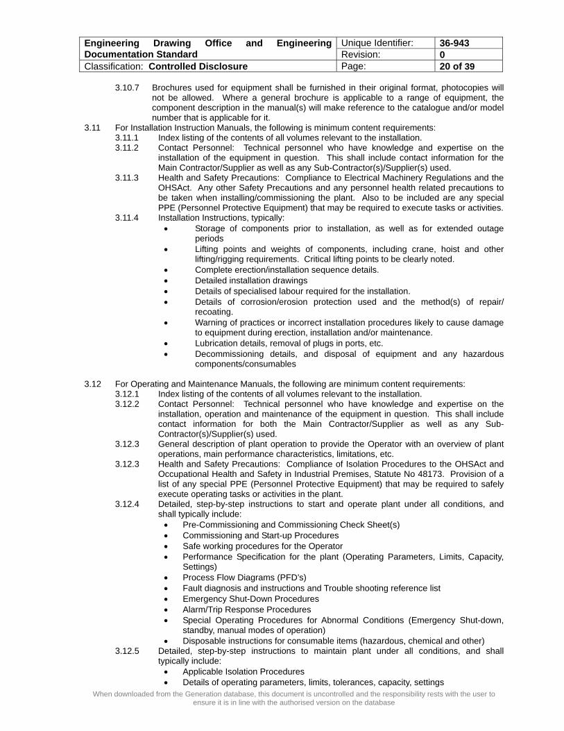
3.10.7 Brochures used for equipment shall be furnished in their original format, photocopies will not be allowed. Where a general brochure is applicable to a range of equipment, the component description in the manual(s) will make reference to the catalogue and/or model number that is applicable for it.
3.11 For Installation Instruction Manuals, the following is minimum content requirements: 3.11.1 Index listing of the contents of all volumes relevant to the installation. 3.11.2 Contact Personnel: Technical personnel who have knowledge and expertise on the
installation of the equipment in question. This shall include contact information for the Main Contractor/Supplier as well as any Sub-Contractor(s)/Supplier(s) used.
3.11.3 Health and Safety Precautions: Compliance to Electrical Machinery Regulations and the OHSAct. Any other Safety Precautions and any personnel health related precautions to be taken when installing/commissioning the plant. Also to be included are any special PPE (Personnel Protective Equipment) that may be required to execute tasks or activities.
3.11.4 Installation Instructions, typically: • Storage of components prior to installation, as well as for extended outage
periods • Lifting points and weights of components, including crane, hoist and other
lifting/rigging requirements. Critical lifting points to be clearly noted. • Complete erection/installation sequence details. • Detailed installation drawings • Details of specialised labour required for the installation. • Details of corrosion/erosion protection used and the method(s) of repair/
recoating. • Warning of practices or incorrect installation procedures likely to cause damage
to equipment during erection, installation and/or maintenance. • Lubrication details, removal of plugs in ports, etc. • Decommissioning details, and disposal of equipment and any hazardous
components/consumables
3.12 For Operating and Maintenance Manuals, the following are minimum content requirements: 3.12.1 Index listing of the contents of all volumes relevant to the installation. 3.12.2 Contact Personnel: Technical personnel who have knowledge and expertise on the
installation, operation and maintenance of the equipment in question. This shall include contact information for both the Main Contractor/Supplier as well as any Sub-Contractor(s)/Supplier(s) used.
3.12.3 General description of plant operation to provide the Operator with an overview of plant operations, main performance characteristics, limitations, etc.
3.12.3 Health and Safety Precautions: Compliance of Isolation Procedures to the OHSAct and Occupational Health and Safety in Industrial Premises, Statute No 48173. Provision of a list of any special PPE (Personnel Protective Equipment) that may be required to safely execute operating tasks or activities in the plant.
3.12.4 Detailed, step-by-step instructions to start and operate plant under all conditions, and shall typically include: • Pre-Commissioning and Commissioning Check Sheet(s) • Commissioning and Start-up Procedures • Safe working procedures for the Operator • Performance Specification for the plant (Operating Parameters, Limits, Capacity,
Settings) • Process Flow Diagrams (PFD’s) • Fault diagnosis and instructions and Trouble shooting reference list • Emergency Shut-Down Procedures • Alarm/Trip Response Procedures • Special Operating Procedures for Abnormal Conditions (Emergency Shut-down,
standby, manual modes of operation) • Disposable instructions for consumable items (hazardous, chemical and other)
3.12.5 Detailed, step-by-step instructions to maintain plant under all conditions, and shall typically include: • Applicable Isolation Procedures • Details of operating parameters, limits, tolerances, capacity, settings
Unique Identifier: 36-943 Engineering Drawing Office and Engineering Documentation Standard Revision: 0 Classification: Controlled Disclosure Page: 21 of 39
When downloaded from the Generation database, this document is uncontrolled and the responsibility rests with the user to ensure it is in line with the authorised version on the database
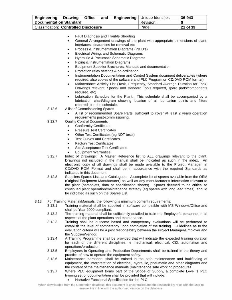
• Fault Diagnosis and Trouble Shooting • General Arrangement drawings of the plant with appropriate dimensions of plant,
interfaces, clearances for removal etc • Process & Instrumentation Diagrams (P&ID’s) • Electrical Wiring, and Schematic Diagrams • Hydraulic & Pneumatic Schematic Diagrams • Piping & Instrumentation Diagrams • Equipment Supplier Brochures, Manuals and documentation • Protection relay settings & co-ordination • Instrumentation Documentation and Control System document deliverables (where
required, also copies of the software and PLC Program on CD/DVD ROM format) • Maintenance Activity List (Task, Frequency, Standard Average Duration for Task,
Drawings relevant, Special and standard Tools required, spare parts/components required, etc)
• Lubrication Schedule for the Plant. This schedule shall be accompanied by a lubrication chart/diagram showing location of all lubrication points and filters referred to in the schedule.
3.12.6 A list of Commissioning Spares • A list of recommended Spare Parts, sufficient to cover at least 2 years operation
requirements post-commissioning. 3.12.7 Quality Control Documents
• Conformity Certificates • Pressure Test Certificates • Other Test Certificates (eg NDT tests) • Test Curves and Certificates • Factory Test Certificates • Site Acceptance Test Certificates • Equipment Warranties
3.12.7 Index of Drawings: A Master Reference list to ALL drawings relevant to the plant. Drawings not included in the manual shall be indicated as such in the index. An electronic copy of all drawings shall be made available to the Project Manager, in CD/DVD ROM Format and shall be in accordance with the required Standards as indicated in this document.
3.12.8 Suppliers Spares Lists and Catalogues: A complete list of spares available from the OEM (Original Equipment Manufacturer) as well as any manufacturer’s information relevant to the plant (pamphlets, data or specification sheets). Spares deemed to be critical to continued plant operation/maintenance strategy (eg spares with long lead times), should be indicated as such on the Spares List.
3.13 For Training Material/Manuals, the following is minimum content requirements:
3.13.1 Training material shall be supplied in software compatible with MS Windows/Office and shall be Year 2000 compliant.
3.13.2 The training material shall be sufficiently detailed to train the Employer’s personnel in all aspects of the plant operations and maintenance.
3.13.3 Training shall be outcome based and competency evaluations will be performed to establish the level of competency upon completion of the training. Guidelines as to the evaluation criteria will be a joint responsibility between the Project Manager/Employer and the Supplier/Vendor.
3.13.4 A Training Programme shall be provided that will indicate the expected training duration for each of the different disciplines, ie mechanical, electrical, C&I, automation and operations/production.
3.13.5 Employees in Operating and Production Departments shall be trained in the theory and practice of how to operate the equipment safely.
3.13.6 Maintenance personnel shall be trained in the safe maintenance and faultfinding of equipment, the interpretation of electrical, hydraulic, pneumatic and other diagrams and the content of the maintenance manuals (maintenance safe working procedures)
3.13.7 Where PLC equipment forms part of the Scope of Supply, a complete Level 1 PLC training set of documentation shall be provided that will include: • Narrative Functional Specification for the PLC

Unique Identifier: 36-943 Engineering Drawing Office and Engineering Documentation Standard Revision: 0 Classification: Controlled Disclosure Page: 22 of 39
When downloaded from the Generation database, this document is uncontrolled and the responsibility rests with the user to ensure it is in line with the authorised version on the database
• Fully documented hard copy print-out of the PLC program (“As Built”/ Delivered) • Electronic Copy of the PLC Program • Copy of Logic Diagrams as applicable • Training on the PLC Software provided on which the PLC Program is running.
4. ARCHIVING AND RECORDS STORAGE OF DRAWINGS AND ENGINEERING INFORMATION AND DOCUMENTATION
All storage and archiving of drawing records and engineering documentation/information shall be in line with EPC0001 (Eskom Documentation Management Procedure), 36-1 (Standard for Management System Documents, Correspondence and Records) and 36-2 (Writing And Controlling Management System Documents).
5. DRAWING META DATA REQUIRED 5.1 The following drawing meta-data are mandatory for capture with each drawing generated:
META DATA Example Eskom Drawing Number: 0.57/12342 Full Drawing Title: Duvha Power Station, Coal Milling Plant, Service Air
P&ID Drawing Sheet: 2 of 5 Sub Sheet: - Latest Revision: 12 Sheet Print Size: A0 Information Classification: Level 3 – Controlled Disclosure Design Classification: Level 2 Discipline: Mechanical Drawing Status: As Built & Approved Authorised Date: 2000/01/10 Authorised By: D van Rensburg – D&S Manager Functional Responsibility (Information Owner):
Boiler Plant Engineering Section Duvha Power Station
0.57/6789 Unit #1 Boiler House Floor Lay-Out 0.57/14555 Milling Plant Service Air Supply
Compressor
Cross Reference Drawing No & Title
0.57/1433 Coal Milling Plant General Arrangement Relevant Plant KKS/AKZ Code(s) 01NM30D050
01NM20D050
Manufacturer’s/OEM Name: Babcock & Wilcox Manufacturers/OEM Drawing No: 1433/13257889 Construction Contract No: OPY11282 Media Format: MicroStation – DGN Index Reference: C 4.1 Power Station/BU/Site: Duvha Power Station Station ID: 0.57 Office of Origin: Duvha Site Drawing Office Location of Original: MWP Archives Retention Period: Station Life Superseded By Drawing No: (eg if drawings were combined to become 1) Drawing Review Date: 2010/03/31 Drawing Master Copies Distributed To:
Duvha Power Station CED

Unique Identifier: 36-943 Engineering Drawing Office and Engineering Documentation Standard Revision: 0 Classification: Controlled Disclosure Page: 23 of 39
When downloaded from the Generation database, this document is uncontrolled and the responsibility rests with the user to ensure it is in line with the authorised version on the database
Latest Revision Originator: Duvha PS -24 Site Modification/Deviation No: DEV1432-B-1 MWP Work Request No: DUV.001.004
5.2 This drawing meta-data shall be captured in electronic format in the EDMS and/or Plant Engineering System (Bentley/Intergraph) and shall have a record and audit trail associated for each drawing that exists.
5.3 The following meta-data must be captured for engineering related documentation:
META DATA Example Eskom Document Number: 200-12342 Previous Unique Doc Number EE-Spec0145 Full Document Title: Duvha Power Station, Coal Milling Plant, Service Air
P&ID Document Category: Manual Document Sub-Category:: Operating Latest Revision: 4 Compiled By: HH Smith Date of Publication 2007-12-23 Document Status: Approved Authorised Date: 2000/01/10 Authorised By: D van Rensburg – D&S Manager Information Classification: Level 3 – Controlled Disclosure Design Classification: Level 2 Discipline: Operating Functional Responsibility (Information Owner):
Boiler Plant Engineering Section Duvha Power Station 200-342225 Milling Plant Operating Philosophy 200-3554 Milling Plant Service Air Supply
Compressor
Cross Reference Document No & Title
0.57/1433 Coal Milling Plant General Arrangement Relevant Plant KKS/AKZ Code(s) 01NM30D050
01NM20D050
Manufacturer’s/OEM Name: Babcock & Wilcox Manufacturers/OEM Document No: 1433/13257889 Construction Contract No: OPY11282 Document Transmittal No: OPY11282/2445 Media Format: MS Word (DOC)
Duvha Boiler Plant Manager Document Master Copies Distributed To: Duvha Site Library Location of Original: EED – Engineering Support Review Date: 2010-03-15 Retention Period: Station Life Destruction Date: Not Applicable Superseded By Drawing No: Not Applicable Archiving Requirements: Retain All Previous Revisions Archiving Format: Electronic Copy Only
6. DISASTER RECOVERY AND BUSINESS CONTINUITY PLANNING FOR DRAWINGS AND ENGINEERING INFORMATION
6.1 Appropriate Disaster Recovery Procedures shall be put in place by the Generation Business Unit as
well as Eskom Drawing Office and Contractors to ensure availability of plant information and drawings at all times.

Unique Identifier: 36-943 Engineering Drawing Office and Engineering Documentation Standard Revision: 0 Classification: Controlled Disclosure Page: 24 of 39
When downloaded from the Generation database, this document is uncontrolled and the responsibility rests with the user to ensure it is in line with the authorised version on the database
6.2 Appropriate Business Continuity Plans shall be put in place by the Generation Business Unit as well as Eskom Drawing Office and Contractors to ensure operability of plant and access to appropriate engineering drawings and information during disasters.
6.3 Adherence to the required Information Security Best Practice shall be ensured at all times,
specifically keeping Anti-Virus Software Signatures up to date and loading the required software patches on both MicroSoft as well as Bentley Software as soon as they become available. This is considered critical on IT infrastructure utilised to store, manage and archive drawings and related engineering information.
6.4 A hardcopy of the drawing meta-data shall be available at all times and may not be older than 6
months at any given period of time (for BCP purposes). 6.5 The original, latest revision approved drawing shall be submitted to MWP for capture on microfilm
and converted to electronic format (where required). This drawing will be considered the latest approved version of the drawing in instances where an information availability disaster is declared and will stay in force until Disaster Recovery is complete.
SECTION D - ANNEXURES
ANNEXURE A DRAWING WORK FLOW ANNEXURE B DRAWING REQUISITION ANNEXURE C DOCUMENT TRANSMITTAL ANNEXURE D NON CONFORMANCE REPORT (NCR) ANNEXURE E STANDARD LAYERS AND COLOURS ANNEXURE F EXAMPLES OF STAMPS ANNEXURE G DRAWING TITLE BLOCKS ANNEXURE H STANDARD CHECKLIST FOR DRAWINGS
ANNEXURE I NON-DISCLOSURE AGREEMENT

Unique Identifier: 36-943 Engineering Drawing Office and Engineering Documentation Standard Revision: 0 Classification: Controlled Disclosure Page: 25 of 39
When downloaded from the Generation database, this document is uncontrolled and the responsibility rests with the user to ensure it is in line with the authorised version on the database
1.11 Sheet 2 of 3 ESKOM
Drawing Office
1.12 Sheet 3 of 3
Contractor Drawing Office
ANNEXURE ‘A’ DRAWING WORK FLOW
1.1 Deviation Request
for Drawing Creation/Revision
1.2 Deviation Process
Allocate Responsible Person
1.4 Responsible Person
Request Drawing via drawing requisition
YESNO
1.3 Create New Drawing ?
1.8 Responsible Person Request
Drawing Number via drawing requisition
1.6 Central Controller Issue Drawing
via drawing transmittal
1.9 Central Controller Issue New Drawing Number
via EDMS
1.5 Create Drawing Update Environment Central Controller book out drawing as new revision and reflect drawing status
in EDMS as “under review”
1.10 Responsible Person
ESKOM or Contractor
Unique Identifier: 36-943 Engineering Drawing Office and Engineering Documentation Standard Revision: 0 Classification: Controlled Disclosure Page: 26 of 39
When downloaded from the Generation database, this document is uncontrolled and the responsibility rests with the user to ensure it is in line with the authorised version on the database
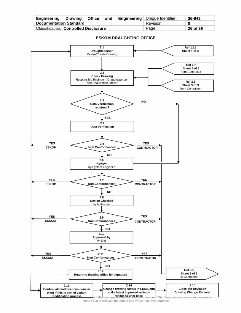
ESKOM DRAUGHTING OFFICE
2.2 Check Drawing
Responsible Engineer / Draughtsperson and Codification Officer
YES
2.4 Data Verification
2.6 Review
by System Engineer
2.10 Approved by
Pr Eng
YES
2.8 Design Checked
by Authoriser
NO
2.3 Data Verification
required ?
2.5 Non Conformances
NO
NO
2.9 Non Conformances
2.1 Draughtsperson
Revise/Create Drawing
Ref 1.11 Sheet 1 of 3
Ref 3.7 Sheet 3 of 3
from Contractor
Ref 3.1 Sheet 3 of 3 to Contractor
ESKOM
YES
ESKOM
YES
ESKOM
YESCONTRACTOR
YESCONTRACTOR
Ref 3.8 Sheet 3 of 3
from Contractor
YES
CONTRACTOR
2.11 Non Conformances
2.12 Return to drawing office for signature
NO
2.7 Non Conformances
YES
ESKOM
YESCONTRACTOR
NO
2.13 Confirm all modifications done in
plant if this is part of a plant modification process
2.14 Change drawing status in EDMS and
make latest approved revision visible to user base
2.15 Close out Deviation
Drawing Change Request

Unique Identifier: 36-943 Engineering Drawing Office and Engineering Documentation Standard Revision: 0 Classification: Controlled Disclosure Page: 27 of 39
When downloaded from the Generation database, this document is uncontrolled and the responsibility rests with the user to ensure it is in line with the authorised version on the database
CONTRACTOR DRAUGHTING OFFICE
3.2 Check Drawing
Responsible Engineer or Draughtsperson
NO
YES
YES 3.3
Non Conformances
3.6 Non Conformances
3.1 Contractor Draughtsperson
Revise/Create Drawing
Ref 2.2 Sheet 2 of 3 to ESKOM
Sheet 2 of 3 Checked Drawing
from ESKOM
Ref 1.12 Sheet 1 of 3 from ESKOM
Ref 2.2 Sheet 2 of 3 to ESKOM
3.8 Issue Drawing to ESKOM
for checking via Drawing Transmittal
YES 3.5
Data Verification
3.4 Data Verification
required ?
NO
NO
3.7 NCR Required
YES
NO

Unique Identifier: 36-943 Engineering Drawing Office and Engineering Documentation Standard Revision: 0 Classification: Controlled Disclosure Page: 28 of 39
When downloaded from the Generation database, this document is uncontrolled and the responsibility rests with the user to ensure it is in line with the authorised version on the database
ANNEXURE ‘B’
REQUISITION NO
DATE
DRAWING
REQUISITION
REQUESTED BY REQUESTED FROM
NAME COMPANY VENDOR NO ADDRESS CONTACT TEL: E-MAIL:
ESKOM POWER STATION ADDRESS CONTACT TEL: E-MAIL:
ESKOM PROJECT NUMBER
CONTRACTOR REF NUMBER
QTY DRAWING NO DRAWING TITLE REVISION
FORMAT REQUIRED COMMENTS PAPER ELECTRONIC REQUESTED BY:
NAME DESIGNATION/COMPANY DATE SIGNATURE
AUTHORISED BY: NAME DESIGNATION DATE SIGNATURE
ISSUED BY: NAME DESIGNATION DATE SIGNATURE
Unique Identifier: 36-943 Engineering Drawing Office and Engineering Documentation Standard Revision: 0 Classification: Controlled Disclosure Page: 29 of 39
When downloaded from the Generation database, this document is uncontrolled and the responsibility rests with the user to ensure it is in line with the authorised version on the database
ANNEXURE ‘C’
TRANSMITTAL NO
DATE
DOCUMENT TRANSMITTAL
ISSUED BY ISSUED TO NAME COMPANY VENDOR NO ADDRESS CONTACT TEL: E-MAIL:
ESKOM UNIT ADDRESS CONTACT TEL: E-MAIL:
ESKOM PROJECT NUMBER
CONTRACTOR REF NUMBER
DRAWING NO DRAWING TITLE REVISION
TRANSMITTED FOR: CHECKING APPROVAL AUTHORISATION QUOTATION CONSTRUCTION OTHER:
ISSUED BY: NAME DESIGNATION/COMPANY DATE SIGNATURE
RECEIVED BY: NAME DESIGNATION DATE SIGNATURE

Unique Identifier: 36-943 Engineering Drawing Office and Engineering Documentation Standard Revision: 0 Classification: Controlled Disclosure Page: 30 of 39
When downloaded from the Generation database, this document is uncontrolled and the responsibility rests with the user to ensure it is in line with the authorised version on the database
ANNEXURE ‘D’
DEVIATION NUMBER
ESKOM PROJECT NUMBER
NON
CONFORMANCE REPORT
ISSUED BY ISSUED TO
NAME COMPANY VENDOR NO ADDRESS CONTACT TEL: E-MAIL:
ESKOM UNIT ADDRESS CONTACT TEL: E-MAIL:
DRAWING NO DRAWING TITLE REVISION
ITEM NO
DESCRIPTION OF NON CONFORMANCE
ISSUED BY: NAME DESIGNATION/COMPANY DATE SIGNATURE
RECEIVED BY: NAME DESIGNATION DATE SIGNATURE
Unique Identifier: 36-943 Engineering Drawing Office and Engineering Documentation Standard Revision: 0 Classification: Controlled Disclosure Page: 31 of 39
When downloaded from the Generation database, this document is uncontrolled and the responsibility rests with the user to ensure it is in line with the authorised version on the database
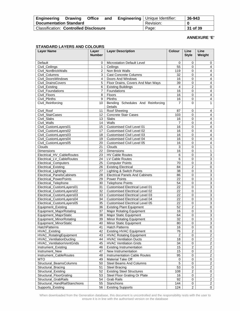
ANNEXURE ‘E’ STANDARD LAYERS AND COLOURS Layer Name Layer
Number Layer Description Colour Line
Style Line Weight
Default 0 Microstation Default Level 0 0 0 Civil_Ceilings 1 Ceilings 55 0 4 Civil_NonBrickWalls 2 Non Brick Walls 119 0 4 Civil_Columns 3 Cast Concrete Columns 32 0 4 Civil_DoorsWindows 4 Doors And Windows 16 0 4 Civil_DrainsCovers 5 Floor Drains, Covers And Man Ways 39 0 4 Civil_Existing 6 Existing Buildings 4 2 0 Civil_Foundations 7 Foundations 16 0 4 Civil_Floors 8 Floors 16 0 4 Civil_Plinths 9 Plinths 16 0 4 Civil_Reinforcing 10 Bending Schedules And Reinforcing
Details 7 0 1
Civil_Roof 11 Roof Sheeting 87 0 4 Civil_StairCases 12 Concrete Stair Cases 103 0 4 Civil_Slabs 13 Slabs 16 0 4 Civil_Walls 14 Walls 7 0 4 Civil_CustomLayers01 15 Customised Civil Level 01 16 0 4 Civil_CustomLayers02 17 Customised Civil Level 02 16 0 4 Civil_CustomLayers03 18 Customised Civil Level 03 16 0 4 Civil_CustomLayers04 19 Customised Civil Level 04 16 0 4 Civil_CustomLayers05 20 Customised Civil Level 05 16 0 4 Clouds 21 Clouds 3 0 1 Dimensions 22 Dimensions 16 0 1 Electrical_HV_CableRoutes 23 HV Cable Routes 6 0 3 Electrical_LV_CableRoutes 24 LV Cable Routes 6 0 3 Electrical_Computers 25 Computer Points 70 0 3 Electrical_Existing 26 Existing Electrical 84 2 0 Electrical_Lightings 27 Lighting & Switch Points 38 0 3 Electrical_PanelsCabinets 28 Electrical Panels And Cabinets 86 0 3 Electrical_PowerPoints 29 Power Points 22 0 3 Electrical_Telephone 30 Telephone Points 54 0 3 Electrical_CustomLayers01 31 Customised Electrical Level 01 22 0 3 Electrical_CustomLayers02 32 Customised Electrical Level 02 22 0 3 Electrical_CustomLayers03 33 Customised Electrical Level 03 22 0 3 Electrical_CustomLayers04 34 Customised Electrical Level 04 22 0 3 Electrical_CustomLayers05 35 Customised Electrical Level 05 22 0 3 Equipment_Existing 36 Existing Plant Equipment 52 2 0 Equipment_MajorRotating 37 Major Rotating Equipment 16 0 3 Equipment_MajorStatic 38 Major Static Equipment 64 0 3 Equipment_MinorRotating 39 Minor Rotating Equipment 32 0 3 Equipment_MinorStatic 40 Minor Static Equipment 80 0 3 HatchPatterns 41 Hatch Patterns 16 0 0 HVAC_Existing 42 Existing HVAC Equipment 76 2 0 HVAC_RotatingEquipment 43 HVAC Rotating Equipment 2 0 2 HVAC_VentilationDucting 44 HVAC Ventilation Ducts 18 0 2 HVAC_VentilationVentGrids 45 HVAC Ventilation Grids 34 0 2 Instrument_Existing 46 Existing Instrumentation 15 2 2 Instrument_New 47 New Instrumentation 15 0 2 Instrument_CableRoutes 48 Instrumentation Cable Routes 95 0 2 MTO 49 Material Take Off 0 0 0 Structural_BeamsColumns 50 Steel Beams And Columns 5 0 2 Structural_Bracing 51 Steel Bracing 53 0 2 Structural_Existing 52 Existing Steel Structures 108 2 0 Structural_FloorGrating 53 Steel Floor Grating Or Plate 16 0 2 Structural_GrabRails 54 Grab Rails 92 0 2 Structural_HandRailStanchions 55 Stanchions 144 0 2 Supports_Existing 56 Existing Supports 124 2 0
Unique Identifier: 36-943 Engineering Drawing Office and Engineering Documentation Standard Revision: 0 Classification: Controlled Disclosure Page: 32 of 39
When downloaded from the Generation database, this document is uncontrolled and the responsibility rests with the user to ensure it is in line with the authorised version on the database
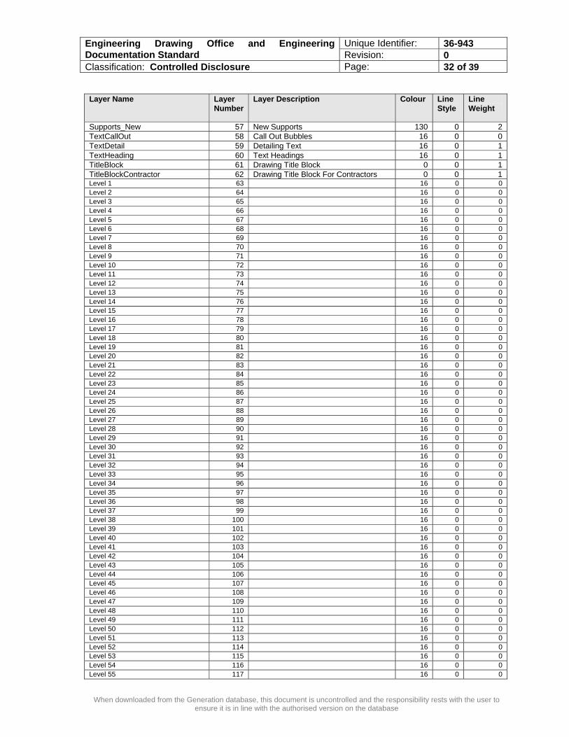
Layer Name Layer
Number Layer Description Colour Line
Style Line Weight
Supports_New 57 New Supports 130 0 2 TextCallOut 58 Call Out Bubbles 16 0 0 TextDetail 59 Detailing Text 16 0 1 TextHeading 60 Text Headings 16 0 1 TitleBlock 61 Drawing Title Block 0 0 1 TitleBlockContractor 62 Drawing Title Block For Contractors 0 0 1 Level 1 63 16 0 0 Level 2 64 16 0 0 Level 3 65 16 0 0 Level 4 66 16 0 0 Level 5 67 16 0 0 Level 6 68 16 0 0 Level 7 69 16 0 0 Level 8 70 16 0 0 Level 9 71 16 0 0 Level 10 72 16 0 0 Level 11 73 16 0 0 Level 12 74 16 0 0 Level 13 75 16 0 0 Level 14 76 16 0 0 Level 15 77 16 0 0 Level 16 78 16 0 0 Level 17 79 16 0 0 Level 18 80 16 0 0 Level 19 81 16 0 0 Level 20 82 16 0 0 Level 21 83 16 0 0 Level 22 84 16 0 0 Level 23 85 16 0 0 Level 24 86 16 0 0 Level 25 87 16 0 0 Level 26 88 16 0 0 Level 27 89 16 0 0 Level 28 90 16 0 0 Level 29 91 16 0 0 Level 30 92 16 0 0 Level 31 93 16 0 0 Level 32 94 16 0 0 Level 33 95 16 0 0 Level 34 96 16 0 0 Level 35 97 16 0 0 Level 36 98 16 0 0 Level 37 99 16 0 0 Level 38 100 16 0 0 Level 39 101 16 0 0 Level 40 102 16 0 0 Level 41 103 16 0 0 Level 42 104 16 0 0 Level 43 105 16 0 0 Level 44 106 16 0 0 Level 45 107 16 0 0 Level 46 108 16 0 0 Level 47 109 16 0 0 Level 48 110 16 0 0 Level 49 111 16 0 0 Level 50 112 16 0 0 Level 51 113 16 0 0 Level 52 114 16 0 0 Level 53 115 16 0 0 Level 54 116 16 0 0 Level 55 117 16 0 0

Unique Identifier: 36-943 Engineering Drawing Office and Engineering Documentation Standard Revision: 0 Classification: Controlled Disclosure Page: 33 of 39
When downloaded from the Generation database, this document is uncontrolled and the responsibility rests with the user to ensure it is in line with the authorised version on the database
Layer Name Layer Number
Layer Description Colour Line Style
Line Weight
Level 56 118 16 0 0 Level 57 119 16 0 0 Level 58 120 16 0 0 Level 59 121 16 0 0 Level 60 122 16 0 0 Level 61 123 16 0 0 Level 62 124 16 0 0 Level 63 125 16 0 0
ANNEXURE ‘F’

Unique Identifier: 36-943 Engineering Drawing Office and Engineering Documentation Standard Revision: 0 Classification: Controlled Disclosure Page: 34 of 39
When downloaded from the Generation database, this document is uncontrolled and the responsibility rests with the user to ensure it is in line with the authorised version on the database
EXAMPLES OF STAMPS
Controlled Copy Issued To
Date of Issue:
CHECK PRINT Signature Date
ANNEXURE ‘G’
SUPERSEDED
CANCELLED

Unique Identifier: 36-943 Engineering Drawing Office and Engineering Documentation Standard Revision: 0 Classification: Controlled Disclosure Page: 35 of 39
When downloaded from the Generation database, this document is uncontrolled and the responsibility rests with the user to ensure it is in line with the authorised version on the database
Eskom Title Block
The Title Block used by Eskom Enterprises Division, is also acceptable for upgrade/modification or new-build projects.
Drawing Classification in accordance with clause A.11.0
Revision No
Accredited drawing office abbreviation
Date of revision
Description of revision
Checked by: Responsible Engineer or Draughts person
Authorised by: Designer
Power Station Name (e.g. Lethabo Power Station) Unit Number (e.g. Unit 01)
System Plant Group (AKS or KKS )/ Description Description 2
Drawing Type
Drawing Number in accordance with GGS 0445
Drawing Scale
Codification done by: Codification Officer
Approved by: Pr Eng including Pr. Eng Registration No
Revision No

Unique Identifier: 36-943 Engineering Drawing Office and Engineering Documentation Standard Revision: 0 Classification: Controlled Disclosure Page: 36 of 39
When downloaded from the Generation database, this document is uncontrolled and the responsibility rests with the user to ensure it is in line with the authorised version on the database
Contractor Title Block
ANNEXURE ‘H’
Revision No
Date of revisionDrawn by: Draughts person
Checked by: Responsible Engineer or Draughts person
Authorised by: Designer
Approved by: Pr Eng including Pr Eng Registration No
Company Logo and contact details
Description of revision

Unique Identifier: 36-943 Engineering Drawing Office and Engineering Documentation Standard Revision: 0 Classification: Controlled Disclosure Page: 37 of 39
When downloaded from the Generation database, this document is uncontrolled and the responsibility rests with the user to ensure it is in line with the authorised version on the database
CHECKLIST NO
DATE
DRAWING CHECKLIST
Drawing No Revision Date
No Description Complies Does Not Comply Eskom section of the title block:
Power Station Name Unit number System Plant Group (AKS or KKS )/ Description Drawing Type Drawing Number in accordance with GGS 0445 Drawing classification in accordance with clause A.11.0 Drawing Scale Accredited drawing office abbreviation (if revised by Eskom) Revision No Date of revision Description of revision Drawn by: Draughtsperson Checked by: Responsible Engineer or Draughtsperson Authorised by: Designer Codification by: Codification Officer
1
Approved by: Pr Eng including ECSA Pr Eng Registration No Contractor section of the title block where applicable: Company information including contract details Revision No Date of revision Description of revision Drawn by: Draughts person Checked by: Responsible Engineer or Draughts person Authorised by: Designer
2
Approved by: Pr Eng including ECSA Pr Eng Registration No 3 All applicable reference drawings are indicated in the reference drawings
section.
4 All applicable notes are indicated in the notes drawing section. Text:
• in accordance with the standard
• spelling is correct
• standard approved abbreviations are used and applied consistently
5
• words spelled out where possible Dimensions:
• in accordance with the standard
• indicated showing clear intent
6
• do not overlap with other drawing elements The following drawing symbology in accordance with the standard:
• lines
• layers
7
• levels 8 Drawing is legible with no overlapping lines 9 All marked up items have been incorporated as required
CHECKED BY: NAME DESIGNATION/COMPANY DATE SIGNATURE
RECEIVED BY: NAME DESIGNATION DATE SIGNATURE
ANNEXURE ‘I’

Unique Identifier: 36-943 Engineering Drawing Office and Engineering Documentation Standard Revision: 0 Classification: Controlled Disclosure Page: 38 of 39
When downloaded from the Generation database, this document is uncontrolled and the responsibility rests with the user to ensure it is in line with the authorised version on the database
Please be advised that the drawing(s) attached, (0.63/ Rev ) provided to you, is considered the intellectual property of Eskom and Eskom ……………. Power Station. This data/information is made available solely for quotation/…………… purposes, and may not be reproduced, copied or made available to any third party without prior consent from the Power Station manager. All information referred to herein need to be returned to Eskom ………………….Power Station Drawing office on completion of the project. Signature: …………………………. Date …………………………. M-band Manager ACKNOWLEDGEMENT OF RECEIPT: Signature: ………………………….. Date ………………………… Supplier
Intellectual Property Protection Company VAT No: Eskom Vendor No:
NON-DISCLOSURE AGREEMENT FORM EXAMPLE
Revisions Information
Memo
(ID No.: )
………………. Power Station Tel +27 …………………… Fax +27 ……………………

Unique Identifier: 36-943 Engineering Drawing Office and Engineering Documentation Standard Revision: 0 Classification: Controlled Disclosure Page: 39 of 39
When downloaded from the Generation database, this document is uncontrolled and the responsibility rests with the user to ensure it is in line with the authorised version on the database
Date Rev. Remarks
September 2007 0 Revised the requirements for Generation and aligned it with latest drawing office best practice and draughting software requirements. At the same time converted the standard into the Eskom document template, as per the decision of the Generation Document Working group. This standard was previously known as GGS0991, Revision 0.