Embed Size (px)
Citation preview

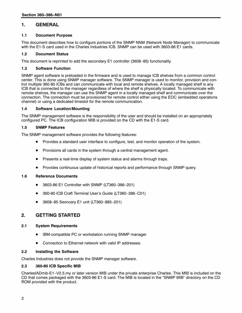
Section 360–386–N01
Equipment Issue 1Printing 2, October 2004Telecommunications Group
�2004 Charles Industries Ltd.All rights reserved. Printed in United States of America.The availability of features and technical specifications herein subject to change without notice.
Page 1 of 27
360-80 SNMP Network Node Manager (NNM) Setup GuideCONTENTS PAGE
Part 1. GENERAL 2. . . . . . . . . . . . . . . . . . . . . . . . . . . . . . . . . . . . . . . . . . . . . . . . . . . . . . . . . . . . . . . . . . . . . . . . . . . . . Part 2. GETTING STARTED 2. . . . . . . . . . . . . . . . . . . . . . . . . . . . . . . . . . . . . . . . . . . . . . . . . . . . . . . . . . . . . . . . . . . . Part 3. ICB COMMUNICATION CONFIGURATION 3. . . . . . . . . . . . . . . . . . . . . . . . . . . . . . . . . . . . . . . . . . . . . . . . Part 4. TRAPS 6. . . . . . . . . . . . . . . . . . . . . . . . . . . . . . . . . . . . . . . . . . . . . . . . . . . . . . . . . . . . . . . . . . . . . . . . . . . . . . . . Part 5. CONTROLLING AND CHANGING ICB CONFIGURATION 7. . . . . . . . . . . . . . . . . . . . . . . . . . . . . . . . . . . Part 6. TECHNICAL ASSISTANCE 8. . . . . . . . . . . . . . . . . . . . . . . . . . . . . . . . . . . . . . . . . . . . . . . . . . . . . . . . . . . . . . Part 7. MIB OBJECT IDENTIFIER 8. . . . . . . . . . . . . . . . . . . . . . . . . . . . . . . . . . . . . . . . . . . . . . . . . . . . . . . . . . . . . . .
Figure 1. 360-80 CD ROM
Section 360–386–N01
�
1. GENERAL
1.1 Document Purpose
This document describes how to configure portions of the SNMP NNM (Network Node Manager) to communicatewith the E1-S card used in the Charles Industries ICB. SNMP can be used with 3603-86 E1 cards.
1.2 Document Status
This document is reprinted to add the secondary E1 controller (3608–85) functionality.
1.3 Software Function
SNMP agent software is preloaded in the firmware and is used to manage ICB shelves from a common controlcenter. This is done using SNMP manager software. The SNMP manager is used to monitor, provision and con-trol multiple 360-80 ICBs and can communicate with local and remote shelves. A locally managed shelf is anyICB that is connected to the manager regardless of where the shelf is physically located. To communicate withremote shelves, the manager can use the SNMP agent in a locally managed shelf and communicate over theconnection. The connection must be provisioned for remote control either using the EOC (embedded operationschannel) or using a dedicated timeslot for the remote communication.
1.4 Software Location/Mounting
The SNMP management software is the responsibility of the user and should be installed on an appropriatelyconfigured PC. The ICB configuration MIB is provided on the CD with the E1-S card.
1.5 SNMP Features
The SNMP management software provides the following features:
� Provides a standard user interface to configure, test, and monitor operation of the system.
� Provisions all cards in the system through a central management agent.
� Presents a real-time display of system status and alarms through traps.
� Provides continuous update of historical reports and performance through SNMP query.
1.6 Reference Documents
� 3603-86 E1 Controller with SNMP (LT360–386–201)
� 360-80 ICB Craft Terminal User’s Guide (LT360–386–C01)
� 3608–85 Seoncary E1 unit (LT360–885–201)
2. GETTING STARTED
2.1 System Requirements
� IBM-compatible PC or workstation running SNMP manager
� Connection to Ethernet network with valid IP addresses.
2.2 Installing the Software
Charles Industries does not provide the SNMP manager software.
2.3 360-80 ICB Specific MIB
CharlesIADmib-E1–V2.5.my or later version MIB under the private enterprise Charles. This MIB is included on theCD that comes packaged with the 3603-86 E1-S card. The MIB is located in the “SNMP MIB” directory on the CDROM provided with the product.

���������� ����
�
2.4 Other Required MIBs
� Rfc1213.mib
� rfc1902-SNMPv2-SMI
� rfc1903-SNMPv2-TC
These MIBs may be loaded with the SNMP manager. The presence of these MIBS should be verified when theCharles MIB is loaded. If needed, these MIBs are freely available for downloading from the World-Wide Web.
3. ICB COMMUNICATION CONFIGURATION
The proper IP address and network mask for the ICB must be configured through the craft interface on the locallymanaged ICB shelf. The gateway must also be configured if the manager is not on the local network.
Note: Communication with the card through the SNMP NNM will require the IP address, the community nameand the address ID switch setting of the individual card being controlled. These items should be recordedfor each card E1-S installed.
3.1 ICB IP Address Configuration
For locally managed ICB shelves, SNMP Management of the ICB is NOT possible over the Ethernet interfaceunless a unique IP address is assigned. The IP address, subnet and gateway of the ICB are assigned through thecraft interface screen. For remote ICB shelves that are managed through a local ICB shelf, the IP address of theremote ICB is not used. See the ICB Craft Terminal User’s Guide for more details.
A sample IP address configuration screen is shown in Figure 2 for reference.
Figure 2. IP address/Subnet

Section 360–386–N01
�
The IP address, submask and gateway must be individually set. A change in any setting will cause asystem restart and momentarily disrupt E1 service.
WARNING
3.2 ICB SNMP Community Table Configuration
For locally managed ICB shelves, the ICB community must also be configured. There are 4 fields for each com-munity record and a maximum of 5 different communities are allowed. Remotely managed ICB units do not re-quire SNMP community configuration.
Use the following steps to configure the ICB community. A sample SNMP Community table screen is shown inFigure 3 for reference:
Step Action
1. Under “Community”, enter the community name to be used to communicate with the ICB.
2. Under “Privilege”, enter “Read only” for monitoring only and “Read Write” for monitoring and provision-ing of the ICB.
3. Under “IP Address”, enter the IP address of the PC or workstation that contains the SNMP manager.This is the only IP address that can monitor or control the ICB.
4. Under “Subnet mask”, enter the appropriate submask for the subnet in use.
5. After these changes are made, enter an “a” to apply the new settings and then answer yes to continueand insert the new data into the E1-S database.
Activating these changes will cause the E1 card to perform a warm start and momentarily disrupt E1service. See the ICB Craft Terminal User’s Guide for details.
WARNING
Figure 3. SNMP Community Table
���������� ����
�
Note: To clear the SNMP table, reset to the factory default.
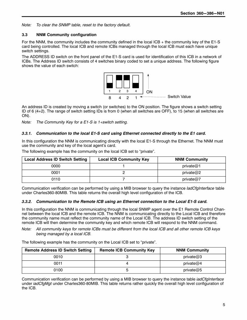
3.3 NNM Community configuration
For the NNM, the community includes the community defined in the local ICB + the community key of the E1-Scard being controlled. The local ICB and remote ICBs managed through the local ICB must each have uniqueswitch settings.The ADDRESS ID switch on the front panel of the E1-S card is used for identification of this ICB in a network ofICBs. The Address ID switch consists of 4 switches binary coded to set a unique address. The following figureshows the value of each switch:
� � � �
8 4 2 1ON
Switch Value
An address ID is created by moving a switch (or switches) to the ON position. The figure shows a switch settingID of 6 (4+2). The range of switch setting IDs is from 0 (when all switches are OFF), to 15 (when all switches areON).
Note: The Community Key for a E1-S is 1+switch setting.
3.3.1. Communication to the local E1-S card using Ethernet connected directly to the E1 card.
In this configuration the NNM is communicating directly with the local E1-S through the Ethernet. The NNM mustuse the community and key of the local agent’s card.
The following example has the community on the local ICB set to “private”.
Local Address ID Switch Setting Local ICB Community Key NNM Community
0000 1 private@1
0001 2 private@2
0110 7 private@7
Communication verification can be performed by using a MIB browser to query the instance IadCfgInterface tableunder Charles360-80MIB. This table returns the overall high level configuration of the ICB.
3.3.2. Communication to the Remote ICB using an Ethernet connection to the Local E1-S card.
In this configuration the NNM is communicating through the local SNMP agent over the E1 Remote Control Chan-nel between the local ICB and the remote ICB. The NNM is communicating directly to the Local ICB and thereforethe community name must reflect the community name of the Local ICB. The address ID switch setting of theremote ICB will then determine the community key and which remote ICB will respond to the NNM command.
Note: All community keys for remote ICBs must be different from the local ICB and all other remote ICB keysbeing managed by a local ICB.
The following example has the community on the Local ICB set to “private”.
Remote Address ID Switch Setting Remote ICB Community Key NNM Community
0010 3 private@3
0011 4 private@4
0100 5 private@5
Communication verification can be performed by using a MIB browser to query the instance table iadCfgInterfaceunder iadCfgMgt under Charles360-80MIB. This table returns rather quickly the overall high level configuration ofthe ICB.

Section 360–386–N01
�
4. TRAPS
To activate and receive ongoing status changes from a local ICB, both of the ICBs must be enabled to send infor-mation traps and the SNMP manager must be configured to recognize the transmitted traps. Before trap configu-ration can be enabled, the following 3 actions must be completed and made operational.
1. The “Trap IP Table” at the ICB must be configured through the craft interface.
2. The “Trap Proxy” must be enabled and set through the MIB.
3. The SNMP manager must be configured to recognize and display the traps.
4.1 Configuring the Trap IP Table at the ICB
This table defines the IP address of the trap recipient and identifies the community that sent the trap.Traps enabled in this table must also have the trap proxy enabled through the SNMP manager before traps willbe sent.Use the following steps to configure the Trap IP table at the ICP. A sample Trap IP Table screen is shown inFigure 4 for reference.
Step Action
1. Under “Community”, enter the name to be used to identify the location of the application traps from theICB.
2. Under “IP Address”, enter the IP Address of the machine where the traps will be sent.
3. Under “Status”, enable the trap status to generate and transmit traps from the ICB.
Figure 4. Trap IP Table
Note: To clear the SNMP table, reset to the factory default.

���������� ����
�
4.2 Configuring the Trap Proxy through the MIB
Under iadTrapMgt select iadTrapSetProxy and set the instance value = 1 to enable traps. This can be accomplished by Querying iadTrapMgt and obtaining the instance or by entering a 0 for the instanceand setting a value of 1.After setting the trap management proxy, it is suggested to do query iadTrapMgt to verify that the trap community,IP addresses and status are configured for all trap generators. If an error has occurred, no detail information willbe returned.
4.3 Configuring the Trap IP display at the NNM
Traps must be configured in the SNMP manager to be displayed.
Using HP OpenView, this is configured under Options > event configuration > ENTERPRISES SNMP Traps. Theinformation is then configured to be displayed in the desired alarm notification category.
5. CONTROLLING AND CHANGING ICB CONFIGURATIONS
A description of each function is normally available with each set and query command function. If necessary, theactual MIB source can be viewed with a text editor for more detailed information. The query command providesthe current instance configuration information while the set command provides the capability to change theinstance configuration. For additional information on individual cards refer to the card documentation.
Note: There are a number of configurations that are blocked by the Craft interface and GUI software programs.The SNMP software does not block some of these configurations and it is therefore important that theuser is trained in operation of the 360-80 system before altering card and system configurations to pre-vent unintentional changes. Viewing the unit from the front, SNMP uses the slot designations as:
Slot 1 Slot 2
Slot 0 Slot 3
The MIB is divided into 6 main categories.
5.1 iadCfgMgt
iadCfgMgt is for setting configuration of each individual channels of the cards installed in the ICB.
5.2 iadSysMgt
iadSysMgt is for setting the system time and operating mode configuration.
5.3 iadMtnMgt
iadMtnMgt is for system maintenance which includes setting/clearing loopbacks and performing channel tests andsetting test tones.
5.4 iadAlmMgt
iadAlmMgt is for viewing E1 alarm status. There are 5 alarms that can be queried.
Alarm Definition
ACTLPBKL E1 path is in local line loop back
AIS All 1s are being received on the E1 path. This is sometimes known as a Blue alarm
LOF Red alarm indicating loss of frame on the E1 path
LOS Red alarm indicating loss of signal on the E1 path
YELMN Yellow alarm indicating the far end of the E1 path is in red alarm
5.5 iadPMMgt
iadPMMgt is for viewing/clearing E1 performance monitoring counters.

Section 360–386–N01
�
5.6 iadTrapMgt
iadTrapMgt is for setting the trap proxy and viewing/configuring traps. There are 6 generated traps.
Alarm Definition
AIS All 1s are being received on the E1 path
LOF On the E1 path – Loss of Frame (red alarm)
LOS On the E1 path – Loss of Signal (red alarm)
YELMN Yellow alarm on the path (red alarm on the remote unit)
Warm Start System performed a warm start using its stored configuration
Authentication Trap A non authorized manager has attempted a query of the local SNMP agent
6. TECHNICAL ASSISTANCE
If technical assistance is required, contact Charles Industries’ Technical Services Center at:847-806-8500847-806-8556 (FAX)[email protected] (e-mail)
7. MIB OBJECT IDENTIFIER
A summary of the command set of the MIB used for control and management of th 360-80 Intelligent ChannelBank is provided here.
Each command appears in the format used to indicate the actual identifier for a managed object. To determinethe full object identifier from ‘root’:
Step Action
1. Start with the identifier string of 1.3.6.1.4.1.
2. Concatinate the Charles portion of the string 11782.1.1.1.
3. Concatinate the section number from this document.
4. For example the object ‘iadCfgInterfaceCardType’ would have an object identifier of1.3.6.1.4.1.11782.1.1.1.1.2.1.2
enterprises
11782. charles11782.1charlesIAD
11782.1.1 charles360–80
11782.1.1.1 charles360–80E1
IAD CONFIGURATION MANAGEMENT GROUP
1. iadCfgMgt
1.1 iadCfgSetSecE1ForceByPass
This command enables/disables force bypass operation of secondary E1. If the force bypass operation is execut-ed, the system will not be recoverable unless the card is powered down and then powered back up.
1: Execute force bypass operation of secondary E1.
���������� ����
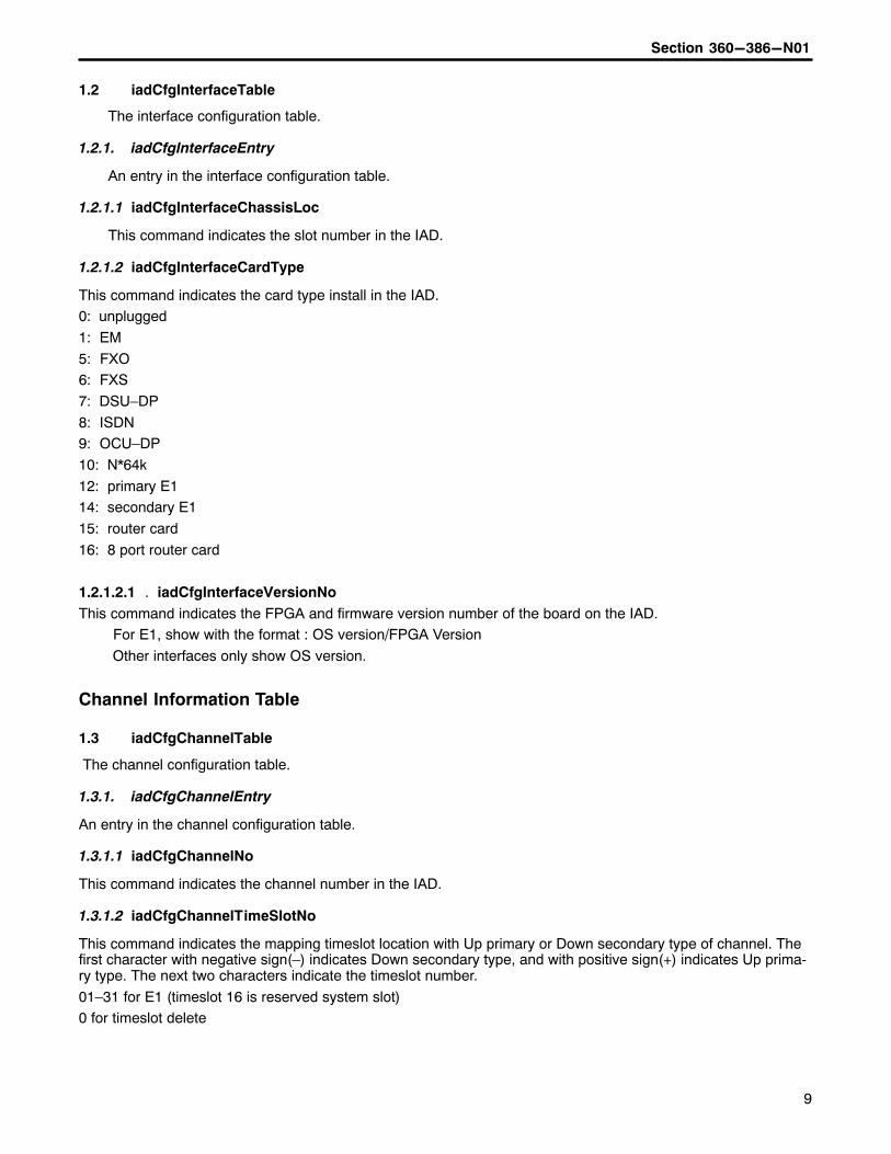
1.2 iadCfgInterfaceTable
The interface configuration table.
1.2.1. iadCfgInterfaceEntry
An entry in the interface configuration table.
1.2.1.1 iadCfgInterfaceChassisLoc
This command indicates the slot number in the IAD.
1.2.1.2 iadCfgInterfaceCardType
This command indicates the card type install in the IAD.0: unplugged
1: EM
5: FXO6: FXS
7: DSU–DP
8: ISDN9: OCU–DP
10: N*64k
12: primary E114: secondary E1
15: router card
16: 8 port router card
1.2.1.2.1 iadCfgInterfaceVersionNo.
This command indicates the FPGA and firmware version number of the board on the IAD. For E1, show with the format : OS version/FPGA Version
Other interfaces only show OS version.
Channel Information Table
1.3 iadCfgChannelTable
The channel configuration table.
1.3.1. iadCfgChannelEntry
An entry in the channel configuration table.
1.3.1.1 iadCfgChannelNo
This command indicates the channel number in the IAD.
1.3.1.2 iadCfgChannelTimeSlotNo
This command indicates the mapping timeslot location with Up primary or Down secondary type of channel. Thefirst character with negative sign(–) indicates Down secondary type, and with positive sign(+) indicates Up prima-ry type. The next two characters indicate the timeslot number.
01–31 for E1 (timeslot 16 is reserved system slot)0 for timeslot delete

Section 360–386–N01
�
E1 Configuration Table
1.4 iadCfgE1Table
The E1 configuration table.
1.4.1. iadCfgE1Entry
An entry in the E1 configuration table.
1.4.1.1 iadCfgE1CardType
This command indicates the E1 card type.
2: Primary E13: Secondary E1(Drop/Insert E1)
1.4.1.2 iadCfgE1TimeSource
This command indicates the timing supply source of primary E1 card.0: LPD (loop timing)
1: EXT (external timing source)
2: INT (internal timing source)
Note: If E1CardType is secondary E1, ignore this command.
1.4.1.3 iadCfgE1LineCode
This command indicates the line code of E1 card.
3: HDB3
1.4.1.4 iadCfgE1RmtCtrlFrameFormat
This command indicates the remote control method, frame format, and occupy timeslot of E1 card.
The first character is the number of frame format.
0: Conventional1: CRC4
The next two character are the remote control method and the occupy slot number of E1.
00: None01–31: E1 timeslot number (Timelsot 16 is reserved for system slot)
99: Using facility data link.
1.4.1.5 iadCfgE1LBOEqualization
This command indicates the LBO equalization of E1 card.
E1 LBO:
10: 120 Ohm
1.4.1.6 iadCfgE1CGAProcessMode
This command indicates the CGA process mode of primary E1 card.
0: Normal
1: CM22: CM3
Note: If E1CardType is secondary E1, ignore this command.
1.4.1.7 iadCfgE1ACO

���������� ����
��
This command allows the ACO to be activated.1: True–Activate ACO(turn off alarms)
2: False(Object will always return 2 when read)
1.4.1.8 iadCfgE1LEDStus
E1 LED status for the primary E1 card is as follows:
Bit 7–5: Reserved
Bit 4: Power LED Bit(0:OFF,1:ON)Bit 3: LOOP LED Bit(0:OFF,1:ON)
Bit 2: CGA LED Bit(0:OFF,1:ON)
Bit 1: YEL LED Bit(0:OFF,1:ON)Bit 0: RED LED Bit(0:OFF,1:ON)
E1 LED status for the secondary E1 card is as follows:
Bit 7–6: ReservedBit 5: Power LED Bit(0:OFF,1:ON)
Bit 4: LOOP LED Bit(0:OFF,1:ON)
Bit 3: CGA LED Bit(0:OFF,1:ON)Bit 2: YEL LED Bit(0:OFF,1:ON)
Bit 1: RED LED Bit(0:OFF,1:ON)
Bit 0: Add secondary E1 bypass LED Bit(0:OFF,1:ON)
FXO Configuration Table
1.5 iadCfgFXOTable
The FXO configuration table.
1.5.1. iadCfgFXOEntry
An entry in the FXO configuration table.
1.5.1.1 iadCfgFXOCardType
This command indicates the FXO card type. The values mean:0: FXO/GS
1: FXO/LS
2: DPT/NORMAL3: DPT/WINK
1.5.1.2 iadCfgFXOForceBusy
This command indicates the forced busy operation.
0: Disable (not Forced busy)1: Enable (Forced busy)
1.5.1.3 iadCfgFXOImpedance
This command indicates the impendance 600/900 ohm type of the FXO card.0: 600 ohm
1: 900 ohm
1.5.1.4 iadCfgFXOCGAMode

Section 360–386–N01
��
This command indicates the CGA mode of the FXO card.0: Immediate mode – idle, Delay mode – idle
1: Immediate mode – idle, Delay mode – busy
2: Immediate mode – busy, Delay mode – idle3: Immediate mode – busy, Delay mode – busy
1.5.1.5 iadCfgFXOTransmitLevel
This command indicates the TTLP transmit level value of the FXO card.If you want to set as 1.5dBm, input 15.
If you want –12.8dBm, input –128.
Maximum value is 6.0dBm and minimum value is –10.0dBm.
1.5.1.6 iadCfgFXOReceiveLevel
This command indicates the RTLP receive level value of the FXO card.
If you want to set as 1.5dBm, input 15.
If you want –12.8dBm, input –128.Maximum value is 6.0dBm and minimum value is –10.0dBm.
1.5.1.7 iadCfgFXOLEDStus
This command indicates the LED status of the FXO card.0: OFF
1: ON(Busy)
FXS Configuration Table
1.6 iadCfgFXSTable
The FXS configuration table.
1.6.1. iadCfgFXSEntry
An entry in the FXS configuration table.
1.6.1.1 iadCfgFXSCardType
This command indicates the FXS card type.
0: FXS/GS1: FXS/LS
2: PLARD/D3
3: PLARD/D44: MEGACOM/GS/immediate
5: MEGACOM/GS/wink
6: MEGACOM/LS7: DPO
1.6.1.2 iadCfgFXSForceBusy
This command allows the forced busy operation to be enable or disable for the FXS card.
0: Disable(not Forced busy)1: Enable(Forced busy)
1.6.1.3 iadCfgFXSImpedance

���������� ����
��
This command indicates the impendance 600/900 ohm type for the FXS card.0: 600 ohm
1: 900 ohm
1.6.1.4 iadCfgFXSCGAMode
This command indicates the CGA mode for the FXS card.
0: Immediate mode – idle, Delay mode – idle
1: Immediate mode – idle, Delay mode – busy2: Immediate mode – busy, Delay mode – idle
3: Immediate mode – busy, Delay mode – busy
1.6.1.5 iadCfgFXSTransmitLevel
This command indicates the TTLP transmit level value of FXS card.If you want to set as 1.5dBm, input 15.
If you want –12.8dBm, input –128.
Note: Maximum value is 6.0dBm and minimum value is –10.0dBm.
1.6.1.6 iadCfgFXSReceiveLevel
This command indicates the RTLP receive level of FXS card.
If you want to set as 1.5dBm, input 15.
If you want –12.8dBm, input –128.
Note: Maximum value is 1.0dBm and minimum value is –15.0dBm.
1.6.1.7 iadCfgFXSRingMode
This command indicates the ring mode of the FXS card.
0: Interrupted1: Burst
2: Continuous
1.6.1.8 iadCfgFXSLEDStus
This command indicates the LED status of the FXS card.
0: OFF
1: ON(Busy)
E&M Configuration Table
1.7 iadCfgEMTable
The E&M configuration table.
1.7.1. iadCfgEMEntry
An entry in the E&M configuration table.
1.7.1.1 iadCfgEMCardType
This command indicates the E&M card type.1: type I
2: type II
Section 360–386–N01
��
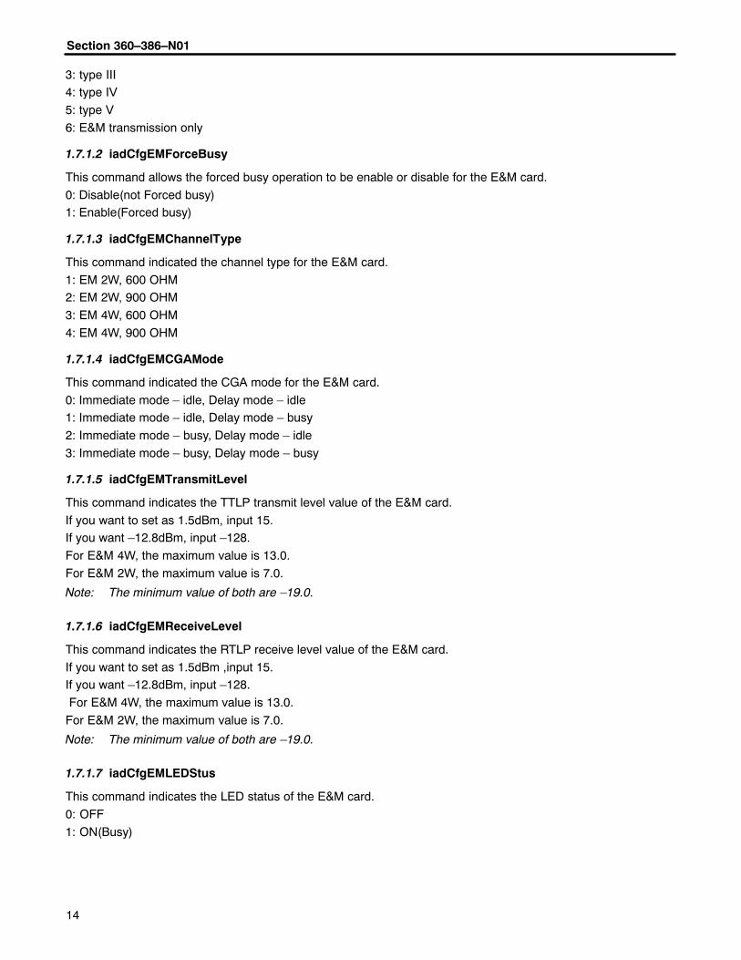
3: type III4: type IV
5: type V
6: E&M transmission only
1.7.1.2 iadCfgEMForceBusy
This command allows the forced busy operation to be enable or disable for the E&M card.
0: Disable(not Forced busy)1: Enable(Forced busy)
1.7.1.3 iadCfgEMChannelType
This command indicated the channel type for the E&M card.
1: EM 2W, 600 OHM2: EM 2W, 900 OHM
3: EM 4W, 600 OHM
4: EM 4W, 900 OHM
1.7.1.4 iadCfgEMCGAMode
This command indicated the CGA mode for the E&M card.
0: Immediate mode – idle, Delay mode – idle1: Immediate mode – idle, Delay mode – busy
2: Immediate mode – busy, Delay mode – idle
3: Immediate mode – busy, Delay mode – busy
1.7.1.5 iadCfgEMTransmitLevel
This command indicates the TTLP transmit level value of the E&M card.
If you want to set as 1.5dBm, input 15.If you want –12.8dBm, input –128.
For E&M 4W, the maximum value is 13.0.
For E&M 2W, the maximum value is 7.0.
Note: The minimum value of both are –19.0.
1.7.1.6 iadCfgEMReceiveLevel
This command indicates the RTLP receive level value of the E&M card.
If you want to set as 1.5dBm ,input 15.If you want –12.8dBm, input –128.
For E&M 4W, the maximum value is 13.0.
For E&M 2W, the maximum value is 7.0.
Note: The minimum value of both are –19.0.
1.7.1.7 iadCfgEMLEDStus
This command indicates the LED status of the E&M card.
0: OFF
1: ON(Busy)

���������� ����
��
DSU-DP Configuration Table
1.8 iadCfgDSUDPTable
The DSU-DP configuration table.
1.8.1. iadCfgDSUDPEntry
An entry in the DSU-DP configuration table.INDEX { iadCfgChannelNo }
1.8.1.1 iadCfgDSUDPLatchLpBk
This command allows the operation of latch loopback to be enabled or disabled for the DSU-DP card.0: Disable
1: Enable
1.8.1.2 iadCfgDSUDPRTSforce
This command allows the RTS force operation to be enabled or disabled for the OCU-DP card.
0: Disable
1: Enable
1.8.1.3 iadCfgDSUDPBCHErrCorrect
This command allows the BCH error correction operation to be enabled or disabled for the DSU-DP card.
0: Disable
1: Enable
1.8.1.4 iadCfgDSUDPSyncMode
This command allows the sync mode to be set for the OCU-DP card.
0: Asynchronous1: Synchronous
1.8.1.5 iadCfgDSUDPBitMode
This command allows the bit mode selection to be set for the OCU-DP card.
0: 7 bits mode1: 8 bits mode
1.8.1.6 iadCfgDSUDPZCS
This command allows the Zero Code Suppression operation to be enabled or disabled for the DSU-DP card.0: Disable
1: Enable
1.8.1.7 iadCfgDSUDPDataRate
This command indicates the data rate to be set for the DSU-DP card.
0: 2.4 kbps
1: 4.8 kbps2: 9.6 kbps
3: 19.2 kbps
4: 56 kbps (Sync only)5: 64 kbps (Sync only)

Section 360–386–N01
��
1.8.1.8 iadCfgDSUDPStopBitShorten
This command allows the stop bit shorten to be set for the DSU-DP card.
0: 12.5%
1: 25%
1.8.1.9 iadCfgDSUDPStopBit
This command allows the stop bit selection to be set for the DSU-DP card.
0: 1 stop bit
1: 2 stop bits
1.8.1.10 iadCfgDSUDPParityBit
This command allows the parity bit selection to be set for the DSU-DP card.
0: no parity1: parity
1.8.1.11 iadCfgDSUDPIFMode
This command allows the interface mode selection to be set for the DSU-DP card.
2: RS5303: v.36/RS449
4: V.356: RS232
1.8.1.12 iadCfgDSUDPCTSCtrl
This command allows the CTS control to be set for the DSU-DP card.
0: disable1: enable, CTS value = 0
2: enable, CTS value = 1
1.8.1.13 iadCfgDSUDPDSRCtrl
This command allows the DSR control to be set for the DSU-DP card.
0: disable
1: enable, CTS value = 02: enable, CTS value = 1
1.8.1.14 iadCfgDSUDPDCDCtrl
This command allows the DCD control to be set for the DSU-DP card.
0: disable1: enable, CTS value = 0
2: enable, CTS value = 1
OCU-DP Configuration Table
1.9 iadCfgOCUDPTable
The OCU-DP configuration table.
1.9.1. iadCfgOCUDPEntry
An entry in the OCU-DP configuration table.

���������� ����
��
1.9.1.1 iadCfgOCUDPSelection
This command indicates the selection of CSU or DSU for the OCU-DP card.
0: CSU
1: DSU
1.9.1.2 iadCfgOCUDPCMICode
This command allows the alternating CMI code operation to be enabled or disabled for the OCU-DP card.
0: Disable
1: Enable
1.9.1.3 iadCfgOCUDPBCHErrCorrect
This command allows the BCH error correction operation to be enabled or disabled for the OCU-DP card.
0: Disable1: Enable
1.9.1.4 iadCfgOCUDPZCS
This command allows the Zero Code Suppression operation to be enabled or disabled for the OCU-DP card.
0: Disable1: Enable
1.9.1.5 iadCfgOCUDPSubrate
This command allows the speed of the subrate channel to be set for the OCU-DP card.0: 2.4 kbps
1: 4.8 kbps
2: 9.6 kbps3: 19.2 kbps
4: 56 kbps
5: 64 kbps6: SW 56 kbps
1.9.1.6 iadCfgOCUDPLatchLpBk
This command allows the operation of latch loopback to be enabled or disabled for the OCU-DP card.0: Disable
1: Enable
1.9.1.7 iadCfgOCUDPLEDStus
This command indicates the LED status of the OCU-DP card.0: OFF
1: ON (Busy)
ISDN Configuration Table
1.10 iadCfgISDNTable
The ISDN configuration table.
1.10.1. iadCfgISDNEntry
An entry in the ISDN configuration table.

Section 360–386–N01
��
1.10.1.1 iadCfgISDNServiceMode
This command indicates the service mode for the ISDN card.
0: D
1: 1B+D2: 2B+D
1.10.1.2 iadCfgISDNSealingCurrent
This command allows the sealing current to be enabled or disabled for the ISDN card.
0: Disable1: Enable
1.10.1.3 iadCfgISDNLTNTMode
This command indicates whether the ISDN card is in LULT or LUNT mode.0: LULT
1: LUNT
1.10.1.4 iadCfgISDNLEDStus
This command indicates the LED status of the ISDN card.Byte 2: Loss Of Sync status with Red(0:OFF,1:ON)
Byte 1: Alarm Status with Yellow(0:OFF,1:ON)Byte 0: Loopback Status with Green(0:OFF,1:ON)
Nx64k Configuration Table
1.11 iadCfgNx64kTable
The Nx64k configuration table.
1.11.1. iadCfgNx64kEntry
An entry in the Nx64k configuration table.
1.11.1.1 iadCfgNx64kChannelType
This command allows the interface mode selection to be set for the Nx64k card.2: RS–530
4: v.35
5: v.36 6: RS–232
1.11.1.2 iadCfgNx64kMultiChMode
This command indicates the multi–channel mode of the Nx64k card.1: N=1, 1*64k
2: N=2, 2*64k
30: N=30, 30*64k(maximum for E1)
1.11.1.3 iadCfgNx64kExtClock
This command allows the external clock to be enabled or disabled for the Nx64k card.
0: Disable1: Enable

���������� ����
�
1.11.1.4 iadCfgNx64kRate
This command indicates the rate of Nx64k card.
0: 56k
1: 64k
1.11.1.5 iadCfgNx64kDTELL
This command indicates the operation of DTE LL to be enabled or disabled for the Nx64k card.
0: Disable
1: Enable
1.11.1.6 iadCfgNx64kV54LPBK
This command allows the operation of the v.54 Loopback to be enabled or disabled for the Nx64k card.
0: Disable1: Enable
1.11.1.7 iadCfgNx64kPRTS
This command alloes the operation of PRTS to be enabled or disabled for the Nx64k card.
0: Disable1: Enable
1.11.1.8 iadCfgNx64kCTSCtrl
This command allows the CTS control to be set for the Nx64k card.0: Disable
1: Enable, CTS value = 0
2: Enable, CTS value = 1
1.11.1.9 iadCfgNx64kDSRCtrl
This command allows the DSR control to be set for the Nx64k card.
0: Disable1: Enable, CTS value = 0
2: Enable, CTS value = 1
1.11.1.10 iadCfgNx64kDCDCtrl
This command allows the DCD control to be set for the Nx64k card.0: Disable
1: Enable, CTS value = 0
2: Enable, CTS value = 1
1.11.1.11 iadCfgNx64kZCS
This command allows the Zero Code Suppression operation to be enabled or disabled for the Nx64k card.
0: Disable1: Enable
1.11.1.12 iadCfgNx64kIdleMode
This command allows the idle mode to be set for the Nx64k card.0: With idle mode 11111110
1: With idle mode 11111111
Section 360–386–N01
�
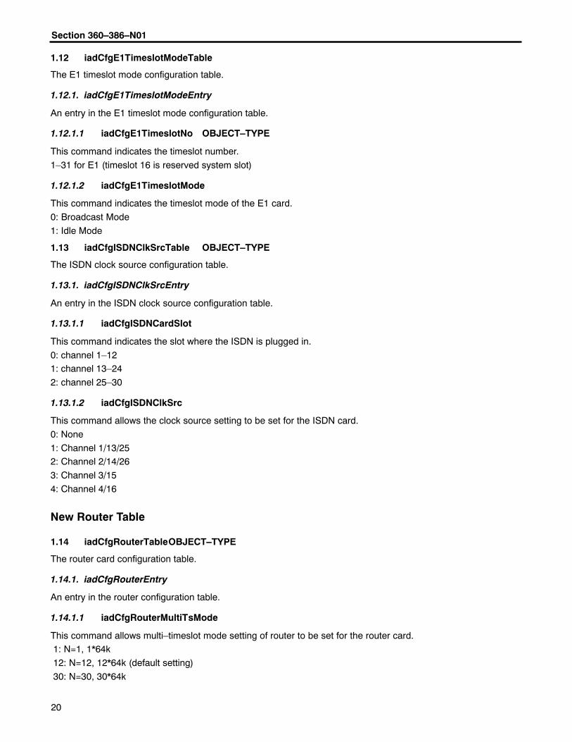
1.12 iadCfgE1TimeslotModeTable
The E1 timeslot mode configuration table.
1.12.1. iadCfgE1TimeslotModeEntry
An entry in the E1 timeslot mode configuration table.
1.12.1.1 iadCfgE1TimeslotNo OBJECT–TYPE
This command indicates the timeslot number.
1–31 for E1 (timeslot 16 is reserved system slot)
1.12.1.2 iadCfgE1TimeslotMode
This command indicates the timeslot mode of the E1 card.
0: Broadcast Mode
1: Idle Mode
1.13 iadCfgISDNClkSrcTable OBJECT–TYPE
The ISDN clock source configuration table.
1.13.1. iadCfgISDNClkSrcEntry
An entry in the ISDN clock source configuration table.
1.13.1.1 iadCfgISDNCardSlot
This command indicates the slot where the ISDN is plugged in.
0: channel 1–121: channel 13–24
2: channel 25–30
1.13.1.2 iadCfgISDNClkSrc
This command allows the clock source setting to be set for the ISDN card.
0: None
1: Channel 1/13/252: Channel 2/14/26
3: Channel 3/15
4: Channel 4/16
New Router Table
1.14 iadCfgRouterTableOBJECT–TYPE
The router card configuration table.
1.14.1. iadCfgRouterEntry
An entry in the router configuration table.
1.14.1.1 iadCfgRouterMultiTsMode
This command allows multi–timeslot mode setting of router to be set for the router card. 1: N=1, 1*64k
12: N=12, 12*64k (default setting)
30: N=30, 30*64k
���������� ����
��
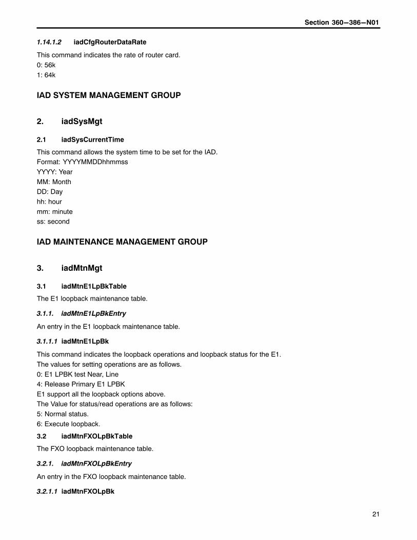
1.14.1.2 iadCfgRouterDataRate
This command indicates the rate of router card.
0: 56k
1: 64k
IAD SYSTEM MANAGEMENT GROUP
2. iadSysMgt
2.1 iadSysCurrentTime
This command allows the system time to be set for the IAD.Format: YYYYMMDDhhmmss
YYYY: Year
MM: MonthDD: Day
hh: hour
mm: minutess: second
IAD MAINTENANCE MANAGEMENT GROUP
3. iadMtnMgt
3.1 iadMtnE1LpBkTable
The E1 loopback maintenance table.
3.1.1. iadMtnE1LpBkEntry
An entry in the E1 loopback maintenance table.
3.1.1.1 iadMtnE1LpBk
This command indicates the loopback operations and loopback status for the E1.
The values for setting operations are as follows.
0: E1 LPBK test Near, Line4: Release Primary E1 LPBK
E1 support all the loopback options above.The Value for status/read operations are as follows:
5: Normal status.
6: Execute loopback.
3.2 iadMtnFXOLpBkTable
The FXO loopback maintenance table.
3.2.1. iadMtnFXOLpBkEntry
An entry in the FXO loopback maintenance table.
3.2.1.1 iadMtnFXOLpBk
Section 360–386–N01
��
This command indicates loopback operations and loopback status for the FXO card.0: Release
1: Loopback
3.2.1.2 iadMtnFXO1kTestTone
This command indicates the operations of the tone test for the FXO card.
There are 3 types 1k tone test status for the FXO card:
0: Release 1k test tone.1: 1k test tone with XMT direction
2: 1k test tone with RCV direction
3.2.1.3 iadMtnFXOToneTest
This command allows the operation of tone test and tone test status for the FXO card.The values for setting operations are as follows:
1: Operate tone test
The values for status/read operations are as follows:2: Success
3: Fail
4: Without doing tone test.
3.3 iadMtnFXSLpBkTable
The FXS loopback maintenance table.
3.3.1. iadMtnFXSLpBkEntry
An entry in the FXS loopback maintenance table.
3.3.1.1 iadMtnFXSLpBk
This command indicates loopback operations and loopback status for the FXS card.0: Release
1: Loopback
3.3.1.2 iadMtnFXS1kTestTone
This command indicates the operations of tone test for the FXS card.There are 3 types 1k tone test status of FXS card:
0: Release 1k test tone.
1: 1k test tone with XMT direction2: 1k test tone with RCV direction
3.3.1.3 iadMtnFXSToneTest
This command allows the operation of tone test and tone test status for the FXS card.The values for setting operations are as follows:
1: Operate tone test
The values for status/read operations are as follows:2: Success
3: Fail
4: Without doing tone test.
���������� ����
��
E&M Loopback Maintenance Table
3.4 iadMtnEMLpBkTable
The E&M loopback maintenance table.
3.4.1. iadMtnEMLpBkEntry
An entry in the E&M loopback maintenance table.
3.4.1.1 iadMtnEMLpBk
This command indicates loopback operations and loopback status for the E&M card.
0: Release1: Loopback
3.4.1.2 iadMtnEM1kTestTone
This command indicates the operations of the tone test for the E&M card.There are 3 types 1k tone test status for the E&M card:
0: Release 1k test tone.
1: 1k test tone with XMT direction2: 1k test tone with RCV direction
3.4.1.3 iadMtnEMToneTest
This command allows the operation of tone test and tone test status for the E&M card.
The values for setting operations are as follows:1: Operate tone test.
The values for status/read operations are as follows:
2: Success3: Fail
4: Without doing tone test
ISDN Loopback Test Maintenance Table
3.5 iadMtnISDNLpBkTable
The ISDN loopback maintenance table.
3.5.1. iadMtnISDNLpBkEntry
An entry in the ISDN loopback maintenance table.
3.5.1.1 iadMtnISDNLpBk
This command indicates loopback operations and loopback status for the ISDN card.
The values for setting operations are as follows:0: Release Loopback
1: Local Loopback
2: LULT Loopback3: NNT1 Loopback
The values for status/read operations are as follows:
4: Normal5: Loopback

Section 360–386–N01
��
Nx64k Loopback Test Maintenance Table
3.6 1.1iadMtnNx64kLpBkTable
The Nx64k loopback maintenance table.
3.6.1. iadMtnNx64kLpBkEntry
An entry in the Nx64k loopback maintenance table.
3.6.1.1 iadMtnNx64kLpBk
This command indicates operations and report status for the Nx64k card.
The values for setting operations are as follows:0: Local Loopback
1: network Loopback
2: Remote Loopback3: Release Loopback
4: Normal
5: Local Loopback6: Local Loopback by DTE
7: Remote Loopback
8: Network Loopback9: Network Loopback by Remote.
IAD ALARM MANAGEMENT GROUP
4. iadAlmMgt
4.1 iadAlmTable
The alarm table.
4.1.1. iadAlmEntry
An entry in the alarm table.
4.1.1.1 iadAlmType
The alarm types for E1 card.
0: ACTLPBKL alarm
3: AIS alarm4: LOF alarm
5: LOS alarm6: YEL alarm
4.1.1.2 iadAlmStus
This command allows the alarm status to be read.
0: Alarm has not occurred1: Alarm has occurred

���������� ����
��
IAD PERFORMANCE MONITOR MANAGEMENT GROUP
5. iadPMMgt
5.1 iadPMResetTable
The Performance Monitoring reset table.
5.1.1. iadPMResetEntry
An entry in the Performance Monitoring reset table.
5.1.1.1 iadPMResetType
This command allows the Performance Monitoring (PM) to be reset for the specified card.0: Reset 15-minute PM values
1: Reset 1-day PM values
Reading this command will always return 2.
5.2 iadPMPriE115PMTable
The Performance Monitoring table for the 15-minute PM of the primary E1 card.
5.2.1. iadPMPriE115PMEntry
An entry in the Performance Monitoring table for the 15-minute PM of the primary E1 card.
5.2.1.1 iadPMType
The PM types:
0: Error Second1: Severely Error Second
2: Failed second
5.2.1.2 iadPM15IntervalNo
A number between 0 and 96, which identifies the interval for which the set of statistics is available. The intervalidentified by 1 is the most recently completed 15 minute interval, and the interval identified by N is the intervalimmediately preceding the one identified by N-1. 0 for current 15 minute interval.
5.2.1.3 iadPMPriE115PMValue
The 15-minute PM value of primary E1 card.
5.3 iadPMPriE124PMTable
The Performance Monitoring table for the 1-day PM of the primary E1 card.
5.3.1. iadPMPriE124PMEntry
An entry in the Performance Monitoring table for the 1-day PM of the primary E1 card.
5.3.1.1 iadPM24IntervalNo
A number between 0 and 30, which identifies the interval for which the set of statistics is available. The intervalidentified by 1 is the most recently completed 24 hours interval, and the interval identified by N is the interval im-mediately preceding the one identified by N-1. 0 for today.
5.3.1.2 iadPMPriE124PMValue
The 1-day PM value of primary E1 card.
Section 360–386–N01
��
5.4 iadPMSecE115PMTable
The Performance Monitoring table for the 15-minute PM of the secondary E1 card.
5.4.1. iadPMSecE115PMEntry
An entry in the Performance Monitoring table for the 15-minute PM of the secondary E1 card.
5.4.1.1 iadPMSecE115PMValue
The 15-minute PM value of secondary E1 card
5.5 iadPMSecE124PMTable
The Performance Monitoring table for the 1-day PM of secondary E1 card.
5.5.1. iadPMSecE124PMEntry
An entry in the Performance Monitoring table for the 1-day PM of the secondary E1 card.
5.5.1.1 iadPMSecE124PMValue
The 1-day PM value of secondary E1 card
IAD TRAP MANAGEMENT GROUP
6. iadTrapMgt
6.1 iadTrapSetProxy
This command indicates the trap proxy operation
0: Disable
1: Enable
6.2 iadTrapNEid
This command describes the system id that generates the trap.
6.3 iadTrapStus
This command describes the trap status:
0: Not present
1: Present
6.4 iadTrapReqIP
This command indicates the offending IP address that cause the authority failure.
Manager Host table for receiving trap alarm information
6.5 iadTrapConfigTable
The trap configuration information table.
6.5.1. iadTrapConfigEntry
An entry in the trap configuration information table.
6.5.1.1 iadTrapConfigNo
This command indicates the index of the trap configuration information table.
6.5.1.2 iadTrapConfigCommunity
���������� ����
��
This command indicates the community of the trap configuration information table.
6.5.1.3 iadTrapConfigIP
This command indicates the destination IP address of the trap configuration information table.
6.5.1.4 iadTrapConfigRowStatus
The status column used for creating, modifying, and deleting instances of the columnar objects in the trap config-uration information table.
Trap Definition
6.6 iadTrapObject
Trap object.
� � �