Embed Size (px)
Citation preview
TALAT Lecture 3705
Drawing of Automotive Sheet Metal Parts
30 pages, 37 figures
Advanced Level
prepared by Klaus Siegert, Institut für Umformtechnik, Universität Stuttgart Objectives: − to describe the special requirements for the successful fabrication of automotive alu-
minium sheet metal parts with respect to material properties, machinery and drawing equipment and tools
Prerequisites: − General production engineering background − Background in sheet metal forming principles − TALAT Lectures 3701 - 3704 Date of Issue: 1996 © EAA – European Aluminium Association
TALAT 3705 2
3705 Drawing of Automotive Sheet Metal Parts
Table of Contents 3705 Drawing of Automotive Sheet Metal Parts.............................................2
3705.01 Introduction................................................................................................ 3 3705.02 Characteristic Materials Parameters ....................................................... 4
Effect of Paint Bake Cycle on Strength ...................................................................4 Anisotropy................................................................................................................4
3705.03 The Drawing Process ................................................................................. 6 Stretch Forming .......................................................................................................6 Stretch Forming a Bulge with a Spherical Punch ....................................................7 Hydraulic Stretch Forming.......................................................................................8 Deep Drawing with a Hemispherical Punch ..........................................................10 Deep Drawing and Stretch Forming ......................................................................11 Drawing Irregular Sheet Shapes of Large Areas....................................................12
3705.04 Possibilities of Controlling the Material Flow....................................... 13 Control of Material Flow under Blankholder ........................................................13 Arrangement of Draw Beads..................................................................................15
3705.05 Adjusting the Die Cushion ....................................................................... 15 Mechanical vs. Hydraulic Press Equipment ..........................................................15 Four-Point Die Cushion .........................................................................................16 Desired and Actual Curves for Blankholder Force ................................................17 Advantages of a Servo-Hydraulic Die Cushion in the Press Table .......................17 Four-Point Die Cushion in the Press Table............................................................18 Four-Point Die Cushion in the Press Table with Adjustable Spindle Sleeves.......19 Functional Principle of a Spindle Sleeve Adjustment ...........................................20 Experimental Construction of a Single Action Hydraulic Press (10-Point) ..........20 Blankholder and Spindle Sleeve Forces.................................................................21 Force Displacement Curves ...................................................................................21 Demonstration Case of the Multi-Point Drawing Arrangement ............................24
3705.06 Tool Materials for Drawing of Aluminium Sheet Metal Parts ............ 25 Tool Materials........................................................................................................25 Surface Coatings for Drawing Tools .....................................................................26
3705.07 Examples................................................................................................... 27 3705.08 List of Figures............................................................................................ 29
TALAT 3705 3
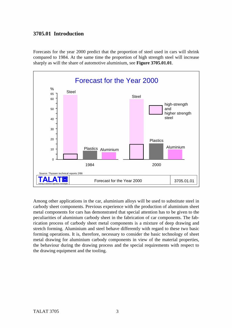
3705.01 Introduction Forecasts for the year 2000 predict that the proportion of steel used in cars will shrink compared to 1984. At the same time the proportion of high strength steel will increase sharply as will the share of automotive aluminium, see Figure 3705.01.01.
Training in Aluminium Application Technologies
alu Forecast for the Year 2000 3705.01.01
Forecast for the Year 2000
high-strengthandhigher strengthsteel
Source: Thyssen technical reports 2/86
65
60
50
40
30
20
10
0
Steel
Plastics Aluminium
Steel
PlasticsAluminium
1984 2000
%
Among other applications in the car, aluminium alloys will be used to substitute steel in carbody sheet components. Previous experience with the production of aluminium sheet metal components for cars has demonstrated that special attention has to be given to the peculiarities of aluminium carbody sheet in the fabrication of car components. The fab-rication process of carbody sheet metal components is a mixture of deep drawing and stretch forming. Aluminium and steel behave differently with regard to these two basic forming operations. It is, therefore, necessary to consider the basic technology of sheet metal drawing for aluminium carbody components in view of the material properties, the behaviour during the drawing process and the special requirements with respect to the drawing equipment and the tooling.
TALAT 3705 4
3705.02 Characteristic Materials Parameters
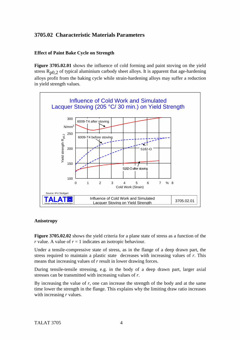
Effect of Paint Bake Cycle on Strength Figure 3705.02.01 shows the influence of cold forming and paint stoving on the yield stress Rp0,2 of typical aluminium carbody sheet alloys. It is apparent that age-hardening alloys profit from the baking cycle while strain-hardening alloys may suffer a reduction in yield strength values.
Training in Aluminium Application Technologies
alu Influence of Cold Work and SimulatedLacquer Stoving on Yield Strength 3705.02.01
Influence of Cold Work and SimulatedLacquer Stoving (205 °C/ 30 min.) on Yield Strength
Source: IFU Stuttgart
300
250
200
150
100
N/mm2
0 1 2 3 4 5 6 7 % 8Cold Work (Strain)
Yiel
d st
reng
th R
p0,2
6009-T4 after stoving
6009-T4 before stoving
5182-O
5182-O after stoving
Anisotropy
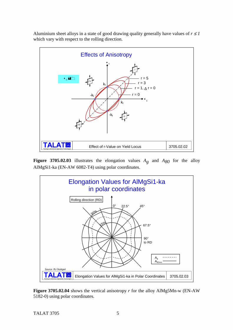
Figure 3705.02.02 shows the yield criteria for a plane state of stress as a function of the r value. A value of r = 1 indicates an isotropic behaviour.
Under a tensile-compressive state of stress, as in the flange of a deep drawn part, the stress required to maintain a plastic state decreases with increasing values of r. This means that increasing values of r result in lower drawing forces.
During tensile-tensile stressing, e.g. in the body of a deep drawn part, larger axial stresses can be transmitted with increasing values of r.
By increasing the value of r, one can increase the strength of the body and at the same time lower the strength in the flange. This explains why the limiting draw ratio increases with increasing r values.
TALAT 3705 5
Aluminium sheet alloys in a state of good drawing quality generally have values of r ≤ 1 which vary with respect to the rolling direction.
alu
Training in Aluminium Application Technologies
! "
! 1
r = 3r = 1, ∆ r = 0
r = 0
Effects of Anisotropy
Effect of r-Value on Yield Locus 3705.02.02
I
II
III
IVr = 5! # % &
kf
-kf
-kf
kf
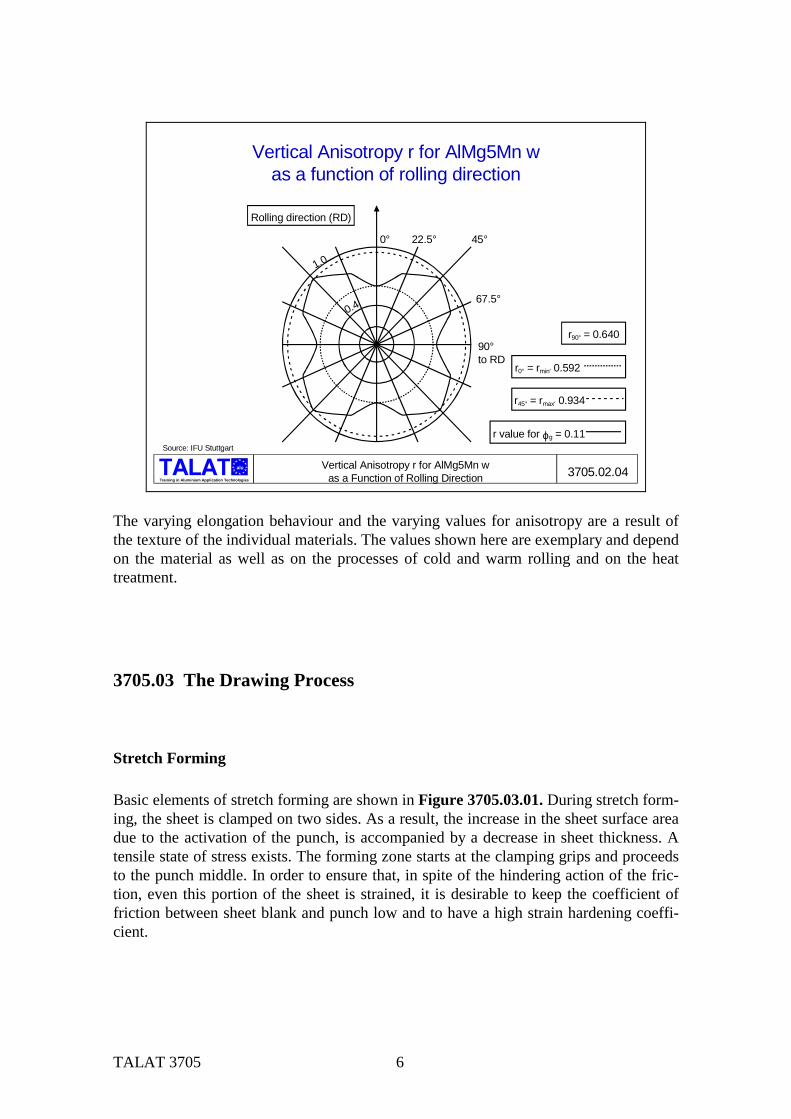
Figure 3705.02.03 illustrates the elongation values Ag and A80 for the alloy AlMgSi1-ka (EN-AW 6082-T4) using polar coordinates.
alu
Training in Aluminium Application TechnologiesElongation Values for AlMgSi1-ka in Polar Coordinates 3705.02.03
Elongation Values for AlMgSi1-kain polar coordinates
30%
0° 22.5° 45°
67.5°
90°to RD
15%
Source: IfU Stuttgart
Rolling direction (RD)
AgA80mm
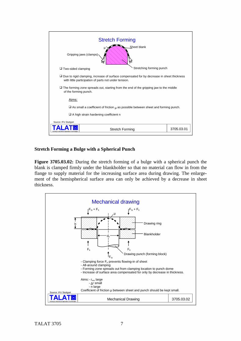
Figure 3705.02.04 shows the vertical anisotropy r for the alloy AlMg5Mn-w (EN-AW 5182-0) using polar coordinates.
TALAT 3705 6
alu
Training in Aluminium Application Technologies
Vertical Anisotropy r for AlMg5Mn w as a Function of Rolling Direction 3705.02.04
Vertical Anisotropy r for AlMg5Mn was a function of rolling direction
Source: IFU Stuttgart
1.0
0° 22.5° 45°
67.5°
90° to RD
Rolling direction (RD)
0.4
r90° = 0.640
r value for ϕg = 0.11
r0° = rmin' 0.592
r45° = rmax' 0.934
The varying elongation behaviour and the varying values for anisotropy are a result of the texture of the individual materials. The values shown here are exemplary and depend on the material as well as on the processes of cold and warm rolling and on the heat treatment.
3705.03 The Drawing Process
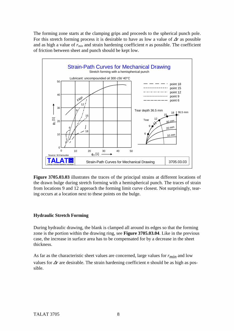
Stretch Forming Basic elements of stretch forming are shown in Figure 3705.03.01. During stretch form-ing, the sheet is clamped on two sides. As a result, the increase in the sheet surface area due to the activation of the punch, is accompanied by a decrease in sheet thickness. A tensile state of stress exists. The forming zone starts at the clamping grips and proceeds to the punch middle. In order to ensure that, in spite of the hindering action of the fric-tion, even this portion of the sheet is strained, it is desirable to keep the coefficient of friction between sheet blank and punch low and to have a high strain hardening coeffi-cient.
TALAT 3705 7
Training in Aluminium Application Technologies
alu Stretch Forming 3705.03.01
Stretch Forming
' Two-sided clamping
' Due to rigid clamping, increase of surface compensated for by decrease in sheet thickness with little participation of parts not under tension.
' The forming zone spreads out, starting from the end of the gripping jaw to the middle of the forming punch.
Aims:
' As small a coefficient of friction µ as possible between sheet and forming punch.
' A high strain hardening coefficient n
Source: IFU Stuttgart
Sheet blank
Gripping jaws (clamps)
Stretching forming punch
µ
Stretch Forming a Bulge with a Spherical Punch Figure 3705.03.02: During the stretch forming of a bulge with a spherical punch the blank is clamped firmly under the blankholder so that no material can flow in from the flange to supply material for the increasing surface area during drawing. The enlarge-ment of the hemispherical surface area can only be achieved by a decrease in sheet thickness.
alu
Training in Aluminium Application TechnologiesMechanical Drawing 3705.03.02
Mechanical drawing
Source: IFU Stuttgart
- Clamping force FK prevents flowing-in of sheet- All-around clamping- Forming zone spreads out from clamping location to punch dome- Increase of surface area compensated for only by decrease in thickness.
Aims: - rmin large - ∆r small - n largeCoefficient of friction µ between sheet and punch should be kept small.
FK
FSt
FSt + FK
µFSt + FK
FK
h
d0
Drawing ring
Blankholder
Drawing punch (forming block)
TALAT 3705 8
The forming zone starts at the clamping grips and proceeds to the spherical punch pole. For this stretch forming process it is desirable to have as low a value of ∆r as possible and as high a value of rmin and strain hardening coefficient n as possible. The coefficient of friction between sheet and punch should be kept low.
Training in Aluminium Application Technologies
alu Strain-Path Curves for Mechanical Drawing 3705.03.03
Strain-Path Curves for Mechanical Drawing
point 18point 15point 12point 9point 6
Tear
36.5 mmTear depth 36.5 mm
6
9
1215
18
30 mm
10 mm
20 mm
F
RP
Lubricant: uncompounded oil 300 cSt/ 40°C50
40
30
20
10
010 20 30 40 500
ϕ2 [1]
ϕ 1 [1
]
18
15
12
9
6
Stretch forming with a hemispherical punch
Source: W.Karsunke
Figure 3705.03.03 illustrates the traces of the principal strains at different locations of the drawn bulge during stretch forming with a hemispherical punch. The traces of strain from locations 9 and 12 approach the forming limit curve closest. Not surprisingly, tear-ing occurs at a location next to these points on the bulge.
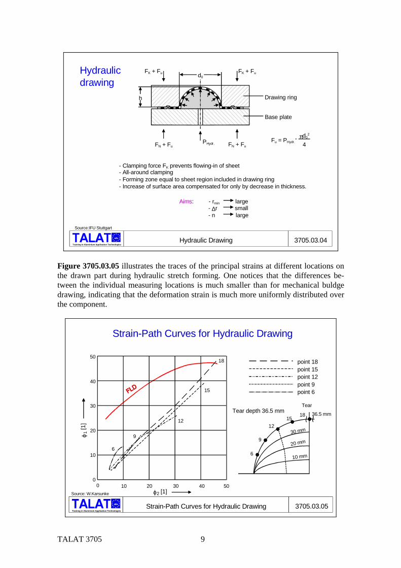
Hydraulic Stretch Forming During hydraulic drawing, the blank is clamped all around its edges so that the forming zone is the portion within the drawing ring, see Figure 3705.03.04. Like in the previous case, the increase in surface area has to be compensated for by a decrease in the sheet thickness. As far as the characteristic sheet values are concerned, large values for rmin and low values for ∆r are desirable. The strain hardening coefficient n should be as high as pos-sible.
TALAT 3705 9
alu
Training in Aluminium Application TechnologiesHydraulic Drawing 3705.03.04
Hydraulic drawing
Source:IFU Stuttgart
FN + FuPHydr.
FK + Fu FK + Fu
FN + Fu
h Drawing ring
d0
Base plate
Fu = PHydr.πd0
2
4
- Clamping force FK prevents flowing-in of sheet- All-around clamping- Forming zone equal to sheet region included in drawing ring- Increase of surface area compensated for only by decrease in thickness.
Aims: - rmin large - ∆r small - n large
Figure 3705.03.05 illustrates the traces of the principal strains at different locations on the drawn part during hydraulic stretch forming. One notices that the differences be-tween the individual measuring locations is much smaller than for mechanical buldge drawing, indicating that the deformation strain is much more uniformly distributed over the component.
Training in Aluminium Application Technologies
alu Strain-Path Curves for Hydraulic Drawing 3705.03.05
Strain-Path Curves for Hydraulic Drawing
point 18point 15point 12point 9point 6
Tear
36.5 mmTear depth 36.5 mm
6
9
1215
18
30 mm
10 mm
20 mm
50
40
30
20
10
010 20 30 40 500
ϕ2 [1]
ϕ 1 [1
]
18
15
12
9
6
Source: W.Karsunke
TALAT 3705 10
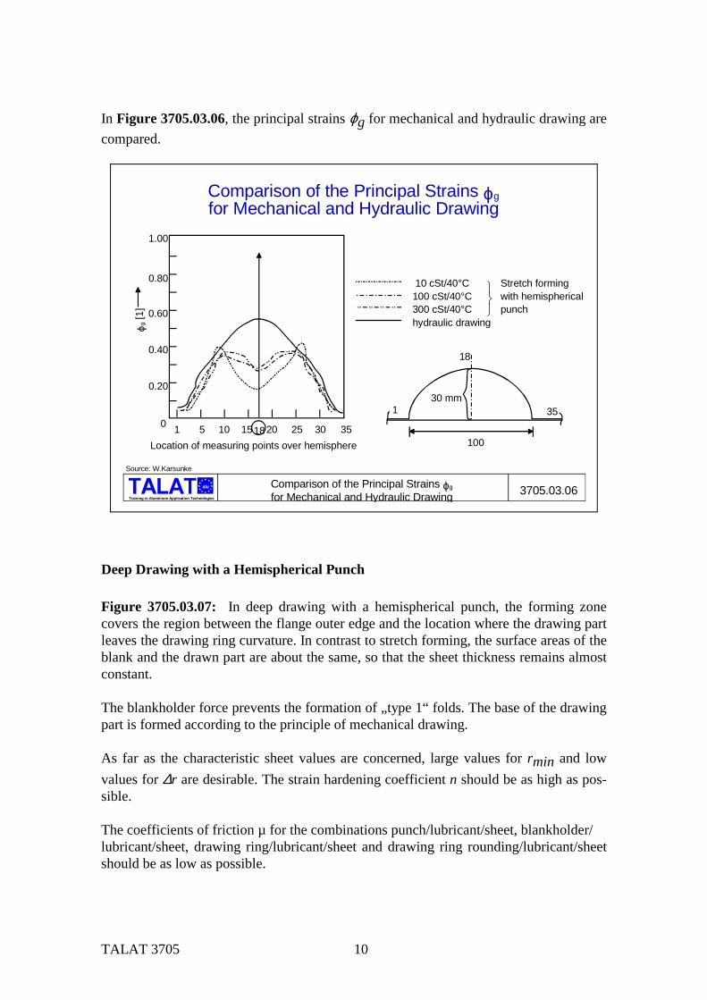
In Figure 3705.03.06, the principal strains ϕg for mechanical and hydraulic drawing are compared.
Training in Aluminium Application Technologies
alu Comparison of the Principal Strains ϕg
for Mechanical and Hydraulic Drawing 3705.03.06
Source: W.Karsunke
Comparison of the Principal Strains ϕgfor Mechanical and Hydraulic Drawing
10 cSt/40°C100 cSt/40°C300 cSt/40°Chydraulic drawing
Stretch formingwith hemisphericalpunch
18
30 mm351
100
1.00
0.80
1 5 10 15 20 25 30 3518Location of measuring points over hemisphere
0.60
0.40
0.20
0
ϕg [1
]
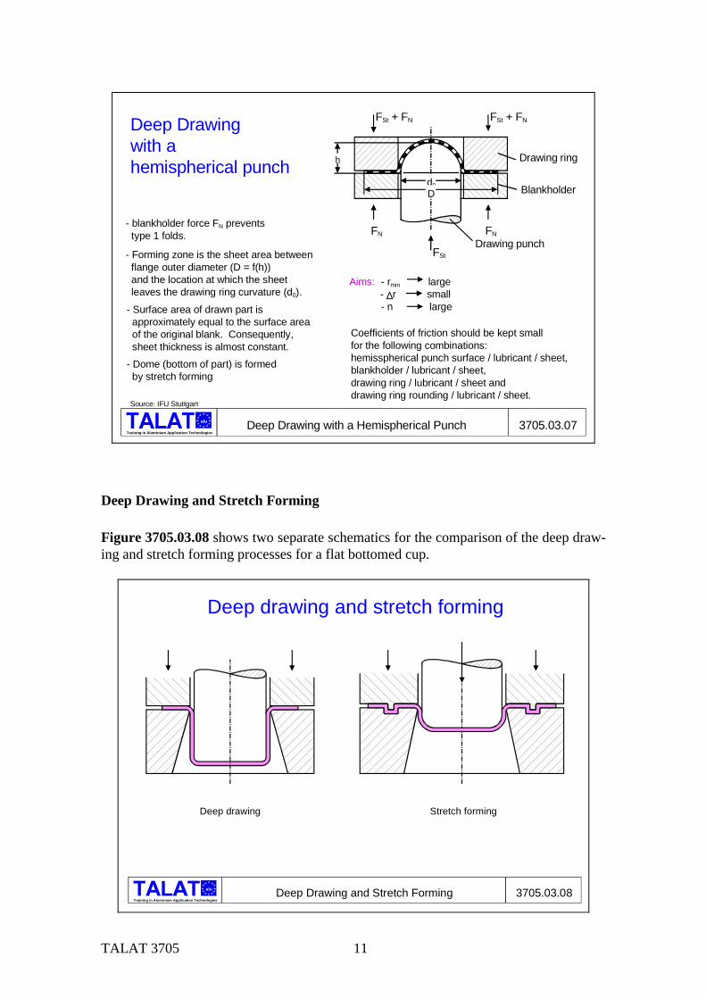
Deep Drawing with a Hemispherical Punch Figure 3705.03.07: In deep drawing with a hemispherical punch, the forming zone covers the region between the flange outer edge and the location where the drawing part leaves the drawing ring curvature. In contrast to stretch forming, the surface areas of the blank and the drawn part are about the same, so that the sheet thickness remains almost constant. The blankholder force prevents the formation of „type 1“ folds. The base of the drawing part is formed according to the principle of mechanical drawing. As far as the characteristic sheet values are concerned, large values for rmin and low values for ∆r are desirable. The strain hardening coefficient n should be as high as pos-sible. The coefficients of friction µ for the combinations punch/lubricant/sheet, blankholder/ lubricant/sheet, drawing ring/lubricant/sheet and drawing ring rounding/lubricant/sheet should be as low as possible.
TALAT 3705 11
alu
Training in Aluminium Application TechnologiesDeep Drawing with a Hemispherical Punch 3705.03.07
Source: IFU Stuttgart
FN
FSt
FSt + FN FSt + FN
FN
h
d0
Drawing ring
Blankholder
Drawing punch
D
Deep Drawing with a hemispherical punch
- blankholder force FN prevents type 1 folds.
- Forming zone is the sheet area between flange outer diameter (D = f(h)) and the location at which the sheet leaves the drawing ring curvature (d0).- Surface area of drawn part is approximately equal to the surface area of the original blank. Consequently, sheet thickness is almost constant.- Dome (bottom of part) is formed by stretch forming
Aims: - rmin large - ∆r small - n large
Coefficients of friction should be kept small for the following combinations:hemisspherical punch surface / lubricant / sheet,blankholder / lubricant / sheet,drawing ring / lubricant / sheet anddrawing ring rounding / lubricant / sheet.
Deep Drawing and Stretch Forming Figure 3705.03.08 shows two separate schematics for the comparison of the deep draw-ing and stretch forming processes for a flat bottomed cup.
alu
Training in Aluminium Application TechnologiesDeep Drawing and Stretch Forming 3705.03.08
Deep drawing and stretch forming
Deep drawing Stretch forming
TALAT 3705 12
Sheet metal parts with large surface areas are usually formed using a combination of deep drawing and stretch forming. A state of pure stretch forming exists only in very few cases. In such cases, the outer edge of the blank is clamped so that the increase in surface area can only come out of the sheet thickness. Deep drawing is the other extreme in which the blankholder holds the sheet so that it can flow in during forming. The sheet thickness remains approximately constant and the surface areas of the shaped part and the starting blank are about the same.
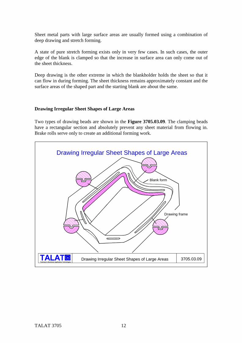
Drawing Irregular Sheet Shapes of Large Areas Two types of drawing beads are shown in the Figure 3705.03.09. The clamping beads have a rectangular section and absolutely prevent any sheet material from flowing in. Brake rolls serve only to create an additional forming work.
Training in Aluminium Application Technologies
alu Drawing Irregular Sheet Shapes of Large Areas 3705.03.09
Blank form
Drawing frame
Drawing Irregular Sheet Shapes of Large Areas
TALAT 3705 13
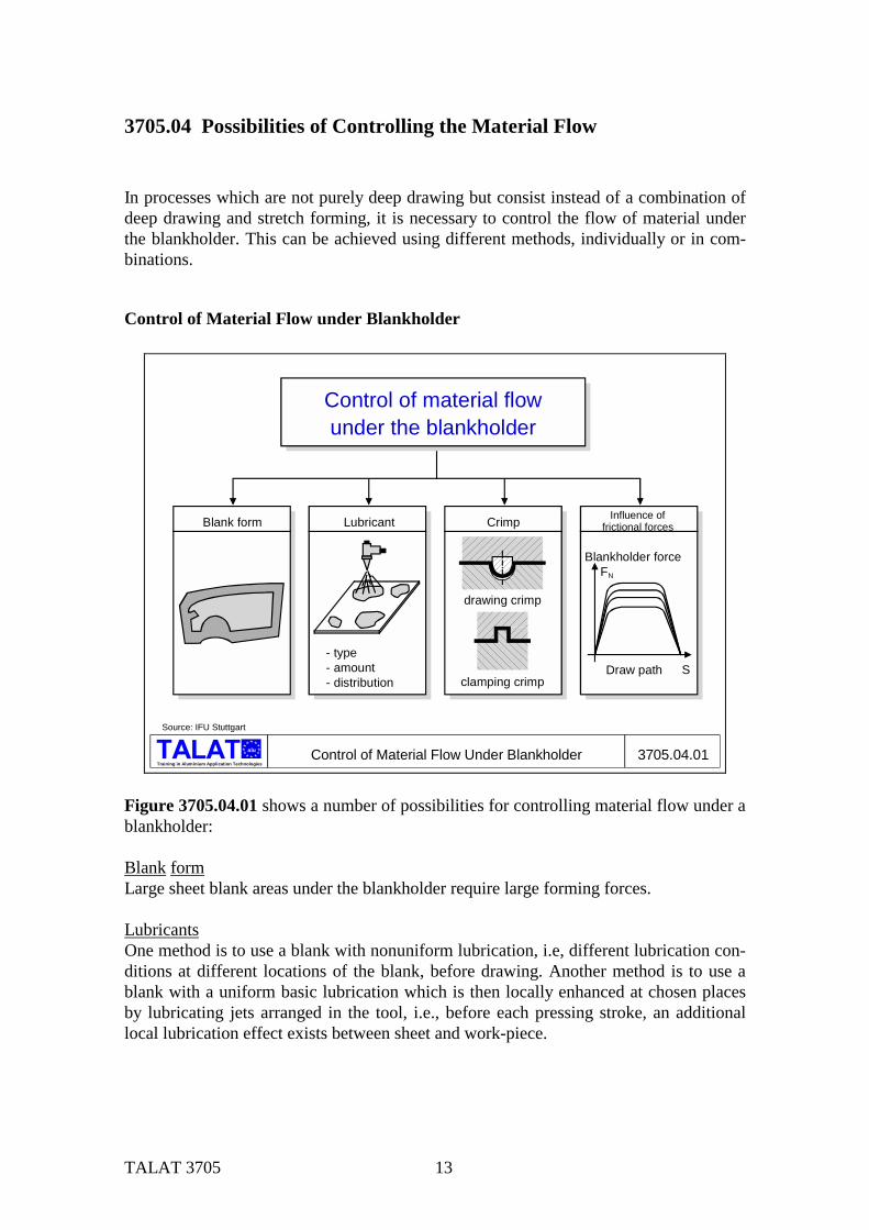
3705.04 Possibilities of Controlling the Material Flow In processes which are not purely deep drawing but consist instead of a combination of deep drawing and stretch forming, it is necessary to control the flow of material under the blankholder. This can be achieved using different methods, individually or in com-binations.
Control of Material Flow under Blankholder
alu
Training in Aluminium Application TechnologiesControl of Material Flow Under Blankholder 3705.04.01
Source: IFU Stuttgart
Control of material flowunder the blankholder
Blank form Lubricant
- type- amount- distribution
Influence offrictional forces
FN
S
Blankholder force
Draw path
Crimp
drawing crimp
clamping crimp
Figure 3705.04.01 shows a number of possibilities for controlling material flow under a blankholder: Blank form Large sheet blank areas under the blankholder require large forming forces. Lubricants One method is to use a blank with nonuniform lubrication, i.e, different lubrication con-ditions at different locations of the blank, before drawing. Another method is to use a blank with a uniform basic lubrication which is then locally enhanced at chosen places by lubricating jets arranged in the tool, i.e., before each pressing stroke, an additional local lubrication effect exists between sheet and work-piece.
TALAT 3705 14
Clamping crimps Clamping crimps hinder the flowing in of the material to varying degrees, depending on the form and size. It is thus possible to reduce the blankholder force, whereby the draw-ing force is increased. Influencing the frictional forces By regulating the blankholder force, it is possible to enhance or hinder the flow of mate-rial under it. This effect is obtained by locally varying the distance between blankholder and drawing frame, so that higher contact pressures can be brought to bear where the distance is smaller. Another possibility of controlling the material flow and consequently the deformation strain distribution during the drawing of irregular sheet shapes with varying draw depths, is by using brake rolls and draw beads. These hinder the flow of material by varying amounts, depending on their form and size. Again, it is possible to reduce the blankholder force, whereby the drawing force increases. As a result of the brake action of the draw beads, the material can no longer freely flow over the draw ring radius into the draw gap during the forming process. Thus it is possi-ble to reduce the stress differences between side walls and corner regions for compli-cated irregular shapes as well as for square shaped drawn parts. By optimally arranging the draw beads, one can control the material flow to create a uniform stress distribution such as occurs while fabricating cylindrical shapes. Brake rolls and draw beads ensure that the resistance of material flow over the draw ring radius into the draw gap varies locally, thus simulating the effect of increasing blankholder pressure. Depending on the design and arrangement in the tool, one can differentiate between draw beads and brake rolls. Draw beads are arranged at some distance from the drawing ring radius and cause, to-gether with the die radius, a three-fold directional change of the sheet. Draw beads can be arranged in both slanting and straight blankholder surfaces. Brake rolls are arranged at the die shoulder and create a two-fold directional change of the sheet material. Brake rolls in the draw ring are used mostly for round or oval sheet shapes with a parabolic or similar casing form.
TALAT 3705 15
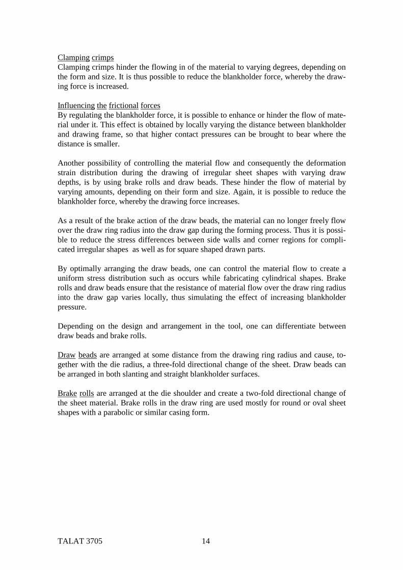
Arrangement of Draw Beads Figure 3705.04.02 shows the arrangement of draw beads for a drawn carbody compo-nent.
alu
Training in Aluminium Application TechnologiesArrangement of Draw Beads 3705.04.02
Arrangement of draw beads
10°10
°
10°a
b
a bSource: IfU Stuttgart
3705.05 Adjusting the Die Cushion
Mechanical vs. Hydraulic Press Equipment During drawing with a mechanical double-acting press (press with drawing punch ram and blankholder ram), the blankholder can be locally adjusted at the four points under the crank so that different contact pressures can be applied at the locations front left, front right, rear left and rear right under the blankholder, Figure 3705.05.01. A regula-tion, if at all possible, can only be carried out as far as the pressure is concerned. With the double-acting hydraulic press it is possible, without any great effort, to regulate the blankholder force during the draw path at each corner point, since each corner point has its own hydraulic cylinder.

TALAT 3705 16
alu
Training in Aluminium Application TechnologiesDrawing Equipment 3705.05.01
Source: IFU Stuttgart
a) Ram b) Blankholder ram c) Drawing punch d) Blankholder e) Counter pressure f) Mounting plate g)Hydraulic cylinder h) Air-cushion pins
Double action press Single action press with pneumatic drawing
equipment in the press table
Single action press with hydraulic drawing
equipment in the press table
a b
c
d
e
f
a
c
d
e
f
h
~ 20 x
a
c
d
e
f
g
4 x
Four-Point Die Cushion
alu
Training in Aluminium Application TechnologiesFour-Point Drawing Equipment 3705.05.02
Four-point drawing equipment
Source: IFU Stuttgart
press ram
tool top partblank
drawing tooltool platetool mounting platetable plate
proportional valve
hydraulic cylinder (4x)
bottom drawing frame(blankholder)
TALAT 3705 17
Figure 3705.05.02 together with the Figure 3705.05.01 illustrate that it is possible to draw parts using a three-piece tool not only with a two-fold acting press but also with a simple acting press. In these cases, the blankholder (lower drawing frame) is supported on a drawing form plate (cushion) form with the help of a number of pressure bolts. This drawing form plate is moved up and down or subjected to the blankholder force with the help of pneumatic or hydraulic cylinders.
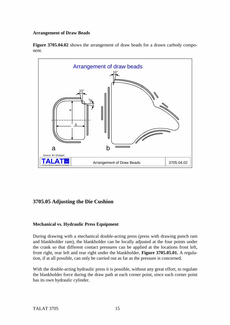
Desired and Actual Curves for Blankholder Force When the top frame contacts the blank lying on the lower frame, an undesirable force peak occurs, causing the lubricant film to break down, Figure 3705.05.03. In addition, this causes an undesirable overloading of the tool and machine and is a cause of noise. This undesirable force peak can be avoided by starting the drawing process with a lower pressure in the cylinders and then increasing this pressure to a level which prevents the formation of type-1 folds and allows the necessary material flow to be regulated.
Training in Aluminium Application Technologies
alu Desired and Actual Curves for Blankholder Force 3705.05.03
1000900800700600500400300200100
0210 120 60 15 0
120 135 150 165 180
Ram pathbefore UT [mm]
Crank angle [°]UT
Actual curve
Forc
e [k
N]
1000900800700600500400300200100
0210 120 60 15 0
120 135 150 165 180
Ram pathbefore UT [mm]
Crank angle [°]UT
Actual curve
Forc
e [k
N]
1000900800700600500400300200100
0
Required curve
Forc
e [k
N]
1000900800700600500400300200100
0
Required curve
Forc
e [k
N]
Source: IfU, Stuttgart
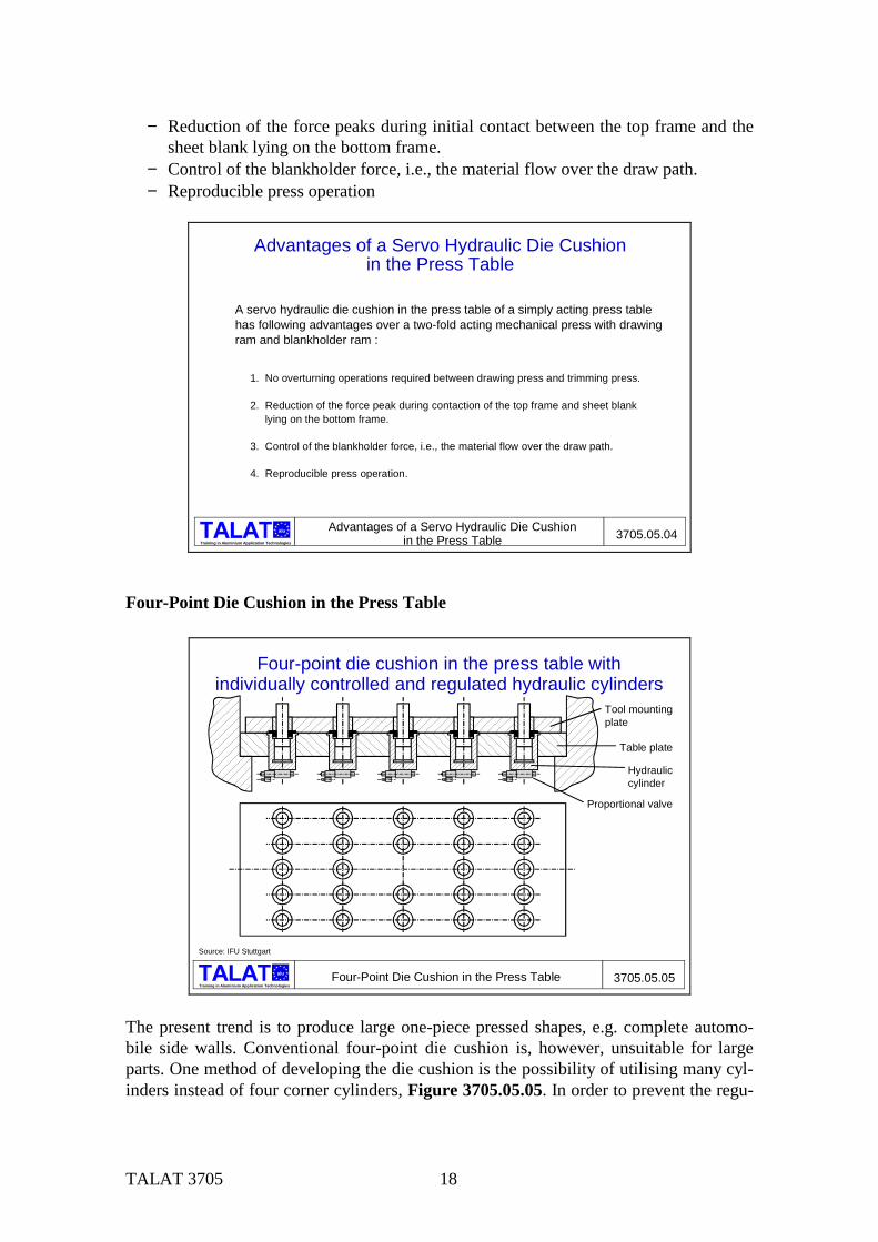
Advantages of a Servo-Hydraulic Die Cushion in the Press Table Figure 3705.05.04 summarises the advantages of a die cushion in the press table of a simple acting press over the mechanical double acting press with a drawing ram and a blankholder ram:
− No overturning operations required between drawing press and trimming press necessary.
TALAT 3705 18
− Reduction of the force peaks during initial contact between the top frame and the sheet blank lying on the bottom frame.
− Control of the blankholder force, i.e., the material flow over the draw path. − Reproducible press operation
Training in Aluminium Application Technologies
alu Advantages of a Servo Hydraulic Die Cushionin the Press Table 3705.05.04
Advantages of a Servo Hydraulic Die Cushionin the Press Table
A servo hydraulic die cushion in the press table of a simply acting press table has following advantages over a two-fold acting mechanical press with drawing ram and blankholder ram :
1. No overturning operations required between drawing press and trimming press.
2. Reduction of the force peak during contaction of the top frame and sheet blank lying on the bottom frame.
3. Control of the blankholder force, i.e., the material flow over the draw path.
4. Reproducible press operation.
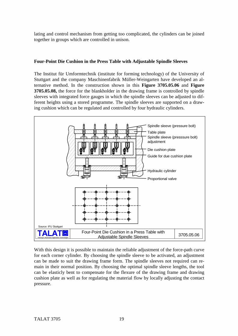
Four-Point Die Cushion in the Press Table
alu
Training in Aluminium Application TechnologiesFour-Point Die Cushion in the Press Table 3705.05.05
Tool mountingplate
Table plate
Hydrauliccylinder
Proportional valve
Four-point die cushion in the press table withindividually controlled and regulated hydraulic cylinders
Source: IFU Stuttgart
The present trend is to produce large one-piece pressed shapes, e.g. complete automo-bile side walls. Conventional four-point die cushion is, however, unsuitable for large parts. One method of developing the die cushion is the possibility of utilising many cyl-inders instead of four corner cylinders, Figure 3705.05.05. In order to prevent the regu-
TALAT 3705 19
lating and control mechanism from getting too complicated, the cylinders can be joined together in groups which are controlled in unison.
Four-Point Die Cushion in the Press Table with Adjustable Spindle Sleeves The Institut für Umformtechnik (institute for forming technology) of the University of Stuttgart and the company Maschinenfabrik Müller-Weingarten have developed an al-ternative method. In the construction shown in this Figure 3705.05.06 and Figure 3705.05.08, the force for the blankholder in the drawing frame is controlled by spindle sleeves with integrated force gauges in which the spindle sleeves can be adjusted to dif-ferent heights using a stored programme. The spindle sleeves are supported on a draw-ing cushion which can be regulated and controlled by four hydraulic cylinders.
alu
Training in Aluminium Application Technologies
Four-Point Die Cushion in a Press Table withAdjustable Spindle Sleeves 3705.05.06
Source: IFU Stuttgart
Spindle sleeve (pressure bolt)
Table plateSpindle sleeve (presssure bolt)adjustment
Die cushion plate
Guide for due cushion plate
Hydraulic cylinder
Proportional valve
With this design it is possible to maintain the reliable adjustment of the force-path curve for each corner cylinder. By choosing the spindle sleeve to be activated, an adjustment can be made to suit the drawing frame form. The spindle sleeves not required can re-main in their normal position. By choosing the optimal spindle sleeve lengths, the tool can be elasticly bent to compensate for the flexure of the drawing frame and drawing cushion plate as well as for regulating the material flow by locally adjusting the contact pressure.

TALAT 3705 20
Functional Principle of a Spindle Sleeve Adjustment Figure 3705.05.07: The adjustable spindle sleeves are supported against pressure gauges fitted on the drawing cushion plate. The spindle sleeves are adjusted by hydro motors, belt drive and spline shaft, whereby the height adjustment is recorded on a mo-ment controller.
alu
Training in Aluminium Application TechnologiesFunctional Principle of a Spindle Sleeve Adjustment 3705.05.07
Functional principle of a spindle sleeve adjustment
Source: IFU Stuttgart, Müller-Weingarten AG
Spindle sleeve (pressure bolt)
Table plate
Spindle sleeve adjusting spindle
Force gauge
Drawing cushion plate
Spline shaft
Toothed belt drive
Moment controller
Hydro motor
Experimental Construction of a Single Action Hydraulic Press (10-Point) Figure 3705.05.08 shows the experimental construction of a single action hydraulic press with a 10-point die cushion in the press table. For details refer to Figure 3705.05.06.
alu
Training in Aluminium Application Technologies
3705.05.08Experimental Construction of a Single Action Hydraulic Press (10-Point)
Experimental Construction of a Single Action Hydraulic Press (10-Point)
inductive path gaugewith feeler pin for folds measurement
extension gauges forflexure measurement
drawing tool
press tablefixing elements
extension gauges forpunch forcemeasurement
spindle sleeves (10)force gauge formeasuringblankholder force
Source: IfU Stuttgart
hydraulic diecushion
TALAT 3705 21
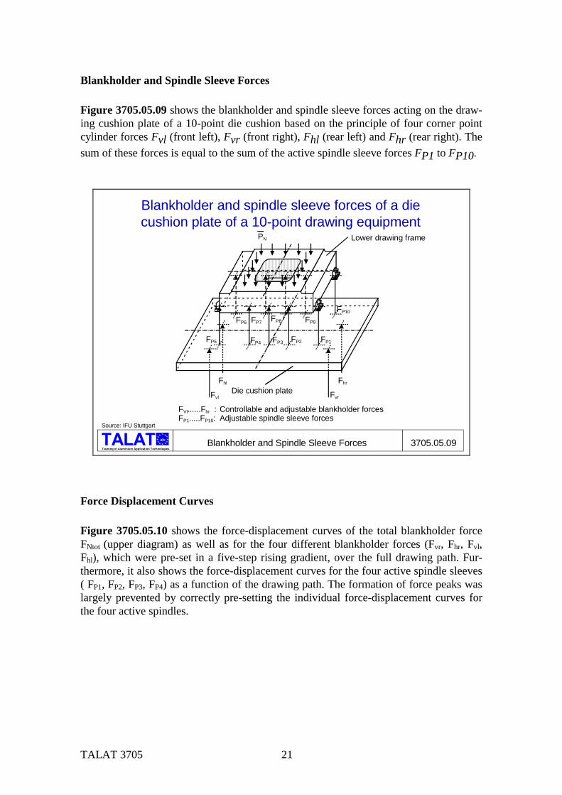
Blankholder and Spindle Sleeve Forces Figure 3705.05.09 shows the blankholder and spindle sleeve forces acting on the draw-ing cushion plate of a 10-point die cushion based on the principle of four corner point cylinder forces Fvl (front left), Fvr (front right), Fhl (rear left) and Fhr (rear right). The sum of these forces is equal to the sum of the active spindle sleeve forces FP1 to FP10.
alu
Training in Aluminium Application TechnologiesBlankholder and Spindle Sleeve Forces 3705.05.09
Blankholder and spindle sleeve forces of a diecushion plate of a 10-point drawing equipment
Source: IFU Stuttgart
Lower drawing frame
Die cushion plate
FVl......Fhr : Controllable and adjustable blankholder forcesFP1.....FP10: Adjustable spindle sleeve forces
Fvl
Fhl Fhr
Fvr
PN
FP1FP2FP3FP4FP5
FP6 FP7 FP8 FP9
FP10
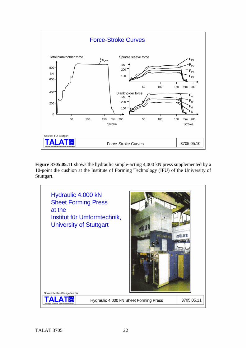
Force Displacement Curves Figure 3705.05.10 shows the force-displacement curves of the total blankholder force FNtot (upper diagram) as well as for the four different blankholder forces (Fvr, Fhr, Fvl, Fhl), which were pre-set in a five-step rising gradient, over the full drawing path. Fur-thermore, it also shows the force-displacement curves for the four active spindle sleeves ( FP1, FP2, FP3, FP4) as a function of the drawing path. The formation of force peaks was largely prevented by correctly pre-setting the individual force-displacement curves for the four active spindles.
TALAT 3705 22
Training in Aluminium Application Technologies
alu Force-Stroke Curves 3705.05.10
Force-Stroke Curves
800
600
400
200
050 100 150 200mm
kN
50 100 150 200mm
50 100 150 200mm
100
200kN
100
200kN
Total blankholder force Spindle sleeve force
Blankholder force
Stroke Stroke
FNges FP2
Fvr
FP9
FP4
FP7
Fhr
FvlFhl
Source: IFU, Stuttgart
Figure 3705.05.11 shows the hydraulic simple-acting 4,000 kN press supplemented by a 10-point die cushion at the Institute of Forming Technology (IFU) of the University of Stuttgart.
alu
Training in Aluminium Application Technologies
3705.05.11Hydraulic 4.000 kN Sheet Forming Press
Hydraulic 4.000 kN Sheet Forming Press at the Institut für Umformtechnik,University of Stuttgart
Source: Müller-Weingarten Co.
TALAT 3705 23
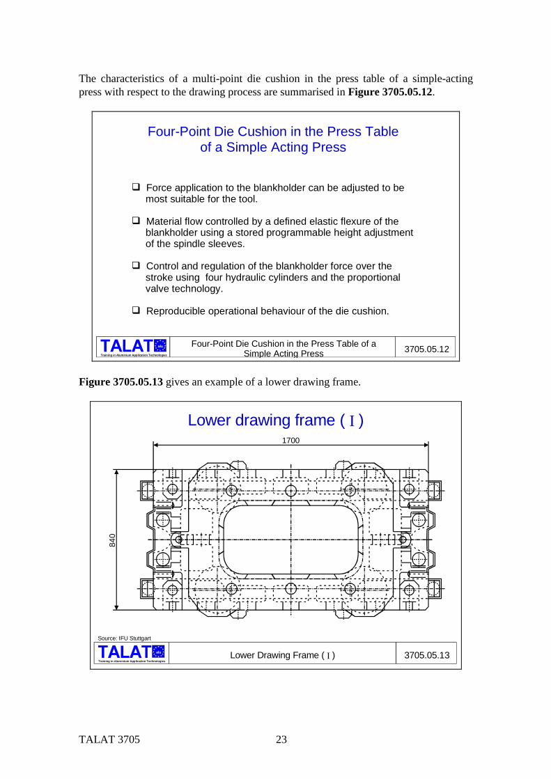
The characteristics of a multi-point die cushion in the press table of a simple-acting press with respect to the drawing process are summarised in Figure 3705.05.12.
Training in Aluminium Application Technologies
alu Four-Point Die Cushion in the Press Table of aSimple Acting Press 3705.05.12
Four-Point Die Cushion in the Press Tableof a Simple Acting Press
' Force application to the blankholder can be adjusted to be most suitable for the tool.
' Material flow controlled by a defined elastic flexure of the blankholder using a stored programmable height adjustment of the spindle sleeves.
' Control and regulation of the blankholder force over the stroke using four hydraulic cylinders and the proportional valve technology.
' Reproducible operational behaviour of the die cushion.
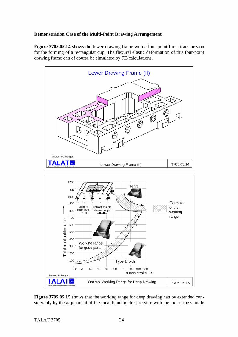
Figure 3705.05.13 gives an example of a lower drawing frame.
alu
Training in Aluminium Application TechnologiesLower Drawing Frame ( I ) 3705.05.13
Lower drawing frame ( I )
Source: IFU Stuttgart
1700
840
TALAT 3705 24
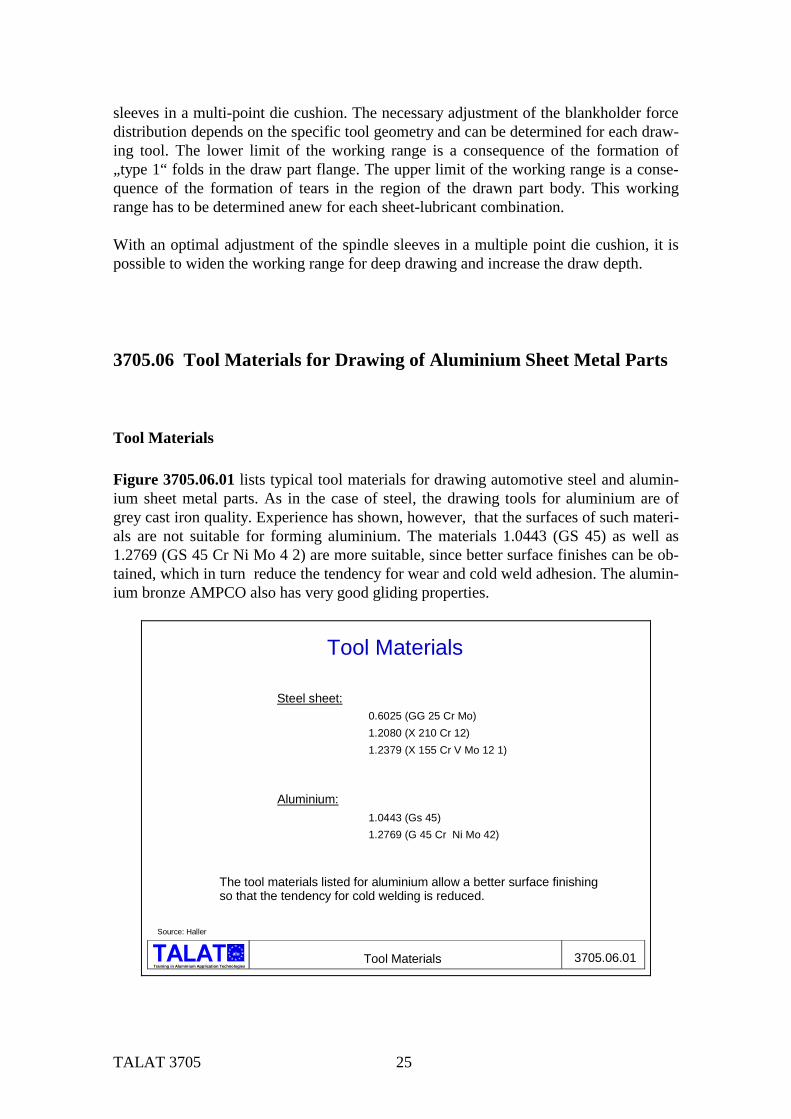
Demonstration Case of the Multi-Point Drawing Arrangement Figure 3705.05.14 shows the lower drawing frame with a four-point force transmission for the forming of a rectangular cup. The flexural elastic deformation of this four-point drawing frame can of course be simulated by FE-calculations.
Training in Aluminium Application Technologies
alu Lower Drawing Frame (II) 3705.05.14
Lower Drawing Frame (II)
Source: IFU Stuttgart
Extensionof theworkingrange
1200
1000
900
800
700
600
500
400
300
200
100
20 40 60 80 100 120 140 180mm
KN
0 0
FP1FP2FP3FP4FP5
FP6 FP7 FP8 FP9 FP10
3705.05.15Optimal Working Range for Deep Drawing
Source: IfU Stuttgart
optimal spindlesleeve height
punch stroke
Tota
l bla
nkho
lder
forc
e
alu
Training in Aluminium Application Technologies
uniform force level
Working rangefor good parts
Type 1 folds
Tears
Figure 3705.05.15 shows that the working range for deep drawing can be extended con-siderably by the adjustment of the local blankholder pressure with the aid of the spindle
TALAT 3705 25
sleeves in a multi-point die cushion. The necessary adjustment of the blankholder force distribution depends on the specific tool geometry and can be determined for each draw-ing tool. The lower limit of the working range is a consequence of the formation of „type 1“ folds in the draw part flange. The upper limit of the working range is a conse-quence of the formation of tears in the region of the drawn part body. This working range has to be determined anew for each sheet-lubricant combination. With an optimal adjustment of the spindle sleeves in a multiple point die cushion, it is possible to widen the working range for deep drawing and increase the draw depth.
3705.06 Tool Materials for Drawing of Aluminium Sheet Metal Parts
Tool Materials Figure 3705.06.01 lists typical tool materials for drawing automotive steel and alumin-ium sheet metal parts. As in the case of steel, the drawing tools for aluminium are of grey cast iron quality. Experience has shown, however, that the surfaces of such materi-als are not suitable for forming aluminium. The materials 1.0443 (GS 45) as well as 1.2769 (GS 45 Cr Ni Mo 4 2) are more suitable, since better surface finishes can be ob-tained, which in turn reduce the tendency for wear and cold weld adhesion. The alumin-ium bronze AMPCO also has very good gliding properties.
Training in Aluminium Application Technologies
alu Tool Materials 3705.06.01
Tool Materials
Steel sheet:0.6025 (GG 25 Cr Mo)1.2080 (X 210 Cr 12)1.2379 (X 155 Cr V Mo 12 1)
Aluminium:1.0443 (Gs 45)1.2769 (G 45 Cr Ni Mo 42)
The tool materials listed for aluminium allow a better surface finishing so that the tendency for cold welding is reduced.
Source: Haller
TALAT 3705 26
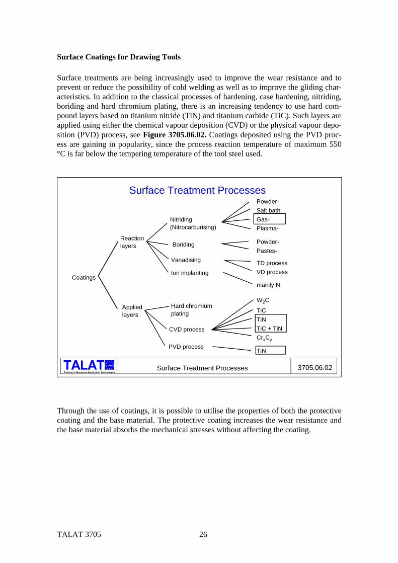
Surface Coatings for Drawing Tools Surface treatments are being increasingly used to improve the wear resistance and to prevent or reduce the possibility of cold welding as well as to improve the gliding char-acteristics. In addition to the classical processes of hardening, case hardening, nitriding, boriding and hard chromium plating, there is an increasing tendency to use hard com-pound layers based on titanium nitride (TiN) and titanium carbide (TiC). Such layers are applied using either the chemical vapour deposition (CVD) or the physical vapour depo-sition (PVD) process, see Figure 3705.06.02. Coatings deposited using the PVD proc-ess are gaining in popularity, since the process reaction temperature of maximum 550 °C is far below the tempering temperature of the tool steel used.
Training in Aluminium Application Technologies
alu Surface Treatment Processes 3705.06.02
Surface Treatment Processes
Coatings
Reactionlayers
Appliedlayers
Nitriding(Nitrocarburising)
Boriding
Vanadising
Ion implanting
Hard chromiumplating
CVD process
PVD process
Powder-Salt bathGas-Plasma-
Powder-Pastes-
TD processVD process
mainly N
W2C
TiCTiNTiC + TiNCrxCy
TiN
Through the use of coatings, it is possible to utilise the properties of both the protective coating and the base material. The protective coating increases the wear resistance and the base material absorbs the mechanical stresses without affecting the coating.
TALAT 3705 27
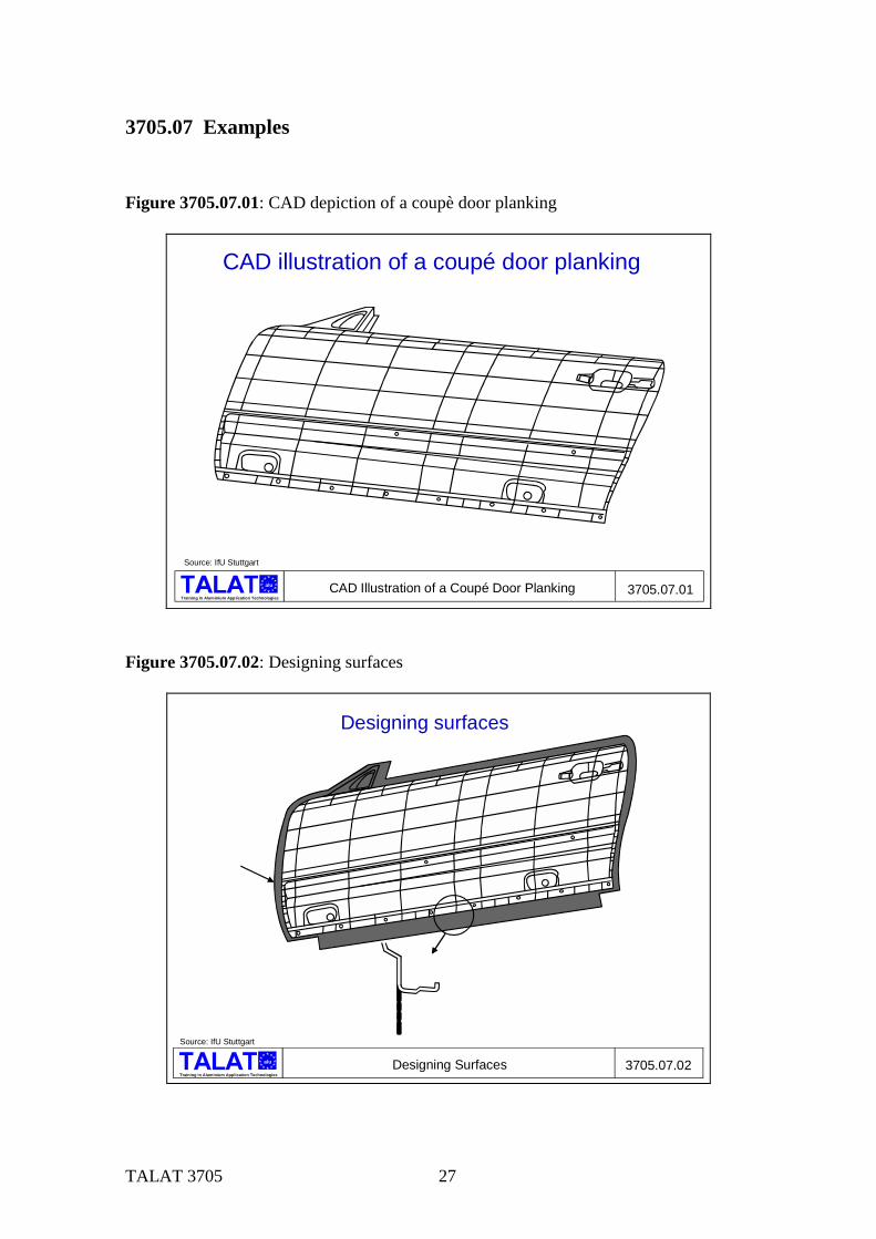
3705.07 Examples Figure 3705.07.01: CAD depiction of a coupè door planking
alu
Training in Aluminium Application Technologies3705.07.01
Source: IfU Stuttgart
CAD Illustration of a Coupé Door Planking
CAD illustration of a coupé door planking
Figure 3705.07.02: Designing surfaces
alu
Training in Aluminium Application Technologies3705.07.02
Source: IfU Stuttgart
Designing Surfaces
Designing surfaces
TALAT 3705 28
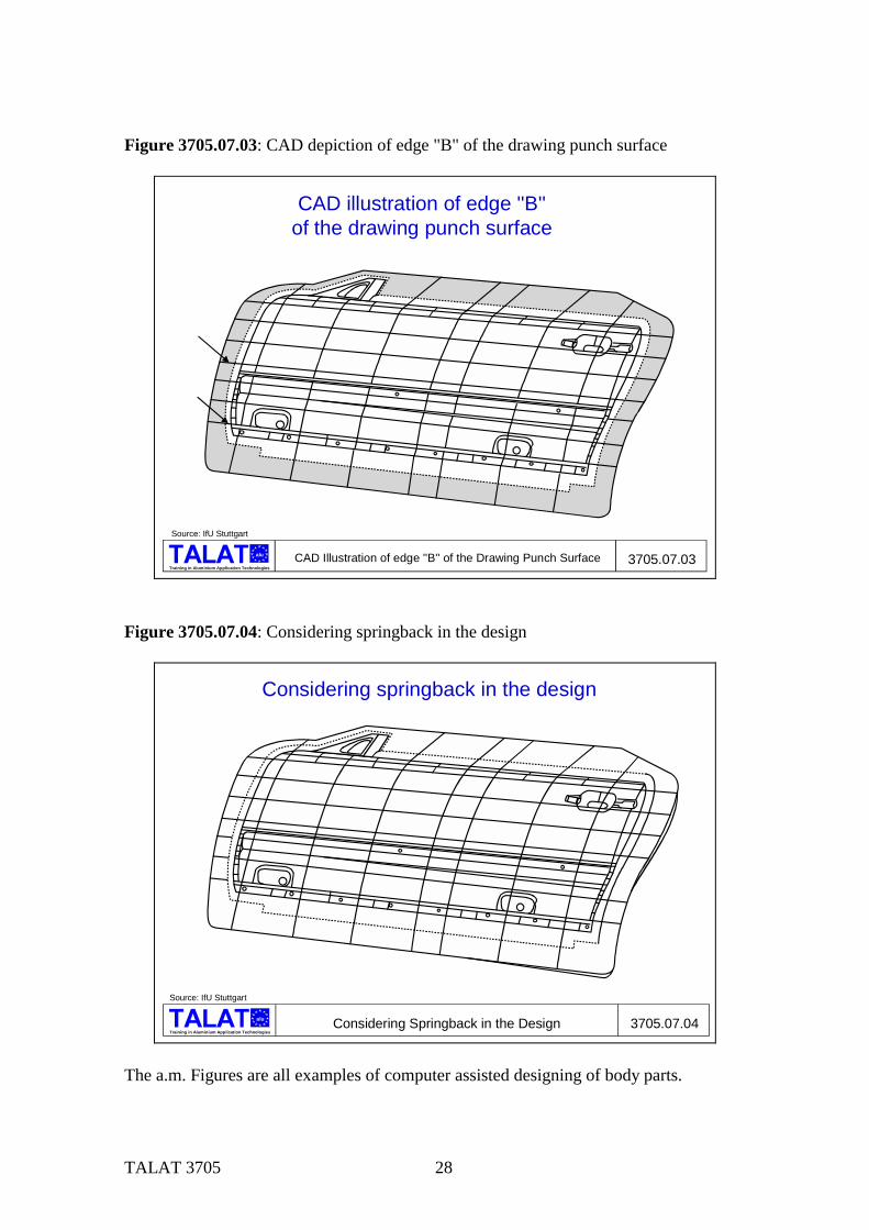
Figure 3705.07.03: CAD depiction of edge "B" of the drawing punch surface
alu
Training in Aluminium Application Technologies3705.07.03
Source: IfU Stuttgart
CAD Illustration of edge ''B'' of the Drawing Punch Surface
CAD illustration of edge ''B'' of the drawing punch surface
Figure 3705.07.04: Considering springback in the design
alu
Training in Aluminium Application Technologies3705.07.04
Source: IfU Stuttgart
Considering Springback in the Design
Considering springback in the design
The a.m. Figures are all examples of computer assisted designing of body parts.
TALAT 3705 29
3705.08 List of Figures Figure No. Figure Title (Overhead) 3705.01.01 Forecast for the Year 2000 3705.02.01 Influence of Cold Work and Simulated Lacquer Stoving on Yield
Strength 3705.02.02 Effect of r-Value on Yield Locus 3705.02.03 Elongation Values for AlMgSi1-ka in Polar Coordinates 3705.02.04 Vertical Anisotropy r for AlMg5Mn-w as a Function of Rolling Direction 3705.03.01 Stretch Forming 3705.03.02 Mechanical Drawing 3705.03.03 Strain-Path Curves for Mechanical Drawing 3705.03.04 Hydraulic Drawing 3705.03.05 Strain-Path Curves for Hydraulic Drawing 3705.03.06 Comparison of the Principal Strains ϕg for Mechanical and Hydraulic
Drawing 3705.03.07 Deep Drawing with a Hemispherical Punch 3705.03.08 Deep Drawing and Stretch Forming 3705.03.09 Drawing Irregular Sheet Shapes of Large Areas 3705.04.01 Control of Material Flow under Blankholder 3705.04.02 Arrangement of Draw Beads 3705.05.01 Drawing Equipment 3705.05.02 Four-Point Drawing Equipment 3705.05.03 Desired and Actual Curves for Blankholder Force 3705.05.04 Advantages of a Servo Hydraulic Die Cushion in the Press Table 3705.05.05 Four-Point Die Cushion in the Press Table 3705.05.06 Four-Point Die Cushion in a Press Table with Adjustable Spindle Sleeves3705.05.07 Functional Principle of a Spindle Sleeve Adjustment 3705.05.08 Experimental Construction of a Simple Acting Hydraulic Press (10-
Point)) 3705.05.09 Blankholder and Spindle Sleeve Forces 3705.05.10 Force-Stroke Curves 3705.05.11 A Hydraulic 4,000 kN Sheet Forming Press 3705.05.12 Four-Point Die Cushion in the Press Table of a Simple Acting Press 3705.05.13 Lower Drawing Frame (I)) 3705.05.14 Lower Drawing Frame (II) 3705.05.15 Optimal Working Range for Deep Drawing 3705.06.01 Tool Materials

TALAT 3705 30
Figure No. Figure Title (Overhead) 3705.06.02 Surface Treatment Processes 3705.07.01 CAD Illustration of a Coupè Door Planking 3705.07.02 Designing Surfaces 3705.07.03 CAD Illustration of Edge "B" of the Drawing Punch Surface 3705.07.04 Considering Springback in the Design