Embed Size (px)
Citation preview

CHAPTER
3
Project Navigatorfor MEP
INTRODUCTION
In this chapter, we will explore the Drawing Management features of AutoCAD MEP(AMEP). Drawing Management is the official formal name for a series of tools that facili-tate the collection and management of the various drawing files required in a typical proj-ect. Broken into two tools, Project Browser and Project Navigator, the toolset providesmany benefits including easy XREF creation and management, centralization of projectfiles, automation of repetitive tasks and more. Project Browser is used to create andload projects and Project Navigator is used for everything else. It is not required thatyou use Project Navigator (Drawing Management) to use AMEP, but doing so can helpencourage the use of standards and procedures in your project teams.
OBJECTIVES
In this chapter, we will explore the Drawing Management features of AMEP. We have al-ready seen a simple project configured using Project Navigator in the Quick Start chap-ter. In the remaining chapters, we will explore many of the AMEP tools within the contextof a small commercial office building project. If you are familiar with Mastering AutoCADArchitecture, you will have seen this building project before. This project represents butone way that Project Navigator can be used to help enhance your AMEP experience. Wewill explore many of the critical concepts in this chapter, including the following:
• Building comfort with Drawing Management.
• Exploring and understanding provided drawing files.
• Learning to set up callouts, elevations and sections.
• Working with Sheets and Sheet Sets.
BUILDING A DIGITAL CARTOON SETWhen the time comes in a project cycle to begin thinking about how many sheets ofdrawings will be required and what those sheets will contain, it is time to build a digi-tal cartoon set. Just like the traditional paper-based cartoon set, the digital version willhelp you make good decisions about project documentation requirements and the
133
© C
enga
ge L
earn
ing.
All
right
s res
erve
d. N
o di
strib
utio
n al
low
ed w
ithou
t exp
ress
aut
horiz
atio
n.

impact on budget and personnel considerations. One extra advantage of the digitalcartoon set is that it is the actual set of electronic files for the project and will evolveas the project develops. This means that the layout of a cartoon set is actually the lay-out of the real building model and eventual document set! Don’t be concerned withthe finality that this seems to imply. The documents remain completely flexible andeditable, making this approach consistent with the goal of progressive refinement asdefined in Chapter 2.
CAUTION Please do not skip this step when setting up your own projects. Establishing the digital car-toon set (or the Building Information Model structure) at the beginning of a project is criti-cal to maximizing the potential of the AMEP tools and methods, and will go a long waytoward ensuring success.
Typical projects usually involve a heavy dose of external references (XREFs). Settingthese up can be time consuming. However, using the Drawing Management systemin AMEP, the use of XREFs is made easy and nearly transparent. You will find thatmost of the work associated with the attachment and maintenance of the requiredXREFs is handled automatically and intelligently by the software.
In many ways, the task of creating a digital cartoon set is no more complicated thansimply setting up Project Navigator. If you set up all your files early, you can print thedigital cartoon set at the start of the project and use it to help staff the project teamproperly. Furthermore, you will benefit later in the project when your team is not bur-dened with having to pause productive work to stop and build a required file. If thesetup is performed carefully, the team will have most of the files they require at theearliest stages of the project. Naturally, there will always be file needs discovered laterin the project, but simply attempting to build everything early will go a long way to-ward minimizing the quantity of files required later.
DRAWING MANAGEMENT FEATURES AND BENEFITSAs you probably know, AMEP is built on top of the AutoCAD Architecture (ACA)platform. Project Navigator is a tool provided in the core ACA package and, as such,shared by all disciplines that use ACA or AMEP. We note this here simply to makethe point that some of the features of the Drawing Management system are morebeneficial to the architectural workflow than engineering. This is not to say that thetools are not useful to engineers; rather that we will focus our coverage in this chapteron those tools and features that offer the most benefit to engineers.
To help us understand the Drawing Management system and Project Navigatorfunctionality, a project has been provided with the book CD ROM. The project is asmall (30,000 SF) commercial office building. The project is mostly core and shellwith some build-out occurring on one of the tenant floors.
The DrawingManagement system offers many features and benefits. Using DrawingManagement gives you a logical and easy-to-use interface for all your AMEP pro-jects, both large and small. Drawing Management formalizes the relationship be-tween several disparate files used to create the typical project. While DrawingManagement is not required to use the other features of AMEP, doing so allowsyou to gain the fullest benefits from the software. Most of the tools that would other-wise be separate and disparate functions come together into a unified process through
134 The Aub in A c ad emy Ma s t e r S e r i e s : Au t oCAD MEP 2011
© C
enga
ge L
earn
ing.
All
right
s res
erve
d. N
o di
strib
utio
n al
low
ed w
ithou
t exp
ress
aut
horiz
atio
n.

the Drawing Management system. Drawing Management offers the following keyfeatures:
Level Management—You establish each floor level in the Project Navigator, thesoftware will manage inserting all XREFs at the correct floor heights in all projectfiles.
Clear Delineation of Project Components—Using Constructs, Views and Sheets,AMEP presents a clear standard for the location of model components, adding anno-tation and plotting.
Ease of Use—Project Navigator introduces drag and drop ease to XREF Manage-ment. Simply drag a file from Project Navigator and the software takes care of therest.
Maintains a Project Database—All project files are tracked and maintained in Proj-ect Navigator. In addition, a comprehensive list of project data are maintained andcan be fed to project schedules, tags, title blocks and field codes.
Automated View and Sheet creation—You first determine the structure of yourbuilding (create its Constructs). Creating plans and sections, adding annotation andbuilding Sheets is easy with a simple wizard interface and drag and drop.
Integration of the AutoCAD Sheet Set functionality—Sheet Set functionality isfully integrated into Project Navigator making the organization, publishing, eTrans-mitting, archiving and plotting of Sheets easy and powerful.
Automatic Repathing and View Regeneration—Whenever a change to a file loca-tion or a file name occurs, Project Navigator can automatically repath all XREFs inthe project. In addition, whenever a structural change to the building model is made,such as a change in level or the addition of a new construct, the software will auto-matically regenerate associated views to reflect the change.
PROJECT BROWSERThe Project Browser is a file browser mechanism that allows you to locate project files(APJ files) anywhere on your computer (local or network). Using the Project Browser,you can locate projects and make them current. You can also move, copy and createnew projects in this tool. Whether you need to load an existing project or create a newone, both tasks are accomplished with the Project Browser.
By default, when you install AMEP, a folder named Autodesk that contains a sub-folder named My Projects will be created in the current user’s My Documents folder.When you open the Project Browser for the first time, it will be set to this location.However, if you completed the Quick Start chapter, it will remember the location ofthe last project that you had loaded and show that location instead.
It is not necessary that you create projects in the My Documents location and, in fact,in a team environment it is preferable to work from a network server location instead.Dataset files installed from the Aubin Academy Master Series: AutoCAD MEP 2011
student companion are installed in the C:\MasterAMEP 2011 folder (see the “Filesincluded with the Student Companion” topic of the Preface for more information).Even though you will typically work from a server location on your real projects, forthe tutorials in this book, it is highly recommended that you work in this location.
Chap t e r 3 • Pr o j e c t Nav i g a t o r f o r MEP 135
© C
enga
ge L
earn
ing.
All
right
s res
erve
d. N
o di
strib
utio
n al
low
ed w
ithou
t exp
ress
aut
horiz
atio
n.

Descriptions of each item in the dialog are as follows:
a. Project Image—A custom-defined BMP image can be assigned to the projectand displayed here. For example, load the client’s logo here.
b. Current Project Info—The Name, Number and Description of the current proj-ect will display here.
c. Back—Click to go back to the previous folder.
d. Up One Level—Click to go to parent folder.
e. Create a New Folder—Create a new folder in the current location.
f. Browse Project—Click to open a standard Browse Window to locate and loadproject files (AMEP projects have an APJ extension).
g. Project History—Click to browse for projects that were previously active (usethe drop-down list for additional history view options). While in the Historyview, you can right-click and remove items from the history list as well as resetthe list.
h. Project Folder—Click to browse for projects within the folder tree. This optiongives access to My Computer, My Documents and Network locations such asmapped drives and any additional locations that you add to the AEC Project Lo-cation Search Path.
i. Project Bulletin Board—The user-defined Project Bulletin Board Web Page, afully customizable project-specific HTML Web page. AMEP starts with a simplegeneric page; you can load your own custom one in the Project properties.
j. New Project—Creates a new project within the current folder.
k. Refresh Project—Refreshes the current folder.
l. Project Bulletin Board Navigation Tools—Typical browser functions for thebulletin board page.
FIGURE 3.1 The Project Browser window
136 The Aub in A c ad emy Ma s t e r S e r i e s : Au t oCAD MEP 2011
© C
enga
ge L
earn
ing.
All
right
s res
erve
d. N
o di
strib
utio
n al
low
ed w
ithou
t exp
ress
aut
horiz
atio
n.

MANAGERNOTE
You can add to the default search path locations used by the Project Browser in the“Options” dialog box. From the Application Menu choose Options, and then click the AECProject Defaults tab. There you can add paths to the AEC Project Location Search Path.You can also edit the default Project Templates, Project Bulletin Boards and Project Imageson this screen. It is recommended at the time of installation that you reset these paths forusers to a location on the server where project templates and files are typically stored.
Once you have loaded or created your project, you do not need to open ProjectBrowser again until you need to switch projects. From then on, you will do all yourDrawing Management tasks using Project Navigator.
PROJECT NAVIGATORThe Project Navigator palette (open from the Quick Access Toolbar) provides thecomplete interface to all files used in a project. Use Project Navigator to set up Levelsand Divisions and to create, open and XREF Constructs, Elements, Views and Sheets(see below for terminology). Project Navigator behaves like other AutoCAD palettesand may be docked, floating, transparent and set to auto-hide (see Figure 3.2).
Projects are organized into several kinds of files named: Constructs, Elements, Viewsand Sheets. The Project Navigator palette contains tabs to manage each of these(Constructs and Elements are both found on the Constructs tab) and the Projecttab for managing the project’s overall parameters, such as Levels and Divisions. Iconsappear along the bottom of each tab for common functions. More tools and com-mands are available in the right-click menu of the file list (shown on the right ofFigure 3.2). Right-click menus vary on each tab like the bank of icons along the bot-tom. Take some time to pause over each tool to see a tooltip explaining the functionand right-click in several locations to become familiar with the menus.
PROJECT NAVIGATOR TERMINOLOGYProjects in AMEP consist of a collection of drawing files and project informationfiles saved together in a common location. Taken together, this collection of graphical
FIGURE 3.2 The Project Navigator palette
Chap t e r 3 • Pr o j e c t Nav i g a t o r f o r MEP 137
© C
enga
ge L
earn
ing.
All
right
s res
erve
d. N
o di
strib
utio
n al
low
ed w
ithou
t exp
ress
aut
horiz
atio
n.

and non-graphical data is used to assemble a complete Building Information Model(BIM). The graphical drawing data associated with the project fall into four types ofAMEP drawing (DWG) files: Constructs, Elements, Views and Sheets.Each is definedbelow. The non-graphical project information files include a single Autodesk ProjectInformation file (APJ) that contains the basic framework of a project, a Sheet Set file(DST) that determines the organization and configuration of the list of printedSheets within the project, and several individual project data (XML) files (one perdrawing) describing how each individual drawing fits into the overall projectstructure.
When you create a project, you enter the basic descriptive information, such as Name,Description and Project Number. The next task is to determine how the building willbe subdivided into Levels and Divisions. Levels are the floor Levels and divide thebuilding horizontally. You can also subdivide the building laterally into Divisions.Although you can edit Levels and Divisions at any time, it is typical to establish theLevels and Divisions that will describe the basic framework of your project at the on-set. These tasks are performed in the Project Navigator.
TIP If Project Navigator did not appear automatically onscreen when you created the project,click the Project Navigator icon on the QAT.
Levels and Divisions (Project Framework)• Level—A horizontal separation of the building model data. A Level is typi-
cally an actual floor level in a building. Levels can be established for actualbuilding stories, and also for mezzanines, basements and other partial levels.You also use Levels to establish Grade level, Roofs and Datum levels (seeFigure 3.3).
• Division—A vertical separation of the building model data. Divisions are typi-cally used to articulate a physical separation such as a wing, an annex, or anaddition to a building. Divisions can be used to subdivide large floor platesinto pieces that are more manageable in size (See Figure 3.3). Projects fre-quently have only a single division.
138 The Aub in A c ad emy Ma s t e r S e r i e s : Au t oCAD MEP 2011
© C
enga
ge L
earn
ing.
All
right
s res
erve
d. N
o di
strib
utio
n al
low
ed w
ithou
t exp
ress
aut
horiz
atio
n.

NOTESee next topic for a definition of Construct.
Model and Sheet FilesStandard industry practice and the US National CAD Standard (NCS) recommendthe creation and maintenance of two types of files: Model files and Sheet files. Thispractice is widely used in the industry and offers many benefits.
• Model File—A file containing actual building data drawn at full size (1 to 1 scale).This is a file in which all of the day-to-day work is typically performed. In theAMEP Drawing Management system, Constructs, Elements and Views can allbe considered Models in the traditional sense (see definitions later).
• Sheet File—A file that is used exclusively for printing drawings. No data is savedin this file. It typically contains only a title block and external references to theproject’s various Model files.
Model files are referenced to Sheet files for printing (or when appropriate, otherModel files). Most daily work is performed in Model files. In contrast, Sheet filesexist solely for printing final documentation sets for distribution. One or moreModelfiles are “gathered” by the Sheet file, composed on a title block sheet, scaled with theproper Display Configuration (see Chapter 2) active, layers and objects visible, andthen printed. The Sheet is saved in this state so that documents can be printed againany time, at a moment’s notice. To perform physical edits and design changes, return
FIGURE 3.3 Divide your building into Levels and Divisions to create your project structure
Chap t e r 3 • Pr o j e c t Nav i g a t o r f o r MEP 139
© C
enga
ge L
earn
ing.
All
right
s res
erve
d. N
o di
strib
utio
n al
low
ed w
ithou
t exp
ress
aut
horiz
atio
n.

to Model files and perform the changes there. Those changes will appear in the Sheetfile the next time the XREFs in that Sheet are reloaded, which happens automaticallywhen the Sheet is opened.
CAUTION The Sheet file’s “ready-to-print” status is maintained only if all project team members agreeto work only in Model files and not in the Sheet files.
Constructs, Views and Sheets (Project Drawing Files)AMEP formalizes the creation of project files based on the Model/Sheet concept inthe DrawingManagement system and accompanying procedures. This system incor-porates the industry-standard use of Model and Sheet files and introduces an addi-tional layer of granularity (Elements, Constructs and Views) to help formalize theprocess.
• Element—(Mostly used in Architecture) A discrete piece of a design without ex-plicit physical location within the building. Often an Element represents compo-nents that are repeated more than once in the design (typicals). Elements arealso ideal for storage of project resources that you wish to have readily accessi-ble. Elements are drawing files that are XREFed to other files (Constructs,Views, Sheets, or even other Elements) as project needs dictate.
• Construct—A discrete piece of a design with explicit physical location withinthe building. More specifically, it is a unique piece of the building occurringwithin a particular zone (Division) on a specific floor (Level) of the building.Constructs are not specific to any particular type of drawing. They are not“Plans” or “Sections” but rather Models that can be used to generate plans, sec-tions, or any other type of drawing. A Construct is distinguished from an Ele-ment by its uniquely identifiable physical location within the building.Constructs are drawing files that are XREFed to other files (other Constructs,Views and Sheets) as project needs dictate.
• View—A slice of the building model configured to match a standard engineer-ing drawing type. A View gathers all of the Constructs (and their nestedElements) required to correctly represent a specific portion (or slice) of thebuilding. Views are akin to a particular type of drawing such as a “plan” or“section,” and will contain those project annotations like notes, dimensionsand tags appropriate to the drawing type and scale in question. Views are draw-ing files containing XREFs of Constructs that are, in turn, XREFed into Sheets asproject needs dictate. Views provide a bridge between general model data inConstructs and the Sheets upon which they will be printed.
For example, imagine a three-story commercial building. You would have at least oneConstruct for each floor and discipline, although there could be, and often are, sev-eral. For instance, you might have a separate Lighting and Power Construct. A simi-lar structure would be established for each of the other floors.When you were ready tobegin creating construction documents to communicate your design, you would startcreating drawing-specific Views. A View allows you to create a unique snapshot of aportion of the building. For instance, if you wished to work on the Third Floor EastWing in section, you would create and work in a View that would gather and correctlyrepresent all of the Constructs required by that physical portion of the building. Viewscan be made to accommodate the creation of Plans, Sections, Elevation, Schedules,Details, and even full 3D Models. Be careful, however, to distinguish the “working”nature of Views from the “output” or plotting nature of Sheets. In other words, westill perform edits in Views, but Sheets are for plotting only.
140 The Aub in A c ad emy Ma s t e r S e r i e s : Au t oCAD MEP 2011
© C
enga
ge L
earn
ing.
All
right
s res
erve
d. N
o di
strib
utio
n al
low
ed w
ithou
t exp
ress
aut
horiz
atio
n.

• Sheet—A “just for printing” view of the building model. While Elements, Con-structs, and Views can all be considered Models as defined by NCS/AIA, theAMEP Sheet exactly emulates the purpose and intent of the NCS/AIA recom-mended Sheet file as noted previously. A Sheet file will gather all required build-ing model components (Views and/or Constructs) and compose them on a titleblock sheet at a particular scale, ready to print.
There are those who argue that annotation and dimensions ought to be placed in theSheets. Some go further to propose that these items be placed in the Layout (PaperSpace) on top of viewport images of the project files. While both these approaches arecertainly possible, the AMEPDrawingManagement toolset instead supports the ap-proach championed by this text as indicated in the earlier definition of “Sheet.” It isthe position of this text that Sheets should be set up once and maintained from thenon as “for plotting only” files. The goal is to provide a set of files (one for each physicalpaper sheet in a document set) that is always ready to be opened and printed with noadvance notice or tweaking required.
When project team members are allowed (or encouraged) to work in sheet files, it ispossible or even likely that they will leave the drawings in a state that is less than idealfor “ready printing.” For instance, one might close the drawing with model space ac-tive, or change the LtScale, or accidentally forget to freeze or thaw the correct layers.These are just some examples of the types of mundane settings that, if incorrectly setat the time of plotting, can result in the necessity of reprinting a drawing. Not only isthis frustrating to the person making the plots, but it needlessly wastes time, paperand money. It is therefore strongly recommended that Sheets be used for plottingonly, and all daily work be done in Constructs and/or Views. To help you achievethis goal, the “Match Sheet View Layers to View” feature when turned on (in the“Project Properties” dialog) will synchronize all changes in the View files to the cor-responding Sheet viewports automatically.
FILE NAMING STRATEGYFile naming strategies and organization vary from company to company, (and regionto region). However, as different as the naming scheme in one firm might be fromthat of another down the block, there are many similarities from firm to firm. Inmost cases, you will be able to adapt easily your existing scheme into the use of Project
TO VIEW OR NOT VIEW…
AMEP offers many automated routines that makecreating section Views or detail Views quick andeasy. Plans, on the other hand, offer some uniquechallenges with respect to Views. Since manyAMEP objects offer automatic annotation as an in-tegral part of the object, such as Duct and Pipe labelsand Device tags, many engineering firms opt toannotate directly in Constructs for plan drawings.Doing so offers advantages and disadvantages.With annotation so closely related to the model ele-ments in plan drawings, working with both in theConstruct offers a significant advantage. The disad-vantage of placing annotations in the Construct is
that this may require some layer manipulationwhen referencing other discipline Constructs inyour own. Not using views will force you to set upSheets manually as the Project Navigator drag-and-drop procedure only works when draggingViews to Sheets. Also, cross-referenced Calloutswill not link up properly when bypassing Views.Ultimately you will have to decide which approachoffers the greater benefit to your firm and projectsand build an office procedure to support it. It is pos-sible that you may use views simply as an intermedi-ate step to setting up your Sheets.
Chap t e r 3 • Pr o j e c t Nav i g a t o r f o r MEP 141
© C
enga
ge L
earn
ing.
All
right
s res
erve
d. N
o di
strib
utio
n al
low
ed w
ithou
t exp
ress
aut
horiz
atio
n.

Navigator without too much difficulty. While AMEP imposes no “required”methodfor naming files, there are certain guidelines that can assist you in the naming yourfiles. The recommendations made by the NCS are the most prolific (in the UnitedStates). Therefore, these guidelines will be suggested and utilized throughout thischapter and the rest of the book. More specific information can be found in that pub-lication. Every attempt has been made to follow the NCS recommendations whereverpossible and appropriate. We will see, however, that certain modifications to theNCS naming recommendations are necessary to accommodate the specific needs ofbuilding information modeling when working with the AMEP drawing manage-ment system. It is hoped that the intent is still discernable if not directly applied.
While the NCS naming is utilized throughout the tutorials in this book, specific bestpractice guidelines and recommendations will also be made as appropriate. If yourfirm has specific naming guidelines in place that differ from the NCS, feel free toutilize your firm’s naming scheme for files created in this text instead. The exact filename that you choose should not negatively impact the intent or function of the file,assuming that the naming scheme used is logical and understandable and that nam-ing guidelines mentioned herein have been considered.
NOTE References made throughout this book to the NCS summarize the overall intent. However,for the complete explanation of these recommendations and all supporting materials, youare encouraged to purchase and refer to the NCS documents directly. For complete informa-tion or to purchase a copy of the NCS, visit: http://www.nationalcadstandard.org.
Below is a summary of potential file names based on the recommendations of theNCS as adapted to the Project Navigator and suggestions made herein. An NCSModel file name is composed of a Discipline, plus a drawing type Code, followed byan enumeration (which typically corresponds to the floor number, though not al-ways). Elevations, for instance, would just be numbered sequentially in any logicalorder.
For example:
• M-FP01 ¼ Mechanical First Floor Plan
• M-SC01 ¼ Mechanical Sections (first group of section. There could be othersnamed 02, 03, etc.)
The hyphen is used between discipline and code, but not between code and number.
NCS recommends the following codes for “Model” files Use these designations forView file names:
• FP ¼ Floor Plan
• SP ¼ Site Plan
• DP ¼ Demolition Plan
• QP ¼ eQuipment Plan
• XP ¼ eXisting Plan
• EL ¼ ELevation• SC ¼ SeCtion
• DT ¼ DeTail
• SH ¼ ScHedules
• 3D ¼ isometrics/3D
• DG ¼ DiaGrams
Technically, “FP” would be used for any type of plan and they would simply be enu-merated. Therefore, the first floor plan might beM-FP01, while the first floor ceilingplan would be M-FP02. However, M-FP02 for a ceiling plan on the first floor isconfusing to most people, and it is highly likely you would run out of codes with
142 The Aub in A c ad emy Ma s t e r S e r i e s : Au t oCAD MEP 2011
© C
enga
ge L
earn
ing.
All
right
s res
erve
d. N
o di
strib
utio
n al
low
ed w
ithou
t exp
ress
aut
horiz
atio
n.

only two digits. Therefore, the following abbreviations are used almost universally bymost firms instead:
• CP ¼ reflected Ceiling Plan
• RP ¼ fuRniture Plan
• EP ¼ Enlarged Plan
While “A-3D01”would technically be correct for the name of a composite model, thefollowing code is recommended instead:
• CM ¼ Composite Model
So the file would be named A-CM01 (You could also use A-CM00 for the first com-posite model in a set. It is not that critical with which number you start).
The NCS knows nothing about Constructs. Since their names indicate drawing typeand function, they are best suited to use as View file names. Consider descriptivenames for Constructs such as:
• 01 HVAC
• 01 Power
• 01 Lighting
• 01 Fire Protection
For Sheets, the NCS system is fine. They recommend the number of the Sheet;which typically includes the discipline code as well. The number is in two parts, thefirst digit is a code indicating drawing type, and the remaining two are an enumera-tion. 1 ¼ Plans (Horizontal Views)
• 1 ¼ Plans (Horizontal Views)
• 2 ¼ Elevations (Vertical Views)
• 3 ¼ Sections (Sectional Views)
• 4 ¼ Large Scale Views (Plans, Sections & Elevations that are not Details)
• 5 ¼ Details
• 6 ¼ Schedules and Diagrams
• 7 ¼ Used Defined
• 8 ¼ User Defined
• 9 ¼ 3D Representations (Isometrics, Perspectives & Photographs)
Examples:
• M-101 – (First Floor Mechanical Plan)
• M-102 – (Second Floor Mechanical Plan)
• P-101 – (First Floor Plumbing Plan)
• E-101 – (First Floor Electrical Plan)
The codes are very broad, so it is certainly possible to run out of numbers on a big job.Many firms develop similar systems of naming, but conceptually they are usually veryconsistent with these. One factor to consider, while there is neither functional norphilosophical reason why existing sheet file naming in your firm cannot simply beadopted, the integration of the Sheet Set Manager within Project Navigator intro-duces some hard coded assumptions about Sheet file naming which may be differentthan your current system.When you name a new Sheet on Project Navigator’s Sheetstab, you input both the Sheet number and the Sheet Title. These two values, whichwill ultimately feed two different fields on the title block, are by default concatenated
Chap t e r 3 • Pr o j e c t Nav i g a t o r f o r MEP 143
© C
enga
ge L
earn
ing.
All
right
s res
erve
d. N
o di
strib
utio
n al
low
ed w
ithou
t exp
ress
aut
horiz
atio
n.

together to form the Sheet File name. It is likely that this varies from how you namesheets outside of Project Navigator. Whether it will prove problematic is anothermatter. In most cases, this change in naming will have little to no impact on yourworkflow or process, considering the level of automation that Sheet Set Managerbrings to the table. Do give this new approach some serious consideration beforeadopting a contrary policy that may actually prove harder to manage.
PROJECT SETUP SCENARIOSOverall, there are a few basic common project start-up scenarios. In most cases, youwill be using background files from some other source. That source may be an inter-nal or external Architect, client provided files or a combination of these. In this topic,we will address the overall scenarios in broad brush with the aim of discussing howthese scenarios impact your strategy with regard to usage of Project Navigator.
Scenario 1—Backgrounds are provided in Project Navigator. This scenario has twosub-scenarios:
• AE firm: Project Navigator is being used in-house and files are shared on thesame network.
• Outside firm: Project Navigator is used by the Architect and the project fileshave been provided.
Scenario 2—Backgrounds are provided as AutoCAD files (not in Project Naviga-tor). This scenario also has two sub-scenarios. Despite the Architect’s lack of ProjectNavigator, you can:
• Set up a Project Navigator project and import the AutoCAD backgrounds.
• Decide not to work in Project Navigator and use traditional XREF and projectmanagement techniques.
Again, these are broad overall scenarios and there are likely many variations that youwill encounter. Let’s dig a little deeper into each scenario and discuss some of theadvantages and disadvantages of each.
AE Firm Using Project Navigator In-houseIf your engineering department is part of an AE firm, and your architectural depart-ment is using Project Navigator for your project, it will be easy for you to work directlywith them in the same project. The workflow will mirror traditional workflows withwhich you are already familiar. Each discipline in the project will have its own foldersand files. You will XREF backgrounds created by the Architect and use them to createyour work. Since you are both working in the same Project Navigator environment, youwill always have the latest backgrounds, and XREF paths will remain synchronized.The only setup required at the start of the project is to create a folder for each new dis-cipline as it comes on board, and then create the requiredConstructs, Views and Sheets.
There is one issue worth mentioning with respect to discipline folders. It is commonfor many firms to create a folder for each discipline at the root of the project folder,and then within each discipline folder there are folders for each major drawing type,such as plans, sections and schedules. When using Project Navigator, there are fourrequired folders at the top level of the project: Constructs, Elements, Views andSheets. You cannot rename or delete these folders. Also, you cannot remove the re-quirement for these files to exist. Therefore, you will have to place your disciplinefolders within the Constructs, Views and Sheets folders.
144 The Aub in A c ad emy Ma s t e r S e r i e s : Au t oCAD MEP 2011
© C
enga
ge L
earn
ing.
All
right
s res
erve
d. N
o di
strib
utio
n al
low
ed w
ithou
t exp
ress
aut
horiz
atio
n.

In summary, the basic procedure when working in a multi-discipline firm is asfollows:
• The project is created and configured by the CAD Manager, IT department oranother designate.
• A folder(s) is created within each of the main root folders for each discipline(see Figure 3.4).
• As team members join the project, they simply load the project and beginworking.
• Updates occur in real-time since all team members have access to the same setof files.
Variations on the procedure do occur, but the overall process typically mirrors thepoints noted here. In some firms, special security is enabled on the various folders toensure that each discipline can change only the files that fall within its realm of re-sponsibility. Such decisions are best made in consult with your IT department.
Let’s do a short exercise emulating the process you would follow when joining an ex-isting Project Navigator project.
Install the Dataset Files and Launch Project Browser
In this first exercise, we use the Project Browser to load a project and then use ProjectNavigator to explore the various folders and files within the project structure.
1. If you have not already done so, install the dataset files located in the AutoCADMEP 2011 student companion.
Refer to “Files Included with the Student Companion” in the Preface for infor-mation on installing the sample files included in the student companion.
2. Launch AutoCAD MEP.
3. On the Quick Access Toolbar (QAT), click the Project Browser icon (see Figure 3.1above).
4. In the “Project Browser” dialog, be sure that the Project Folder icon is depressed(this is item “h” in Figure 3.1 above).
5. Click to open the folder list and choose your C: drive.
6. Double-click on the MasterMEP 2011 folder.
FIGURE 3.4 Each discipline will have its own folder on each Project Navigator tab
Chap t e r 3 • Pr o j e c t Nav i g a t o r f o r MEP 145
© C
enga
ge L
earn
ing.
All
right
s res
erve
d. N
o di
strib
utio
n al
low
ed w
ithou
t exp
ress
aut
horiz
atio
n.

7. Double-click MAMEP Commercial to load the project. (You can also right-clickon it and choose Set Project Current.).
At the top left corner of the “Project Browser” (items “a” and “b” in Figure 3.1 above),the project icon, name, number and description will change to reflect the currentproject. Also, on the right side of the dialog, a bulletin board will load. The bulletinboard is just a small Web page. These can be left showing a default page, or can bedifferent for each project. Any standard Web page can be used. On the left side, thename of the project in the list will now be bold.
8. Click the Close button in the Project Browser.
NOTE Important: If a message appears asking you to repath the project, click the “Repath theproject now” option. Refer to the “Repathing Projects” heading in the Preface for moreinformation.
NOTE You should only see a repathing message if you installed the dataset to a different locationthan the one the installation instructions in the Preface recommended. The issue of repath-ing projects is discussed in more detail below in the next scenario topic.
When you close the Project Browser, the Project Navigator palette should appear au-tomatically. If you already had this palette open, it will now change to reflect the con-tents of the newly loaded project. If for some reason the Project Navigator does notappear, click the icon on the QAT.
NOTE Important: We will briefly explore this project as we continue to discuss the AE Firm shar-ing a single project scenario. Please do not make changes to any files. This project and itsfiles will be used for many of the tutorials in the coming chapters. Feel free to open the filesand explore, but please close files without saving to be sure the files remain in the state re-quired for future lessons.
On a large project, there might be a single person responsible for project setup andoverall maintenance tasks. This means others working in each discipline will be re-sponsible only for their own files. Let’s do a little exploration.
Explore an Existing Project
Make sure the Project tab is active on the Project Navigator.
9. Study the three panels on the Project tab.
The name, number and description are listed at the top. In the Levels grouping, youwill note that this building has four stores, a street level and a roof. There is only theone default Division. All these items can be edited with the icons in the right cornerof the titlebars (as shown in Figure 3.2 above). We will explore some of these settingsin the topics below.
10. Click the Constructs tab.
Two main folders appear here: Constructs and Elements. These are both required.Beneath these folders, several discipline folders have been included in this project asdiscussed above.
11. Expand the Fire Protection folder.
146 The Aub in A c ad emy Ma s t e r S e r i e s : Au t oCAD MEP 2011
© C
enga
ge L
earn
ing.
All
right
s res
erve
d. N
o di
strib
utio
n al
low
ed w
ithou
t exp
ress
aut
horiz
atio
n.

In this project, you will often see two versions of the files—the original file and a“complete” version. Since the project is provided to accompany the lessons in thisbook, a completed version of each file is typically provided so that you can checkyour work. Naturally there would be no “complete” versions in a real project.
12. Double-click to open the 01 Fire Protection Complete Construct file.
Look at the titlebar at the top of your AMEP screen. Notice that 01 Fire Protection
Complete.dwg is listed there (see Figure 3.5). When you double-click a file in ProjectNavigator, it opens the corresponding drawing file from the project folder. Thismeans that, unlike using the Open command, you do not have to browse to the loca-tion of the file first before opening it. Project Navigator knows where it is!
13. On the Project Navigator, right-click on the 01 Fire Protection Complete Con-struct file and then choose Properties.
In the “Modify Construct” dialog, notice the checkmark in the Assignments area.The Assignments area lists all the Levels and Divisions in the project. This Constructis assigned to Level 1. This is why the prefix “01” is used in its file name. Wheneverwe ask Project Navigator to XREF this file, it will insert it relative to the Level 1 floorheight.
14. Click Cancel to dismiss the dialog.
15. Close the 01 Fire Protection Complete Construct file. When prompted to save, an-swer No.
16. Take a look at some of the other Construct folders.
Again, feel free to open any files you like in order to explore the project. Right-clickand edit their properties as well. Just be sure not to change any assignments.
Note that on the Constructs tab is the Element folder. Some building elements arerepeated in multiple locations throughout the project. In Project Navigator, Elementsare used for this purpose. In this project, there are several examples. The Core file inthe Architectural folder is one such example. Additional examples can be found in theStructural folder: Column Grid and Typical Framing. Each of these three files is
FIGURE 3.5 Open a Construct from Project Navigator
Chap t e r 3 • Pr o j e c t Nav i g a t o r f o r MEP 147
© C
enga
ge L
earn
ing.
All
right
s res
erve
d. N
o di
strib
utio
n al
low
ed w
ithou
t exp
ress
aut
horiz
atio
n.

XREFed to multiple locations in the building. This is because the building core andstructural gird are the same on all floors. Using an Element allows changes to be madeonce in the Element file and then reflected throughout the building when the XREFsare updated.
Some additional Elements are also present: Elevators and Third Floor Space Outlines.The Elements folder is also a good location to store files that belong to the project butthat you don’t wish to have automatically XREFed anywhere. In this case, bothof these files are stored here so that they will be easily accessible to the project team,but will not appear in any of the automatically generated files. Elements are not re-quired to use Project Navigator. But as you can see they can have some useful benefits.
17. Click on the Views tab.
Use of View files varies with discipline and office standards/strategy. In this project,the Architectural folder has many view files. The other disciplines are not using thatmany views. Consult the “To View or not View” sidebar above for more discussion onthis topic.
18. Click on the Sheets tab.
This tab provides access to all the Sheets in the project. The Sheets tab of ProjectNavigator fully integrates the AutoCAD Sheet Set functionality. When you clickthe Sheets tab, you will see a hierarchical series of items that look similar to a foldertree. These are the Sheet Set and its nested Subsets. A Sheet Set is used to organizedrawing files and their Layout tabs for plotting. In the Project Navigator environ-ment, the Sheets listed are saved in separate Sheet drawing files as well.
When you create a new project, a Sheet Set will automatically be created. A Sheet SetTemplate is used to create all of the initial Subsets. The entire collection of Subsets iscompletely customizable. It is likely that if you work in AE firm, the Sheet Set orga-nization you see in a typical project will have been customized to include all the dis-ciplines working in your firm.
MANAGERNOTE
If your firm uses Sheet categories different from the ones in the out-of-the-box template, itcan easily be modified to suit your firm’s needs. To do this, open a project and then modifythe Sheet Set by adding, modifying or deleting Subsets. Right-click each Subset and chooseits Properties, such as the template file to use. Once you are satisfied with the Subsetorganization, copy the DST file from Windows Explorer to your AMEP templates folder.From the Application Menu, choose Options and click the AEC Project Defaults tab to setthis DST as the default for new projects that are created without template projects. If youare planning to implement the project template feature (used at the start of this chapterto create the Commercial Project) you will want to load that template project (using ProjectBrowser) and then modify its Sheet Set instead. This will give all future projects createdfrom that template project a standard and consistent Sheet Set with office standard Subsetsand Sheet templates.
To open and plot a Sheet, you simply locate it in the tree, double-click it to open likethe files on the other tabs and then use the standard AutoCAD printing features. Ifyou want to plot the entire set or a complete Subset, you can right-click on the item inthe tree view and choose one of the options on the Publish sub-menu. Please refer toChapter 17 for more information.
148 The Aub in A c ad emy Ma s t e r S e r i e s : Au t oCAD MEP 2011
© C
enga
ge L
earn
ing.
All
right
s res
erve
d. N
o di
strib
utio
n al
low
ed w
ithou
t exp
ress
aut
horiz
atio
n.

Close or Switch the Current Project
As you go about your daily tasks, you may need to work in more than one project.Only one project can be active at a time in AMEP. This means that to performwork on a different project, you must return to Project Browser and switch the currentproject. To do this, simply repeat the process covered above in the “Install the DatasetFiles and Launch Project Browser” topic starting with step 3. Since Project Navigatormanages many linkages and relationships between files, it is important to close anyopen drawing files from one project before making another current. Fortunately,AMEP offers to do this for you automatically.
19. On the Constructs tab, double-click to open the 01 Fire Protection Complete Con-struct file.
If you left this file open above, this action will simply make this file active.
20. On the QAT, click the Project Browser icon.
21. In the “Project Browser” dialog, double-click the Chapter00 folder.
22. Double-click the Quick Start project to load it. (You can also right-click on it andchoose Set Project Current.).
23. Click Close in the “Project Browser” dialog.
A dialog box will appear indicating that you have open drawing files from the previ-ous project. You are offered two options, including the option to close the files. Innearly all circumstances, this is the recommended choice. For a variety of reasons, itis ill advised to leave project files open from the previous project as you work in a dif-ferent project.
24. In the “Project Browser – Close Project Files” dialog, click the Close all projectfiles option (see Figure 3.6).
25. If prompted to save any files, just this one time answer No.
NOTESince we were just exploring and did not want to make changes, not saving is appropriatehere. Normally, you will want to save your changes.
You will notice that there is also a checkbox in this dialog where you can make yourchoice permanent. Feel free to check this option if you wish, but it might be better notto check this box. This way you will always see a nice reminder when switching active
FIGURE 3.6 When you switch current projects, you are offered the option to close all open projectfiles (recommended)
Chap t e r 3 • Pr o j e c t Nav i g a t o r f o r MEP 149
© C
enga
ge L
earn
ing.
All
right
s res
erve
d. N
o di
strib
utio
n al
low
ed w
ithou
t exp
ress
aut
horiz
atio
n.

projects with drawings open and you will not be left wondering what AMEP is up toas it begins closing all of your files.
In addition to switching projects, which closes the previous project in order to loadthe new one, you can elect to simply close the current project. There are times whenyou wish to close the active project and not load another one in its place. A good ex-ample might be if you are leaving the office for an extended period of time and do notwant to accidentally leave any project files open where they will then be locked to yourcolleagues.
26. On the Project Browser, click the Project tab.
27. At the bottom of the palette, click the Close Current Project icon (see Figure 3.7).
Like before, if there are open files, you will be prompted to close them. There aremany more features to explore in the Project Navigator environment. We have yetto discuss how to create files (Constructs, Views and Sheets), how to XREF projectfiles, or how to perform a number of other project related functions. We could cer-tainly perform such tasks in either of the existing projects we explored here. However,let’s move on to working with outside architectural firms and learn to perform thosefunctions in the context of two sub-scenarios: loading a project from an outside archi-tectural firm and creating a new project in-house.
Engineer Receives Project Navigator Files from an Outside ArchitectIn this scenario, the Architect is an outside firm that provides their Project Navigatorfiles to your firm. Since they have already created the project, you can simply copy theentire project to a location on your server and load it with Project Browser in the samemanner as you did above. When you first load the project, AMEP will report that theproject has been moved from its original location. This is because it would be unlikely
FIGURE 3.7 Close the current project without loading another one
150 The Aub in A c ad emy Ma s t e r S e r i e s : Au t oCAD MEP 2011
© C
enga
ge L
earn
ing.
All
right
s res
erve
d. N
o di
strib
utio
n al
low
ed w
ithou
t exp
ress
aut
horiz
atio
n.

that your firm will have the same drive letters and folder structure on your server asthe Architect has on theirs. This situation, however, reveals one of the major benefitsof Project Navigator. You will be offered an opportunity to repath all of the referencefiles automatically! Let’s take a first-hand look at this feature.
Receiving Project Files from an Outside Architect
So your Architect has informed you that they are using AutoCAD Architecture andhave their files setup in Project Navigator. Terrific! This will save you a lot of effort.All you need to do is get a copy of their project files and you can open them on yoursystem and begin adding engineering data. Simple, right? Well, there is one very im-portant request you must make. Make sure the Architect sends you all the projectfiles, not just the DWG files. Ask them to ZIP the entire project directory into asingle file. This is easiest to do in Windows Explorer with WinZip or the built-inSend to> Compressed (zipped) Folder options on the right-click menu.
It is important that you get all the project files because Project Navigator relies onmore than just DWG files. Project Level and Division information (and in fact mostProject Navigator data) are not stored in the DWG files. Level and Division informa-tion (and several other bits of global project data) are stored in a Project Informationfile with an APJ extension. Critical information about each Construct, Element, Viewand Sheet is saved in XML files that live in the same folders as the correspondingDWG files. Consider the contents of the Plumbing Constructs folder of the projectshown in Figure 3.8. On the left side of the figure, you can see Project Navigator con-tains only one file: Sanitary System. On the right side, Windows Explorer is shownopen to the same location. There you will note that there is a DWG file, and XMLfile of the same name, and in some cases you will even have BAK files as well.
In reality, Project Navigator is actually showing you the XML files. If you were toopen one of these in an XML editor (not recommended) there is code in the filethat instructs Project Navigator to open the appropriate drawing file. Furthermore,all of the project information associated with the file such as Level and Division forConstructs, is stored in the XML as well.
If you are starting to worry that you will now have to learn how to speak XML, don’t.You do not have to do anything with the XML files. Project Navigator handles
FIGURE 3.8 Project Navigator files have both a DWG and an XML for each file
Chap t e r 3 • Pr o j e c t Nav i g a t o r f o r MEP 151
© C
enga
ge L
earn
ing.
All
right
s res
erve
d. N
o di
strib
utio
n al
low
ed w
ithou
t exp
ress
aut
horiz
atio
n.

everything behind the scenes for you. There are only two reasons you even need toknow they exist. The first is the issue we started discussing at the beginning of thistopic: If you are receiving Project Navigator files from an outside firm, you need to besure that they send both the DWG files and the XML files. If they only send you thedrawings, Project Navigator will not recognize them and you will not be able to loadthe project with Project Browser or view and open the files in Project Navigator. Theother reason you need to know that they exist (and that they are required) is so thatyou do not inadvertently delete them when doing file and folder cleanup. The icons inWindows Explorer look a little like BAK files (see Figure 3.8). While you can usuallydelete BAK files after the nightly backup is performed, you should not delete theXML files, ever!
If your Architect is kind, they will delete the BAK files before sending the project.This will help reduce the size of the ZIP file, and make the transmission via FTP orother file sharing quicker. Just make sure they send the APJ, the DST (Sheet Set file,see below) and all the XML files with the DWG files.
Load and Repath an Existing Project
After you have successfully received all the required files from the Architect, you areready to load the project and begin working.
28. On the QAT, click the Project Browser icon.
29. In the “Project Browser” dialog, click to open the folder list and choose your C:drive.
30. Double-click on the MasterMEP 2011 folder and then the Chapter03 folder.
31. Double-click Warehouse to load the project. (You can also right-click on it andchoose Set Project Current.)
The “Project Browser – Project Location Changer” dialog will appear (SeeFigure 3.9)
32. Choose the “Repath the project now” option
FIGURE 3.9 When a project is moved, AMEP will offer to repath all XREFs
152 The Aub in A c ad emy Ma s t e r S e r i e s : Au t oCAD MEP 2011
© C
enga
ge L
earn
ing.
All
right
s res
erve
d. N
o di
strib
utio
n al
low
ed w
ithou
t exp
ress
aut
horiz
atio
n.

This will instruct Project Browser to load the project and fix all XREF paths to matchthe new location on your server. Sit back and watch the progress bar as AMEP goesto work.
33. Click Close in Project Browser.
If the Project Navigator palette was not open, it will be displayed. If for some reason itdoes not, click the Project Navigator icon on the QAT.
34. Following the procedures above, click on each tab and open some of the files tolook around.
This project is a copy of the project used in the Quick Start chapter, so if you com-pleted that chapter’s tutorials, you should already be familiar with the dataset.
Understanding Repath Options
When you make a project current, the software compares the original location of theproject as saved in the project information file (APJ), with the current location of theproject. The location stored is the location of the root folder of the project. By default,the root folder is named the same as the project. In this case, the name of the rootfolder is: Warehouse and is found in the C:\MasterMEP\Chapter03\ folder. (Yourroot path may vary if you installed the dataset to an alternate location.) The originalroot location of this project was P:\Warehouse. Since the current location does notmatch the saved location, AMEP prompted us to repath the project. When you doso, AMEPwill execute a search and replace on all files in the project. All XREF pathsstored in the root folder or lower will be repathed. Any XREFs pointing to files out-side of the root path will not be changed.
There are also three options to how paths can be stored:
• UNC paths: \\servername\share\Project folder\Constructs\File Name.dwg
• Mapped drives: P:\My Client\Project folder\Constructs\File Name.dwg
• Relative paths: ..\Constructs\File Name.dwg
Both of the first two options can be considered “Absolute” paths. There is not an ex-plicit setting for the type of absolute path; rather this is determined by how youbrowse to the project. In the “Project Browser” dialog, if you navigate to the projectthrough your local computer, mapped drive paths will be used. If you browse via net-work places, UNC paths will be used (see Figure 3.10).
Chap t e r 3 • Pr o j e c t Nav i g a t o r f o r MEP 153
© C
enga
ge L
earn
ing.
All
right
s res
erve
d. N
o di
strib
utio
n al
low
ed w
ithou
t exp
ress
aut
horiz
atio
n.

This is important because if you are using one option, and someone on the projectteam browses to the project the other way, AMEP will prompt that user to repaththe project. If they answer yes, then all files will be updated to the other form ofpathing. Naturally, it would be undesirable to have some members of the team apply-ing mapped drive paths while others are using UNC. Therefore, it is important todiscuss the desired method of mapping with all team members at the onset of theproject and be sure that everyone is following only one method. Neither pathingmethod is inherently superior to the other. Check with your CAD Manager or ITsupport person for guidance on this issue. What is important is that one method isused consistently.
Pathing issues are not unique to the scenario currently under discussion. In otherwords, you will have to keep the same issues in mind if you work in an AE firmwith an in-house Architect, have an out-of-house Architect using and sending youProject Navigator files or if you are creating the Project Navigator project in-houseusing non project backgrounds from the Architect. So please be sure to make the de-cision of path type carefully and discuss it with the team.
As noted above, there is a third type of path: Relative paths. Relative Paths can solvemost of the potential pitfalls of using the other two. When Relative Paths are enabledfor a project, AMEP will record only the part of the XREF path that occurs beyondthe project root folder. So if the project lives on the P Drive in the Projects\Client Afolder, a Construct called 01 Piping in the Plumbing folder would have an XREFpath ..\Constructs\Plumbing\01 Piping.dwg instead of P:\Projects\Client\Constructs\
Plumbing\01 Piping.dwg. This is also the easiest way to prevent the need to repaththe project each time the out-of-house Architect sends updated background files.
FIGURE 3.10 The way you browse to a project determines the kind of absolute path behavior
154 The Aub in A c ad emy Ma s t e r S e r i e s : Au t oCAD MEP 2011
© C
enga
ge L
earn
ing.
All
right
s res
erve
d. N
o di
strib
utio
n al
low
ed w
ithou
t exp
ress
aut
horiz
atio
n.

35. On the Project Navigator, click the Project tab.
36. At the top right corner of the palette, click the Edit Project icon (shown inFigure 3.2 above).
37. Within the Drawing Settings grouping, for “Use Relative Xref Paths,” choose Yesand then click OK (see Figure 3.11).
When you click OK to close the worksheet, you will be prompted that the changerequires the project to be repathed again. It is important to answer yes to this messageas this will repath the project, once again replacing the absolute paths with relativepaths.
38. In the alert dialog that appears, click Yes (see the right side of Figure 3.11).
From this point on, assuming you do not move the project again, you should not needto repath the project again.
39. On the Project Navigator palette, click the Constructs tab.
40. Expand the Plumbing folder and then right-click the Sanitary System Constructfile.
41. From the right-click menu, choose External References.
42. Select the 2010.03-Architecture file in the list (see Figure 3.12).
FIGURE 3.11 Enable Relative XREF Paths
Chap t e r 3 • Pr o j e c t Nav i g a t o r f o r MEP 155
© C
enga
ge L
earn
ing.
All
right
s res
erve
d. N
o di
strib
utio
n al
low
ed w
ithou
t exp
ress
aut
horiz
atio
n.

At the bottom of the dialog, notice that the Save Path for this file is: ..\Architectural\2010.03-Architecture.dwg. The file is found at: C:\MasterMEP 2011\Chapter03\
Warehouse\Constructs\Architectural\2010.03-Architecture.dwg. The Saved Path is therelative path. The Found At field always reads the full absolute resolved path tothe file.
Project Template Settings
The worksheet we opened in Figure 3.11 contains many useful project settings. Wedo not have the space to cover all of them here, but at least a few additional settingsare worth a brief look. Look again at Figure 3.11. Notice the Templates grouping. Inthis location, you can choose one or more drawing template files (DWTs) that will beused automatically when you create files within the Project Navigator environment.Template files are very important to maintaining and ensuring compliance with es-tablished office standards. With the settings in this location, you can decide whichDWT file will be used for each of the four Project Navigator files types (Constructs,Elements, Views and Sheets). If you do not want to designate different template forthe three types of Model files: Constructs, Elements and Views, choose Yes from the“Use Common Model\View Templates” setting. This is the default setting. Regard-less of the setting here, you will be able to specify a different DWT for Sheets. This isbecause Sheet templates are typically configured optimally for printing and include atitleblock and several layout tabs.
If you are working in a shared project in an AE firm, these settings will be managedby the project’s project data coordinator. If you are working with an outside Architectand receiving Project Navigator project files, you may want to check these settingsafter you load and repath the project. The Architect’s project will likely reference ar-chitectural template files. You will want to change the settings to point to your firm’soffice standard DWT files. This is a one-time setting at the beginning of the project.
FIGURE 3.12 Check the resolved path of a relatively pathed XREF
156 The Aub in A c ad emy Ma s t e r S e r i e s : Au t oCAD MEP 2011
© C
enga
ge L
earn
ing.
All
right
s res
erve
d. N
o di
strib
utio
n al
low
ed w
ithou
t exp
ress
aut
horiz
atio
n.
MANAGERNOTE
A/E firms that work with Architects in-house need to understand that Project Navigatoronly supports a single template file and does not allow for each discipline to specify theirown template. We recommend that you do not specify a template, which will prompt eachuser to select the template that suits their needs. An alternative is to setup the templatefor the QNEW command for the project and use the SaveAS Construct functionality avail-able on the Right Click menu as detailed in the section below titled Create a Constructfrom an Existing File.
Several other settings appear in this worksheet. Here is a brief description (consult theonline help for complete details):
Match Sheet View Layers to View—With this setting, viewports on Sheets youcreate in the project will be using the layer settings of the associated View drawing.Existing sheet views will be synchronized the next time they are opened or when theirexternal references are reloaded.
NOTEVerify that VISRETAIN is set to 1 both in the View files and in the Sheet drawing files for thesynchronization to be successful.
Prefix Filenames with Project Number—Some firms like to include the job numberas a prefix to drawing file names. This can be accomplished automatically with thissetting. When you enable it, the DWG file names in Windows Explorer are modi-fied, but the job number prefix will not appear in Project Navigator. You can see anexample of this in Figure 3.10. Look closely at the Sanitary System Construct file inthe middle of the figure on the Project Navigator palette and compare it with thename shown in the External Reference dialogs on the right.
Project Standards—When you enable Project Standards you designate one or moredrawing files to become project standard library files. These files contain master cop-ies of styles and display settings that you wish to keep synchronized across all draw-ings in the project. Once standards are configured, you can synchronize projectdrawings at regular intervals to bring them up-to-date with the standard. When con-figured and used properly, this is a very powerful feature that can save the project teamenormous time and effort, and help ensure more consistent and higher quality projectfiles. To learn more about Project Standards, refer to the online help.
Project Browser—Items “a” and “I” in Figure 3.1 above discuss this feature. Use thesettings in this grouping to point to a custom project image and/or bulletin board file.
Folders—By default, the Constructs, Elements, Views and Sheets folders are containedin the project root folder. In most cases, this is the best strategy. However, in someenvironments, it may be desirable to locate these folders in different physical loca-tions. Use the settings here to change the path of project folders to different physicallocations. Please note that you should make this change at the start of a project. Proj-ect Navigator will not be able to properly repath existing files to the new locations ifyou make this change after project files exist.
Detail Components—If you are using the Detail Component Manager feature inAMEP, this setting allows for custom project databases to be used in conjunctionwith that feature. Consult the online help for more information.
Chap t e r 3 • Pr o j e c t Nav i g a t o r f o r MEP 157
© C
enga
ge L
earn
ing.
All
right
s res
erve
d. N
o di
strib
utio
n al
low
ed w
ithou
t exp
ress
aut
horiz
atio
n.

Tool Palettes—You can optionally enable custom tool palettes that are visible onlywhen the project is active. Consult the online help for more information.
43. If you have opened the “Project Properties” worksheet, close it when you arefinished studying the settings.
Create Folders
Since you are starting your project with background files created by the Architect,there is a good chance that your next task will be to create discipline folders for eachtrade that is your firm’s responsibility. This is an easy task to accomplish. You havetwo options. In Project Navigator, you can right-click any folder and choose New .Category to make a new folder. As an alternative, you can browse to the same loca-tion in Windows Explorer and simply create a folder.
44. On the Project Navigator palette, click the Constructs tab.
45. Right-click the Constructs folder and choose New . Category.
46. Name the new folder: Fire Protection and then press ENTER.
NOTE The dataset provided here already has some discipline folders and files. However, as noted,typically you will only receive Architectural and maybe Structural from the outside Architect.
47. Click the Views tab and repeat the process.
48. Click the Sheets tab.
The procedure on the Sheets tab is nearly identical except that here you will create aSubset instead of a Category or Folder. This must be done within Project Navigator.You cannot make Subsets in Windows Explorer.
49. Right-click the Warehouse (top) node on the Sheet Set and choose New .Subset.
50. In the “Subset Properties” worksheet, type Fire Protection for the Subset Name.
There are some optional settings here. Subsets look similar to folders but are notfolders. If you look in Windows Explorer, all the Sheet files are stored in the Sheetsfolder regardless of their Subset. However, if you wish to have folders created tomatch the Subset structure, you can do so with the “Create Folder Hierarchy” setting.If you do not wish to have the Subset you are creating published with the set, you canmake this choice under the “Publish Sheets in Subset” option. To redirect the folderwhere Sheets for this Subset are stored, browse to a location in the “New Sheet Loca-tion” option. Each Subset can have its own Sheet template (DWT) file. This over-rides the template choice made in the “Project Properties” worksheet above. You canalso enable the “Prompt for Template” option if you need to choose a different SheetTemplate for each Sheet. Unless you have a specific need to change any of these op-tions, it is best to accept the defaults (see Figure 3.13).
158 The Aub in A c ad emy Ma s t e r S e r i e s : Au t oCAD MEP 2011
© C
enga
ge L
earn
ing.
All
right
s res
erve
d. N
o di
strib
utio
n al
low
ed w
ithou
t exp
ress
aut
horiz
atio
n.

51. Repeat the steps to create any additional discipline folders and Subsetsrequired.
MANAGERNOTE
Creating a well-planned folder (Category) structure for your projects can prove extremelybeneficial. Once you have established a suitable folder structure, you can even re-use it infuture projects by using the Copy Project Structure command (available as a right-click op-tion in the Project Browser), which will copy all the sub-folders in the project to a new Proj-ect name and location that you specify. This will help you maintain consistency in projectsetup. Please note that Copy Project Structure does not copy any of the files. To create aproject from another including all of its folders, Constructs, Views and Sheets, use the proj-ect as a project template when creating new projects.
Create Constructs
With the overall setup complete, the only task remaining is to create files. Begin withConstructs. Constructs are like building blocks for your project. Each Constructshould uniquely represent some portion of the building. Constructs are required be-fore you can do any meaningful work on Views and Sheets. Your Project NavigatorArchitect will have provided Constructs containing exterior Walls, interior Walls,Column Grids, Doors, Windows, Stairs and possibly Spaces, Slabs and Roofs. Suchobjects will be drawn in one or more Constructs per Level.
At a minimum, you should have one Construct per Level (and Division if the projecthas them), per discipline. In many cases you will have more than one Construct if theproject is sufficiently complex enough to warrant it. For example, in a large or com-plex project, you may choose to have several Constructs for a particular discipline—perhaps having one construct per zone. This allows multiple team members to workin the project at the same time. So the quantity of Constructs your project will have isat least one per Level per discipline, and possibly several.
FIGURE 3.13 Create a Subset and configure its options
Chap t e r 3 • Pr o j e c t Nav i g a t o r f o r MEP 159
© C
enga
ge L
earn
ing.
All
right
s res
erve
d. N
o di
strib
utio
n al
low
ed w
ithou
t exp
ress
aut
horiz
atio
n.

Create a Construct from an Existing File
If you have already begun preliminary design work in an independent AutoCAD file,you can easily convert such a file to a Construct and add it to the project.
52. On the QAT, click the Open icon (or choose Open from the Application Menu).
53. Navigate to the C:\MasterAMEP 2011\Chapter03\ folder and locate the filenamed Sprinkler System.dwg.
Independent files like this one can be added to the project. When you do so, you giveit a Level and Division assignment so it knows to which part of the building itbelongs.
54. On the Project Navigator palette, click the Constructs tab.
55. Right-click on the Fire Protection folder and choose Save Current Dwg AsConstruct.
The Add Construct dialog box will appear.
56. Type 01 Fire Protection in the Name field.
57. Click in the Description field and type Sprinkler System.
58. In the Assignments area, place a checkmark next to First Floor (see Figure 3.14).
The Assignments area of the Add Construct dialog box is very powerful. It is herethat you tell AMEP and the Project Management system which portion of the build-ing this particular Construct represents. Since the Project Management system isaware of all the levels and divisions within a project, AMEP will be able to correctlyXREF and locate this Fire Protection Construct drawing relative to all other drawingsin the project.
59. Click OK to accept all values and create the new Construct.
FIGURE 3.14 Save a Construct from an existing file and assign it to the First Floor
160 The Aub in A c ad emy Ma s t e r S e r i e s : Au t oCAD MEP 2011
© C
enga
ge L
earn
ing.
All
right
s res
erve
d. N
o di
strib
utio
n al
low
ed w
ithou
t exp
ress
aut
horiz
atio
n.

Notice that there is now a new Construct in the Project Navigator (Constructs tab)named 01 Fire Protection (see Figure 3.15).
60. Save and close the file.
NOTEIt should be noted that if you use the Save Current Dwg As Construct option noted here,you will not benefit from the automated Template settings discussed in the “Project Tem-plate Settings” topic above. This is because a DWT file can only be applied at the time adrawing is created and not to an existing drawing.
Create a Construct from Scratch
You can also create a new Construct from scratch. This is similar to creating a newdrawing from the Application menu except that the new file will immediately becomepart of the project and will automatically use the template settings we looked at above.
61. Right-click the HVAC folder and choose New . Construct.
62. In the “Add Construct” dialog, type Energy Analysis for the name.
63. Input a description, if you wish, and check the First Floor box.
When you create a file in Project Navigator, you can have it open immediatelyso you can begin working in the file.
64. Check the “Open in drawing editor” checkbox (see the left side of Figure 3.16).
FIGURE 3.15 The new Construct appears on the Project Navigator palette in the Fire Protectionfolder
Chap t e r 3 • Pr o j e c t Nav i g a t o r f o r MEP 161
© C
enga
ge L
earn
ing.
All
right
s res
erve
d. N
o di
strib
utio
n al
low
ed w
ithou
t exp
ress
aut
horiz
atio
n.

Notice in the figure that the Category (or folder) is Constructs\HVAC. Whateverfolder you right-click is where the file will be placed. If you accidentally create a filein the wrong folder, you can actually click on the folder listed here next to Categoryand change it. You can also browse to a different Template file if necessary (see theright side of Figure 3.16). In order to ensure consistency with office standards, thisshould be done only in special circumstances. As already noted, you cannot changethe Template after you click OK and create the file. But, again, to remain compliantwith office standards, you will rarely need to do so.
65. Click OK to create the file.
After you click OK, if you realize that the Category/Folder is wrong, you can sim-ply drag and drop the file to the correct folder within Project Navigator. When youdo, AMEP will alert you that the action will require repathing of XREFs. You aregiven the option to repath immediately or postpone it until later (see the left side ofFigure 3.17).
If you choose to repath later, you can click the icon on the Project Navigator palettewhen you are ready to view the Repath Queue and repath all files (see the right side ofFigure 3.17).
FIGURE 3.17 Name the Construct and assign it to Level 1
FIGURE 3.16 Create a new Construct from scratch
162 The Aub in A c ad emy Ma s t e r S e r i e s : Au t oCAD MEP 2011
© C
enga
ge L
earn
ing.
All
right
s res
erve
d. N
o di
strib
utio
n al
low
ed w
ithou
t exp
ress
aut
horiz
atio
n.

Add XREFs
Before you can begin your design work, you will need to load some files as back-grounds in your newly created Construct. Creating XREFs with Project Navigatoris as simple as drag and drop.
66. Expand the Architectural folder.
67. Drag the Architecture Construct and drop it in the drawing window.
The architectural background will appear on screen in the correct location and withits AEC objects (likeWalls and Doors) displayed screened. You may need to zoom orpan and possibly adjust some of the layer settings to get the display just right.
When you drag a Construct to a Construct as we have done here, the default XREFbehavior is Overlay. This is because the assumption built into the system is that youare inserting other Constructs simply for reference. If you are intending to create anduse Views, this behavior is suitable as the View will have its own XREFs. However, ifyou are planning to place your Constructs directly on Sheets, you can use the right-click menu to XREF instead of drag and drop.
68. Expand the Structural folder.
69. Right-click the Column Grid Construct and choose Xref Attach (see Figure 3.18).
You can create other Constructs following the same procedures. One additional toolon the right-click menu is worth mention. If you have a multi-storey building, youcan right-click an existing Construct and choose Copy Construct to Levels. Thiscommand will show you a list of all the levels in your project. Check the boxes forthe level(s) to which you wish to copy the Construct (see Figure 3.19).
FIGURE 3.18 Xref commands on the right-click menu
Chap t e r 3 • Pr o j e c t Nav i g a t o r f o r MEP 163
© C
enga
ge L
earn
ing.
All
right
s res
erve
d. N
o di
strib
utio
n al
low
ed w
ithou
t exp
ress
aut
horiz
atio
n.

The copied files will end up with names like the original with a numerical suffix at theend. You can right-click the files and choose Rename to remove this suffix andchange the name to something more suitable. Remember, after you make such achange, the “Project Navigator – Repath Project” dialog will appear. If you need torename several files, postpone the repath by clicking the “Repath project later” option.When you are finished renaming files, you can repath the project manually as notedabove. You can right-click any of the copied files and choose Properties. This willopen the “Modify Construct” dialog where you can confirm that the assignmentsarea correctly reflects the copied Level for the file.
NOTE It should be noted that copying Constructs to levels copies the files and their XREFs. So ifyou do not want the XREFs copied, perform the Copy to Levels before attaching the XREFs.
70. Repeat any of the above procedures for any additional Constructs that you needto create.
Spanning Constructs
In some cases you will have an element that spans across multiple Levels and/or Divi-sions. Building components that occupy more than one Level (or Division) in anAMEP Model are referred to in Project Navigator as “spanning” Constructs. Span-ning Constructs will automatically be added to Views that reference them for eachfloor in which they span. To create a Spanning Construct, simply click more thanone assignment checkbox (see Figure 3.20).
FIGURE 3.19 Copy Construct to Levels command
164 The Aub in A c ad emy Ma s t e r S e r i e s : Au t oCAD MEP 2011
© C
enga
ge L
earn
ing.
All
right
s res
erve
d. N
o di
strib
utio
n al
low
ed w
ithou
t exp
ress
aut
horiz
atio
n.

Create Views
Views are an intermediate file between Constructs and Sheets. The intended work-flow of Project Navigator is to create Constructs for all the physical geometry thatrepresents real live elements. Constructs should only contain model elements drawnat their full, real world size and each Construct should uniquely portray some identi-fiable portion of the building. Next, Views are created to represent the variety ofdrawing types typically included in construction document sets. This includes plans,sections and schedules. Views automatically XREF the appropriate Constructs.Additional notes, annotations and embellishments are added on top of the XREFsin these files. Finally, Views are dragged to Sheets for plotting. This workflow worksbetter for some disciplines than others. It works best for architectural and structuraldisciplines. For mechanical, plumbing, piping and electrical, this workflow presentscertain challenges. There can be performance issues, and due to the nature of auto-mated AMEP annotation routines, it is often not possible to create annotation inView files, which must instead be created with the model in the Constructs. If youdecide that skipping the creation of Views is more beneficial to your workflow youshould be aware of certain limitations. Automatic fields provided in the Sectionsand Elevation tags in AMEP will not work as designed. Adding constructs to sheetsdirectly will require you to manually create the viewport in Paper space and managemultiple views by assigning the Xrefs to a unique layer so the XREF’s visibility can becontrolled using Layers. Chapter 13 uses the approach of creating a sheet directlyfrom a construct.
Based on these issues, you will find some View types more useful than others. Thereare three types of View file: General, Section/Elevation and Detail. A Detail View isintended to be used for detail drawings that make use of the Detail Component
FIGURE 3.20 Assigning the Construct to multiple levels makes it a “spanning” Construct
Chap t e r 3 • Pr o j e c t Nav i g a t o r f o r MEP 165
© C
enga
ge L
earn
ing.
All
right
s res
erve
d. N
o di
strib
utio
n al
low
ed w
ithou
t exp
ress
aut
horiz
atio
n.

Manager in AMEP. If you are creating Detail drawings and wish to begin your de-tails with a cut from the model, the Detail View type is the best choice. When youcreate sections, use the Section/Elevation view type. It will automate the process ofgathering all the Constructs required for cutting your section. Finally, a GeneralView is used for everything else. If you want to create a 3D model view, or a planview, then use the General option. Once you have chosen a View type to create, theremaining steps are the same for all three types.
Build a Composite Model View
A composite model View will help us visualize what we have so far. The tools in Proj-ect Navigator make creating a View easy. By simply designating which portions of thebuilding we wish to include in the View, we can have the system gather all the re-quired XREFs and assemble them at the correct relative locations and heights. Acomposite model view is an excellent tool for studying the model and looking forclashes. (Refer to Chapter 15 for more information on this topic.)
71. In Project Navigator, click on the Views tab to activate it.
72. Select a folder where you would like to add the View.
If you like, you can create a new folder first.
73. At the base of the palette, click the Add View icon (second from the left).
The “Add View” dialog will appear with the three types of View listed as choices.
74. Select the “Add a General View” option (see Figure 3.21).
75. For the Name, type G-CM01 and for the Description, type Clash DetectionComposite Building Model (see Figure 3.22).
FIGURE 3.21 Add a General View
166 The Aub in A c ad emy Ma s t e r S e r i e s : Au t oCAD MEP 2011
© C
enga
ge L
earn
ing.
All
right
s res
erve
d. N
o di
strib
utio
n al
low
ed w
ithou
t exp
ress
aut
horiz
atio
n.

File naming conventions vary widely from one firm to the next. While it is possible toadapt existing file naming conventions to Project Navigator files when migrating toAMEP, it is often necessary to make some adjustments. In this book, we will usesimple descriptive names for Constructs (as you saw earlier) and both descriptivenames and US National CAD Standard (NCS) names for Views. See the “File Nam-ing Strategy” heading above for more on file naming. Feel free to use your firm’s filenaming strategies rather than those recommended in this text. Changing the namesof the files will not alter the tutorials in any way. In this case, for our CompositeModel, “G” stands for “General,” “CM” for “Composite Model,” and “01” is simplya placeholder for enumeration. For a floor plan this would be a floor number designa-tion, and for sections and elevations it is typically a simple sequential number.
76. Click OK to close the Description dialog and then click Next to move to theContext page.
77. Right-click anywhere in the Levels area and choose Select All (see Figure 3.23).
FIGURE 3.22 The first page of the Add View wizard
Chap t e r 3 • Pr o j e c t Nav i g a t o r f o r MEP 167
© C
enga
ge L
earn
ing.
All
right
s res
erve
d. N
o di
strib
utio
n al
low
ed w
ithou
t exp
ress
aut
horiz
atio
n.

78. Click Next to move to the Content page.
79. On the Content page, verify that all Constructs are selected, that the “Open indrawing editor” checkbox is selected, and then click Finish (see Figure 3.24).
80. On the View tab, on the Appearance panel, scroll through the list of presetviews and choose SE Isometric.
81. Next to the view list, click the drop-down button on the Visual Styles tool andchoose the Conceptual tool (See Figure 3.25).
FIGURE 3.23 Include all the Levels (and Divisions) in the View
FIGURE 3.24 Complete the Add View wizard by verifying that all Constructs are included
168 The Aub in A c ad emy Ma s t e r S e r i e s : Au t oCAD MEP 2011
© C
enga
ge L
earn
ing.
All
right
s res
erve
d. N
o di
strib
utio
n al
low
ed w
ithou
t exp
ress
aut
horiz
atio
n.

Notice that all of the Construct files have been XREFed into this View file and in-serted at their correct locations and heights respectively relative to the Levels settingson the Project tab of the Project Navigator. This is one of the major benefits of theProject Management system in AMEP. Once the basic parameters have been estab-lished, all the level and height information, as well as which files are required to as-semble a particular View, are handled automatically by the system.
To study clearances and determine if any of the systems are clashing, you can use theinterference detection tool. (Refer to the “Interference Detection” topic in Chapter15 for more information.)
82. Save and Close the file.
Visual Styles provide a wonderful way to visualize your designs in different graphicalpresentations such as hidden line or the Conceptual style shown here. However, ifyou do not have a suitable video card, performance can suffer when viewing a drawingin Visual Styles other than 2DWireframe. To see if your video card is recommendedby Autodesk for use in AutoCADMEP, visit www.autodesk.com.
Understanding Floor Plan Views
In the next series of steps, we’ll learn how to create a Floor Plan View file. Like theComposite Model, this will also be a “General” View; however, it will only includeone level of the project rather than all levels as in the composite model. Remember,when creating a View the software will automatically gather all of the correct Con-struct files required to make the View at a particular Level and Division combination.Thus the View file created will be ready to receive notes, dimensions, and other an-notation appropriate to floor plans (or whatever specific type of drawing is intended).Later we can compose one or more of these Views (including their drawing specific
FIGURE 3.25 The composite model viewed from the southeast and displayed in Conceptual
Chap t e r 3 • Pr o j e c t Nav i g a t o r f o r MEP 169
© C
enga
ge L
earn
ing.
All
right
s res
erve
d. N
o di
strib
utio
n al
low
ed w
ithou
t exp
ress
aut
horiz
atio
n.

annotations) onto a Sheet for printing. This is the intended workflow built into theProject Navigator toolset. Admittedly, however, this workflow is more suited to ar-chitectural projects than engineering. As such, some engineering firms choose not tocreate Views for plans at all, but work only in Constructs. There are three basic ap-proaches to take with respect to the question of floor plan View files:
Create floor plan Views for all plans—As noted, this is the workflow followed bymost architectural firms and many engineering firms. It is the “as designed” workflowof the software.
The advantages of this approach are that you can rely fully on the automated XREFbehavior that Project Navigator offers. When working in Constructs simply drag anddrop files to XREF (as we saw above). Since they will use Overlay, there will be noconflict or circular references when View files are created. When you create a planView file, simply check the level and discipline folder(s) you want, and a View com-plete with all required XREFs will be created. Add any final embellishments such asview-specific notes, dimensions and in some cases detail linework to this View.Whenyou drag this View to a Sheet (see below) it will automatically create a Viewport andscale properly. You can even take advantage of the cross-referenced callout features inAMEP, and have the titlebars and section callouts coordinate with the Sheet num-bers via specially embedded field codes.
One disadvantage of this approach is that you may see degraded performance whencreating separate Views, making them unworkable in many environments. Manyusers find the workflow of going from Constructs to Views to Sheets confusing andoverly complex. As noted in the “To View or not View” sidebar above, most AMEPobjects have integral annotation and labels that must be placed with the geometry inthe Constructs. This diminishes the need and value of the separate View file and an-notation championed by the “intended” workflow, and a lack of support for integralAMEP annotation which appears in the Construct as part of the AMEP objects.
Create Plan Views for Sheet Benefits only—Even if you have decided that you wishto do all annotation tasks directly in the Constructs with your geometry, you may stillwant to experiment with creating plan View files particularly if you wish to takeadvantage of automated XREFs, automatic Sheet and viewport creation, and cross-referenced callout field codes. Even though the annotation would be part of the Con-structs in such a scenario, having the separate floor plan View file would allow you totake the fullest advantage of the integrated Sheet Set in Project Navigator. In anarchitectural firm, most Constructs are XREFed into several other files (both Con-structs and Views). This makes keeping them “pristine” and free of drawing-specificannotation an important requirement of using Project Navigator correctly and effec-tively. In an engineering environment, each discipline mostly will maintain its ownfiles, and there will be less need for one discipline’s work to be XREFed to others.Even when they are, AMEP offers display tools to control the display of automaticlabels and annotation in ways not possible in traditional AutoCAD. So one disciplinecan reference the files of another at the Construct level and have a much higher degreeof control over what is shown than an Architect using AutoCAD Architecture.
DoNot Create Floor Plan Views—In this approach, you would simply choose to doall floor plan work directly in Constructs, saving View files only for coordination typeViews, like the composite model we created above, or automatically generated Viewslike the ones created when cutting sections (see Chapter 14). If you decide to take thisapproach, you will have to plan your XREF strategy carefully to avoid creating circular
170 The Aub in A c ad emy Ma s t e r S e r i e s : Au t oCAD MEP 2011
© C
enga
ge L
earn
ing.
All
right
s res
erve
d. N
o di
strib
utio
n al
low
ed w
ithou
t exp
ress
aut
horiz
atio
n.

references (using Attach instead of Overlay). You will also have to create your Sheetsand their viewports manually.
Create a Floor Plan View
The process to create a floor plan View is nearly identical to the process we used tocreate a composite model View.
83. On the Project Navigator palette, on the Views tab, click the Add View icon(second from the left at the bottom) and then choose the “Add a General View”option.
84. Name the file P-FP01, give it a description of First Floor Plumbing Plan, andthen click Next.
85. On the Context page, place a check mark in the First Floor box only and thenclick Next.
On the Content page, notice that all of the discipline folders will be selected,but that only Constructs associated with the First Floor Level will be displayed.
86. Clear the checkboxes next to the Electrical, Fire Protection and HVAC folders.
Notice that this also clears any subfolders and the Constructs they contain. You canalso simply deselect the Constructs themselves. The difference is, when you select ordeselect a Category (folder) you are establishing this as a rule going forward. In otherwords, if another First Floor Construct is added later to one of the deselected folders,it will not be added to the View file even when that View is regenerated. If you add aConstruct on the First Floor to one of the folders that is selected like Architectural orPlumbing in this case, that Construct will be added automatically to the View the nexttime it is regenerated. If you check or uncheck the Constructs themselves, the choicewill affect only that Construct, and you will have to edit the View Properties later todetermine the behavior of any Constructs added to the project after the View is cre-ated. This is an important benefit of careful category/folder planning in your projects.
87. Click Finish to complete the wizard and create and open the View.
The new View file has been created and opens onscreen (see Figure 3.26).
FIGURE 3.26 Create a Floor Plan View by selecting only one Level
Chap t e r 3 • Pr o j e c t Nav i g a t o r f o r MEP 171
© C
enga
ge L
earn
ing.
All
right
s res
erve
d. N
o di
strib
utio
n al
low
ed w
ithou
t exp
ress
aut
horiz
atio
n.

Notice that all the first floor architectural and structural files have been XREFed intothis file. Further, since we deselected most discipline categories, only the plumbinginformation has been XREFed.
88. On the Insert tab of the ribbon, click the External Reference dialog launchericon on the Reference panel (see Figure 3.27).
The External References palette is the core AutoCAD tool for viewing and managingXREFs. We can see most of the same information directly from Project Navigator.However, Project Navigator’s “External References” dialog (shown in Figure 3.12above) does not show us whether the XREF is Attach or Overlay. Since a View fileis intended as an intermediary file that will be dragged and dropped on a Sheet, allXREFs here use Attach automatically.
TIP AutoCAD Tip: XREF Attach creates a “nested” XREF. This means that if you XREF file A intofile B, and then XREF file B into file C, file C will also see file A “nested” within. When youchoose Overlay, the XREF is only one level deep. This means that if you Overlay file A intoB, and then Overlay B into C, only B will appear in file C. File A will not nest through.
If you decide to create floor plan Views like the one here, your next task will be to addplan-specific notes, dimensions, detail items or other embellishments to make thisfile ready for placement on a Sheet.
Add a Floor Plan Model Space View
If desired, you can make some decisions about how you would like this particularView to appear on a Sheet for plotting even before you create the Sheet. To do this,you can designate the portion of the model that you wish to appear within the view-port of our Sheet Layout. You can assign a display configuration, a title, and plotting
FIGURE 3.27 Study the External References in the newly created View file
172 The Aub in A c ad emy Ma s t e r S e r i e s : Au t oCAD MEP 2011
© C
enga
ge L
earn
ing.
All
right
s res
erve
d. N
o di
strib
utio
n al
low
ed w
ithou
t exp
ress
aut
horiz
atio
n.

scale ahead of time as well. This step is optional in your own projects, but it is beingshown here because although this adds an extra step, it will be much easier to com-pose your Sheets later if you make this extra bit of pre-planning effort up front.
89. On the Project Navigator palette, right-click the P-FP01 file, and choose NewModel Space View (see the left side of Figure 3.28).
NOTEA Model Space View is simply the AutoCAD Named View that is essentially a “saved zoom.”You could achieve almost the same result by going to the View tab of the ribbon on theViewports panel, and clicking the Named tool.
90. In the Name field, type First Floor Plumbing Plan.
91. Verify that the Scale is set to 1/8 0000 5 1 00-0 0000.It is not necessary to type a description for this exercise.
92. Click the Define ViewWindow icon on the right (see the right side of Figure 3.28).
93. At the “Specify first corner” prompt, click below and to the left of the floor plan.
94. At the “Specify opposite corner” prompt, click above and to the right of the floorplan (see Figure 3.29).
FIGURE 3.28 Create a New Model Space View in the P-FP01 file
Chap t e r 3 • Pr o j e c t Nav i g a t o r f o r MEP 173
© C
enga
ge L
earn
ing.
All
right
s res
erve
d. N
o di
strib
utio
n al
low
ed w
ithou
t exp
ress
aut
horiz
atio
n.

95. The “Add Model Space View” dialog will reappear. Click OK.
In Project Navigator, indented beneath P-FP01, an icon labeled “First Floor Plumb-ing Plan”will appear. AutoCADNamed Views (Model Space Views) appear in Proj-ect Navigator on both the Views and Sheets tabs. You can select these in ProjectNavigator to view detailed information or a preview at the bottom of the palette justas you can the actual drawing files. You can toggle between the Detail and Previewviews with the icons on the preview pane (see bottom right corner of Figure 3.30). Toopen a file and zoom right to the Model Space View, double-click the Model SpaceView in Project Navigator. Since this is just an AutoCADNamed View, you can alsosee this new Model Space View on the View tab of the ribbon.
96. In Project Navigator, double-click First Floor Plumbing Plan beneath P-FP01 (seeFigure 3.30).
FIGURE 3.29 Designate the Model Space View boundaries
174 The Aub in A c ad emy Ma s t e r S e r i e s : Au t oCAD MEP 2011
© C
enga
ge L
earn
ing.
All
right
s res
erve
d. N
o di
strib
utio
n al
low
ed w
ithou
t exp
ress
aut
horiz
atio
n.
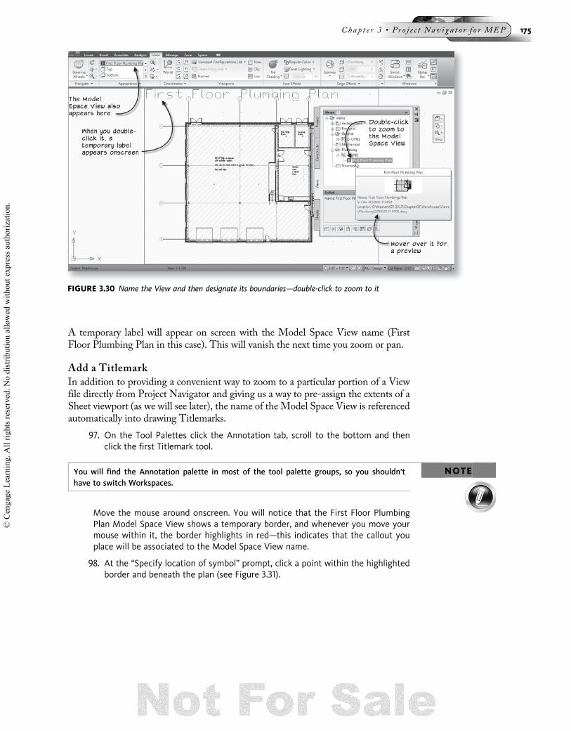
A temporary label will appear on screen with the Model Space View name (FirstFloor Plumbing Plan in this case). This will vanish the next time you zoom or pan.
Add a Titlemark
In addition to providing a convenient way to zoom to a particular portion of a Viewfile directly from Project Navigator and giving us a way to pre-assign the extents of aSheet viewport (as we will see later), the name of the Model Space View is referencedautomatically into drawing Titlemarks.
97. On the Tool Palettes click the Annotation tab, scroll to the bottom and thenclick the first Titlemark tool.
NOTEYou will find the Annotation palette in most of the tool palette groups, so you shouldn’thave to switch Workspaces.
Move the mouse around onscreen. You will notice that the First Floor PlumbingPlan Model Space View shows a temporary border, and whenever you move yourmouse within it, the border highlights in red—this indicates that the callout youplace will be associated to the Model Space View name.
98. At the “Specify location of symbol” prompt, click a point within the highlightedborder and beneath the plan (see Figure 3.31).
FIGURE 3.30 Name the View and then designate its boundaries—double-click to zoom to it
Chap t e r 3 • Pr o j e c t Nav i g a t o r f o r MEP 175
© C
enga
ge L
earn
ing.
All
right
s res
erve
d. N
o di
strib
utio
n al
low
ed w
ithou
t exp
ress
aut
horiz
atio
n.

99. At the “Specify endpoint of line” prompt, drag to the right and click to designatethe length of the title bar.
Notice that the label of the Title Bar has automatically picked up the name of theModel Space View. There is gray shading surrounding this label. This indicates thatthis is a field code. Field codes can be added to any piece of text including withinBlock Attributes (as is the case here) and then set to reference data from some otherlocation. In this case, the field is configured to read the name of the Model SpaceView in which it is contained. Had we inserted it outside the Model Space Viewboundaries, it would have read the name of the drawing file instead. This is why itwas important to insert the Titlemark within the boundaries of the Model SpaceView. Notice that the Scale has also been inserted as a field code and correctly readsthe values we assigned earlier.
Finally, there is a third field code within this Titlemark: the number within the roundbubble. Currently it is displaying a question mark (?). This is because it is tied to theactual drawing number for this plan from the Sheet. Since we have not yet built theSheet, the field cannot yet display the correct number. Later when we build ourSheets, this question mark will automatically be replaced with the correct designation(see Figure 3.32).
FIGURE 3.31 Add a Titlemark beneath the Plan, within the First Floor Plan Model Space Viewboundary
FIGURE 3.32 The Titlemark contains field codes that reference the drawing name and scale
176 The Aub in A c ad emy Ma s t e r S e r i e s : Au t oCAD MEP 2011
© C
enga
ge L
earn
ing.
All
right
s res
erve
d. N
o di
strib
utio
n al
low
ed w
ithou
t exp
ress
aut
horiz
atio
n.

100. When you are satisfied that the file has been created correctly, save and closethe file.
You have now seen some of the features and potential benefits of creating floor planViews. Below, in the “Create Sheets” topic, we will drag this View to a Sheet. Afteryou have completed that and the other exercises in this chapter, please refer back tothe “Understanding Floor Plan Views” topic above and consider the various ap-proaches to dealing with floor plans before making a final decision on the approachyou will take in your own projects.
Creating Section Views
AMEP provides several tools to view and document building sections. We can cut a“live section” view through the model that crops away the portion behind the Sectionline and reveals the sectioned portion in a live view. Depending on how these are cutand configured, live sections can even be printed under certain circumstances, but arereally intended for coordination purposes and design review.
For most design development and construction document needs, the AMEP 2DSection/Elevation object gives us the required level of control by creating a separatetwo-dimensional drawing that remains linked to the original building model and canbe updated when the original changes. To get just the right section requires a bit ofcareful configuration. (In Chapter 14, we will explore the 2D Section/Elevation ob-ject in detail.) In the “Add a Callout” topic in Chapter 14, detailed steps are given tocreate a section line, callout and associated section View file. For this reason, and dueto the similarities to the steps already presented here, we will not outline the stepshere. Please refer to that lesson and chapter if you wish to cut a section now.
Create Sheets
Sheet files are the final file type required in a Project Navigator project. The purposeof Sheet files is for printing documents. The Sheet file will have a titleblock borderand one or more viewports. These viewports will display XREFed View or Constructfiles. In this exercise, we will create a Sheet file for our project.
Create a Plan Sheet File
Let’s continue with our First Floor Plumbing Plan.
101. On the Project Navigator palette, click the Sheets tab.
Be sure that the Sheet Set view is active. If it isn’t, click the Sheet Set icon at thetop-right corner of the Sheets tab. If Sheet Set View is active, but only Ware-house shows in the list, click the plus (þ) sign icon to expand (see Figure 3.33).
Chap t e r 3 • Pr o j e c t Nav i g a t o r f o r MEP 177
© C
enga
ge L
earn
ing.
All
right
s res
erve
d. N
o di
strib
utio
n al
low
ed w
ithou
t exp
ress
aut
horiz
atio
n.

102. Select the Plumbing Subset.
103. At the base of the palette, click the Add Sheet icon.
104. For the Number, type P-101 and for the Sheet Title, type Plumbing Plan.
Notice that the File Name is created automatically by concatenating these two fields.Also, since we are using the project number prefix option, the project number is alsoadded automatically to the beginning of the file name. You can edit the File namefield manually before clicking OK, but it is recommended that you accept the defaultnaming behavior. Even though it may not match precisely the way you name Sheetfiles today, it is a logical system and happens automatically, making it much easier toensure consistency from drawing to drawing and project to project.
105. Check the “Open in drawing editor” checkbox and then click OK (see Figure 3.34).
FIGURE 3.33 Be sure the Sheet Set view is active
178 The Aub in A c ad emy Ma s t e r S e r i e s : Au t oCAD MEP 2011
© C
enga
ge L
earn
ing.
All
right
s res
erve
d. N
o di
strib
utio
n al
low
ed w
ithou
t exp
ress
aut
horiz
atio
n.

TIPWhen you rename a Sheet file, you can choose whether the associated drawing file renamesas well. When you do this, you will have the option to use the Name only, or the Name andNumber in the new file name. To see these options, select a Sheet, right-click and chooseRename and Renumber.
Like other kinds of files in Project Navigator, there is also a checkbox here to open thedrawing in the editor after creation.
106. Zoom in on the titleblock and examine the fields. Notice that many of themhave filled in automatically with project data field codes.
MANAGERNOTE
You will notice that the template used for Sheets is different from the one used by theother file types. When you first set up a project, there are settings for this. You can assignthe template used directly to the Sheet Set, or each individual Subset can have its owntemplate—this can be very useful in multi-discipline firms. We are using the defaults herewhich loads the AECB Sheet (Imperial ctb).dwt template file to create Sheets. You canchange these settings using the Edit Project icon on the Project tab and by right-clickingon the Sheet Set.
107. Zoom out to see the whole sheet.
108. On the Project Navigator palette, click the Views tab.
109. From the Plumbing folder, drag and drop the P-FP01 View from the Project Nav-igator palette directly onto the Sheet Layout (see Figure 3.35).
FIGURE 3.34 Create a new Sheet for the Plumbing Plan
Chap t e r 3 • Pr o j e c t Nav i g a t o r f o r MEP 179
© C
enga
ge L
earn
ing.
All
right
s res
erve
d. N
o di
strib
utio
n al
low
ed w
ithou
t exp
ress
aut
horiz
atio
n.

The image of the file will appear onscreen with the lower left corner attached tothe cursor.
110. Move the Viewport to position the Plan to an optimal position onscreen.
You may need to fine tune the position or size of the Viewport after placement.You can move it around and resize it with the grips.
Dragging the View onto the Sheet in this way has created a single Viewport scaled at1/8 00 ¼ 1 0-0 00. (We can verify the scale by selecting the Viewport object. A smallQuick Properties panel will appear showing the layer and scale of the Viewport.) No-tice that the Viewport is also locked. This prevents the viewport scale from beingchanged accidentally when someone has the Viewport active and then zooms. Noticealso that the Viewport is automatically placed on a non-plotting layer.
Notice that the bubble next to the Titlemark for the First Floor Plumbing Plan hasfilled in automatically with the number 1. This is because this is the first drawing onthis Sheet. If you drag another view onto this Sheet, it will become number 2, and soon (see Figure 3.36).
Take a look at the Sheet Set in Project Navigator. Notice that there is now a Viewindented beneath the Sheet name. These are more AutoCAD Named Views. (Wehave been calling them Model Space Views till now; however, that name is not
FIGURE 3.35 Drag the Plumbing Plan from the Project Navigator onto the drawing Sheet
FIGURE 3.36 A locked, properly scaled and non-plotting viewport is created—the Titlemark calloutupdates as well
180 The Aub in A c ad emy Ma s t e r S e r i e s : Au t oCAD MEP 2011
© C
enga
ge L
earn
ing.
All
right
s res
erve
d. N
o di
strib
utio
n al
low
ed w
ithou
t exp
ress
aut
horiz
atio
n.

applicable in Paper Space Layouts.) These Named Views represent the area of theSheet that is associated to a particular number. Try double-clicking on the View. Itwill simply zoom to that location on the Sheet.
111. Save and close the P-101 Plumbing Plan Sheet.
MANAGERNOTE
Although your office standards may vary considerably from the file naming and XREF struc-ture presented here, the more important issue is the strategy of using consistent file nam-ing and XREF structures from one project to the next. It is also critical to set up the projectfiles as early in the project life cycle as possible. Building the set early allows for easiersetup and maintenance, and allows the project team members to follow an establishedstandard.
Adding Constructs to Sheets
When you drag Views to Sheets, several steps are performed for you automatically.The View file (and its nested XREFs) is XREFed to model space at the correct co-ordinates. Thus, the XREF created is placed on its own layer (this facilitates viewportlayer freezing). A viewport is created in paper space at the correct scale, locked andplaced on a non-plotting layer. If they exist, callouts are updated throughout the proj-ect. Not bad for a simple drag and drop.
If you have chosen to forego Plan View files, you will need to XREF your Constructsdirectly to your plan Sheet files. Unfortunately this will take a few more steps than thesimple drag-and-drop process outlined in the last sequence. However, it is still a littleeasier to perform the required steps using Project Navigator than it would be follow-ing the traditional manual AutoCAD procedures.
Here is a simple summary of the process. You will create the Sheet using the samesteps as those covered above. Instead of dragging and dropping the Construct directlyonto the Sheet (in paper space) as you were able to do with the View file, you will firstneed to switch to model space in the Sheet file. You can drag and drop the Constructfrom Project Navigator to model space. It will XREF the file as an attachment to thecorrect X and Y coordinates. You will need to adjust the Z coordinate manually ifnecessary. You will also need to place the XREF on its own layer manually if desired.Return to paper space, create a viewport, zoom and scale it to the inserted XREF.Adjust any layer settings and lock the viewport.
Making Sheets Match Architectural Sheets
When you receive the background files in Project Navigator as we have been discuss-ing in this scenario, it is likely that the Architect has also configured Sheets of theirown. If they have sent you these Sheets, you can save some work in configuring yourown Sheets by “borrowing” their viewports. To do this, open the Architectural Sheetyou wish to mimic. In paper space, select all the viewports (you can select one, right-click and choose Select Similar). On the Home tab of the ribbon, expand theModifypanel and choose Copy with Base Point from the Copy to Clipboard drop-down but-ton. Type 0,0 for the base point and then press ENTER. Create your Sheet using theprocedures covered here. Expand the Modify panel again, and choose the Paste toOriginal Coordinates tool. (If this does not place them correctly, try Paste and thentype 0,0 again.) Switch to model space and perform the procedures to XREF the re-quired Constructs into the file as noted in the previous topic.
Chap t e r 3 • Pr o j e c t Nav i g a t o r f o r MEP 181
© C
enga
ge L
earn
ing.
All
right
s res
erve
d. N
o di
strib
utio
n al
low
ed w
ithou
t exp
ress
aut
horiz
atio
n.

Updates
When the Architect sends you updated files, you can simply overwrite the previousversions of the project files with the new ones they send. Naturally you will want tobackup the project directory before overwriting any files. Make sure that the Architecthas not sent you copies of your own files before doing this. Communication with theArchitect and running a few tests will ensure seamless updates and prevent loss ofwork. Remember to backup often!
If your Architect is not using relative paths as outlined above in the “UnderstandingRepath Options” topic, encourage them to do so. It will make updates much easier asyou will not have to mimic the Architect’s drive letters and folder structure. If theyinsist on absolute paths, your next best option is to create a custom drive mappingthat mimics the Architect’s drive and folder structure.
112. Close the current project and, when prompted, close (and save) all project files.
Engineer Is Using Project Navigator, Architect Is NotOur third sub-scenario: The first option under Scenario 2 occurs when you have de-cided to use Project Navigator, but your Architect has not. This would apply if theyare using plain AutoCAD or some other CAD program.
The only major difference in this scenario from the other two covered so far is thatyou will have to create the project yourself. The basic process involves creating theproject, setting up the Levels and Divisions (if being used), adding folders and thenadding files. Since we have already covered how to add files (Constructs, Elements,Views and Sheets) we will focus on the initial setup tasks in this topic.
Create a New Project
1. On the QAT, click the Project Browser icon.
Browse to the location (usually on the project server) where you want to save the proj-ect. This is the location from which all team members will access it. For this example,we’ll continue to work in the Chapter03 folder.
2. With the Chapter03 folder showing in the drop-down list, click the New Projecticon (see item j in Figure 3.1 above) at the bottom of the “Project Browser”dialog.
NOTE Be sure to browse to the folder first, then click the New Project icon. Review items cthrough h in Figure 3.1 above for the tools used to navigate within Project Browser.
The Add Project worksheet will appear.
3. In the Project Number field, type 2011.03.
4. In the Project Name field, type Chapter 3.
5. For the Project Description type Mastering AutoCAD MEP 2011.
6. Clear the “Create from template project” checkbox (see Figure 3.37).
182 The Aub in A c ad emy Ma s t e r S e r i e s : Au t oCAD MEP 2011
© C
enga
ge L
earn
ing.
All
right
s res
erve
d. N
o di
strib
utio
n al
low
ed w
ithou
t exp
ress
aut
horiz
atio
n.

7. Click OK to create the project.
In this example, we are creating the project from scratch (we have cleared the tem-plate project checkbox). However, you have the option to create projects from a tem-plate project. A template project is much like a drawing template (DWT): It providesa pre-configured starting point for a new project that can potentially include settings,drawing template file references, tool palettes and even premade drawing files. Thereare no good MEP samples provided with the software. There is an architectural ex-ample named Commercial Template Project that provides a good example of the poten-tial of template projects. It includes pre-configured levels and a collection of premadeConstructs, Views and Sheets and other settings as well. You can also find a detaileddescription of the Commercial Template Project in the help file.
• The new Chapter 3 Project will appear in the Project Browser (highlighted inbold to indicate that it is current).
MANAGERNOTE
The bulletin board and image in this project are blank. Any HTM or HTML file can be used asa project bulletin board. You can use virtually any word processor, text editor, or HTML edi-tor to create or edit project bulletin board files. A project bulletin board can be used by aProject Coordinator or CAD Manager to keep project team members informed on projectnews, or as a way to provide links to project standards, project tools or links to relatedWeb sites and resources. The Project Web page displays in its own integrated Web Browserwindow within the Project Browser, complete with its own Back, Forward, Home and Re-fresh icons (see item i and item l in Figure 3.1 above). In this way, the project Bulletin Boardcan actually reference a home page to an entire intranet project Web site. If you prefer notto use the Bulletin Board feature in projects, simply leave it blank.
The Project Image file is a logo for the project. Any image file can be used for this image,but it must be saved in BMP format. Use Photoshop, Windows Paint or any other image ed-itor to save the image file. If your project has its own logo, you can load it here. Otherwise,you can use your company logo, the client’s logo, or you can leave it blank.
8. Right-click on the Chapter 3 project in Project Browser and choose ProjectProperties (see Figure 3.38).
FIGURE 3.37 Input the name, number and description of the new project
Chap t e r 3 • Pr o j e c t Nav i g a t o r f o r MEP 183
© C
enga
ge L
earn
ing.
All
right
s res
erve
d. N
o di
strib
utio
n al
low
ed w
ithou
t exp
ress
aut
horiz
atio
n.

We have already discussed the settings in this dialog above. Make the followingchanges:
9. For “Use Relative Xref Paths,” choose Yes.
10. For “Match Sheet View Layers to View,” choose Yes.
11. For “Prefix Filenames with Project Number,” choose Yes (see Figure 3.38).
When you create a new project, a Tool Palette Group (refer to Chapter 1) can option-ally be associated with the project. If you have Tool Palettes within this group, theywill automatically load in project team members’ workspaces. We will not useProject-based Tool Palette Groups in this book. Therefore, let’s turn this off.
12. In the “Project Properties” dialog, scroll to the bottom and locate the Tool Pal-ettes item.
13. For “Project Tool Palette Group” choose: None and then click OK.
14. If any warnings regarding the bulletin board and project image appear, simplyclose them.
15. In the confirmation dialog regarding repathing the project, choose Yes.
16. Click Close to close the Project Browser and return to AMEP.
The Project Navigator palette will appear onscreen with the new project loaded.
TIP You can also load your project directly from Windows Explorer before even launchingAMEP. Simply browse to the directory where the AMEP project is found and double-clickon the APJ file located directly in the project’s folder. AMEP will launch a new session andmake the selected project current. If AMEP is already running, launching a project throughWindows Explorer will open a second session.
Set Up Project Levels
The first thing we need to set up in our new project is the Levels.
17. On the Project tab, click the Edit Levels icon (see Figure 3.39).
FIGURE 3.38 The Project Browser—editing properties of the newly created project
184 The Aub in A c ad emy Ma s t e r S e r i e s : Au t oCAD MEP 2011
© C
enga
ge L
earn
ing.
All
right
s res
erve
d. N
o di
strib
utio
n al
low
ed w
ithou
t exp
ress
aut
horiz
atio
n.

Let’s create a simple three-storey building. We will need a Level for each. We alsotypically want to add a Level for the site conditions and the roof. This will give ournew project five Levels.
The default Level is named “1.”
18. Click in the Floor Elevation column and edit the value to 1 0-0 00.19. Change the Floor to Floor Height to 12 0-0 00.20. Change the Description to read First Floor (see Figure 3.40).
21. At the top right corner, click the Add Level icon three times.
Notice that the new Levels have automatically been named sequentially, and theFloor Elevations begin at height of the Level below. This is due to the “Auto-Adjust Elevation” setting, which is on by default (see the bottom left corner ofFigure 3.40).
FIGURE 3.39 Edit the Levels from the Project tab on the Project Navigator
FIGURE 3.40 Edit the parameters of the First Floor Level
Chap t e r 3 • Pr o j e c t Nav i g a t o r f o r MEP 185
© C
enga
ge L
earn
ing.
All
right
s res
erve
d. N
o di
strib
utio
n al
low
ed w
ithou
t exp
ress
aut
horiz
atio
n.

22. Edit the Descriptions to read: Second Floor, Third Floor and Roof.
23. Rename Level 4 to R and change its ID as well (see the left side of Figure 3.41).
24. In the Name column, select 1, right-click, and choose Add Level Below (see theright side of Figure 3.41).
A Level is added below the current level; it is named “5.” This name and theFloor Elevation of this Level require adjustment.
25. Click in the Name column (on the number “5”), pause a moment, and then clickagain.
This should activate the rename mode for Level 5. You can also right-click andchoose Rename Level.
26. Change the Name to G.
27. Click in the Floor Elevation column and edit the value to 0.
This will distort all the other Floor Elevation values. Don’t worry—with Auto-Adjust on, it is easy to fix.
28. Change the Floor to Floor Height to 1 0-0 00.29. Change the ID to G (for “Grade“) and the Description to Grade Level (see
Figure 3.42).
30. Click OK to accept the values and dismiss the Levels dialog.
31. A prompt will appear asking you to “Update all Project Views.” Click the Yesbutton (see Figure 3.43).
FIGURE 3.41 Add and edit several Levels
FIGURE 3.42 Completing the edits to the Project Level Structure
186 The Aub in A c ad emy Ma s t e r S e r i e s : Au t oCAD MEP 2011
© C
enga
ge L
earn
ing.
All
right
s res
erve
d. N
o di
strib
utio
n al
low
ed w
ithou
t exp
ress
aut
horiz
atio
n.

Answering “Yes” to this prompt will update all drawings that reference the ProjectLevels to incorporate the new values just entered. There are not any drawings in thisproject that would require such updating, but you should typically answer “Yes” tothis prompt regardless. This will ensure the integrity of your project files and theirrelationships to one another.
Let’s assume that the project we are configuring is large enough to warrant more thanone Division. Divisions break the project into sections. You can use them as a way tosplit the work on a single Level between two or more individuals. Most projects willnot use Divisions, but in case you have one that justifies their use, let’s walk throughthe steps here.
32. On the Project tab, click the Edit Divisions icon
33. In the “Divisions” dialog, make the edits shown in Figure 3.44.
34. Click OK to complete the Divisions.
At this point, we have completed the general project parameters and established thatthe building will be divided into five Levels (including the Grade and Roof Levels)and two Divisions. Keep in mind that we can revise this structure later if necessaryand adjust the Level and Division structure as changing project needs dictate. Natu-rally, we would want to try to avoid drastic changes to the Level and Division struc-ture wherever possible. The important point to note here is that this structure can beadjusted later if required.
The next step is to build the files called Constructs and Elements that will populatethis building framework. These will be comprised of drawing files that represent var-ious portions of the building information model as defined in the next topic.
FIGURE 3.43 Completing the edits to the Project Level Structure
FIGURE 3.44 The Project Navigator complete with Divisions and Levels
Chap t e r 3 • Pr o j e c t Nav i g a t o r f o r MEP 187
© C
enga
ge L
earn
ing.
All
right
s res
erve
d. N
o di
strib
utio
n al
low
ed w
ithou
t exp
ress
aut
horiz
atio
n.

Import Architectural Background Files
In this scenario, we are receiving basic AutoCAD background files from our Archi-tect. These are not Project Navigator files and in fact are simple 2D line drawings thatdo not use AEC objects at all. You can XREF the files directly into your files, but youmight want to consider creating a “buffer” file first. When you get files from an out-side source, you have no control over the contents or quality. Furthermore, even if youspend time to “cleanup” a received file, you will lose the benefits of your efforts thenext time the Architect sends an update. Therefore, consider creating an empty fileusing your office standard template (DWT) file first. XREF the Architect’s back-ground into this file. Make any modifications to layers and other settings in thishost file. You will be modifying the XREF layers, but the settings will be saved andmaintained with the host file. You can even move or rotate the XREF if necessary,and those transformations will be saved with the file as well. When the Architectsends their update, overwrite their original file and then reload your XREFs. All ofyour cleanup settings will be preserved! The Elements folder in Project Navigator pro-vides an excellent staging area for such procedures.
35. On the Project Navigator palette, click the Constructs tab.
36. Right-click the Elements folder and choose New . Category.
37. Name the new folder: Architectural Backgrounds.
You can save each file individually to the Elements folder by opening them inAMEP, right-click the Architectural Backgrounds folder and choose Save CurrentDwg as Element. Confirm the name in the dialog that appears and then click OK.This is fine if you have only a few drawings to process. However, if there are many,you might want to try this alternative:
38. Open a Windows Explorer window and browse to the location of the files youreceived from the Architect.
You will have to unzip the files to a folder on your system first. This location willmost likely be a folder in the project directory on the server. Check with yourproject data coordinator to be sure.
39. Select all of the files, drag them from Explorer and drop them on the Architec-tural Backgrounds folder directly in Project Navigator (see Figure 3.45).
FIGURE 3.45 Drag the Architectural backgrounds from Windows Explorer to Project Navigator
188 The Aub in A c ad emy Ma s t e r S e r i e s : Au t oCAD MEP 2011
© C
enga
ge L
earn
ing.
All
right
s res
erve
d. N
o di
strib
utio
n al
low
ed w
ithou
t exp
ress
aut
horiz
atio
n.

An “Add Element” dialog will appear for each file dragged and dropped.
40. Simply click OK in each dialog to confirm them (see Figure 3.46).
You now have a list of Element files matching the names of the files you receivedfrom the Architect. These are copies of the files you received saved in the Architec-tural Backgrounds folder. In addition, each one now has an accompanying XML filelike the other project files as discussed earlier in this chapter. Our next step is to createa Construct for our Architectural files. You have a few options here. You can create aConstruct for each file, or create a single Construct per floor Level. For example, ifthe Architect sent a core and shell file, an interior walls file, and a column grid file foreach floor, you may want to merge all three of these into a single Construct. Simplycreate a Construct per Level and then drag and drop in the appropriate Element files.
41. On the Construct tab, right-click the Constructs folder and choose New .Category.
42. Name the new Category: Architectural.
43. Right-click the Architectural folder and choose New . Construct.
If you wish, add a Description.
44. In the “Add Construct” dialog, name the file according to your standards, per-haps: 01 Architecture.
45. If you created Divisions above, check both North and South for Level 1, check“Open in drawing editor” and then click OK (see Figure 3.47).
FIGURE 3.46 Confirm the importing of each Architectural file as an Element
FIGURE 3.47 Confirm the importing of each Architectural file as an Element
Chap t e r 3 • Pr o j e c t Nav i g a t o r f o r MEP 189
© C
enga
ge L
earn
ing.
All
right
s res
erve
d. N
o di
strib
utio
n al
low
ed w
ithou
t exp
ress
aut
horiz
atio
n.

46. From the Elements\Architectural Backgrounds folder, drag and drop the ColumnGrid file and then repeat for the Architecture file.
47. Make any layer adjustments necessary and then save and close the file.
When your Architect sends an update, simply browse in Windows Explorer to theElements\Architectural Backgrounds folder and copy the new versions over the origi-nals. Only the DWG files will be replaced; the XML files will be unaffected. Thenext time you open your 01 Architecture Construct or update its XREFs, it will showthe latest changes.
Creating Files
The rest of the procedure is the same as the steps covered above in the “Createfolders,” “Create Constructs,” “Create Views” and “Create Sheets” topics. Create afolder for each discipline in the Constructs and Views folders. Create Subsets on theSheet tab. Add all the Constructs, Views and Sheets that your project requires.
Save everything and make a backup of the project when your setup is complete.
Template Projects
Template Projects have already been noted above. If you find that you are performingmany of the same setup tasks over and over on each new project, it is time to considercreating a Template Project. Any project can become a Template Project. Simply setup a project that adheres as closely as possible to your office standards, and then copyit to the server to a convenient location. The next time you create a project, check the“Create from template project” checkbox in the “Add Project” dialog (see Figure 3.37above). Browse to the Template Project and AMEP will copy the Template Projectto the location of the new project, rename it, and repath all XREFs. Your new projectwill begin where the template left off.
CONGRATULATIONS!You have discovered many of the benefits of working in the Project Navigator envi-ronment. While the workflow may be different than you are used to today, you areencouraged to spend the time required to get comfortable with this powerful tooland all its features. Once you start reaping the benefits of a well structured ProjectNavigator project, you will wonder how you ever got by without it.
SUMMARY
• Thorough project setup can help give a good sense of project drawing require-ments early in the project cycle.
• Using the Project Browser and Project Navigator tools makes setting up a proj-ect quick and easy.
• AMEP Drawing Management tools make use of XREFs to relate files to oneanother.
• XREF Overlay is used when you want the XREF to go only one level deep.
• XREF Attach creates nested references, which create a hierarchical referencestructure.
• Model files are full-scale drawings used to generate actual project data on a dailybasis.
190 The Aub in A c ad emy Ma s t e r S e r i e s : Au t oCAD MEP 2011
© C
enga
ge L
earn
ing.
All
right
s res
erve
d. N
o di
strib
utio
n al
low
ed w
ithou
t exp
ress
aut
horiz
atio
n.

• Constructs and Elements are Model files representing individual pieces of a com-plete building model.
• Constructs have a unique physical location within the Building Model; Elementsdo not.
• Views are used to gather a collection of Constructs (and any nested Elementsthat they may contain) for a specific viewing purpose.
• Sheet files are used for setting up “ready to plot” sheets for printing documentsets.
• There are two overall project startup scenarios each with two sub-scenarios.
• Scenario 1—Project Navigator is already set up. This occurs either with an in-house Architectural department, if you are part of an AE firm, or when youroutside Architect sends you Project Navigator files.
• Scenario 2—Project Navigator is not set up. Here you can still set up ProjectNavigator yourself for your engineering work on the project.
• Each scenario has its own unique setup issues and plenty of areas of overlap withthe other scenarios. Become familiar with all tools, techniques and options avail-able in Project Navigator to get the most out of the tool.
Chap t e r 3 • Pr o j e c t Nav i g a t o r f o r MEP 191
© C
enga
ge L
earn
ing.
All
right
s res
erve
d. N
o di
strib
utio
n al
low
ed w
ithou
t exp
ress
aut
horiz
atio
n.

© C
enga
ge L
earn
ing.
All
right
s res
erve
d. N
o di
strib
utio
n al
low
ed w
ithou
t exp
ress
aut
horiz
atio
n.