Embed Size (px)
Citation preview
Technical specification for 3840kW Voith tug
1
3840kW Voith Tug
Technical Specification
Contents
Technical specification for 3840kW Voith tug
2
Part 1 General Provisions..........................................................................................................4 1.01 General...................................................................................................................4 1.02 Working environment.............................................................................................5 1.03 Particulars of the ship...........................................................................................5 1.04 Performance and operational region ......................................................................6 1.05 Rules and regulations .............................................................................................7 1.06 Language and unit of measure ...............................................................................7 1.07 Classification, registry and notations .....................................................................8 1.08 Name plates and markings .....................................................................................8 1.09 Design requirements ..............................................................................................8 1.10 Construciton and supervision.................................................................................9 1.11 Launch...............................................................................................................10 1.12 Tests and trials......................................................................................................10 1.13 Delivery................................................................................................................ 11 1.14 Quality assurance and after-sale service ..............................................................12
Part 2 Hull ..........................................................................................................................13 2.01 General.................................................................................................................13 2.02 Main hull material and steel treatment.................................................................13 2.03 Hull structure .......................................................................................................13 2.04 Welding ................................................................................................................14 2.05 Liquid tanks .........................................................................................................14 2.06 Main structure ......................................................................................................14 2.07 Mast and funnel....................................................................................................17 2.08 Doors, windows, ladders, handrails and railings..................................................18 2.09 Hull painting ........................................................................................................19 2.10 Hull protection .....................................................................................................19
Part 3 Deck machinery............................................................................................................21 3.01 Windlass...............................................................................................................21 3.02 Winch...................................................................................................................21 3.03 Hydraulic system for deck machinery..................................................................22 3.04 Hawser ropes........................................................................................................22
Part 4 Cabin arrangement........................................................................................................23 4.01 General....................................................................................................................23 4.02 Cabin devices ..........................................................................................................23 4.03 Air conditioner .....................................................................................................27 4.04 Domestic hot water system .....................................................................................27
Part 5 Outfitting ......................................................................................................................28 5.01 General....................................................................................................................28 5.02 Wooden outfitting....................................................................................................28
Part 6 Fire fighting and life saving appliances.....................................................................30 6.01 General....................................................................................................................30 6.02 Life apparatus..........................................................................................................30 6.03 Inboard fire fighting................................................................................................30 6.04 External fire fighting system................................................................................32
删除的内容: 3
删除的内容: 3
删除的内容: 4
删除的内容: 4
删除的内容: 5
删除的内容: 6
删除的内容: 6
删除的内容: 7
删除的内容: 7
删除的内容: 7
删除的内容: 8
删除的内容: 9
删除的内容: 9
删除的内容: 10
删除的内容: 11
删除的内容: 12
删除的内容: 12
删除的内容: 12
删除的内容: 12
删除的内容: 13
删除的内容: 13
删除的内容: 13
删除的内容: 16
删除的内容: 17
删除的内容: 18
删除的内容: 18
删除的内容: 20
删除的内容: 20
删除的内容: 20
删除的内容: 21
删除的内容: 21
删除的内容: 22
删除的内容: 22
删除的内容: 22
删除的内容: 26
删除的内容: 26
删除的内容: 27
删除的内容: 27
删除的内容: 27
删除的内容: 29
删除的内容: 29
Technical specification for 3840kW Voith tug
3
Part 7 Navigation and communication equipment ..................................................................34 7.01 Navigation lights and signal lights..........................................................................34 7.02 Telecommunication equipment ............................................................................35 7.03 Navigation equipment .............................................................................................38
Part 8 Main Engine Room Equipment ....................................................................................40 8.01 General....................................................................................................................40 8.02 Main engine ............................................................................................................41 8.03 Propulsor .................................................................................................................43 8.04 Diesel generator set .................................................................................................43
Part 9 Piping and ship system.................................................................................................45 9.01 General................................................................................................................45 9.02 Materials and construction requirements of the piping........................................45 9.03 Ship system..........................................................................................................48 9.04 Tools and storeroom of the engine room..............................................................53
Part 10 Monitoring and Alarm System ...................................................................................54 10.01 General..................................................................................................................54 10.02 Wheelhouse console..............................................................................................54 10.03 Alarm ....................................................................................................................55
Part 11 Electric equipment ......................................................................................................58 11.01General ...................................................................................................................58 11.02 Cables....................................................................................................................59 11.03 Generator...............................................................................................................60 11.04 Transformer ...........................................................................................................60 11.05 Storage batteries and charging devices..................................................................61 11.06 Electric distribution and monitoring equipment....................................................61 11.07 Power equipment...................................................................................................63 11.08 Lighting system.....................................................................................................64
Part 12 Annex..........................................................................................................................66 Annex 1: Import equipments list supplied by ship owners .............................................66 Annex 2: List of daily necessities ...................................................................................67 Annex 3: Tool list for hull ...............................................................................................68 Annex 4: Tools list for marine machineries ....................................................................70 Annex 5: Supplies list of hull..........................................................................................75 Annex 6: Tools list for marine machineries ....................................................................76 Annex 7: Electrical spare parts and tools list ..................................................................77
删除的内容: 33
删除的内容: 33
删除的内容: 34
删除的内容: 37
删除的内容: 39
删除的内容: 39
删除的内容: 40
删除的内容: 42
删除的内容: 42
删除的内容: 44
删除的内容: 44
删除的内容: 44
删除的内容: 47
删除的内容: 52
删除的内容: 53
删除的内容: 53
删除的内容: 53
删除的内容: 54
删除的内容: 57
删除的内容: 57
删除的内容: 58
删除的内容: 59
删除的内容: 59
删除的内容: 60
删除的内容: 60
删除的内容: 62
删除的内容: 63
删除的内容: 65
删除的内容: 65
删除的内容: 66
删除的内容: 67
删除的内容: 69
删除的内容: 74
删除的内容: 75
删除的内容: 76
Technical specification for 3840kW Voith tug
4
Part 1 General Provisions
1.01 General
This technical specification is to be a directive document for the construction of two (2) Voith
tugs driven by 3840kW main engine and with a propulsion plant of Voith-Schneider (hereinafter
referred to as “the ship”).
The design, construction of the ship is to be in compliance with the rules and regulations of
China Classification Society(CCS)for the tug engaging in the coastal towing and offshore
navigation and also, in accordance with this technical specification and the General Arrangement
Plan (Drawing No:VFX632-100-03).
The ship is to be used in Yangshan Port as an aid and escorting vessel during the berthing and
mooring operation of large ships. It shall feature external firefighting function, powerful towing
and pushing capability, good stability, maneuverability and safety.
The ship is to be designed and constructed to meet the requirement that the harbor operation
should be carried out by a complement of four (4) persons at a minimum.
The material and equipment to be used in the construction of the ship shall be completely
new, in compliance with the requirement of CCS and provided with conformity certificates. The
propulsion plant, main engine, deck machinery and external firefighting equipment of the ship
shall be imported and supplied by the Buyer (refer to List of Buyer-supplied Items in Part 6).
When such equipment arrives and clears in, the Seller shall be fully responsible for the receiving,
transportation, warehousing, unpacking and inspection, installation, testing and commissioning. In
case any technical or quality problems occurred the Seller shall be responsible for contacting with
the equipment suppliers to solve such problems and signing necessary documents concerned.
The Seller shall bear solely all the responsibilities to the whole design, construction,
workmanship and quality and shall not diminish its responsibility to possible loss (including
possible delayed delivery) caused by its negligence on the reason that the drawings have been
approved by the Buyer.
Necessary allocations not specified in this specification but required by the rules and
regulations and/or by maritime authorities as listed in Section 1.05 shall be provided by the Seller
and on the Seller’s expenses.
Technical specification for 3840kW Voith tug
5
1.02 Working environment
All machines and equipment of the ship shall be working normally under the temperature and
conditions as follows:
Ambient temperature: 45oC
Sea water temperature : 32oC
Atmospheric pressure, absolute: 0.1MPa
Relative humidity: 60%
1.03 Particulars of the ship
Particulars:
Length overall about 30.20m
Length of waterline 28.00m
Breadth, molded 11.20m
Depth, molded 4.20m
Draught, light weight about 2.80m
Draught, maximum about 5.00m
Displacement, full loaded about 600t
Speed ≥12.5 kn
Bollard pull, static ≥50.9 t
Main machinery:
Main engine
Manufacturer: YANMAR
Type: 6EY26
Power: 1920kW
Revolution: 750 rpm
Quantity: 2 units
Propulsion plant(Voith-Schneider propeller)
Manufacturer: Voith Hydro GmbH & Co.KG
Type: Voith-Schneider 28 G /210Ⅱ -2
Quantity of blade: 5
Revolution: 76 rpm
Quantity: 2 sets
Stern warping winch
Technical specification for 3840kW Voith tug
6
Manufacturer: Karmoy, Norway
Type: M361586
Hydraulic pump package: 76 kW,main engine PTO driven
Quantity: 1 unit
Generator set:
Diesel engine: Cummins, China
Generator: Siemens, Wuxi China
External firefighting
Manufacturer: Mengshun (Hong Kong) Co.
Firefighting capacity: 1500m3/h,water screen(300m3/h)
Outward fire pump: 715.3kW,main engine PTO driven
Complement:
The ship is to be designed to meet the requirement that the rest room and the berths shall be
suitable for the use of 12 crews at a minimum.
1.04 Performance and operational region
1.04.1 Speed
The sailing speed of the ship under 100% rated revolution of the main engines shall be
12.5 knots.
1.04.2 Pull
Static bollard pull:
The static bollard pull of the ship shall be 50.9t under the condition that it is in open
waters and at a speed of 0 knot while the main engine is running at the power of 100%
MCR.
Dynamic pull:
1.04.3 Operational region
The ship is to be operated in Yangshan Port and its adjacent regions.
1.04.4 Seaworthiness
The ship shall have good wave-going performance and can safely navigate at
Beauford wind scale 10. It shall be able to carry out normally the towing, pushing or
traversing operation under the condition of Beauford wind scale 9 and wave height of 3m. It
Technical specification for 3840kW Voith tug
7
shall meet the requirement that the ship can safely send or pick up a pilot under the
condition that the wave height is 4m. (The above-mentioned seaworthiness shall be
guaranteed by Vioth Company.)
1.04.5 Endurance
Endurance of the ship (at a speed of 12.0 knots) shall be equal to or more than 1200
nautical miles.
1.04.6 Vibration and noise
Vibration of the ship shall meet the requirements for the vibration of a seagoing ship
as specified in Standard GB7452-87—Evaluation Criterion for Hull Vibration.
Noise level of the ship, when it is measured according to the method specified in
Standard GB5979-86—Noise Level for Seagoing Ship, shall meet the following
requirements:
Wheelhouse ≤70 dB
Cabins and mess room ≤70 dB
Engine monitoring room ≤80 dB
1.05 Rules and regulations
The ship is to be designed and constructed in accordance with following rules and
regulations:
1) Rules and Regulations for the Construction and Classification of Steel Seagoing
Ships of China Classification Society, currently in effect (hereinafter referred to as
“Rules”)
2) Technical Regulations for Statutory Survey of Seagoing Ships Navigating in
Domestic Waters as part of the “Regulation for Survey of Ships and Offshore
Installations” (2004) of Maritime Bureau of the People’s Republic of China
(hereinafter referred to as “Regulations”)
1.06 Language and unit of measure
Technical documents in relation to the design and construction of the ship shall be written in
Chinese unless otherwise mentioned. All measuring units to be adopted shall be legal units of
measurement of the People’s Republic of China.
Technical specification for 3840kW Voith tug
8
1.07 Classification, registry and notations
1.07.1 Classification
The ship shall be classified as ★CSAD.
1.07.2 Registry
The ship shall be registered at Shanghai Port.
1.08 Name plates and markings
1.08.1 Name plates
Name plates made of brass and written in Chinese shall be provided for the cabins and
rooms, equipment, electric control cabinets and valves on board the ship.
1.08.2 Identification marks
Ship name and registry port mark shall be cut from steel plate in thickness of 6mm and
written in Chinese and Pinyin whose form and size shall be approved by the Buyer.
1.08.3 Draught mark and load-line mark
Draught mark and load line mark shall be made of steel plate in thickness of 6mm by
means of cutting to the requirement of the Regulations.
1.09 Design requirements
1.09.1 Design standard
The design of the ship shall be responsible by the Seller in accordance with this
Technical Specification, the Rules and the Regulations.
1.09.2 Drawings and technical information
1.09.2.1 Buyer’s approval of the drawings
On completion of the technical design, the Seller shall submit to the Buyer three (3)
sets of design drawings for the latter’s approval. An exchange of design intention shall be
held between both parties and the Buyer’s representative shall be invited to approve the
drawings at a place agreed by both parties. The Seller shall determine a schedule for the
drawings approval and be responsible for the arrangement and affairs of the drawings
approval meetings. The construction of the ship shall not be commenced before the
completion of the drawings approval.
1.09.2.2 CCS approval of the drawings
The design drawings approved and signed by both partied shall be submitted to CCS
for review and approval.
The Seller shall inform in time the CCS approval conclusion and comments (if any) to
the Buyer.
Technical specification for 3840kW Voith tug
9
One (1) set of the CCS approved design drawings with CCS approval stamps shall be
submitted to the Buyer.
1.09.2.3 Construction drawings
Before the commencement of the ship three (3) sets of the construction drawings shall
be submitted to the Buyer.
1.09.2.4 Finished drawings
Upon delivery of the ship, three (3) sets of the finished drawings and two copies in
compact disk form shall be furnished to the Buyer. All the drawings and lists shall be clearly
identified and in standard binding form and put in file cases with unified labeling.
1.10 Construciton and supervision
The Seller shall assume full responsibility for the construction schedule, performance and
quality of the ship, and shall not to delay the delivery in any reasons (including the Seller’s
workmanship, delayed supply of equipment and material, etc.).
Prior to the commencement of the construction, the schedule of the whole construction
project shall be submitted to the Buyer; during the construction, a monthly progress report on the
construction shall be submitted to the Buyer at the end of every month.
The Seller shall invite representative of the Buyer to supervise the construction and witness
the inspections and tests concerned. The Seller shall furnish the representative of the Buyer with
necessary facilities, tools, personal protection equipment and office appliance that are necessary
for the supervision.
All the inspection or testing items to be witnessed by the representative of the Buyer shall be
informed him/her in advance by the Seller.
The problem(s) to be raised by the representative of the Buyer in written form during the
supervision shall be replied in written by the Seller within five (5) working days.
The following major construction stages shall not be conducted or proceed until they have
been accepted and signed by the representative of the Buyer:
(1) Erection of hull blocks shall not be conducted until the blocks have been inspected,
accepted and signed;
(2) The launch of the ship shall not be conducted until the completion of hull erection has
been inspected, accepted and signed;
(3) Installation of main engine shall not be conducted until the shaft alignment has been
inspected, accepted and signed;
Technical specification for 3840kW Voith tug
10
(4) Sea trial and bollard pull test shall not be conducted until the installation and
commissioning of various parts have been completed and the mooring test has been accepted and
signed by the representative of the Buyer;
(5) Problems to be found during the acceptances of each stage and/or caused again in the
work of subsequent steps shall be solved by the Seller soonest possible and be accepted on
completion of the work in downstream stage.
(6) Prior to closing any covert or enclosed spaces/items they shall be inspected and
accepted by the representative of the Buyer. Otherwise the representative of the Buyer shall have
the right to open these spaces and have a check.
1.11 Launch
The Seller shall inform the Buyer in written form the launch date of the ship seven (7)
days in advance.
1.12 Tests and trials
1.12.1 Generals
The inclination test program, mooring test program and sea trial program must be
approved by CCS and agreed by the Buyer. Otherwise no such tests should be conducted.
The mooring test program and sea trial program shall be prepared in accordance with
General Provisions for Mooring test and Sea Trial of Sea-going Ships (GB/T3471-1995).
All statutory tests and trials shall be carried out in the presence of the surveyor of
classification society and representative of the Buyer. Otherwise the Buyer has the right to
require a re-test to what not witnessed by its representative.
1.12.2 Shop test
When the shop tests of principal equipment (main engine and Voith propeller) to be
supplied by foreign manufacturers, and of major equipment (auxiliary engine, main
switchboard) to be supplied by domestic manufacturers, the representative of the Buyer
shall be invited to attend.
1.12.3 Inclination test
The inclination test shall be conducted in accordance with the inclination test program
approved by CCS and the Buyer and the representative of the Buyer shall be informed five
(5) days in advance of the test date.
1.12.4 Mooring test
The mooring test shall be conducted in accordance with the mooring test program
approved by CCS and the Buyer and the representative of the Buyer shall be informed five
(5) days in advance of the test date.
Technical specification for 3840kW Voith tug
11
1.12.5 Sea trial
The sea trial shall not be carried out until the mooring test has been completed and the
defects found thereof have been corrected. The sea trial shall be conducted in accordance
with the sea trial program approved by CCS and the Buyer. The representative of the Buyer
shall be informed in written form seven (7) days in advance of the sea trial date.
1.12.6 Bollard pull test
The bollard pull test shall be conducted at the rated revolution of the main engine. The
representative of the Buyer shall be informed in written form seven (7) days in advance of
the test date.
1.12.7 Test of external firefighting facilities
The test of external firefighting facilities shall be conducted in accordance with the
test program approved by CCS and the Buyer. The representative of the Buyer shall be
informed in written form fifteen (15) days in advance of the test date.
1.13 Delivery
The ship shall be delivered at the wharf specified by the Buyer. Before the delivery of the
ship various tests and trials should have been completed and the performances met the
requirements of the Technical Specification. All the spare parts, tools and accessories (to be
furnished according as per Annex2~Annex7 of this Technical Specification), certificates,
documents have been available. When delivery the ship shall be thoroughly cleaned and without
sewage and dirty water in tanks, cabins, rooms and outside walls shall be free from construction
defects, mechanical and electrical equipment shall be in good conditions, and all the machines,
equipment, pipelines and tanks shall be clean and rustproof.
When delivery following certificates and documents shall be provided:
(1) Certificate Book for the Survey of Ship, one origin copy and one duplicate copy;
(2) Tonnage certificate and Load line certificate;
(3) Oil pollution prevention certificate;
(4) Marine equipment and products certificates issued by CCS;
(5) Compass deviation table;
(6) Builder’s quality certificate;
(7) Ship property rights hand over certificate;
(8) Service and operational instructions, spare part lists of all the equipment and finished
drawings and documents.
Following drawings shall be furnished in wooden frames and placed on board the ship at
Technical specification for 3840kW Voith tug
12
proper locations:
(1) General Arrangement;
(2) Life-saving Equipment Arrangement;
(3) Fire Control Plan (with CCS stamp).
A complete set of color photos, which show comprehensively and systematically the
whole process of the construction from the keel lay-down to the delivery of the ship, shall be
furnished in batches to the Buyer. Four (4) photos, to be taken on completion of the ship when
there is no man on the deck to show its best appearance, shall be furnished to the Buyer in wooden
frames, whose width should not be less than 0.5m.
1.14 Quality assurance and after-sale service
During the construction of the ship the inspection department of the Seller shall carry
out inspection and testing according to this Technical Specification, the Rules, the Regulations,
and the standard of the shipyard and report in time the inspection results to the representative of
the Buyer who is stationed in the shipyard.
Guarantee period of the ship shall be one (1) year counting from the date of delivery. During
the guarantee period in case it is found that system damage or equipment failures are caused by
the design or construction, the Seller shall dispatch service engineer(s) to the spot within seven (7)
days to shoot the trouble and repair at its own expenses. Should the Seller fail to provide service in
time when the ship or equipment is in failure, the Buyer shall have the right to handle the repair to
ensure safe operation of the ship, and the repair expenses thereof shall be borne by the Seller.
Technical specification for 3840kW Voith tug
13
Part 2 Hull
2.01 General
The ship shall be of all welded construction, single deck, transverse framing, with double
bottom in the regions of accommodation and engine room and single bottom in other region.
Special strengthening measures shall be provided for the structural members beneath the masts,
and in way of the stern, stem, well-strut of propeller plant, sea chests, and foundations respectively
for main engine, auxiliary engine, outward fire pump, and deck machinery.
Hull structure of the ship shall comply with the Rules with respect to the notations of
tug. Structural discontinuity shall be avoided to the possible extent.
Each tank or void compartment shall be provided with at least one manhole.
All the bolts, nuts, hinges and movable part of the rope-sling to be used on open deck
shall be made of stainless steel.
2.02 Main hull material and steel treatment
2.02.1 Material for main hull
Steel plates of Grade CCSB shall be used for main hull of the ship and steel plates of
Grade CCSA shall be used for its superstructure.
All steel plates to be used for the main hull shall be as practical as possible the
products made by the Shanghai No 3 Steel Mill of the Baogang Steel Group.
2.02.2 Pretreatment of steel material
Steel plates and profiles to be used for hull construction shall be grid-blasted
(shot-blasted) to class Sa2.5 as specified in Standard GB/T8923-88 《De-rusting Class for
Steel Surface》and coated with shop primer. Before painting secondary rust on the steel that
may be caused by welding, hot work or other processing shall be cleaned to class St3 as
specified in Standard CB*3230-85 《Evaluation Class for Secondary De-rusting》.
2.03 Hull structure
As specified by the Rules three (3) watertight transverse bulkheads shall be designed to
divide the main hull into four (4) compartments as follows:
1)Fore peak tank;
2)Crew quarters/chain locker;
3)Engine room/propeller room;
Technical specification for 3840kW Voith tug
14
4)Aft peak tank, water ballast tank, engine monitor room/cargo hold.
2.04 Welding
The hull of the ship is to be of all electrically-welded construction.
Welding Procedures and Specifications shall be prepared by the designers of the shipyard
during the construction design in accordance with the structural features and relevant requirements
of the rules and regulations and submitted for ship-owner’s approval before putting into strictly
implementation in the construction of the ship.
2.05 Liquid tanks
The ship shall be designed with foam tank, fresh water tank, fuel oil tank, sludge tank,
circulating lube oil tank, water ballast tank and sewage tank. The capacity of each tank shall meet
the needs of hull performance and machinery.
Watertight test shall be conducted for each tank in compliance with the rules and regulations.
2.06 Main structure
2.06.1 Shell plating and deck plate
The thicknesses of the hull plating and deck plates shall be calculated according to the
Rules, rounded to the adjacent dimensions of material and increased 1mm at least.
The thicknesses for the structural members shall be not less than the values listed
below (These values are for reference only. Official values shall be those to be specified by
final approved drawings.):
plate keel 14mm
bottom plate, bilge strake, side plating 12mm
aft bottom plate 16mm
stem plate 14mm
main deck plate 10mm
outer wall of deckhouse 8mm
inner wall of deckhouse 6mm
watertight transverse bulkhead 8mm
funnel wall 8mm
Proper camber shall be provided respectively for main deck, lifeboat deck, bridge deck and
compass deck to facilitate the drainage.
Shell plating shall be arranged neatly and tidily with a smooth and good appearance.
2.06.2 Bottom structure
The keel is to be of flat plate throughout the whole length of the ship and formed to a
required shape at the bow and stern.
Technical specification for 3840kW Voith tug
15
The machinery equipment of the ship is to be mounted on the prefabricated
foundations which are to be designed with enough strength and rigidity to withstand the
weight, load and vibration of the equipment.
Structural members underneath the foundations of main engine and auxiliary engine
shall be strengthened with additional side girders. The face plates and webs of the
foundation girders shall be increased 2mm ~ 3mm in their thicknesses on the basis of
calculations according to the Rules.
2.06.3 Frame
Transverse framing shall be designed for the ship. Web frames shall be arranged at
four frame space apart. All the frames shall be in a spacing of 500mm.
2.06.4 Beams and pillars
Deck beam shall be provided at every frame and web beams shall be provided in line
with web frames.
Pillars shall be fitted at necessary locations of the deck girders.
2.06.5 Bulwark
Bulwarks with slightly inward inclinations shall be arranged at both sides of the ship.
The face plate of the bulwark is to be of bulb plate in breadth of 200mm. Mooring holes
shall be provided in the bulwarks.
Scuppers shall be provided in the bulwarks. The locations and free-port areas of the
scuppers shall comply with the Rules. Gratings of steel bars in big enough diameter shall be
fitted at the scuppers of the bulwarks.
2.06.6 Stern fin and protection appendage for propeller
A stern fin of double steel plate construction shall be fitted under aft bottom of the
ship to improve its stability and course-keeping quality. The stern fin shall be made by the
shipyard, and its structure and installation position shall be in compliance with the drawings
to be provided by the Voith company (propeller manufacturer).
A protection appendage shall be made and installed by the shipyard around the Voith
propeller. The configuration and installation method of the protection appendage shall
comply with the drawings to be provided by Voith company and the installation work shall
be carried out by the shipyard under the guidance of Voith engineer(s).
2.06.7 Anchor arrangement
Two (2) short-shank Hall’s anchors (weight ≥ 750kg) shall be provided for the ship. At
least six (6) and seven (7) chain shots shall be provided respectively for the portside anchor
and starboard anchor.
One (1) unit of hydraulic windlass shall be provided on the fore deck. Main
parameters are to be as follows:
chain lifter capacity × speed① : ≥5t×15 m/min;
diameter of chain② : ≥φ24 mm;
Technical specification for 3840kW Voith tug
16
braking capacity of chain lifter③ : ≥15t.
Plain type anchor recess shall be adopted for the ship. Double plates and bolsters shall
be welded at the openings in the shell plating. Stainless steel plates shall be fitted on the
steel shell plating at the locations where the anchors may touch.
Detachable flaps shall be provided for the deck openings of chain pipes. Each chain
pipe shall be provided with three (3) water-spraying units. The weight of anchor, the length
and diameter of chain cable, the design of chain pipe and hawse pipe shall comply with the
Rules. The mounting foundations shall be properly heightened to keep from the water to be
brought by the chain cable when hoisting the anchor. Local operational control and
wheelhouse operational control shall be provided.
Two chain lockers shall be arranged at the bow, each with ample capacity for the
storage of chain cables in specified length. When the entire chains are stored in the chain
lockers there should be a space of about 500mm high between the top layer of the chain and
the deck. Wooden gratings shall be provided on the bottom and both sides of the chain
lockers.
2.06.8 Mooring equipment
Following mooring equipment shall be provided and installed at locations as shown
on the General Arrangement Plan:
1) two (2) bollards at the bow, port side and starboard each, whose exposed parts shall
be covered with 3mm thick stainless steel plates;
2) two (2) bollards at the stern, port side and starboard each, whose exposed parts shall
be covered with 3mm thick stainless steel plates;
3) one (1) stern bollard at the centerline, lower than the bulwark;
4) four (4) mooring holes in the bulwarks, and their inner sides shall be covered with
3mm thick stainless steel plates;
5) one (1) fairlead on after deck.
2.06.9 Tanks
1) Fuel oil tanks shall be arranged port and starboard;
2) Gravity tank shall be arranged;
3) All tanks shall be provided with air pipes, filling pipes, sounding pipes, drain plugs,
suction and discharge pipe lines and inspection manholes. Oil tanks and water
tanks shall be fitted with level gauges.
4) All tanks shall be tightness-tested and have their insides thoroughly cleaned under
the Buyer’s check.
5) Fore peak tank, void space, engine room, sewage tank and chain lockers shall be
provided with bilge water suction pipes and strainers.
Technical specification for 3840kW Voith tug
17
6) The chain lockers shall have ample capacity for the storage of chain cables in
specified length. When the entire chains are stored in the chain lockers there should
be a space of about 500mm high between the top layer of the chain and the deck.
Wooden gratings shall be provided on the bottom and both sides of the chain
lockers.
7) Plain type anchor recess shall be adopted as practicable as possible. Double plates
and bolsters shall be welded at the openings in the shell plating.
8) The sewage tank shall also be arranged with a discharge opening on the main deck
and fitted with an international standard connector.
9) The slop tank shall be arranged with a discharge opening on the main deck and
fitted with an international standard connector.
10) The fuel tanks shall be arranged with a discharge opening on the main deck and
fitted with an international standard connector.
2.06.10 Sea chest
Three (3) sea chests shall be provided for the ship, with two main sea chests arranging
port and starboard and the third dedicating to the external firefighting system. The wall
thickness of the sea chests shall be the same as that of the adjacent shell plating; openings of
the sea chests shall be strengthened with double plates. The suction ports in the sea chests
shall be 200mm lower than the upper planes of the sea chests. Each suction port on the ship
bottom shall be provided with a longitudinal strainer of stainless steel bars, the flowing area
of the suction port shall be three times of that of the sea water main. Air pipe of ample bore,
compressed air pipe and blowing valve shall be provided for each sea chest.
2.06.11 Hatches and manholes
(1) All tanks and void spaces shall be provided with manholes or handing holes. The
manhole shall be in sizes of not less than 600×400mm and fitted with watertight cover.
(2) All fastening pieces for the manhole covers shall be of stainless steel or brass.
(3) The location of each hatch or manhole shall be kept away from the stiffener of the
bulkhead as practical as possible.
2.07 Mast and funnel
2.07.1 Mast
Steel mast shall be arranged on top of the wheelhouse on which navigation lights,
VHF antenna, radar antenna and thunder arrester, not-under-command light, air horn, mast
light, anemometer and weather instruments are to be fitted.
2.07.2 Funnel
Two funnels of upward exhausting type shall be arranged port and starboard each, in
which exhaust pipes for main engine and auxiliary engine are to be fitted.
Technical specification for 3840kW Voith tug
18
2.08 Doors, windows, ladders, handrails and railings
2.08.1 Doors and windows
1) Each side of the wheelhouse shall be provided with a watertight door. Fixed type
aluminum windows shall be arranged in vicinity and double hollow glass shall be
selected for the viewing windows as practicable as possible. Each window shall be
fitted with a wiper.
2) A weather-tight steel door with a lock and a stainless steel handle and hinges shall
be provided each for outer passageways of main deckhouse (including passageways
leading to the outside in living quarters and engine room), and for the entrance of
the storeroom on the bridge deck. Round aluminum side scuttles with storm covers
and in diameter of 350mm shall be arranged in vicinity, among which those for
toilets and bath room shall be fitted with frosted glass and their quantities shall be
determined during ship design.
3) Meeting room (concurrently mess room) shall be arranged with a fireproof door
opening towards outside.
4) One self-closed type Class A0 fireproof and sound insulation door shall be arranged
at the entrance of the passageway from engine room to the living quarters.
5) A fireproof door opening towards outside shall be provided for each crew cabin.
Stainless steel screen window shall be arranged for the escape of each crew cabin.
6) A fireproof door shall be provided for each of other rooms and inner passageways
according to the requirements of the Rules.
7) Aluminum hollow door (with square window) shall be provided at the inner side of
the weather-tight door for the outwards-leading passageway on the main deck.
8) Two weather-tight steel doors and air vents as specified by the Rules shall be
provided respectively for the battery room and store room. Store room on the
bridge deck shall be provided with two weather-tight steel doors to lead to the
outside. One fireproof door shall be provided for the inner passageway.
9) One drip-proof steel grating door shall be fitted for the liquefied gas cylinder room.
2.08.2 Ladders, handrails, railings
The treads of outside ladders on board the ship shall be of stainless steel.
Inclined ladders in a clear breadth of 600mm, with steel treads and handrails of
stainless steel profile, shall be provided for each inner space. Steel inclined ladders in a
clear breadth of 600mm shall be arranged outside the deckhouse. Steel inclined ladders in a
clear breadth of 800mm shall be arranged for the engine room.
Big crew space shall be provided with portable type foldable escape ladder.
Steps of stainless steel checkered plate shall be arranged in suitable height below each
weather-tight door of the outer passageway on the main deck.

Technical specification for 3840kW Voith tug
19
Storm rails shall be arranged for the outer passageway of deckhouse.
The heights of all the railings shall comply with the Rules, detachable rails shall be
fitted in way of the life rafts.
Guard rails of stainless steel pipes in wall thickness of about 10mm shall be arranged
at the bow and stern of the ship.
Steel vertical ladder shall be arranged between wheel house deck and compass deck.
2.09 Hull painting
Quality marine paints of international brand shall be used.
The color of the paint shall be determined during the drawing approval according to the
Buyer’s requirements.
Painting scheme of the ship shall be prepared according to the paint manufacturer’s
recommendation. The film thickness and the coats of painting shall follow the painting systems
recommended by the paint manufacturer.
Hull plating below the waterline shall be applied with paints of epoxy series (primer, finish
paint and anti-corrosive paint); hull plating above the waterline including the bulwark shall be
applied with paints of epoxy series (anti-corrosive paint, shell paint); epoxy series paint shall be
applied to the vicinity, the ceiling and floor fittings before they are covered by decoration panels;
decks and deckheads shall be applied with paints of epoxy series (anti-corrosive paint, deck
paint); fresh water tanks shall be thoroughly cleaned to white metal and applied with non-toxic
epoxy water tank paint.
The life of the anti-corrosive paints below the waterline shall be the same as that of the zinc
plates.
2.10 Hull protection
Suitable measures shall be provided for the ship to prevent the hull structural members from
excessive corrosion.
2.10.1 Rubber fender
Rubber fender of Model W plate type shall be fitted vertically at the stern as shown in
the General Arrangement Plan of the ship.
2.10.02 Cathodic protection
Sacrificed anodes of zinc blocks shall be fitted on the hull plating and the sea chests.
The dimensions, quantity and fitting positions of the zinc blocks shall meet the requirement
that the zinc blocks are replaced every three years.
2.10.03 Marine growth preventing system
A set of electrolytic anti-corrosive and anti-fouling system shall be provided for

Technical specification for 3840kW Voith tug
20
the ship. Anti-corrosive and anti-fouling electrical poles shall be arranged at the sea chests,
and impressed current will be applied to exert a cathodic protection to prevent the marine
growth from attaching and prevent the pipe lines from corroding. The life of the sacrificed
anodes shall be five (5) years.
Technical specification for 3840kW Voith tug
21
Part 3 Deck machinery
3.01 Windlass
Two (2) short shank Hall’ anchors shall be arranged for this ship, each with a weight of
more than or equal to 750kg,the length of portside anchor chain shall be not less than
six(6)shots, the length of starboard anchor chain shall be not less than seven (7) shots.
One hydraulic windlass shall be arranged at bow,its main particulars are as follows:
① chain lifter capacity×speed: ≥5t×15 m/min;
② anchor chain diameter: ≥φ24 mm;
③ chain lifter braking capacity: ≥15t;
④ drum first layer pulling force×speed: 4.2t×17.5m/min
⑤ drum top layer pulling force×speed: 1.6t×44m/min
⑥ drum braking capacity: First layer 60t
Third layer 40t
Plain type anchor recess shall be adopted for the ship, doubling plate and bolster shall be
arranged at the opening of the shell plating. Stainless steel plate shall be added to the hull area
touched by anchor.
Detachable flaps shall be arranged at chain pipe deck opening,three (3) water-spraying units
shall be arranged for each chain pipe. Anchor weight, chain length and diameter, chain pipe,
hawse pipe shall be in accordance with requirements of the Rules. Installation foundation shall be
suitably heightened to prevent water brought onboard by anchor chain from entering when
hoisting the anchor,operation control point shall be arranged at windlass side and wheelhouse.
Two chain lockers shall be arranged at bow of this ship, each with sufficient capacity for
storage of required length of anchor chain, when the entire chain is stored in the locker, about
500mm space shall be left between top layer of the chain and the deck. Bottom and both sides of
the locker shall be arranged with wooden gratings.
3.02 Winch
One (1) winch shall be arranged on the poop deck,its main particulars are as follows:
Warping capacity
1)First layer: towing capacity 15 /7.5 (t)
Speed 17.5/35 ( m/min)
2)Second layer: towing capacity 9.5/4.5 (t)
Speed 20/40 ( m/min)
Technical specification for 3840kW Voith tug
22
3)Fourth layer:towing capacity 7.4/3.5 (t)
Speed 24/48 ( m/min)
Braking capacity: first layer ≥180t
Braking type: hydraulic type brake with friction type clutch to be adopted,it can
be remotely controlled in wheelhouse.
Driving type: Driven by hydraulic motor. Towing line pulling and releasing as well as
speed control shall be operated by control valve.
Control method: Wheelhouse remote control and winch side/local control method.
Maneuvering device, and hydraulic and electric indication instrument and warning units shall be
furnished for wheel remote control console. One (1) control console shall be arranged at winch
side.
3.03 Hydraulic system for deck machinery
Hydraulic system for deck machinery shall be consisting of following components,
Hydraulic motor
One (1) primary hydraulic motor shall be provided,which is main engine connected PTO
driven. One (1) emergency hydraulic motor shall be provided,which is electrically driven.
Hydraulic oil tank
Hydraulic oil tank shall be consisting of filter for hydraulic oil, cooler, level gauge and other
necessary protection part.
Servo-pump is used for remote control
3.04 Hawser ropes
Ropes shall be furnished in accordance with the requirements of CCS Rules, particulars are as follows:
( 1)Φ54mm×250m( breaking strength>1650 kN) steel cable + one (1)
Φ60mm×20m terylene-nylon hawser rope;
(2)One (1) DiNi(?) hemp mooring rope Φ60mm×180m(breaking strength
>500kN);
(3)Three (3) terylene-nylon mooring ropes Φ55mm×60m(breaking strength
>500kN);
Diameters of the above ropes are all measured in free condition, length is measured under
the free condition that both ends of the rope are made with loops.
Technical specification for 3840kW Voith tug
23
Part 4 Cabin arrangement
4.01 General
Complement of this ship is twelve (12) persons,living quarters for 12 persons are required,
wardrobe, mess gear and other daily necessities for sixteen (16) persons shall be arranged.
Future convenient cleaning and maintenance shall be considered for cabin arrangement during
design and construction stage. Clear height of wheelhouse and each cabin after furnishing shall
be not less than 2.1m.
As illustrated in General Arrangement Plan,cabins are arranged as follows:
Navigation deck:
Wheel house
Main deck:
Captain’s room
Chief Engineer’s room
Conference room
Two (2) person lounge
Gallery
Closet
Battery room
Storage room
Engine room:
Monitoring room
Materials storage room
Two lounges for four (4) persons each
4.02 Cabin devices
Each cabin shall be consisting of following equipment:
4.02.1 Wheelhouse devices
One (1) set of centralized maneuvering console for separate control of main engine,
propulsion, winch and fire fighting gun shall be arranged in wheelhouse;
One (1) maneuvering chair with slide rails shall be arranged in wheelhouse;
One (1) central control panel for wheelhouse.

Technical specification for 3840kW Voith tug
24
Fire alarm unit,marine public addressing equipment,DGPS,sounder,radar,compass,
VHF telephone, MHF radio station , other navigation assistance and wireless
telecommunication equipment.
One (1) sea chart table shall be arranged in wheelhouse(provided with soft glass table
panel),
One (1) marine clock,one (1) set of clinometers,one (1) tachometer, one (1) dry-and
wet-bulb thermometer.
One (1) set of separate body ceiling-suction air conditioner.
4.02.2 Captain’s room
One (1) single bed(with drawers)
One (1) writing desk
One (1) revolving chair
One (1) set of leather combined sofa for two persons
One (1) single door wardrobe
One (1) book shelf
One (1) recorder
One (1) quartz clock
One (1) internal program-controlled telephone
One (1) safe case
One (1) keys box
Coat and hat hooks
4.02.3 Chief engineer’s room
The arrangement is the same as that of the captain’s room except for safe case and
keys box.
4.02.4 Two person lounge
One(1) double bed(with drawers)
Two (2) single door wardrobes
Two (2) book shelves
One (1) internal program-controlled telephone
Coat and hat hooks
Technical specification for 3840kW Voith tug
25
4.02.5 Conference room
One (1) mess table(pillars are of stainless steel pipe)
Four (4) folding chairs and one (1) set of fixed cowskin sofa(storage drawer arranged
at lower part)
One (1) multipurpose cabinet(Top tier for TV set,lower tier for audio devices and
teaset)
One (1) 32 inch LCD color TV set,one (1)set of film playing and TV system(at least
including DVD,power amplified mixed acoustics equipment,5.1 speaker chamber and etc),
one (1) set of antenna amplifier shall be arranged
One (1) marine clock
One (1) interior program controlled telephone
One (1) VHF telephone monitoring speaker
Four (4) stainless steel ash trays
One (1) dry-and-wet bulb thermometer
One (1) white board
One (1) cabinet for miscellaneous items
4.02.6 Galley
One (1) A0 class fire retardant door leading to inner aisle shall be arranged, one (1)
φ300 aluminum alloy side scuttle shall be furnished on side wall.
One (1) set of liquefied gas-fired double-range cooking device with flameout
protection function shall be furnished, for twelve (12) persons.
One (1) set of single range electromagnetic cooking device(non-fixed type, for
portable use)
One (1) microwave oven
One (1) 200L double door refrigerator (Brand: Haier or similar grade)
One (1) set of stainless steel kitchenware together with pantry table and wash basin
shall be furnished.
One (1) sterilizing machine
Two (2) pressure cookers
Two (2) electric cookers
One (1) stainless steel rice bucket(100kg)
One (1) set stainless steel exhaust machine
One (1) trash can
Cooking pans,basins,tea set, cutting tools,tea kettle,electric kettle,dough basin
and other tableware and cleaning equipment shall be furnished for twenty (20) persons.
Technical specification for 3840kW Voith tug
26
One small cabin shall be made by use of steel bulkhead in kitchen as liquefied gas
room for storage of two (2) gas bottles with a weight of 15kg each,the door of the cabin
shall be opened outward,anti-drip type louver shall be fixed on the door.
4.02.7 Water closet
Ceramic tiles shall be adopted for wall decoration of bathroom,closet and toilet,
ceiling of those areas shall be furnished by glass fiber or aluminum alloy gusset plate
One shower rose shall be arranged in bathroom.
One (1) wash basin shall be arranged in water closet(marble table-board with stainless
steel drain trap),with wall mirror, width of the mirror should be the same as the
tableboard.
One (1) set of change locker shall be arranged,with coat and hat hooks,soap box.
One (1) fully automatic washing machine with drying function shall be furnished,
Haier or similar brands shall be adopted.
One (1) stool for squat gesture shall be arranged in the toilet,one (1) storm handrail
and tissue paper rack also provided.
* All the sanitary wares, taps and drain traps shall adopt the brand of American
Standard or TOTO.
4.02.8 Four person lounge
Two (2) two-tier beds(lower bunk with drawers)
One (1) wall cabinet for miscellaneous items shall be furnished for each bunk of the
two tier bed
Four (4) lockers for clothes change
One (1) writing desk, One (1) revolving arm chair
One (1) low wooden cabinet
One (1) quartz clock
One (1) internal program-controlled telephone
Coat and hat hooks
4.02.9 Engine monitoring room
Main switchboard
Warning panel cabinet for main engine, Voith propeller and other equipment.
Telephone
Technical specification for 3840kW Voith tug
27
One (1) writing desk, one (1) revolving chair
Marine clock
Clinometer
Dry-and-wet-bulb thermometer and white board(specification decided at site)
Insulation rubber to be covered on floor
One (1) filing cabinet
One (1) set of water cooled air conditioner
4.03 Air conditioner
One (1) warming and cooling central air conditioner shall be furnished onboard; One (1) separate body top-suction type air conditioner shall be furnished in wheelhouse; One (1) water cooling air-conditioner shall be arranged in control room.
4.04 Domestic hot water system
One (1) set of A.O. Smith electric heater shall be arranged at suitable place as hot water source for crew members.
Technical specification for 3840kW Voith tug
28
Part 5 Outfitting
5.01 General
5.02 Wooden outfitting
5.02.1 Floor
Floors of the wheelhouse,accommodation cabins,mess room and inner aisle shall be
furnished with fire retarding deck coverings, and on them, fire retardant,anti-slid,
wear-resistant rubber flooring shall be provided;floor of engine monitoring room shall be
furnished with floating deck coverings,and on it, fire retardant,anti-slid,wear-resistant
rubber flooring shall be provided;galley, bathroom and toilet shall be furnished with
anti-skid floor tiles;checkered steel plates shall be arranged in engine room and engine
shed,relevant equipment shall be surrounded with flat bars;a fixed working platform(with
steel plates coaming)shall be arranged at bow fore deck,nearby area of fore winch shall be
furnished with stainless steel checkered plates,and fixed by stainless sunk screws.
5.02.2 Bulkhead, trunk and ceiling
Interior side of the steel trunk of engine monitoring room shall be furnished with
100mm thickness rockwool panel, exterior side shall be furnished with high
sound—absorbing compound rock wool panel,wall and ceiling of the mess room,crew
cabins,inner aisles shall be furnished with 30mm thickness plastic-faced compound rock
wool panel;galley shall be furnished with stainless steel compound rock wool panel;four
sides of the wheelhouse shall be furnished with 30mm thickness plastic-faced compound
rock wool panel,ceiling shall be furnished with 30mm thickness plastic-faced compound
rock wool panel. All the furnishing work of compound rock wool shall be made in an
orderly, clean and beautiful way,insulation work of the entire ship shall be made
according to fire retardant division requirement,all the bulkheads to be exposed to the
weather and the top deck shall be furnished with 50mm thickness rock wool as thermal
insulation layer.
Color of each trunk and ceiling shall be decided when the ship drawings are submitted
for review, it shall be approved by the Buyer.

Technical specification for 3840kW Voith tug
29
5.02.3 Wooden furniture
Furniture drawings for cabins, mess room multipurpose cupboard shall be made in
accordance with general arrangement plan and approved by the Buyer,all the furniture shall
adopt wooden sandwich construction panel, surface of which shall be furnished with fire
retardant overlay,the furniture shall be manufactured and installed by specialist makers.
Color of the furniture shall be approved by the Buyer.
Technical specification for 3840kW Voith tug
30
Part 6 Fire fighting and life saving appliances
6.01 General
This ship shall be furnished with life jackets, life buoys, life signal and inflatable life raft in
accordance with the Rules, a set of fireman’s outfit shall be arranged for this ship.
A sufficient number of fire extinguishers and fire fighting apparatus shall be provided.
6.02 Life apparatus
6.02.1 Life raft and life buoy
This ship shall be furnished with one (1) inflatable life raft which is in compliance with the
requirements of the Rules.
This ship shall be furnished with six (6) life buoys,all of which are provided with life line,
two of which are required to have self-igniting lights and smoke signals .
6.02.2 Life jacket
This ship shall be furnished with fifteen (15) life jackets. They shall be either placed in
respective crew lounge room or stored collectively in one life jacket locker arranged in
suitable space.
6.03 Inboard fire fighting
6.03.1 General
Fire fighting water of water fire-extinguishing system for this ship shall be supplied
by one general fire fighting pump as well as one bilge and ballast pump inside the engine
room. Arrangement of fire hydrants and fire extinguishers shall be in compliance with
requirement of the Rules, fire fighting water system pipelines shall also be used for deck
flushing, and anchor chain flushing. When the capacity of general fire fighting pump is
determined, it shall be able to meet the requirement that it will act as a standby sea water
cooling pump for the main engine.
Technical specification for 3840kW Voith tug
31
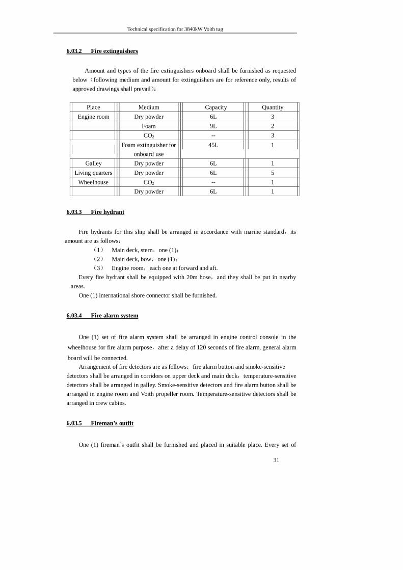
6.03.2 Fire extinguishers
Amount and types of the fire extinguishers onboard shall be furnished as requested below(following medium and amount for extinguishers are for reference only, results of approved drawings shall prevail):
Place Medium Capacity Quantity
Engine room Dry powder 6L 3 Foam 9L 2 CO2 -- 3
Foam extinguisher for
onboard use 45L 1
Galley Dry powder 6L 1 Living quarters Dry powder 6L 5
Wheelhouse CO2 -- 1 Dry powder 6L 1
6.03.3 Fire hydrant
Fire hydrants for this ship shall be arranged in accordance with marine standard,its amount are as follows:
(1) Main deck, stern,one (1); (2) Main deck, bow,one (1); (3) Engine room,each one at forward and aft.
Every fire hydrant shall be equipped with 20m hose,and they shall be put in nearby areas.
One (1) international shore connector shall be furnished.
6.03.4 Fire alarm system
One (1) set of fire alarm system shall be arranged in engine control console in the
wheelhouse for fire alarm purpose,after a delay of 120 seconds of fire alarm, general alarm
board will be connected. Arrangement of fire detectors are as follows:fire alarm button and smoke-sensitive
detectors shall be arranged in corridors on upper deck and main deck,temperature-sensitive detectors shall be arranged in galley. Smoke-sensitive detectors and fire alarm button shall be arranged in engine room and Voith propeller room. Temperature-sensitive detectors shall be arranged in crew cabins.
6.03.5 Fireman’s outfit
One (1) fireman’s outfit shall be furnished and placed in suitable place. Every set of
Technical specification for 3840kW Voith tug
32
fireman’s outfit shall be consisting of:air-breathing apparatus, protective mask, helmet,
gloves and boots, fireproof lifeline and fire fighting axe.
6.04 External fire fighting system
6.04.1 General
This system is furnished with one (1) set of fire pump, fire pump set is driven by clutch
and gear box connected at the free end of left main engine. Each fire fighting gun shall be
arranged at portside and starboard of the compass deck respectively,fire fighting gun are
required to be able to use rinsing water and foam, fire fighting capacity of each gun shall
be able to reach 600m3/h,fire fighting gun can be either remotely operated by the handle
fixed in the navigation console,or operated through manual method at the gun side.
Water screen with a flow rate of 300m3 shall be furnished.
For detailed specification and installation requirement of the outboard firefighting
system, please see the product specification provided by maker.
6.04.2 Fire fighting pump set
One (1) set of external fire fighting pump with a rated capacity of 1500m3/h – 140mwc
shall be furnished onboard,this pump shall be PTO driven by left engine.
6.04.3 Fire fighting gun
Two (2) sets of fire fighting guns with a flow rate of 600m3/h shall be furnished
onboard.
Control method: Electric remote control
Emergency maneuver: Manual turning wheel control
Rotating magnitude: Horizontal ±1650
Vertical +700 - -700
Material: Stainless steel and bronze
Driving type: Motor-driven
6.04.4 Control module
One (1) control module shall be supplied and integrated into wheelhouse by shipyard for
the purpose of remote control of fire fighting pump station and fire fighting gun.
Following units shall be included:(all the switches are required to be with indication
Technical specification for 3840kW Voith tug
33
lights) Fire fighting gun control:
One (1) power source switch with indication light (220VAC,1 phase, 50Hz)
One (1) control switch with indication light for the exchange of wheelhouse control/hand held controller Two (2) handles for control of fire fighting gun turning in left, right, front and back direction. Two (2) buttons for switching control between spout ejection type and spray ejection type of fire fighting gun
Clutch control: One (1) 24VDC power source with indication light
One (1) fire fighting mode indication light (only when the fire fighting mode instruction is received, can engaging operation for clutch be allowed, fire fighting mode signal is provided by main engine/Voith propeller system, after the clutch was engaged, one set of signals will be transmitted to main engine/Voith propeller system for interlocking ) One (1) silencing button One (1) set of buttons with lights for control of the clutch One (1) high temperature warning indication light One (1) system low oil pressure warning indication light One (1) clutch low oil pressure warning indication light
One (1) buzzer
Technical specification for 3840kW Voith tug
34
Part 7 Navigation and communication equipment
7.01 Navigation lights and signal lights
In accordance with the Rules, DC24V double bulb type navigation lights and search lights
with stainless steel housing shall be furnished onboard. All the navigation lights and signal lights
are all powered by two lines of DC24V power sources:one line shall be supplied by the power
after AC220V / DC24V transformation from main switchboard,the other line powered by DC24V
emergency charging/discharging board.
Spare parts delivered with the ship shall be in compliance with the requirements of
unrestricted navigation zone stipulated in CCS rules.
7.01.1 Navigation lights
Following navigation lights shall be furnished onboard this ship:
Mast light (white), double bulb type 3 sets
Starboard light(green), double bulb type 1 set
Portside light (red), double bulb type 1 set
Stern light (white), double bulb type 1 set
Towing light (yellow), double bulb type 1 set
Anchor light (white), double bulb type 1 set
Not under command light ,single bulb type 3 sets
7.01.2 Signal lights
This ship shall be furnished with following signal lights:
Portable flash signal light 1 set
Port signal light 1 set
7.01.3 Search lights,projection light
One (1) 1000W imported search light shall be fixed on the top shelter of wheelhouse, housing
of which is of stainless steel, it can be electrically controlled by remote method from wheelhouse
console. Two (2) sets of light receptacle-assemblies and bulbs shall be provided as spare parts.
Two (2) 500W projection lights shall be furnished at fore and aft ends of navigation deck
each.
Technical specification for 3840kW Voith tug
35
7.01.4 Siren
One (1) siren shall be fixed on the mast which is on top of the wheelhouse; control button
shall be installed on the maneuvering console.
7.01.5 Window wiper
One (1) electrically operated wiper shall be fixed on each window glass of the four sides of
the wheelhouse; switch shall be installed on the maneuvering console. The wipers shall be
with the function of rinsing as much as possible.
7.02 Telecommunication equipment
Configuration of the wireless telecommunication equipment GMDSS system onboard this ship shall be in compliance with the CCS Rule requirement for A1+A2 navigation zone. Following equipment shall be included:
7.02. 1 Public address system
One (1) 100W loud speaker system (with electronic tuning receiving head)shall be
installed in wheelhouse. Two (2) 25W loud speaker(drip proof type)shall be installed in
main mast,a certain number of 3W speakers shall be separately installed in wheelhouse,
engine control room, mess room and each cabin,two (2) 5W speakers shall be fixed in
engine room and Voith propeller room. Two (2) microphones and two (2) remote control
sockets.
7.02.2 Sound-powered telephone,program-controlled telephone
One (1) set of sound-powered telephone shall be furnished onboard for convenient
contact between wheelhouse and engine monitoring room, the telephone in engine
monitoring room shall be furnished with visual and audio display in engine room.
One (1) set of program controlled telephone system consisting of 12 telephones shall be
provided onboard, the telephones shall be arranged in wheelhouse, mess room, each
accommodation cabin, engine monitoring room and engine room. The telephone fixed in
engine room shall be with visual and audio indication function.
Technical specification for 3840kW Voith tug
36
7.02.3 Main engine emergency telegraph
One (1) set of emergency telegraph for left and right emergency telegraph respectively
shall be furnished in wheelhouse and engine monitoring room and main engine
maneuvering position(provided by main engine maker for the complete set),with audio and
visual warning function,power source is DC24V.
7.02.4 VHF telephone
This ship shall be furnished with one (1) JRC or Furuno VHF wireless telephone,one (1)
ICOM VHF wireless telephone,one of which shall be with DSC function,power source is
AC220V/DC24V,they all adopt rod antenna.
This unit shall be able to work with voice and DSC in single frequency channel or in
single and double frequency mode,frequency range is 156.0~174.0MHz. It shall be the
specialist digital selection calling duty device which is able to guard and listen continuously
in 70 frequency channels, it shall be furnished with the function of visual indication that the
equipment is in working condition as well as conducting the transmitting task. With high
anti interference ability, it shall not be damaged in case of antenna open circuit or antenna
terminal short circuit. One motoring speaker shall be arranged in mess room.
7.02.5 MHF wireless telecommunication unit
This ship shall be furnished with JRC,Furuno or mid/high frequency wireless
telecommunication unit,with one set mid frequency DSC terminal,they shall be in
compliance with the GMDSS requirement,frequency range of the transmitting units shall
be:1605~27500 kHz. The selected transmitting frequency shall be clearly recognized in the
control panel of the unit. Power source is AC220V/DC24V.
7.02.6 NAVTEX
One (1) set of NAVTEX receiver (JRC or Furuno)shall be furnished onboard,,it shall
be arranged in wheelhouse,receiving frequency is 518kHz,powered by AC220V/DC24V
source.
7.02.7 Life raft two-way VHF telephone
Two (2) life raft use two-way VHF wireless telephones shall be furnished onboard for
site communication between life rafts, life raft and ship, life raft and rescue units.
Technical specification for 3840kW Voith tug
37
Norwegian products shall be used.
7.02.8 SART
One (1) SART shall be arranged onboard this ship, it can display the position of the
distressed on the radar of the rescue unit by a series of evenly distanced dots,it shall be
furnished the anti-accidental starting function, visual or audio unit, or visual and audio unit
to indicate correct operation,and remind survivors,SART can also be activated by search
radar. Frequency range :9200~9500MHz.
Norwegian products shall be used.
7.02.9 800 M group telephone
One (1) 800M group telephone shall be furnished onboard for contact between ship and
shore directing.
7.02.10 Sound-controlled voice recorder
One (1) digital sound controlled voice recorder shall be furnished onboard, it can
automatically record 8 hour continuous VHF voice signal. It can also record synchronously
the voice content and time as the call occurs.
7.02.11 Walky- talky
Two (2) hand-held VHF all-channel walky-talky (Motorola)shall be furnished onboard
the ship.
7.02.12 EPIRB
One (1) Emergency Position Indicating Radio Beacon(EPIRB)shall be furnished
onboard.
7.02.13 All-frequency antenna
One (1) set of all frequency antenna shall be furnished onboard the ship, TV feedback
cable shall be of 75Ω co-axial cable with plastic protection sheath. .
Technical specification for 3840kW Voith tug
38
7.03 Navigation equipment
7.03.1 Radar
One (1) marine radar with APPA function and 12 inch display shall be furnished
onboard, radar antenna shall be fixed on the mast, maximum display distance shall be
≥48 nautical miles, transmission power ≥6kW, power supplied by AC220V power
source.
7.03.2 Sounder
One (1) set of sounder shall be provided in the wheelhouse,power source is
AC220V,DC24V.
7.03.3 Anemorumbometer
One (1) set of imported marine anemorumbometer shall be furnished onboard the
ship, its type is of N-54C and installed in wheelhouse,power source is AC220V,
DC24V.
7.03.4 Repeat magnetic compass
One( 1) imported standard compass(vertical),one (1) steering compass (desk type),
dial diameter are both of 165mm,∮ lighting power source is DC24V. Steering compass
can automatically trace standard compass,indication tolerance are both less than 0.5°.
GPS,radar,AIS connection ports shall be provided.
7.03.5 DGPS
One (1) DGPS shall be furnished in the wheelhouse,power source is AC220V,
DC24V.
7.03.6 Weather facsimile recorder
One (1) set of FAX-207 weather facsimile recorder shall be furnished onboard the
ship, power source is AC220V,DC24V.

Technical specification for 3840kW Voith tug
39
7.03.7 Automation Identification System(AIS)
One (1) set of Automation Identification System(AIS)shall be provided,signals from
DGPS, radar and magnetic compass can be received,connector for pilot use shall be
furnished,power source is AC220V,DC24V.
7.03.8 Others
One (1) laptop computer with a famous brand shall be furnished for this ship.
Technical specification for 3840kW Voith tug
40
Part 8 Main Engine Room Equipment
8.01 General
A double-engined and double azimuthing Voith propulsion system to be adopted in the ship.
(1) Working conditions:
Normal operation and consecutive power to be guaranteed for all machinery and
accessories under design conditions as follows:
Atmospheric pressure 0.1Mpa
Ambient temperature 45℃
Relative humidity (RH) 60%
Sea water temperature 32℃
(2) Main engine: Four stroke, single action, direct injection, turbo-charged, inter-cooling
system and irreversible type marine diesel engine. The turbo-charger’s layout to meet the need of
upper fume exhaust.
(3) Propeller: Voith Schenieder propeller.
(4) Diesel engine generators: two diesel engine generator sets to be installed, each serving as
standby of the other and transferring load between the two under no power off.
(5) Other mechanical equipment: running consecutively under rated output.
(6) Monitoring room: Displays and audible and visual alarms to be installed under the
requirements of the Rules and Regulations. The operation of the main engine and clutches can be
remotely controlled in the wheelhouse. The startup and normal shutdown of the main engine to be
run beside the main engine and emergency stop button to be installed in the wheelhouse.
(7) The layout of all machinery shall leave proper room for operation and maintenance.
(8) Spare and material storeroom with proper space to be laid out in the engine room or Voith
propeller room.
(9) The design, fabrication, construction, material, fittings and accessories of all the
machinery to meet the requirements of the Rules and Regulations and to have product certificates
issued by China Classification Society (CCS). Torsional vibration calculation to be made in the
design of the shafting and submitted to the classification society for approval.
(10) Daily service fuel oil tank, fresh water expansion tank and lubricating oil storage tank to
be laid out in the engine room (with the interior bottom of the daily service fuel oil tank and fresh
water expansion tank in the conical shape for blowdown purpose).
(11) All the diesel engines to burn CB252-87 0# light diesel fuel.
Technical specification for 3840kW Voith tug
41
8.02 Main engine
The ship to adopt two sets of 6EY26 type marine diesel engine as the main engines:
four stroke, single action, direct injection, turbo-charged, inter-cooling, irreversible,
energy-saving and environment-friendlly.
Continuous rating: 1920kW
Rated rotation speed: 750rpm
8.02.1 Lubricating oil system of main engine
Self-driven lubricating gear pump, automatic oil temperature regulator, pressure
regulating valve, lubricating oil filter, tubular cooler to be laid out for each main engine. An
independent lubricating circulating tank to be laid out to meet the lubricating need of the
main engine. To prevent the self-driven lubricating gear pump from failure, a standby
electric gear pump (supplied in package with the main engine) to be laid out for emergence
use.
8.02.2 Cooling system of main engine
Each main engine set to have one self-driven fresh water pump and one electric sea
water pump while the lubricating oil cooler, fresh water heat exchanger and air cooler to be
supplied in package with the main engine, whose structures are convenient to be maintained
and free from air and sewage blockage. Automatic temperature regulator to be equipped to
regulate the temperature of the circulating water and oil. General service pump to be
reliably connected with the sea water system to serve as standby cooling-water pump of the
main engine. One electric fresh water pump to be equipped as standby to be used by the
main engine (supplied in the package with the main engine).
8.02.3 Air startup system of main engine
Main engine to be equipped with two startup air cyclinders, whose capacity can start
up each main engine set in cold state for six consecutive times without gas charging. The air
cylinder, with the maximum startup air pressure of 2.94Mpa (30kgf/cm), to be equipped
with safety valve, drainage valve and piping of condensed water.
8.02.4 Exhaust system of main engine
Each main engine set to be equipped with exhaust silencer (with dry spark
extinguisher) and suction filter. The exhaust-gas turbocharger’s outlet to be with corrugated
Technical specification for 3840kW Voith tug
42
type expansion joint, and the main engine exhaust pipe and exhaust-gas turbocharger to
have good thermal protection with the maximum temperature of the external surface less
than 60 .℃
8.02.5 Fuel oil system of main engine
Each main engine set to be equipped with self-driven fuel oil transfer pump with
safety valve, fuel oil twin strainer, single cylinder inject pump, leakage oil collecting tank,
fuel injector, and etc.
Bypass pipes to be laid out in the pipelines of the fuel oil supply pump.
8.02.6 Speed control system of main engine
Each main engine set to be equipped with a mechanical hydraulic speed governor
(manufactured by Wood Word), controlling the main engine’s speed within its whole speed
range with good performance. The main engine’s speed to be controlled in the wheelhouse
or in the engine room.
For oil saving purpose, the rotation speed of the main engine to be fixed at the
following stages, controlled by the indicator button mounted on the maneuvering console:
Stage 1 at 100% rpm full power for towing and free running
Stage 2 at 90% rpm partial power for work
Stage 3 at 80% rpm partial power for work
Stage 4 at 60% rpm minimal work speed
Stage 5 at 40% rpm Idle speed
Each main engine to have over-speed protection function, meeting the requirements of
the Rules and Regulations.
8.02.7 Instruments of main engine
Each main engine set to be equipped with the running hour counter. The instruments
on the instrument panel to indicate correctly main working conditions during the running
of the main engine. The main body of the main engine set to be equipped correspondingly
with instruments indicating each part and working conditions of the system. A set of
instrument and alarm device also to be mounted in the monitoring room to monitor the
running of the main engine.
8.02.7 Documents and drawings of main engine
The manufacturer of the main engine to supply a complete set of product approval
Technical specification for 3840kW Voith tug
43
documents, working documents and completion documents, two compact discs and six
sets of copies respectively of operating specifications, maintenance instruction and after
service manuals, product certificates issued by CCS, Nox certificates and torsion
vibration calculation.
8.03 Propulsor
This vessel to be equipped with two sets of 28 RΠ/210-2 type Voith–Schenieder
propulsors.
Turning diameter of blade: 2800mm
Length of blade: 2100mm
Quantity of blade: 5pcs
Material of blade: drop forged anticorrosive alloy steel
Rotation speed of propulsor: 76rpm
8.03.1 Rotation direction of propulsor
Looking downwards from the top of the propulsor:
Right propulsor: clockwise
Left propulsor: counterclockwise
8.03.2 Rotation direction of main engine
Looking from propulsor to output shaft of the main engine:
Right main engine: clockwise
Left main engine: counterclockwise
Refer to the technical specifications and installation manual of the propulsors provided
by Voith for detailed technical specifications and installation requirements.
8.04 Diesel generator set
The ship to be equipped with two homemade generator sets, with one meeting the
requirements of the ship’s work and the other serving as standby. The two generator sets can
transfer load under no power off.
The prime mover of the generator to adopt homemade CUMMINS diesel engine, which is
vertical four stroke, freshwater closed-circuit cooling, direct-injection and irreversibel marine type
diesel engine and can match with the generator’s power. The generator to adopt homemade
Siemens-brand product.
The generator set to be started up by compressed air and equipped with air motor, starting
Technical specification for 3840kW Voith tug
44
valve, reducing valve, oil sprayer, safety valve and pressure gauge.
The generator set to have a common foundation, installed in the hull via shock absorber.
Lubricating oil thermometer, lubricating oil pressure gauge and tachometer of the prime
mover to be installed on the generator set.
The alarm system to be equipped with the following audible and visual alarms:
High temperature of fresh water (alarm),
High temperature of lubricating oil (alarm),
Low pressure of lubricating oil (alarm and shutdown), and
Over-speed shutdown (alarm).
All the above indicators and alarm signals to extend to the alarm chest in the monitoring
room of the main engine and comprehensive alarm to be set on the wheelhouse console.

Technical specification for 3840kW Voith tug
45
Part 9 Piping and ship system
9.01 General
All the pumps and pipings of the ship to be laid out according to corresponding requirements
of the Rules and Regulations of CCS.
All pumps to be of proven marine products and with CCS certificates as required. The
products selected to have spares that are easy to find at the market. The impeller of the selected
water pumps to be made with bronze and shaft with stainless steel and mechanically sealed. The
shafts of the oil pumps to be made with forged steel and mechanically sealed. All sea water pumps
to have bronze shell, fresh water pumps to have cast iron shell, and oil pumps to have cast steel
shell. All pumps to be equipped with pressure gauges as required.
9.02 Materials and construction requirements of the piping
9.02.1 Piping materials
The piping materials can select 20# high-quality structural seamless carbon steel pipes,
hot galvanized steel pipes, stainless-steel pipes and copper pipes, etc. Seamless steel pipes
of each specification to be thickening-wall type. The materials of all piping and flanges
above the main deck as well as connection bolts and nuts to be stainless steel.
9.02.2 Materials of valves, sea water filters and butterfly valves
Specifications and models of the valves, flanges and accessories of all piping to meet
the marine product requirements stipulated in GB and CB standards, and products
manufactured by Jiangyan Marine Valve Factory or Hudong Marine Valve Factory to be
selected. All the sea/fresh water valves to select cast steel (bronze valve core and bronze or
stainless steel valve rod), copper or stainless steel according to its purpose. The valves of
the fuel/lubricating oil system to choose cast steel material ones. The valves above the main
deck and overboard discharge valves to choose bronze or stainless steel ones. The valves
and faucets of living water to choose products with TOTO or American Standard brands.
The filter mesh of the sea water filter and the valve rod, lining and valve core of the
sea water butterfly valves to adopt stainless steel materials. The filter mesh of the main sea
water filter to be made of hole-drilled stainless steel panel in proper thickness and fastened
with the main body.
The sea water valve, sea water filter and bolt and nuts to be fastened with the hull to
adopt stainless steel materials.
Technical specification for 3840kW Voith tug
46
9.02.3 Gasket materials
(1) Medium and high pressure salamandrite gaskets to be used in sea water system,
cooling fresh water system, bilge ballast water system, and lubricating/fuel oil system. Black
butadiene nitrile rubber gaskets to be used in compressed air system, drain and leak-off
system, oily water sewage disposal system, gas venting system, sounding system and filling
system.
(2) Red fluororubber gaskets to be used in daily service fuel oil system.
(3) Red copper gaskets to be used in compressed air system of the main engine (concave
and convex flanges).
(4) CS828A spiral wound gaskets or products of the same kind to be used in exhaust
system of the main engine with a temperature above 150℃.
(5) White silicone rubber gaskets to be used in water supply system and living water
system of the main engine.
9.02.4 Piping preservation
(1) Main sea water pipes, sea water cooling pipes, fire pipes (internal firefighting of the ship)
and bilge ballast pipes to be plastic coated inside the pipe wall and preservatively treated by
derusting outside the pipe wall. The external firefighting pipes and other types of water
pipes to be processed with double-face hot galvanization. Bulkhead-penetrating pipes to
have proper measures to prevent its coating from damage. In case the coating is damaged, it
to be repaired with proper processes.
(2) When the fabrication of the fuel/lubricating oil piping finishes, the inner walls of the
pipes to be coated with medium oil after chemical cleaning. The flushing of the lubricating
oil piping of the main engine to be no less than 72h, especially the piping between the
lubricating oil fine filter of the main engine and the main engine. During flushing, the pipes
to be knocked and shocked constantly to clean out small containment inside the pipes.
(3) Flanges specially used in the hydraulic piping or square flanges of high pressure
connection to be chemically cleaned as a whole after finishing the piping fabrication with
medium oil coated on the inner wall and anti-rust painted on the outer wall. After
installation, the whole system to be oil flushed, lasting longer than 48h.
(4) The compressed air piping to be galvanized after acid cleaning and connection to be
made with high-pressure flange or bushing.
(5) All the water-feed pipes in the fresh water tank, vent pipes and sounding pipes to use
stainless steel pipes.
Technical specification for 3840kW Voith tug
47
9.02.5 Prefabrication and welding of piping
Pipes with a diameter less than 100mm to be bent by pipe-bending machine. Pipes in
need of welding-on elbows or bends ,these elbows or bends to be of standard, thickening
and qualified products made by qualified manufacturers.
Reducing coupling and floor drains to be of the same materials as those of the pipes,
and the wall thickness to be no less than the pipe’s wall thickness.
The connection base plate between the overboard discharge valve and discharge outlet
to be made of 35# steel. The tip end of the base plate to stand out 10mm to the side plate for
the convenience of welding.
All the valve opening in the checked plate of the main engine to be pressed or bored
and equipped with foot press type coverage device.
The butt joints of the pipes, the welding of the elbow and the pipes, and the welding of
the flanges (high pressure ones) and the pipes to use CO2 gas shielded arc welding. Each
pipe to have proper length for the benefit of future piping maintenance. Each pipe to have
only one elbow and no more than two in special cases.
The connection of bulkhead-penetration pipes to adopt sleeve type.
Each variety of piping to go through shop pressure test and onboard system pressure
test after installation according to the Seller’s building and test processes with the
participation of the Buyer’s representative.
9.02.6 Piping marking
The piping of the ship to be marked with arrow sign to show the liquid flow direction
in the following colors:
Sea water dark green
Fresh water light grey
Oily and bilge water black
Firefighting red
Fuel oil iron red
Lubricating oil deep yellow
Compressed air sky blue
Hydraulic oil light yellow
Technical specification for 3840kW Voith tug
48
9.03 Ship system
9.03.1 Cooling system
Main sea chests to be arranged at both sides of the engine room, connected by main
sea pipes. Each sea chest to have one main sea valve. The sea chest to be equipped with bar
filter, whose flow area is three times larger than the cross-sectional area of the main sea
pipes. The sea chests to be equipped with air pipes, compressed air pipes and blow valves.
Another sea chest to be arranged in the intermediate back of the engine room, independently
used by external firefighting sets.
The self-driven pumps and other electric pumps of the main/aux. engine to absorb
water from main seawater pipes. The design of seawater filter and the bore of seawater
pipes to meet flow quantity requirements in case of simultaneous seawater use by all
equipment of the ship and no phenomenon of scrambling for water to appear.
The cooling system of the main/aux. engine to be configured as required by the Rules
and Regulations. General service pumps to serve as standby seawater cooling pumps of the
main/aux. engine. The standby freshwater cooling pumps of the main engine to be
configured independently. The air-conditioned cooling pumps to serve as the standby
seawater cooling pumps of the auxiliary engine. The cooling water for Voith propeller and
clutches to be supplied by the cooling system of the main engine. The cooling system’s
freshwater supply of the main/aux. engine to be made by the water pressure tank.
9.03.2 Fuel oil system
This system includes fuel oil transfer, supply and discharge. It to consist of two fuel
oil transfer pumps (one as standby), one flow meter in the oil pipeline to the daily service
oil tank and one fuel oil filter with adequate flow area. The daily service oil tank to be
equipped with self-closed glass liquidometer and low-level alarm device and to make it
possible for the fuel oil transfer pumps to supply oil automatically or manually. In the fuel
oil system, all residual fuel to be discharged to the dirty oil tank and to be transferred ashore
via dirty oil pumps.
The filling inlets of the fuel oil tanks to be separately laid out in proper locations at
both sides of the main deck so that the fuel oil tank can be charged at each side. The outlet
of the air pipes to be equipped with the flame screen. The upper deck to be equipped with
the engine room speed-cut valve chest. In case of fire accident in the main engine, the daily
service oil tank in the main engine can be shut off by remote control. Other kinds of
allocations and alarm devices to be configured according to the Rules and Regulations.
Technical specification for 3840kW Voith tug
49
9.03.3 Lubricating oil system
This system to consist of lubricating oil transfer, supply and discharge. It to be
equipped with lubricating oil circulating tank and lubricating oil storage tank and
independent filling inlet laid out in the main deck. The lubricating oil of the main engine to
be supplied by main engine-driven lubricating oil pumps via lubricating oil cooling unit,
temperature regulating valve, lubricating oil cleaner to each lubrication point. In case of
malfunction of the main engine-driven lubricating oil pumps, or pre-supply of lubricating
oil before starting up of the main engine as well as pumping ashore lubricating oil from the
lubricating oil tank, the function to be fulfilled by standby lubricating oil pumps of the main
engine. The Voith propeller, diesel engine generating sets and firefighting sets to contain
lubricating oil pumps with themselves and form independent lubricating oil circulation
systems. For convenience of oil-quality monitoring, lubricating oil sampling valve to be laid
out in the pipelines between the main engine and its condenser (one at each engine). The
waste oil of the lubricating oil system and other kinds of residual oil to be discharged to the
dirty oil tank. Other kinds of configuration and alarm devices to be laid out according to the
Rules and Regulations. The lubricating oil circulating tank to be equipped with one set of
mechanical level display unit.
9.03.4 Compressed air system
This system to consist of compressed air systems for startup of the main engine and
the diesel generating sets and compressed air system for miscellaneous use.
This system to include two sets of main air compressors, two sets of main startup air
cylinders and one air cylinder for startup of the auxiliary engine and miscellaneous use. The
two sets of air compressors can supply air respectively or simultaneously and automatically
start or stop according to the pressure of the air cylinders. The air compressor charges the
main startup air cylinder directly via gas, oil and water separator. Additionally, one set of
manual emergency air compressor to be configured with a displacement of 0.1m3/min.
The main startup air cylinder to supply air to the main engine starter and auxiliary air
cylinder.
The compressed air capacity of the two sets of main startup air cylinders to meet the
requirements of six times of cold startup of the two main engines. The compressed air
pressure of the main engine’s startup to be determined according to the main engine’s
requirement.
The remote control air of the main engine to be supplied by main air cylinder after
pressure reduction and filter via air source panel.
The auxiliary air cylinder to supply air for diesel generating set’s startup and
Technical specification for 3840kW Voith tug
50
miscellaneous use of air source of air/fog whistle, flushing of sea valves and blow wash of
the engine room and the deck.
9.03.5 Living water system
A set of combined type sea/fresh water pressure tank, made of stainless steel, to be
located in the engine room. The combined type water pressure tank to have one sea/fresh
water pump and one standby pump of the same specification (referring to 3.2.5 for the
materials), mounted on the body of the water pressure tank. A pressure relay to be mounted
on the tank body to control the pumps automatically. The water pressure tank to supply
fresh water to the galley, bathroom, main/aux. engine expansion tanks, and etc. The
gravitation water tank to be connected with the outlet pipe of the fresh water pressure tank.
The sea water pressure tank to supply sea water to places like toilets.
The pipes of living fresh water and hot water to be all made of stainless steel. The wall
thickness of the pipes can meet the requirements of water pressure intensity.
9.03.6 Exhaust system
The main/aux. engine and diesel engine for fire control to adopt the type of upper
fume exhaust and double funnel. The engines to discharge via the supercharger’s outlet
through the expansion joint, exhaust silencer with spark extinguisher and exhaust pipe to
the atmosphere.
Expansion joints and supports to be laid out in proper places of the whole pipeline.
The exhaust pipes of the main/aux. engine and diesel engine for firefighting to be wrapped
with insulating materials and the external surface temperature of the exhaust pipes after
thermal insulation wrapping shall not exceed 60℃.
9.03.7 Bilge ballast water system
This system to have one self-priming bilge and ballast pump. The main fire pump and
bilge pump to serve as standby of each other or use jointly.
The bilge well to be located at proper spaces of both sides of the engine room. Both
sides of the bilge well to have direct bilge mouth and bypass mouth. The bilge bypass
mouth to have unidirectional non-return filter and the direct mouth to have a mud box.
A jet pump to be laid out to discharge bilge water in the chain locker.
The bilge water system to be equipped with an oil-water separator meeting the
requirements of the Rules and Regulations with a capacity of 0.25 m3/h. After separation of
the dirty oil-water, the water with oil content of less than 15ppm to be discharged overboard
Technical specification for 3840kW Voith tug
51
and the oil to be collected in the dirty oil tank. The dirty oil in the dirty oil tank to be
transported ashore through a special-purpose dirty oil pump via shore connection of the
main deck
The quantity and location of the ballast tanks to be determined during the ship design.
The ballast pumping system to have multiple unit valve boxes for the transfer of the ballast
water.
9.03.8 Internal fire system of the vessel
The firefighting water of the water fire-extinguishing system of the ship to be supplied
by a main fire pump in the engine room and a bilge and ballast pump (concurrent use). The
fire hydrants and extinguishers to be installed according to the Rules and Regulations. The
pipe line of the firefighting system can be used concurrently for flushing the deck and
anchor chains. The displacement of the main fire pump to meet the requirements of serving
as standby of the cooling seawater pump of the main engine.
A fire hydrant to be emplaced at each boardside and matched with one international
shore connection.
This ship to be equipped with one set of foam fire extinguisher (45L) of vessel and
vehicle use type.
9.03.9 Discharging and drainage system
This system to include discharging, drainage, and treatment of sanitary sewage.
The discharging and drainage of all the basins, wash basins, bathrooms, laundries and
galley to be concentrated in proper groups and treated according to relevant regulations by
the marine bureau. In emergency case, it can be discharged overboard via storm valves.
Gutters to be located at the base of four walls in the wheelhouse.
Sewage treatment plant to be also included in this system, whose specifications to be
configured according to the ship’s practical situations. The plant to treat the sanitary sewage
of the ship, which is discharged to the water area after meeting effluent standard. In
emergency case, the sanitary sewage can be discharged directly.
9.03.10 Air pipe, sounding pipe and filling pipe
The foam tank, oil-water tank, oily water tank, void compartment and all sea chests to
be equipped with air pipes, whose cross-sectional area and height to be determined
according to the Rules and Regulations.
The air pipes of the lubricating oil circulation tank, fuel oil tank and daily service oil
Technical specification for 3840kW Voith tug
52
tank to extend to the decks and to have metalic flame screens and pipe caps at the top ends
of air pipes of the oil tanks and chests.
The depth sounding of the water tank and oil tank use self-closing depth sounding
valve, extending to the accessible place in the checker plate with protective shield mounted
at its end. The filling inlets of the liquid tanks to be collectively arranged at both sides on
the main deck. The specific location and installation to be determined during ship design
according to the requirements of the Rules and Regulations.
9.03.11 Air conditioning system
The air conditioning system of this vessel to use Daikin-brand center air conditioner
with water-cooled air conditioner installed one in each of the crew space, conference room,
captain’s room, chief engineer’s room, officer’s room and monitoring room. An independent
ceiling suspended air conditioner to be installed in the wheelhouse. If the external
temperature is 38℃ in summer, the indoor temperature to be controlled to 28℃ or below.
The air-conditioner to choose rectangular duct with stainless-steel spherical diffuser
mounted at its end. An air-conditioned cooling sea water pump with brass shell, stainless
steel shaft and bronze impeller to be installed. The starting device of the center air
conditioner set to be interlocked with the air-conditioned cooling water pressure and the air
conditioner cannot be started in case the pressure of the air-conditioning cooling water is
too low.
9.03.12 Ventilating system
The engine room to be mechanically ventilated with two sets of reversible axial flow
fan-ventilators mounted on the engine room casing. The configuration of the engine room
ventilator to meet the requirements for heat dissipation of the engine room and for fresh air
of the internal combustion engine. The ventilators to be allocated as required by the Rules
and Regulations and to choose matching caps.
The crew space to be equipped with axial flow fan ventilators.
The mechanical ventilation system to have emergency cutoff device.
The storage battery room and storeroom to have fresh air inlet.
The bathroom, washroom and toilets to mount one exhaust fan in each.
9.03.13 Hydraulic oil system
The hydraulic oil system supplies hydraulic oil with a pressure of 200-240 bar, mainly
used to drive the deck machinery. It consists of:
Technical specification for 3840kW Voith tug
53
One main hydraulic pumping station connected to the right main engine via PTO,
and
One auxiliary motor-driven hydraulic pump with electric starting box, whose
power is 20% of that of the main hydraulic pumping station.
9.04 Tools and storeroom of the engine room
9.04.1 Tools
The engine room of this ship to be equipped with the following items: one fitter’s
bench, one 200mm bench vice, one electric drilling machine with max. drilling diameter of
Φ13mm, one Φ150m desktop electric sanding machine, one main/aux. engine oil nozzle
testbed , one tool rack and one set of daily service equipment.
Two pieces of engine tool shelves and one piece of note board.
Two equipment boxes in the control room.
9.04.2 Storeroom
This ship to be equipped with one storeroom for large-size tools and mechanical
spares at the backside of the engine room, having internally racks and drawers with lockup
device. The specific quantities and specifications to be determined during ship design.
Technical specification for 3840kW Voith tug
54
Part 10 Monitoring and Alarm System
10.01 General
The local monitoring and alarm devices for the machinery and the monitoring and alarm
devices in the engine monitoring room to be provided in accordance with Rule requirements.
Monitoring and alarm devices for important equipment to be supplied by the manufacturers
according to requirements concerned.
Propulsion plant is required to be remotely controlled from wheelhouse console.
Alarms for all equipment to be centralized and indicated respectively in the monitoring
rooms located in engine room and in the wheelhouse. (Items of alarms and indicators are as
specified in 8.05 of the Specifications)
10.02 Wheelhouse console
Two wheelhouse consoles are to be separately arranged at port and starboard sides and at the
fore part of the wheelhouse. A chair to be fit on slide rails between the two wheelhouse
consoles. Following items to be installed in the wheelhouse consoles:
(1)Tachometer for main engine (2×)
(2)Push buttons for step-control of main engine revolution
(3)Emergency stop push button for main engine (2×)
(4)Generator running indicating light(2×)
(5)Light modulator knob/ switch
(6)Switches of various navigation equipment(referred to Part VII)
(7)Centralized alarm panel(referred to 10.01)
(8)Double- speed changeover switch for wheelhouse window wipers with interval wipe and
water spray functions (depending on the functions of the products actually selected)
(9)General alarm switch with reset function
(10)Push button for cutting off fan and oil
(11)Sound powered telephone
(12)Remote control handle for search light
(13)Control modules for warping winches and windlass
(14)Control panel for external fire-fighting system
(15)Air horn push button
The purchased manoeuvring console for the propeller of the Voith to be equipped with
following items:
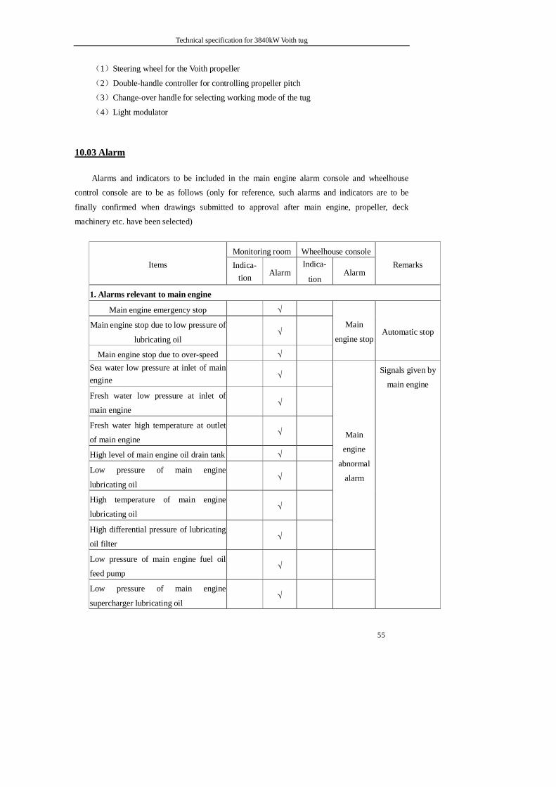
Technical specification for 3840kW Voith tug
55
(1)Steering wheel for the Voith propeller
(2)Double-handle controller for controlling propeller pitch
(3)Change-over handle for selecting working mode of the tug
(4)Light modulator
10.03 Alarm
Alarms and indicators to be included in the main engine alarm console and wheelhouse
control console are to be as follows (only for reference, such alarms and indicators are to be
finally confirmed when drawings submitted to approval after main engine, propeller, deck
machinery etc. have been selected)
Monitoring room Wheelhouse console Items Indica-
tion Alarm Indica-
tion Alarm
Remarks
1. Alarms relevant to main engine
Main engine emergency stop √
Main engine stop due to low pressure of
lubricating oil √
Main engine stop due to over-speed √
Main
engine stop Automatic stop
Sea water low pressure at inlet of main engine √
Fresh water low pressure at inlet of
main engine √
Fresh water high temperature at outlet
of main engine √
High level of main engine oil drain tank √
Low pressure of main engine
lubricating oil √
High temperature of main engine
lubricating oil √
High differential pressure of lubricating
oil filter √
Main
engine
abnormal
alarm
Low pressure of main engine fuel oil
feed pump √
Low pressure of main engine
supercharger lubricating oil √
Signals given by
main engine
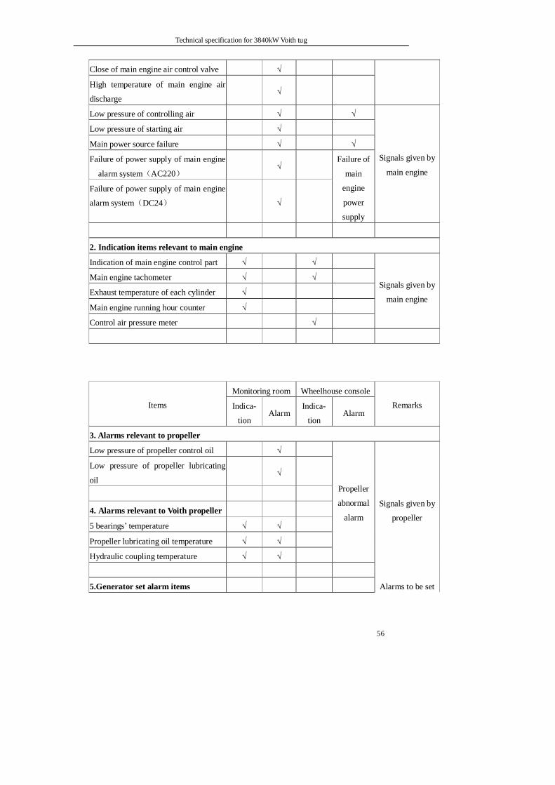
Technical specification for 3840kW Voith tug
56
Close of main engine air control valve √
High temperature of main engine air
discharge √
Low pressure of controlling air √ √
Low pressure of starting air √
Main power source failure √ √
Failure of power supply of main engine
alarm system(AC220) √
Failure of power supply of main engine
alarm system(DC24) √
Failure of
main
engine
power
supply
Signals given by
main engine
2. Indication items relevant to main engine
Indication of main engine control part √ √
Main engine tachometer √ √
Exhaust temperature of each cylinder √
Main engine running hour counter √
Control air pressure meter √
Signals given by
main engine
Monitoring room Wheelhouse console
Items Indica-
tion Alarm
Indica-
tion Alarm
Remarks
3. Alarms relevant to propeller
Low pressure of propeller control oil √
Low pressure of propeller lubricating
oil
√
4. Alarms relevant to Voith propeller
5 bearings’ temperature √ √
Propeller lubricating oil temperature √ √
Hydraulic coupling temperature √ √
Propeller
abnormal
alarm
Signals given by
propeller
5.Generator set alarm items Alarms to be set
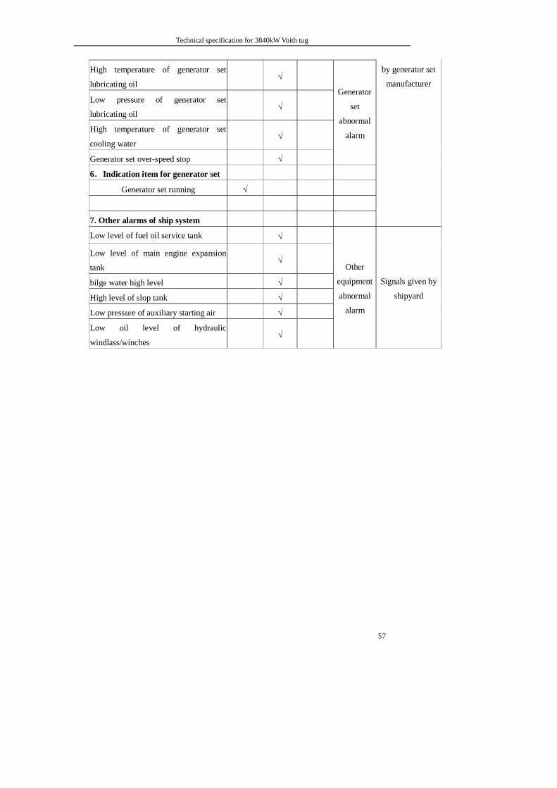
Technical specification for 3840kW Voith tug
57
High temperature of generator set
lubricating oil √
Low pressure of generator set
lubricating oil √
High temperature of generator set
cooling water √
Generator set over-speed stop √
Generator
set
abnormal
alarm
6.Indication item for generator set
Generator set running √
by generator set
manufacturer
7. Other alarms of ship system
Low level of fuel oil service tank √
Low level of main engine expansion
tank √
bilge water high level √
High level of slop tank √
Low pressure of auxiliary starting air √
Low oil level of hydraulic
windlass/winches √
Other
equipment
abnormal
alarm
Signals given by
shipyard

Technical specification for 3840kW Voith tug
58
Part 11 Electric equipment
11.01General
Design, construction, installation, test and commissioning (including electric wiring) of
main electric equipment and relevant material are to be comply with the current effective
Rules and Regulations for the Construction and Classification of Sea Going Steel Ships of
CCS, CB/T3909-1999 Technological Standard for Installation of Marine Electric Equipment
and Ship-owner’ s requirements simultaneously.
11.01.1 Protection degree of electric equipment
Protection degrees of electric equipment to satisfy following requirements:
(1) IP22 for those located in machinery spaces such as control rooms, Voith
propeller room, engine room etc..
(2) IP44 for those located in galley etc.
(3) IP56 for those located on the weather deck.
11.01.2 Voltage and frequency of power supply and distribution system
Voltage, frequency and distribution for electric equipment to be as follows:
Items Voltage Frequency Phase System
Generator AC400V 50Hz 3Φ Three-wire insulation
Motor AC380V 50Hz 3Φ Three-wire insulation
Lighting AC220V 50Hz 1Φ Two-wire insulation
Nautical equipment, Radio equipment
AC220V
DC24V 50Hz 1Φ
Three-wire insulation Two-wire insulation
Interior communication alarm
AC220V
DC24V 50Hz 1Φ
Two-wire insulation
Emergency lighting DC24V Two-wire insulation
11.01.3 Name plate and label
Main electric equipment such as main switchboard, engine room alarm panel, wheel
house control console, and control boxes each to be given a fixture type name plate
Technical specification for 3840kW Voith tug
59
indicating the application or name of the equipment. The name plate is to be made of
copper or flame retardant plastic material. There to be an identification label at both
ends of each main electric cable indicating the same number as specified in electric
system drawings.
11.01.4 Metal box casing of electric equipment are to be firm in construction and perfect in
configuration.
11.01.5 There to be a red scale indicating the rating value for all instruments.
11.01.6 Main switches, feeder circuit breakers, electric elements on main switchboard, shore
supply switch on the shore connection box are to be of Schneider products, and
feeder circuit breakers of section boxes, wheelhouse control panel, charging and
discharging panel etc, of Meilanrilan梅兰日兰 products.
11.01.7 Spare parts of all electric equipment to be provided in accordance with the Rules.
11.02 Cables
All cables to comply with GB and CB Standards together with the Rules. Rating voltages and
currents of electric cables are to comply with rated values of consumers or motors plus a margin.
Unless otherwise stated, electric cables to be of CEF92/SA,CEF82/SA. Cables for exterior
lighting, navigation lights, signal lights to be of CEF92/SA. Cables for electric circuits of main
engine and azimuthing Voith propeller, communication and nautical equipment and radio
equipment, of shielded CEF82/SA、CEFP80/SA. Connection wires within distribution boxes and
instrumentation boxes, to be of CBVR——type C marine polyvinyl chloride insulated. Conductor
cross-section of control cables to be 1.0mm2 .
For portable appliances such as portable hand lamps etc., cables to be of flexible rubber
insulated, polyvinyl chloride sheathed. Special cables such as coaxial cables, compensating cables
to be as specified or approved by equipment manufacturers. Enough spare cables to be provided
for running between important spaces such as wheelhouse, engine room, Voith propeller room.
In general, cables to be installed in bunch and on galvanized metal support bracket as far as
practicable. Where the cables are exposed to any mechanical damage, they are to be protected by
steel conduit, steel plate or flexible tube. For cables laid in bunch, space between support brackets
to be not exceeded 250mm.
Penetration cables between engine room and Voith propeller room or engine room and crew’s
room to be provided with glands in accordance with the Rules. Cables passing through other decks,
bulkheads are to be protected by steel tubes or steel coamings. Cables installed below the
checkered steel plate in engine room or passing through weather deck are to run in a metal tube
sealed at both ends with insulating packing. Internal surfaces and mouths of such tubes to be
smooth. Corrosion prevention measures to be taken for the inside of tubes.
Technical specification for 3840kW Voith tug
60
Cable runs are to be as far as practicable fixed in straight line, far away from heat sources. In
case the latter is not avoided, effective isolation actions shall be taken. Cross runs are to be
minimized.
All terminals of cable cores to be fitted with proper copper connectors
11.03 Generator
Two brushless, constant-voltage, three –phase, synchronizing generators are to be installed as
follows:
Items Main generator(Siemens)
No. of sets 2
Type Natural circulation, drip-proof
Capacity One set to satisfy the requirement for capacity
Rated voltage AC 400V
Frequency 50 Hz
Phase 3 phase, three-wire insulated system
Power factor ≥0.8
Rated revolution 1500r/min
Exciting system Brushless self-exciting
Rating Continuous
Insulation F
Two generator sets to have the function of shifting load from one to another, but continuously
running in parallel not required. One spare part of AVR is to be provided.
11.04 Transformer
Two transformers, one to be acted as standby of another, are to be installed in engine room.
Characteristics of the transformers are to be as follows:
Type CSGD
No. of sets 2
Model Dry type
Enclosure Drip-proof
Capacity One transformer to be able to meet the need of consumers
under any load condition
Voltage Primary 3Φ AC 400V
Secondary 3Φ AC 230V
Frequency 50 Hz
Insulation Class B
Technical specification for 3840kW Voith tug
61
11.05 Storage batteries and charging devices
11.05.1 Storage batteries
The batteries for general service to supply the power for interior communication and
alarm equipment, emergency lighting.
Two sets of batteries are to be installed in the storage battery room on the main deck in
which good ventilation condition to be provided.
Each storage battery is to be of maintenance free, voltage 12V, capacity 195 Ah. The
capacity of each storage battery group is to be in accordance with the Rule’s requirements.
Battery boxes to be made of glass-reinforced plastic material.
11.05.2 Storage batteries for radio equipment
Storage batteries to act as standby power supply for radio equipment. Two groups of storage
batteries, one to be in service and another,on standby, are to be set on upper deck.
Each storage battery is to be of maintenance free, voltage 12V, capacity 195 Ah.
Battery boxes to be made of glass-reinforced plastic material.
11.05.3 Emergency charging and discharging board
This ship is to be equipped with one set of charging and discharging board in accordance
with the Rules. It is to be used for charging the emergency batteries and for supplying power
through a distribution switch to the control systems of engines and propeller, DC24V power
source for aids to navigation and interior communication equipment, and also through fuses to
emergency lighting on board the ship.
11.05.4 Charging and discharging board for radio equipment
This ship is to be equipped with one set of charging and discharging board dedicated to
the storage battery for radio equipment and supplying power to them.
11.06 Electric distribution and monitoring equipment
The electric distribution apparatus and domestic purchased control boxes on board the ship are to be of Saier from Zhengjiang or Siyang赛尔或四洋 products. Main switches to be of
Technical specification for 3840kW Voith tug
62
Schneider products. Branch switches are to be of Meilanrilan products.
11.06.1 Main switchboard
There to be one main switchboard arranged in monitoring room of engine room.
Characteristics of the main switchboard: dead front, self-standing and frame work structure
secured to the channel bar base by bolts; bolted type link between panels; three (3) phase,
three (3) wire system.; Connection and maintenance to be operated in front of the
switchboard panels.
The main switchboard to consist of four (4) panels including two (2) generator panels, one (1)
feeder panel and one (1) group starting panel. It is to function of monitoring running condition
of whole generating station, controlling revolution of the prime mover, and conducting
manual or coarse synchronizing. The generator panel is to be fitted with following meters:
power meter, voltage meter, current meter and insulation level monitor etc.. The main switch
gear is to be operated in manual or electric control mode and to have longtime delay, short
time delay, short circuit snap action, under-voltage delay protection functions. Reverse power
protection is to be set for the generator panel. There to be equipped with proper
circuit-breakers, relays, indicators and other necessary apparatus all of which are of famous
brands. The important parts within the switchboard are to be added individual name plates
indicating their functions. There to be electric interlock between generators and shore power
supply and one watt-hour meter for shore power supply to be set. Speed governor for
generators and potentiometer for regulating voltage are to be installed on the main
switchboard.
11.06.2 Centralized control console in wheelhouse
There to be one set of centralized control console in wheelhouse which to be equipped
with following apparatus: distribution boxes for navigation lights, signal lights, working lights
and exterior lighting; control box of public address system, control box of air horn,
AC220V/DC24V distribution box for aids to navigation, fire alarm and general alarm boxes,
sound powered telephones, fan and oil cut-off push buttons etc.. Distribution boxes for
navigation lights and signal lights, control boxes for public addressor system and fog horn and
fire alarm box are to be of panel mounted type.
11.06.3 Distribution boxes
Distribution boxes on board the ship to be of type PD and made of steel material. The
quantity of distribution boxes is to be as designed. There to be at least two spare switches kept
in each distribution box.
Technical specification for 3840kW Voith tug
63
11.06.4 Shore connection box
One set of AC380V, three (3) phase, 60A, 50Hz, water-proof type shore connection box
to be provided for shore supply when the ship put in harbor. The box is to be equipped with an
air circuit breaker, a phase sequence indicating lamp, a manual/automatic phase sequence
change-over switch, and to have over load protection and phase-failure protection functions.
One shore connection cable of 100m in length, with core of 3*25mm2 and one shore
connection cable drum to be also provided.
11.06.5 Control device for fire-fighting system
One set of control device for external fire-fighting system to be provided in wheelhouse.
11.07 Power equipment
11.07.1 Motors
Unless otherwise noted, particulars of motors are to be as follows:
Type: Y-H,air cooling,squirrel cage induction
Voltage: AC380V Frequency: 50Hz
Phase: 3φ Insulation class: B
Running mode:continuous duty system
11.07.2 Magnetic starters
All motors with rated power more than 0.5kW to be equipped with magnetic starters, those
with rated power equal or greater than 7.5kW to be started in star-delta mode. The remote
control push buttons to be arranged in the vicinity of the motors they controlled.
Motors with rated power more than 10kW, start boxes (excluding group start panels) to be
fitted with ammeters.
All starters expect those to be used for small power motors are to be of magnetic type with
over load protection, short circuit protection and no-voltage protection functions.
Starters for the motors of air compressors, fresh water pumps and fuel oil feed pumps to be
provided with an automatic/manual control change-over switch respectively, others to be of
manual control type.
Technical specification for 3840kW Voith tug
64
11.08 Lighting system
11.08.1 Lighting fixtures and outlets
All lighting fixtures to satisfy the illumination level where they are located. Lighting
fixtures located in important spaces such as engine room, Voith propeller room etc. to be fed
through two independent power sources from a lighting distribution box. DC24V lighting
fixtures to serve under emergency condition and to be automatically fed from DC24V
emergency power source in case of failure of AC220V power source from the main
switchboard. If such case is occurred, audible and visual alarm will be given. Emergency
lights to be separately arranged in importance spaces such as engine room, ruddre-propeller
room and passage way etc.. All switches are to be of double-pole type, all sockets and
outlets, of three-pole type, one of them to be of earth connection pole. Lights arranged
outside the passageways to be controlled from the wheelhouse or inside passageways.
Fixing screws for the lighting fixtures exposed to wet & moistures or weather are to be
made of stainless steel material.
Lighting fixtures and outlets to be arranged as follows:
1) Fluorescent type ceiling fixture light with guarded globe to be provided in wheelhouse,
captain’s room, chief engineer’s room, crew’s cabins, conference rooms, monitoring
room and inside passageways;
2) Chart table light with dimmer switch to be provided for chart table in wheelhouse;
3) Type CCD9-6, watertight, ceiling fixture light made of stainless steel or copper material
to be provided on decks where it is exposed to weather.
4) Water-proof lights with good appearance to be provided in galley and lavatories.
5) Fluorescent type drip-proof and screen protected ceiling fixture light to be provided in
engine room and Voith propeller room; two 400 watts lights to be provided in engine
room casing.
6) One desk light to be provided at each desk in monitoring room of engine room,
captain’s room, chief engineer’s room and crew’s cabins.
7) Fluorescent type berth light at the head of each berth to be provided.
8) Eight (8) DC(AC)24V/60W watertight portable type with 20m long flexible cord and
watertight plugs to be provided.
9) 15 watts emergency lights to be provided in engine room, in passageways within
wheelhouse area etc.
10) A number of sockets are to be provided in passageways, cabins, galley and mess room.
The quantity is to be determined during ship design and confirmed by the Buyer when

Technical specification for 3840kW Voith tug
65
drawings submitted to approve.
11)Type 36V and 24V sockets, four (4) for each to be provided in engine room, Voith
propeller room and monitoring room.
12)Explosion-proof type lights to be provided in paint store and storage battery room.
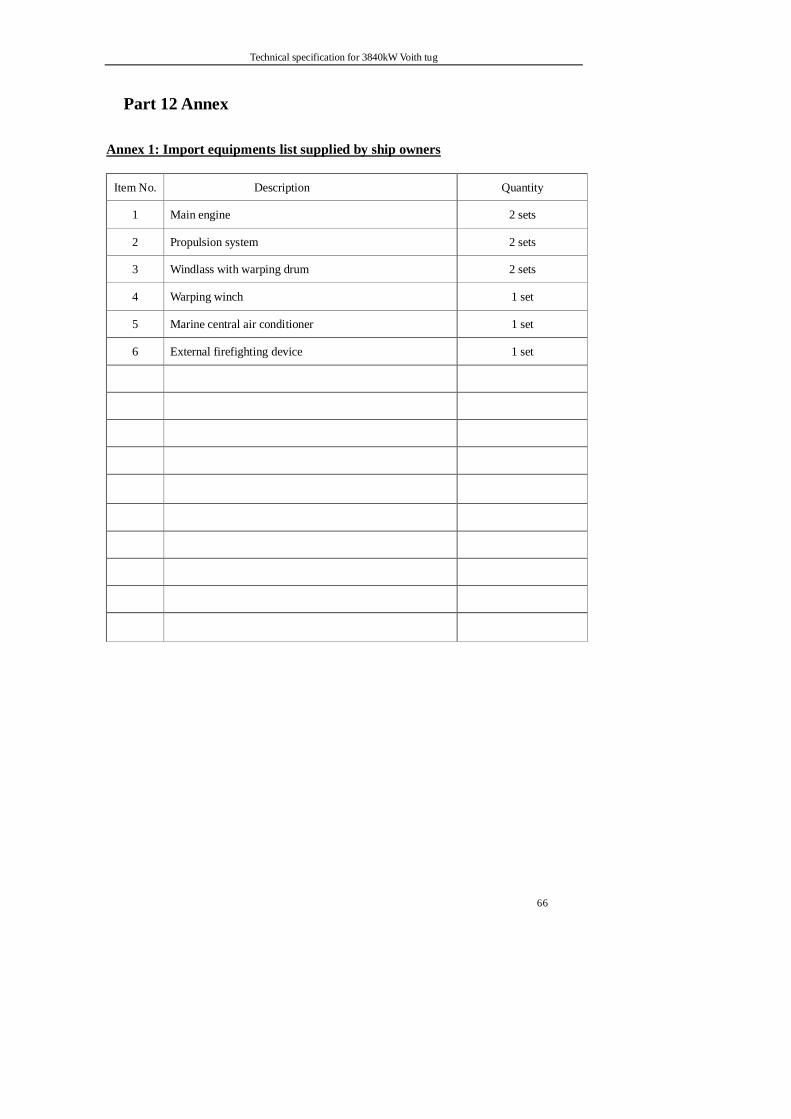
Technical specification for 3840kW Voith tug
66
Part 12 Annex
Annex 1: Import equipments list supplied by ship owners
Item No. Description Quantity
1 Main engine 2 sets
2 Propulsion system 2 sets
3 Windlass with warping drum 2 sets
4 Warping winch 1 set
5 Marine central air conditioner 1 set
6 External firefighting device 1 set
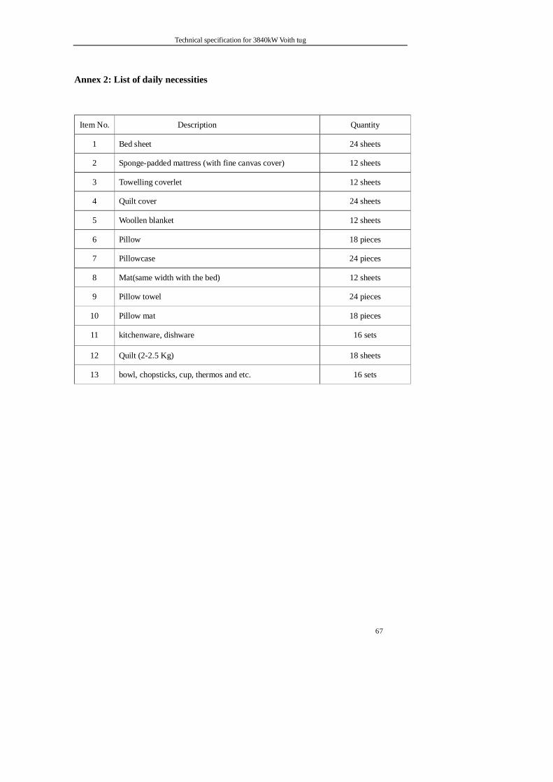
Technical specification for 3840kW Voith tug
67
Annex 2: List of daily necessities
Item No. Description Quantity
1 Bed sheet 24 sheets
2 Sponge-padded mattress (with fine canvas cover) 12 sheets
3 Towelling coverlet 12 sheets
4 Quilt cover 24 sheets
5 Woollen blanket 12 sheets
6 Pillow 18 pieces
7 Pillowcase 24 pieces
8 Mat(same width with the bed) 12 sheets
9 Pillow towel 24 pieces
10 Pillow mat 18 pieces
11 kitchenware, dishware 16 sets
12 Quilt (2-2.5 Kg) 18 sheets
13 bowl, chopsticks, cup, thermos and etc. 16 sets
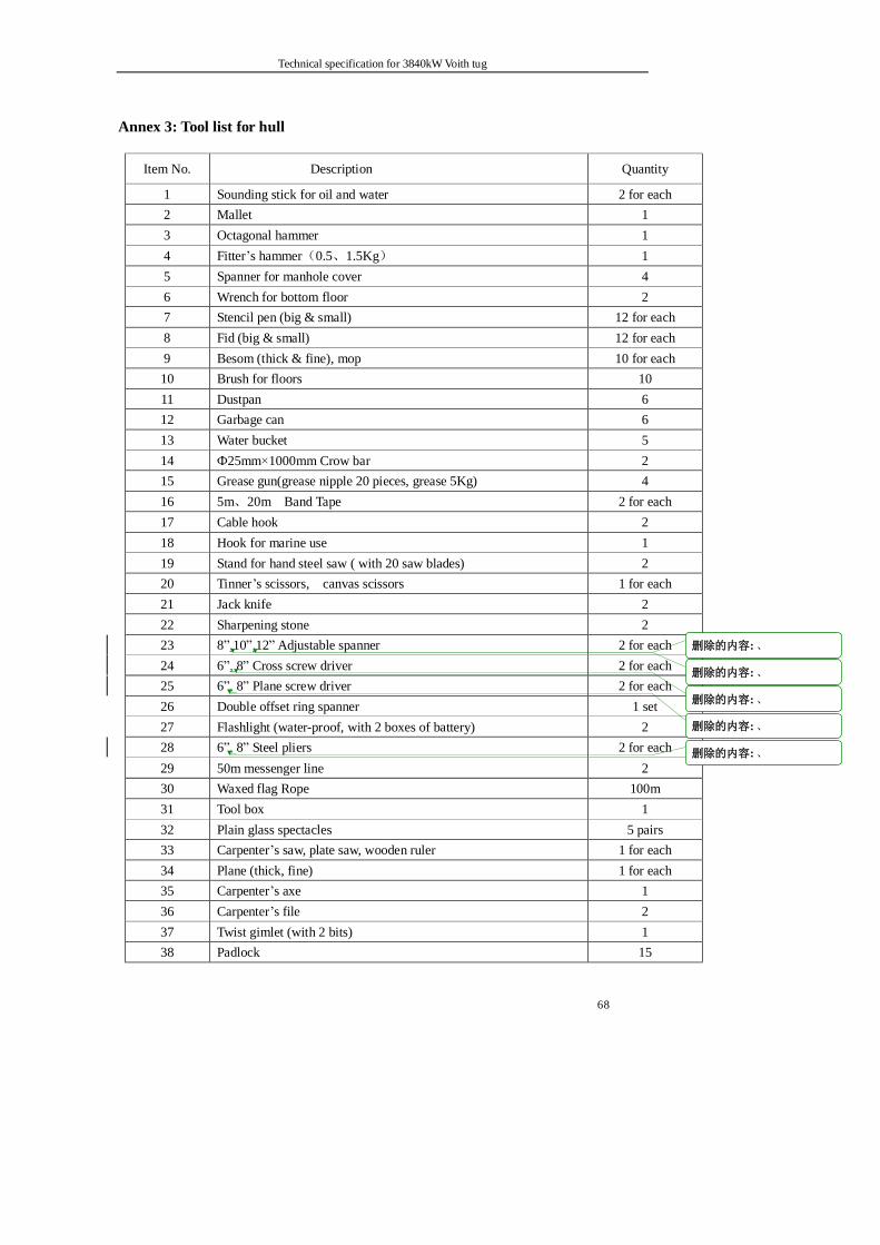
Technical specification for 3840kW Voith tug
68
Annex 3: Tool list for hull
Item No. Description Quantity
1 Sounding stick for oil and water 2 for each 2 Mallet 1 3 Octagonal hammer 1 4 Fitter’s hammer(0.5、1.5Kg) 1 5 Spanner for manhole cover 4 6 Wrench for bottom floor 2 7 Stencil pen (big & small) 12 for each 8 Fid (big & small) 12 for each 9 Besom (thick & fine), mop 10 for each 10 Brush for floors 10 11 Dustpan 6 12 Garbage can 6 13 Water bucket 5 14 Ф25mm×1000mm Crow bar 2 15 Grease gun(grease nipple 20 pieces, grease 5Kg) 4 16 5m、20m Band Tape 2 for each 17 Cable hook 2 18 Hook for marine use 1 19 Stand for hand steel saw ( with 20 saw blades) 2 20 Tinner’s scissors, canvas scissors 1 for each 21 Jack knife 2 22 Sharpening stone 2 23 8”,10”,12” Adjustable spanner 2 for each 24 6”, 8” Cross screw driver 2 for each 25 6”, 8” Plane screw driver 2 for each 26 Double offset ring spanner 1 set 27 Flashlight (water-proof, with 2 boxes of battery) 2 28 6”, 8” Steel pliers 2 for each 29 50m messenger line 2 30 Waxed flag Rope 100m 31 Tool box 1 32 Plain glass spectacles 5 pairs 33 Carpenter’s saw, plate saw, wooden ruler 1 for each 34 Plane (thick, fine) 1 for each 35 Carpenter’s axe 1 36 Carpenter’s file 2 37 Twist gimlet (with 2 bits) 1 38 Padlock 15
删除的内容: 、
删除的内容: 、
删除的内容: 、
删除的内容: 、
删除的内容: 、
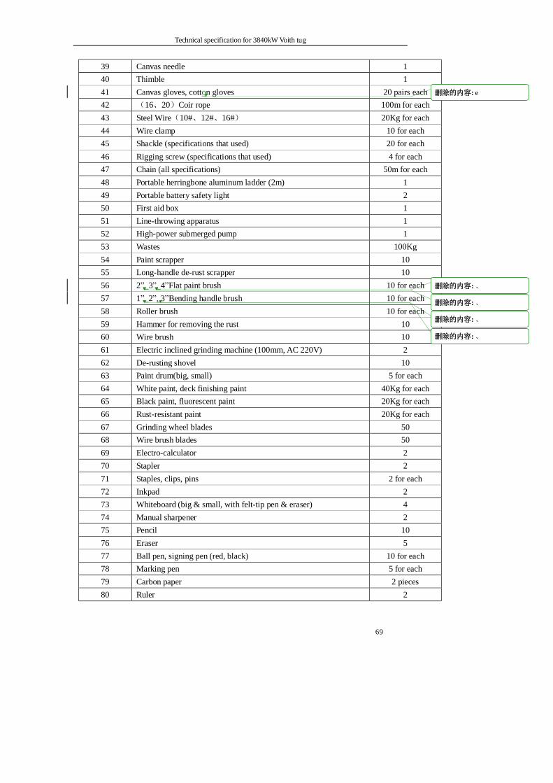
Technical specification for 3840kW Voith tug
69
39 Canvas needle 1 40 Thimble 1 41 Canvas gloves, cotton gloves 20 pairs each 42 (16、20)Coir rope 100m for each 43 Steel Wire(10#、12#、16#) 20Kg for each 44 Wire clamp 10 for each 45 Shackle (specifications that used) 20 for each 46 Rigging screw (specifications that used) 4 for each 47 Chain (all specifications) 50m for each 48 Portable herringbone aluminum ladder (2m) 1 49 Portable battery safety light 2 50 First aid box 1 51 Line-throwing apparatus 1 52 High-power submerged pump 1 53 Wastes 100Kg 54 Paint scrapper 10 55 Long-handle de-rust scrapper 10 56 2”, 3”, 4”Flat paint brush 10 for each 57 1”, 2”, 3”Bending handle brush 10 for each 58 Roller brush 10 for each 59 Hammer for removing the rust 10 60 Wire brush 10 61 Electric inclined grinding machine (100mm, AC 220V) 2 62 De-rusting shovel 10 63 Paint drum(big, small) 5 for each 64 White paint, deck finishing paint 40Kg for each 65 Black paint, fluorescent paint 20Kg for each 66 Rust-resistant paint 20Kg for each 67 Grinding wheel blades 50 68 Wire brush blades 50 69 Electro-calculator 2 70 Stapler 2 71 Staples, clips, pins 2 for each 72 Inkpad 2 73 Whiteboard (big & small, with felt-tip pen & eraser) 4 74 Manual sharpener 2 75 Pencil 10 76 Eraser 5 77 Ball pen, signing pen (red, black) 10 for each 78 Marking pen 5 for each 79 Carbon paper 2 pieces 80 Ruler 2
删除的内容: e
删除的内容: 、
删除的内容: 、
删除的内容: 、
删除的内容: 、
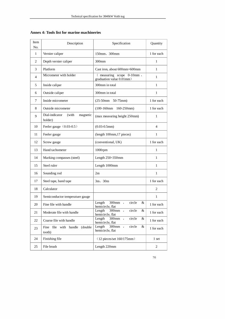
Technical specification for 3840kW Voith tug
70
Annex 4: Tools list for marine machineries
Item No.
Description Specification Quantity
1 Vernier caliper 150mm、300mm 1 for each
2 Depth vernier caliper 300mm 1
3 Platform Cast iron, about 600mm×600mm 1
4 Micrometer with holder ( measuring scope 0-10mm , graduation value 0.01mm) 1
5 Inside caliper 300mm in total 1
6 Outside caliper 300mm in total 1
7 Inside micrometer (25-50mm 50-75mm) 1 for each
8 Outside micrometer (100-160mm 160-250mm) 1 for each
9 Dial-indicator (with magnetic holder)
(max measuring height 250mm) 1
10 Feeler gauge(0.03-0.5) (0.03-0.5mm) 4
11 Feeler gauge (length 100mm,17 pieces) 1
12 Screw gauge (conventional, UK) 1 for each
13 Hand tachometer 1000rpm 1
14 Marking compasses (steel) Length 250×350mm 1
15 Steel ruler Length 1000mm 1
16 Sounding rod 2m 1
17 Steel tape, band tape 3m、30m 1 for each
18 Calculator 2
19 Semiconductor temperature gauge 1
20 Fine file with handle Length 300mm , circle & hemicircle, flat 1 for each
21 Moderate file with handle Length 300mm , circle & hemicircle, flat 1 for each
22 Coarse file with handle Length 300mm , circle & hemicircle, flat 1 for each
23 Fine file with handle (double tooth)
Length 300mm , circle & hemicircle, flat 1 for each
24 Finishing file (12 pieces/set 160/175mm) 1 set
25 File brush Length 220mm 2
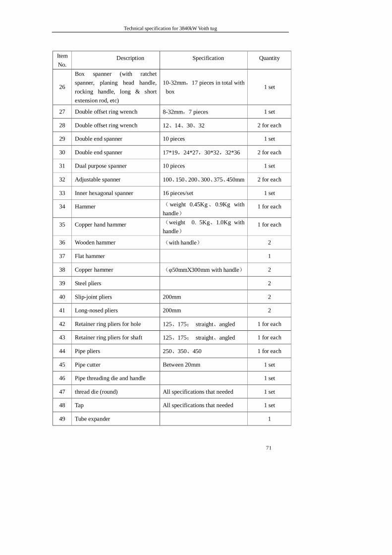
Technical specification for 3840kW Voith tug
71
Item No.
Description Specification Quantity
26
Box spanner (with ratchet spanner, planing head handle, rocking handle, long & short extension rod, etc)
10-32mm,17 pieces in total with box
1 set
27 Double offset ring wrench 8-32mm,7 pieces 1 set
28 Double offset ring wrench 12、14、30、32 2 for each
29 Double end spanner 10 pieces 1 set
30 Double end spanner 17*19,24*27,30*32,32*36 2 for each
31 Dual purpose spanner 10 pieces 1 set
32 Adjustable spanner 100、150、200、300、375、450mm 2 for each
33 Inner hexagonal spanner 16 pieces/set 1 set
34 Hammer (weight 0.45Kg、 0.9Kg with handle)
1 for each
35 Copper hand hammer (weight 0. 5Kg、1.0Kg with handle)
1 for each
36 Wooden hammer (with handle) 2
37 Flat hammer 1
38 Copper hammer (φ50mmΧ300mm with handle) 2
39 Steel pliers 2
40 Slip-joint pliers 200mm 2
41 Long-nosed pliers 200mm 2
42 Retainer ring pliers for hole 125、175; straight、angled 1 for each
43 Retainer ring pliers for shaft 125、175; straight、angled 1 for each
44 Pipe pliers 250、350、450 1 for each
45 Pipe cutter Between 20mm 1 set
46 Pipe threading die and handle 1 set
47 thread die (round) All specifications that needed 1 set
48 Tap All specifications that needed 1 set
49 Tube expander 1
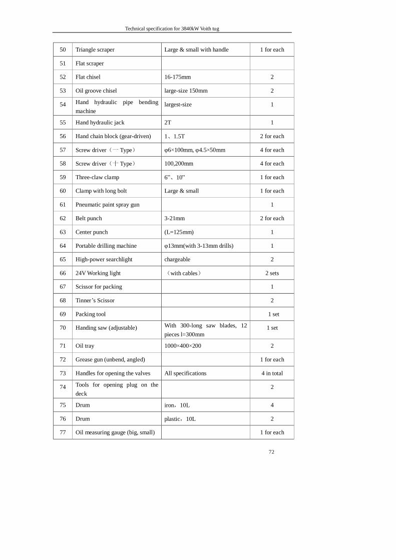
Technical specification for 3840kW Voith tug
72
50 Triangle scraper Large & small with handle 1 for each
51 Flat scraper
52 Flat chisel 16-175mm 2
53 Oil groove chisel large-size 150mm 2
54 Hand hydraulic pipe bending machine
largest-size 1
55 Hand hydraulic jack 2T 1
56 Hand chain block (gear-driven) 1、1.5T 2 for each
57 Screw driver(一 Type) φ6×100mm, φ4.5×50mm 4 for each
58 Screw driver(十 Type) 100,200mm 4 for each
59 Three-claw clamp 6”、10” 1 for each
60 Clamp with long bolt Large & small 1 for each
61 Pneumatic paint spray gun 1
62 Belt punch 3-21mm 2 for each
63 Center punch (L=125mm) 1
64 Portable drilling machine φ13mm(with 3-13mm drills) 1
65 High-power searchlight chargeable 2
66 24V Working light (with cables) 2 sets
67 Scissor for packing 1
68 Tinner’s Scissor 2
69 Packing tool 1 set
70 Handing saw (adjustable) With 300-long saw blades, 12 pieces l=300mm
1 set
71 Oil tray 1000×400×200 2
72 Grease gun (unbend, angled) 1 for each
73 Handles for opening the valves All specifications 4 in total
74 Tools for opening plug on the deck
2
75 Drum iron,10L 4
76 Drum plastic,10L 2
77 Oil measuring gauge (big, small) 1 for each
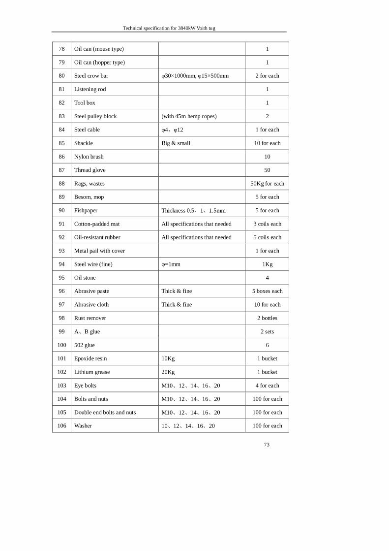
Technical specification for 3840kW Voith tug
73
78 Oil can (mouse type) 1
79 Oil can (hopper type) 1
80 Steel crow bar φ30×1000mm, φ15×500mm 2 for each
81 Listening rod 1
82 Tool box 1
83 Steel pulley block (with 45m hemp ropes) 2
84 Steel cable φ4,φ12 1 for each
85 Shackle Big & small 10 for each
86 Nylon brush 10
87 Thread glove 50
88 Rags, wastes 50Kg for each
89 Besom, mop 5 for each
90 Fishpaper Thickness 0.5、1、1.5mm 5 for each
91 Cotton-padded mat All specifications that needed 3 coils each
92 Oil-resistant rubber All specifications that needed 5 coils each
93 Metal pail with cover 1 for each
94 Steel wire (fine) φ=1mm 1Kg
95 Oil stone 4
96 Abrasive paste Thick & fine 5 boxes each
97 Abrasive cloth Thick & fine 10 for each
98 Rust remover 2 bottles
99 A、B glue 2 sets
100 502 glue 6
101 Epoxide resin 10Kg 1 bucket
102 Lithium grease 20Kg 1 bucket
103 Eye bolts M10、12、14、16、20 4 for each
104 Bolts and nuts M10、12、14、16、20 100 for each
105 Double end bolts and nuts M10、12、14、16、20 100 for each
106 Washer 10、12、14、16、20 100 for each
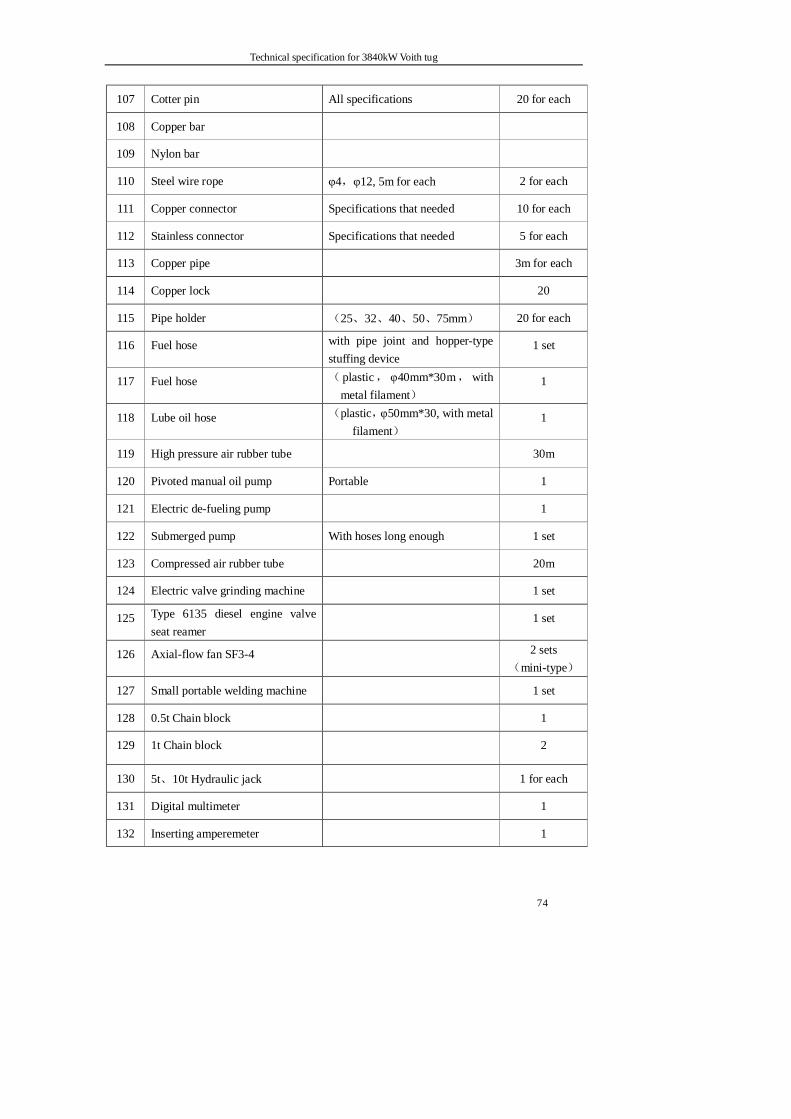
Technical specification for 3840kW Voith tug
74
107 Cotter pin All specifications 20 for each
108 Copper bar
109 Nylon bar
110 Steel wire rope φ4,φ12, 5m for each 2 for each
111 Copper connector Specifications that needed 10 for each
112 Stainless connector Specifications that needed 5 for each
113 Copper pipe 3m for each
114 Copper lock 20
115 Pipe holder (25、32、40、50、75mm) 20 for each
116 Fuel hose with pipe joint and hopper-type stuffing device
1 set
117 Fuel hose ( plastic, φ40mm*30m,with metal filament)
1
118 Lube oil hose (plastic,φ50mm*30, with metal filament)
1
119 High pressure air rubber tube 30m
120 Pivoted manual oil pump Portable 1
121 Electric de-fueling pump 1
122 Submerged pump With hoses long enough 1 set
123 Compressed air rubber tube 20m
124 Electric valve grinding machine 1 set
125 Type 6135 diesel engine valve seat reamer
1 set
126 Axial-flow fan SF3-4 2 sets(mini-type)
127 Small portable welding machine 1 set
128 0.5t Chain block 1
129 1t Chain block 2
130 5t、10t Hydraulic jack 1 for each
131 Digital multimeter 1
132 Inserting amperemeter 1
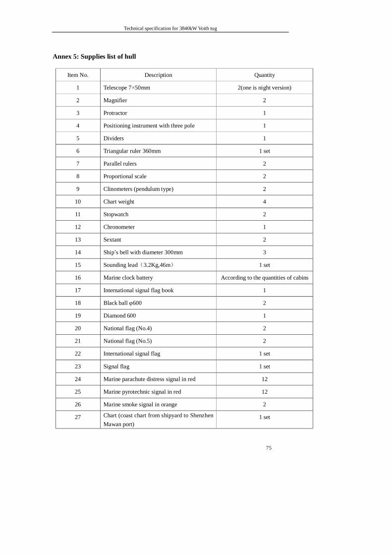
Technical specification for 3840kW Voith tug
75
Annex 5: Supplies list of hull
Item No. Description Quantity
1 Telescope 7×50mm 2(one is night version)
2 Magnifier 2
3 Protractor 1
4 Positioning instrument with three pole 1
5 Dividers 1
6 Triangular ruler 360mm 1 set
7 Parallel rulers 2
8 Proportional scale 2
9 Clinometers (pendulum type) 2
10 Chart weight 4
11 Stopwatch 2
12 Chronometer 1
13 Sextant 2
14 Ship’s bell with diameter 300mm 3
15 Sounding lead(3.2Kg,46m) 1 set
16 Marine clock battery According to the quantities of cabins
17 International signal flag book 1
18 Black ball φ600 2
19 Diamond 600 1
20 National flag (No.4) 2
21 National flag (No.5) 2
22 International signal flag 1 set
23 Signal flag 1 set
24 Marine parachute distress signal in red 12
25 Marine pyrotechnic signal in red 12
26 Marine smoke signal in orange 2
27 Chart (coast chart from shipyard to Shenzhen Mawan port)
1 set
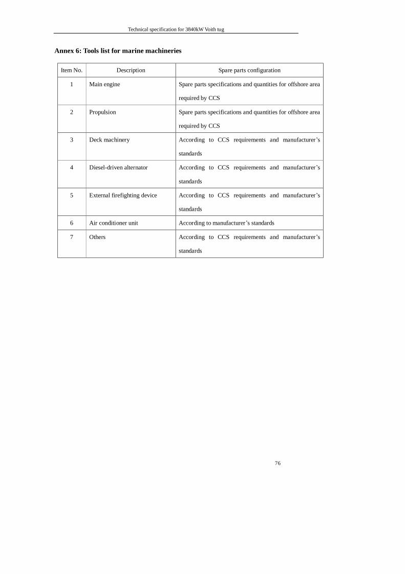
Technical specification for 3840kW Voith tug
76
Annex 6: Tools list for marine machineries
Item No. Description Spare parts configuration
1 Main engine Spare parts specifications and quantities for offshore area
required by CCS
2 Propulsion Spare parts specifications and quantities for offshore area
required by CCS
3 Deck machinery According to CCS requirements and manufacturer’s
standards
4 Diesel-driven alternator According to CCS requirements and manufacturer’s
standards
5 External firefighting device According to CCS requirements and manufacturer’s
standards
6 Air conditioner unit According to manufacturer’s standards
7 Others According to CCS requirements and manufacturer’s
standards
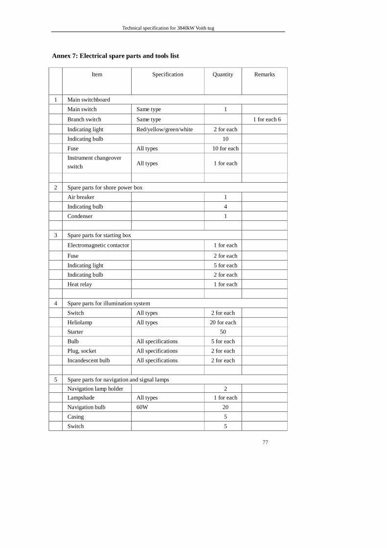
Technical specification for 3840kW Voith tug
77
Annex 7: Electrical spare parts and tools list
Item Specification Quantity Remarks
1 Main switchboard Main switch Same type 1
Branch switch Same type 1 for each 6
Indicating light Red/yellow/green/white 2 for each Indicating bulb 10 Fuse All types 10 for each
Instrument changeover switch
All types 1 for each
2 Spare parts for shore power box Air breaker 1 Indicating bulb 4 Condenser 1 3 Spare parts for starting box
Electromagnetic contactor 1 for each
Fuse 2 for each Indicating light 5 for each Indicating bulb 2 for each Heat relay 1 for each 4 Spare parts for illumination system Switch All types 2 for each Heliolamp All types 20 for each Starter 50 Bulb All specifications 5 for each Plug, socket All specifications 2 for each Incandescent bulb All specifications 2 for each 5 Spare parts for navigation and signal lamps Navigation lamp holder 2 Lampshade All types 1 for each Navigation bulb 60W 20 Casing 5 Switch 5
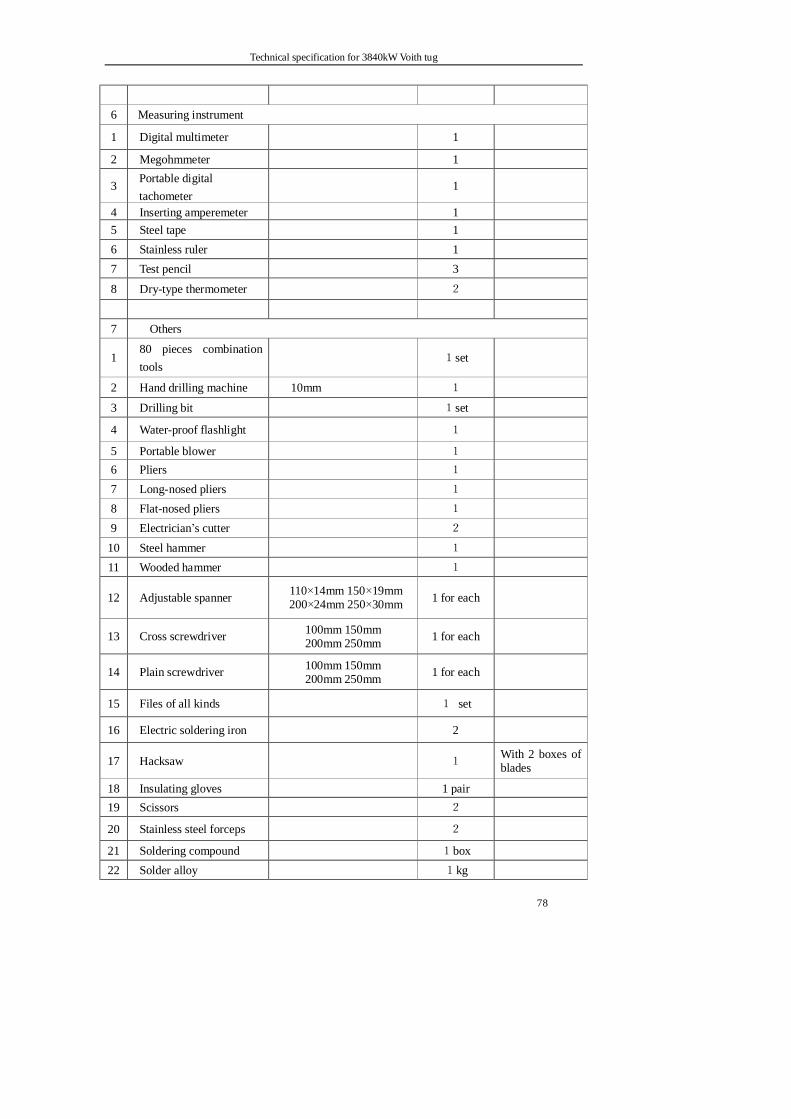
Technical specification for 3840kW Voith tug
78
6 Measuring instrument
1 Digital multimeter 1
2 Megohmmeter 1
3 Portable digital tachometer
1
4 Inserting amperemeter 1 5 Steel tape 1 6 Stainless ruler 1 7 Test pencil 3
8 Dry-type thermometer 2
7 Others
1 80 pieces combination tools
1set
2 Hand drilling machine 10mm 1
3 Drilling bit 1set
4 Water-proof flashlight 1
5 Portable blower 1 6 Pliers 1 7 Long-nosed pliers 1 8 Flat-nosed pliers 1 9 Electrician’s cutter 2
10 Steel hammer 1 11 Wooded hammer 1
12 Adjustable spanner 110×14mm 150×19mm 200×24mm 250×30mm 1 for each
13 Cross screwdriver 100mm 150mm 200mm 250mm 1 for each
14 Plain screwdriver 100mm 150mm 200mm 250mm 1 for each
15 Files of all kinds 1 set
16 Electric soldering iron 2
17 Hacksaw 1 With 2 boxes of blades
18 Insulating gloves 1 pair 19 Scissors 2
20 Stainless steel forceps 2
21 Soldering compound 1box 22 Solder alloy 1kg

Technical specification for 3840kW Voith tug
79
23 Polyvinyl chloride (PVC) insulation strap 4coil
24 Cold-pressed connecting pliers
400mm 1