Embed Size (px)
Citation preview
3A2798FEN
Instructions - Parts
Xtreme® PFPFor use with bulk supply of medium to high viscosity sealants and adhesive materials. For professional use only.
Model 16T3115 gallon (20 liter), NXT® air motor, with cart
6500 psi (45 MPa, 448 bar) Maximum Fluid Working Pressure90 psi (620 kPa, 6.2 bar) Maximum Air Working Pressure100 psi (0.7 kPa, 7 bar) Maximum Air Inlet Pressure
Model 16P9575 gallon (20 liter), NXT® air motor, no cart
6500 psi (45 MPa, 448 bar) Maximum Fluid Working Pressure90 psi (620 kPa, 6.2 bar) Maximum Air Working Pressure100 psi (0.7 kPa, 7 bar) Maximum Air Inlet Pressure
Model 24X0695 gallon (20 liter), Xtreme® XL air motor, with cart
7250 psi (50 MPa, 500 bar) Maximum Fluid Working Pressure100 psi (0.7 kPa, 7 bar) Maximum Air Working Pressure100 psi (0.7 kPa, 7 bar) Maximum Air Inlet Pressure
Model 24X0685 gallon (20 liter), Xtreme® XL air motor, no cart
7250 psi (50 MPa, 500 bar) Maximum Fluid Working Pressure100 psi (0.7 kPa, 7 bar) Maximum Air Working Pressure100 psi (0.7 kPa, 7 bar) Maximum Air Inlet Pressure
Important Safety InstructionsRead all warnings and instructions in this man-ual. Save these instructions.
Model 16T311 shown
Model 24X069 shown
II 2 G c T2
Related Manuals
2 3A2798F
ContentsRelated Manuals . . . . . . . . . . . . . . . . . . . . . . . . . . . 2Warnings . . . . . . . . . . . . . . . . . . . . . . . . . . . . . . . . . 3Component Identification . . . . . . . . . . . . . . . . . . . . 5Installation . . . . . . . . . . . . . . . . . . . . . . . . . . . . . . . . 8
General Information . . . . . . . . . . . . . . . . . . . . . . 8Location . . . . . . . . . . . . . . . . . . . . . . . . . . . . . . . 8Grounding . . . . . . . . . . . . . . . . . . . . . . . . . . . . . . 8Connect Mix Line and Gun . . . . . . . . . . . . . . . . . 9Mechanical Setup . . . . . . . . . . . . . . . . . . . . . . . . 9Attach Drum Stops . . . . . . . . . . . . . . . . . . . . . . . 9
Supply System Operation . . . . . . . . . . . . . . . . . . . 10Before Operating . . . . . . . . . . . . . . . . . . . . . . . . 10Pressure Relief Procedure . . . . . . . . . . . . . . . . 10Flush Before Using Equipment . . . . . . . . . . . . . 10Start and Adjust Ram . . . . . . . . . . . . . . . . . . . . 10Start and Adjust Pump . . . . . . . . . . . . . . . . . . . 11Change Drums . . . . . . . . . . . . . . . . . . . . . . . . . 11Flush . . . . . . . . . . . . . . . . . . . . . . . . . . . . . . . . . 12Shutdown and Care of the Pump . . . . . . . . . . . 12Replace Throat Seals . . . . . . . . . . . . . . . . . . . . 12Remove Quick Coupler . . . . . . . . . . . . . . . . . . . 12
Before Beginning Repair . . . . . . . . . . . . . . . . . . . 13Maintenance Procedures . . . . . . . . . . . . . . . . . . . 13
Platen Maintenance . . . . . . . . . . . . . . . . . . . . . 13Adjust Spacers . . . . . . . . . . . . . . . . . . . . . . . . . 13Remove and Reinstall Wiper . . . . . . . . . . . . . . 14
Troubleshooting . . . . . . . . . . . . . . . . . . . . . . . . . . . 16Repair . . . . . . . . . . . . . . . . . . . . . . . . . . . . . . . . . . . 17
Disconnect Pump from Platen . . . . . . . . . . . . . . 17Connect Platen to Pump . . . . . . . . . . . . . . . . . . 17Remove Wipers . . . . . . . . . . . . . . . . . . . . . . . . . 17Install Wipers . . . . . . . . . . . . . . . . . . . . . . . . . . . 17Disconnect Displacement Pump . . . . . . . . . . . . 18Remove Displacement Pump . . . . . . . . . . . . . . 18Install Displacement Pump . . . . . . . . . . . . . . . . 18Connect Displacement Pump . . . . . . . . . . . . . . 18Remove Air Motor . . . . . . . . . . . . . . . . . . . . . . . 19Install Air Motor . . . . . . . . . . . . . . . . . . . . . . . . . 19Supply Unit Repair . . . . . . . . . . . . . . . . . . . . . . . 20
Parts . . . . . . . . . . . . . . . . . . . . . . . . . . . . . . . . . . . . 22Check Valve (16T481) . . . . . . . . . . . . . . . . . . . . 30
Accessories . . . . . . . . . . . . . . . . . . . . . . . . . . . . . . 31Static Mixer Kit, 16T316 . . . . . . . . . . . . . . . . . . 31Static Mixer (16T316) . . . . . . . . . . . . . . . . . . . . 31
Dimensions . . . . . . . . . . . . . . . . . . . . . . . . . . . . . . . 32Technical Data . . . . . . . . . . . . . . . . . . . . . . . . . . . . 33Graco Standard Warranty . . . . . . . . . . . . . . . . . . . 34Graco Information . . . . . . . . . . . . . . . . . . . . . . . . . 34
Related ManualsThe following manuals are available at www.graco.com. Component Manuals in English:
Manual Description
311762 Xtreme Lowers Instructions-Parts
311238 NXT® Air Motor Instructions-Parts
334644 Xtreme XL Air Motor Instructions-Parts
Warnings
3A2798F 3
WarningsThe following warnings are for the setup, use, grounding, maintenance, and repair of this equipment. The exclama-tion point symbol alerts you to a general warning and the hazard symbols refer to procedure-specific risks. When these symbols appear in the body of this manual or on warning labels, refer back to these Warnings. Product-specific hazard symbols and warnings not covered in this section may appear throughout the body of this manual where applicable.
WARNINGSKIN INJECTION HAZARDHigh-pressure fluid from gun, hose leaks, or ruptured components will pierce skin. This may look like just a cut, but it is a serious injury that can result in amputation. Get immediate surgical treatment.• Do not spray without tip guard and trigger guard installed.• Engage trigger lock when not spraying.• Do not point gun at anyone or at any part of the body.• Do not put your hand over the spray tip.• Do not stop or deflect leaks with your hand, body, glove, or rag.• Follow the Pressure Relief Procedure when you stop spraying and before cleaning, checking, or
servicing equipment. • Tighten all fluid connections before operating the equipment.• Check hoses and couplings daily. Replace worn or damaged parts immediately.
MOVING PARTS HAZARDMoving parts can pinch, cut or amputate fingers and other body parts.• Keep clear of moving parts.• Do not operate equipment with protective guards or covers removed.• Pressurized equipment can start without warning. Before checking, moving, or servicing equipment,
follow the Pressure Relief Procedure and disconnect all power sources.
FIRE AND EXPLOSION HAZARDFlammable fumes, such as solvent and paint fumes, in work area can ignite or explode. To help prevent fire and explosion:• Use equipment only in well ventilated area.• Eliminate all ignition sources; such as pilot lights, cigarettes, portable electric lamps, and plastic drop
cloths (potential static arc). • Keep work area free of debris, including solvent, rags and gasoline.• Do not plug or unplug power cords, or turn power or light switches on or off when flammable fumes
are present.• Ground all equipment in the work area. See Grounding instructions.• Use only grounded hoses.• Hold gun firmly to side of grounded pail when triggering into pail. Do not use pail liners unless they
are antistatic or conductive.• Stop operation immediately if static sparking occurs or you feel a shock. Do not use equipment
until you identify and correct the problem.• Keep a working fire extinguisher in the work area.
Warnings
4 3A2798F
EQUIPMENT MISUSE HAZARDMisuse can cause death or serious injury.• Do not operate the unit when fatigued or under the influence of drugs or alcohol.• Do not exceed the maximum working pressure or temperature rating of the lowest rated system
component. See Technical Data in all equipment manuals.• Use fluids and solvents that are compatible with equipment wetted parts. See Technical Data in all
equipment manuals. Read fluid and solvent manufacturer’s warnings. For complete information about your material, request MSDS from distributor or retailer.
• Do not leave the work area while equipment is energized or under pressure.• Turn off all equipment and follow the Pressure Relief Procedure when equipment is not in use.• Check equipment daily. Repair or replace worn or damaged parts immediately with genuine manu-
facturer’s replacement parts only.• Do not alter or modify equipment. Alterations or modifications may void agency approvals and create
safety hazards.• Make sure all equipment is rated and approved for the environment in which you are using it.• Use equipment only for its intended purpose. Call your distributor for information.• Route hoses and cables away from traffic areas, sharp edges, moving parts, and hot surfaces.• Do not kink or over bend hoses or use hoses to pull equipment.• Keep children and animals away from work area.• Comply with all applicable safety regulations.
SPLATTER HAZARD Hot or toxic fluid can cause serious injury if splashed in the eyes or on skin. During blow off of platen, splatter may occur. • Use minimum air pressure when removing platen from drum.
TOXIC FLUID OR FUMES HAZARDToxic fluids or fumes can cause serious injury or death if splashed in the eyes or on skin, inhaled, or swallowed.• Read MSDSs to know the specific hazards of the fluids you are using.• Store hazardous fluid in approved containers, and dispose of it according to applicable guidelines.
PERSONAL PROTECTIVE EQUIPMENTWear appropriate protective equipment when in the work area to help prevent serious injury, including eye injury, hearing loss, inhalation of toxic fumes, and burns. This protective equipment includes but is not limited to:• Protective eyewear, and hearing protection. • Respirators, protective clothing, and gloves as recommended by the fluid and solvent manufacturer
WARNING
Component Identification
3A2798F 5
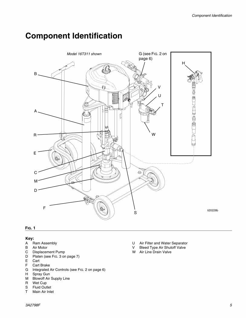
Component Identification
Key:A Ram AssemblyB Air MotorC Displacement PumpD Platen (see FIG. 3 on page 7)E CartF Cart BrakeG Integrated Air Controls (see FIG. 2 on page 6)H Spray GunM Blowoff Air Supply LineR Wet CupS Fluid OutletT Main Air Inlet
U Air Filter and Water SeparatorV Bleed Type Air Shutoff ValveW Air Line Drain Valve
FIG. 1
Model 16T311 shown
H
FS
T
U
A
E
B
C
D
M
R
V
G (see FIG. 2 on page 6)
ti20228b
W
Component Identification
6 3A2798F
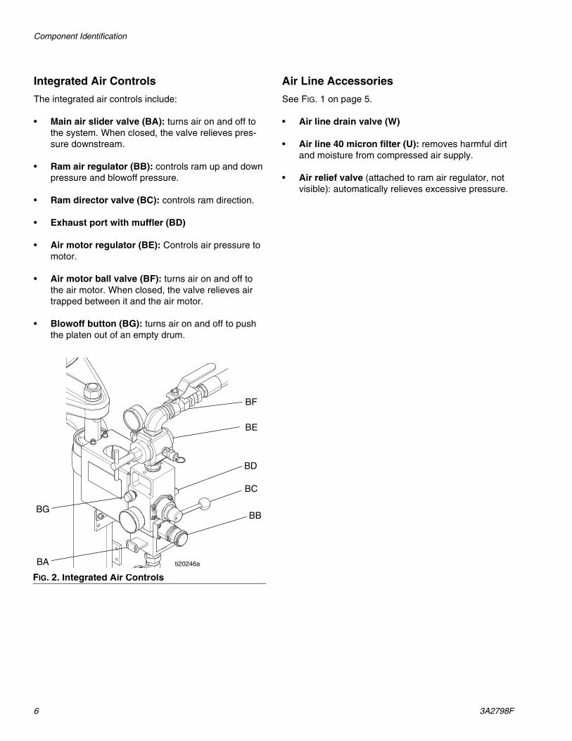
Integrated Air Controls
The integrated air controls include:
• Main air slider valve (BA): turns air on and off to the system. When closed, the valve relieves pres-sure downstream.
• Ram air regulator (BB): controls ram up and down pressure and blowoff pressure.
• Ram director valve (BC): controls ram direction.
• Exhaust port with muffler (BD)
• Air motor regulator (BE): Controls air pressure to motor.
• Air motor ball valve (BF): turns air on and off to the air motor. When closed, the valve relieves air trapped between it and the air motor.
• Blowoff button (BG): turns air on and off to push the platen out of an empty drum.
Air Line Accessories
See FIG. 1 on page 5.
• Air line drain valve (W)
• Air line 40 micron filter (U): removes harmful dirt and moisture from compressed air supply.
• Air relief valve (attached to ram air regulator, not visible): automatically relieves excessive pressure.
FIG. 2. Integrated Air Controls
BA
BB
BC
BG
BE
BF
BD
ti20246a
Component Identification
3A2798F 7
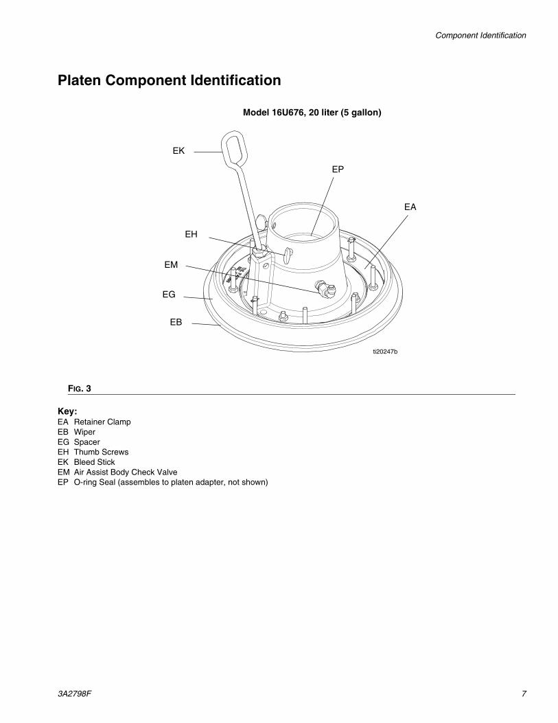
Platen Component Identification
Key:EA Retainer ClampEB WiperEG SpacerEH Thumb ScrewsEK Bleed StickEM Air Assist Body Check ValveEP O-ring Seal (assembles to platen adapter, not shown)
FIG. 3
ti20247b
EH
EG
EB
EK
Model 16U676, 20 liter (5 gallon)
EM
EA
EP
Installation
8 3A2798F
Installation
General InformationNOTE: Reference numbers and letters in parentheses in the text refer to the callouts in the figures.
Accessories are available from Graco. Make certain all accessories are adequately sized and pressure-rated to meet the system’s requirements.
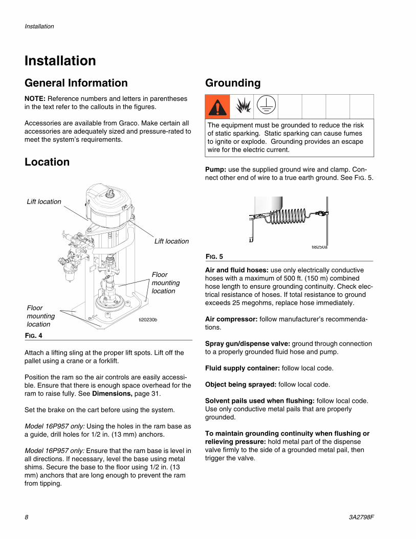
Location
Attach a lifting sling at the proper lift spots. Lift off the pallet using a crane or a forklift.
Position the ram so the air controls are easily accessi-ble. Ensure that there is enough space overhead for the ram to raise fully. See Dimensions, page 31.
Set the brake on the cart before using the system.
Model 16P957 only: Using the holes in the ram base as a guide, drill holes for 1/2 in. (13 mm) anchors.
Model 16P957 only: Ensure that the ram base is level in all directions. If necessary, level the base using metal shims. Secure the base to the floor using 1/2 in. (13 mm) anchors that are long enough to prevent the ram from tipping.
Grounding
Pump: use the supplied ground wire and clamp. Con-nect other end of wire to a true earth ground. See FIG. 5.
Air and fluid hoses: use only electrically conductive hoses with a maximum of 500 ft. (150 m) combined hose length to ensure grounding continuity. Check elec-trical resistance of hoses. If total resistance to ground exceeds 25 megohms, replace hose immediately.
Air compressor: follow manufacturer’s recommenda-tions.
Spray gun/dispense valve: ground through connection to a properly grounded fluid hose and pump.
Fluid supply container: follow local code.
Object being sprayed: follow local code.
Solvent pails used when flushing: follow local code. Use only conductive metal pails that are properly grounded.
To maintain grounding continuity when flushing or relieving pressure: hold metal part of the dispense valve firmly to the side of a grounded metal pail, then trigger the valve.
FIG. 4
ti20230b
Lift location
Lift location
Floor mounting location
Floor mounting location
The equipment must be grounded to reduce the risk of static sparking. Static sparking can cause fumes to ignite or explode. Grounding provides an escape wire for the electric current.
FIG. 5
ti8250a
Installation
3A2798F 9
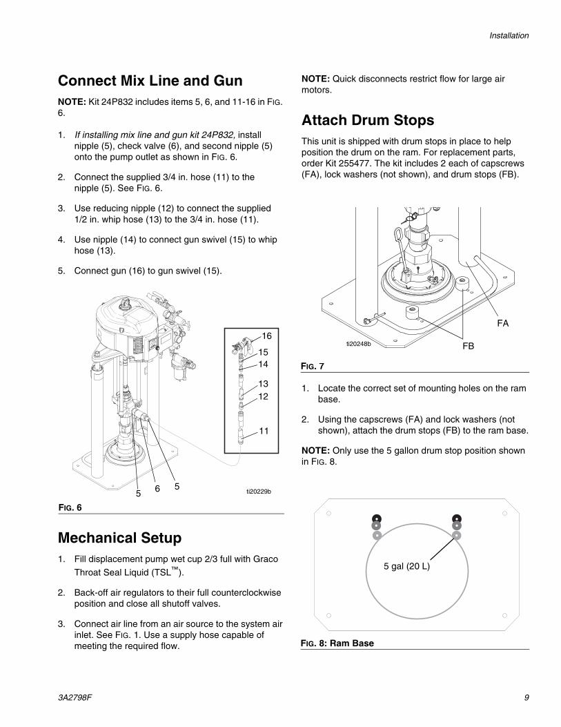
Connect Mix Line and GunNOTE: Kit 24P832 includes items 5, 6, and 11-16 in FIG. 6.
1. If installing mix line and gun kit 24P832, install nipple (5), check valve (6), and second nipple (5) onto the pump outlet as shown in FIG. 6.
2. Connect the supplied 3/4 in. hose (11) to the nipple (5). See FIG. 6.
3. Use reducing nipple (12) to connect the supplied 1/2 in. whip hose (13) to the 3/4 in. hose (11).
4. Use nipple (14) to connect gun swivel (15) to whip hose (13).
5. Connect gun (16) to gun swivel (15).
Mechanical Setup1. Fill displacement pump wet cup 2/3 full with Graco
Throat Seal Liquid (TSL™).
2. Back-off air regulators to their full counterclockwise position and close all shutoff valves.
3. Connect air line from an air source to the system air inlet. See FIG. 1. Use a supply hose capable of meeting the required flow.
NOTE: Quick disconnects restrict flow for large air motors.
Attach Drum StopsThis unit is shipped with drum stops in place to help position the drum on the ram. For replacement parts, order Kit 255477. The kit includes 2 each of capscrews (FA), lock washers (not shown), and drum stops (FB).
1. Locate the correct set of mounting holes on the ram base.
2. Using the capscrews (FA) and lock washers (not shown), attach the drum stops (FB) to the ram base.
NOTE: Only use the 5 gallon drum stop position shown in FIG. 8.
FIG. 6
ti20229b5
11
1213
16
15
5
14
6
FIG. 7
FIG. 8: Ram Base
FA
FBti20248b
5 gal (20 L)
Supply System Operation
10 3A2798F
Supply System Operation
Before Operating
Pressure Relief ProcedureFollow the Pressure Relief Procedure whenever you see this symbol.
1. Lock the gun/valve trigger.
2. See FIG. 2, page 6.
a. Close the air motor ball valve (BF) and the main air slider valve (BA).
b. If the RAM is in a raised position, set the ram director valve (BC) to DOWN. The ram will slowly drop.
c. Jog the director valve up and down to bleed air from ram cylinders.
3. Unlock the gun/valve trigger.
4. Hold a metal part of the gun/valve firmly to the side of a grounded metal pail, and trigger the gun/valve to relieve pressure.
5. Lock the gun/valve trigger.
If you suspect that the spray tip/nozzle or hose is com-pletely clogged, or that pressure has not been fully relieved after following the steps above, very slowly loosen the tip guard retaining nut or hose end coupling and relieve pressure gradually, then loosen completely. Now clear the tip/nozzle or hose.
Flush Before Using EquipmentThe pump was tested with lightweight oil, which is left in the fluid passages to protect parts. To avoid contaminat-ing fluid with oil, flush the pump with a compatible sol-vent before use. See Flush on page 12.
Start and Adjust Ram
1. Set platen configuration based on pail type (see Adjust Spacers, page 13).
2. Refer to FIG. 1 and FIG. 2. Close all air regulators and air valves.
3. Open main air slider valve (BA) and set ram air reg-ulator (BB) to 45 psi (0.31 MPa, 3.1 bar). Set direc-tor valve handle (BC) to UP and let the ram rise to its full height.
4. Remove the drum cover.
NOTICE
To prevent mixed material from fully curing in the system requiring replacement of all parts containing cured material, always be prepared to immediately begin flushing at the first sign of material curing in the system and immediately after spraying stops. See Flush on page 12.
This equipment stays pressurized until pressure is manually relieved. To help prevent serious injury from pressurized fluid, such as skin injection, splashing fluid and moving parts, follow the Pressure Relief Procedure when you stop spraying and before cleaning, checking, or servicing the equipment.
NOTICE
Prolonged exposure to solvent will reduce the life of the wiper. For maximum performance, do NOT soak platen soft parts in solvent. Instead, gently wipe down soft parts with solvent.
Moving parts can pinch or amputate fingers. When the pump is operating and when raising or lowering the ram, keep fingers and hands away from the pump intake, platen, and lip of the drum.
Supply System Operation
3A2798F 11
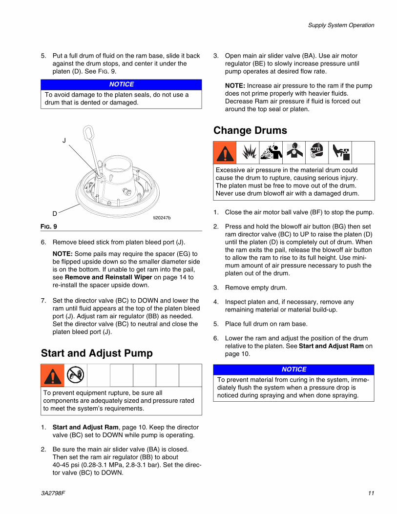
5. Put a full drum of fluid on the ram base, slide it back against the drum stops, and center it under the platen (D). See FIG. 9.
6. Remove bleed stick from platen bleed port (J).
NOTE: Some pails may require the spacer (EG) to be flipped upside down so the smaller diameter side is on the bottom. If unable to get ram into the pail, see Remove and Reinstall Wiper on page 14 to re-install the spacer upside down.
7. Set the director valve (BC) to DOWN and lower the ram until fluid appears at the top of the platen bleed port (J). Adjust ram air regulator (BB) as needed. Set the director valve (BC) to neutral and close the platen bleed port (J).
Start and Adjust Pump
1. Start and Adjust Ram, page 10. Keep the director valve (BC) set to DOWN while pump is operating.
2. Be sure the main air slider valve (BA) is closed. Then set the ram air regulator (BB) to about 40-45 psi (0.28-3.1 MPa, 2.8-3.1 bar). Set the direc-tor valve (BC) to DOWN.
3. Open main air slider valve (BA). Use air motor regulator (BE) to slowly increase pressure until pump operates at desired flow rate.
NOTE: Increase air pressure to the ram if the pump does not prime properly with heavier fluids. Decrease Ram air pressure if fluid is forced out around the top seal or platen.
Change Drums
1. Close the air motor ball valve (BF) to stop the pump.
2. Press and hold the blowoff air button (BG) then set ram director valve (BC) to UP to raise the platen (D) until the platen (D) is completely out of drum. When the ram exits the pail, release the blowoff air button to allow the ram to rise to its full height. Use mini-mum amount of air pressure necessary to push the platen out of the drum.
3. Remove empty drum.
4. Inspect platen and, if necessary, remove any remaining material or material build-up.
5. Place full drum on ram base.
6. Lower the ram and adjust the position of the drum relative to the platen. See Start and Adjust Ram on page 10.
NOTICE
To avoid damage to the platen seals, do not use a drum that is dented or damaged.
FIG. 9
To prevent equipment rupture, be sure all components are adequately sized and pressure rated to meet the system’s requirements.
J
Dti20247b
Excessive air pressure in the material drum could cause the drum to rupture, causing serious injury. The platen must be free to move out of the drum. Never use drum blowoff air with a damaged drum.
NOTICE
To prevent material from curing in the system, imme-diately flush the system when a pressure drop is noticed during spraying and when done spraying.
Supply System Operation
12 3A2798F
Flush
1. Remove platen from pump, then submerge pump into solvent. To clean platen, gently wipe with sol-vent. NOTE: Read notice table in Flush Before Using Equipment section, page 10.
2. Perform Start and Adjust Ram on page 10 to pres-surize the pump with solvent.
3. Hold gun firmly against a grounded pail and trigger gun into pail until clean solvent dispenses.
Shutdown and Care of the Pump1. Set the ram director valve (BC) to DOWN.
2. Follow the Pressure Relief Procedure on page 10.
3. Follow the pump shutdown instructions in Xtreme lowers manual. See Related Manuals on page 2.
Replace Throat Seals
Remove wet cup from displacement pump while attached to the ram to replace throat seals.
1. Follow the Pressure Relief Procedure on page 10.
2. Remove Quick Coupler.
3. Remove wet cup and packing cartridge according to instructions in Xtreme lowers manual. See Related Manuals on page 2.
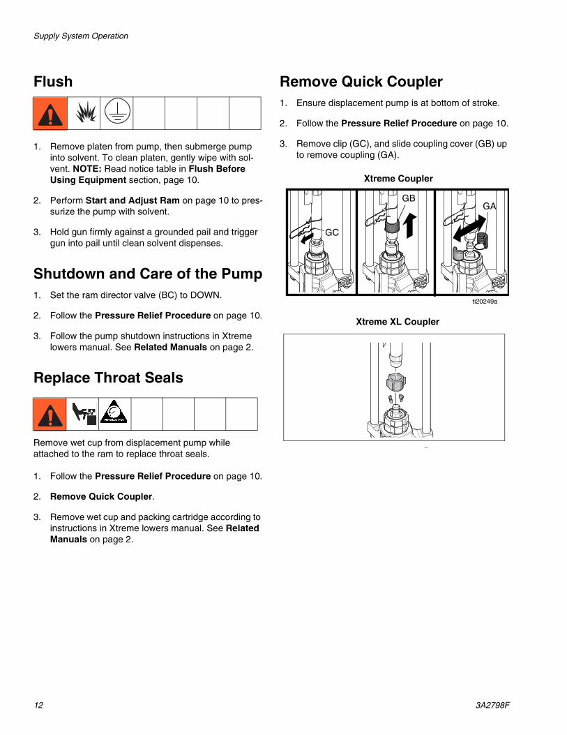
Remove Quick Coupler1. Ensure displacement pump is at bottom of stroke.
2. Follow the Pressure Relief Procedure on page 10.
3. Remove clip (GC), and slide coupling cover (GB) up to remove coupling (GA).
GB
GC
GA
ti20249a
Xtreme Coupler
Xtreme XL Coupler
Before Beginning Repair
3A2798F 13
Before Beginning Repair
Maintenance Procedures
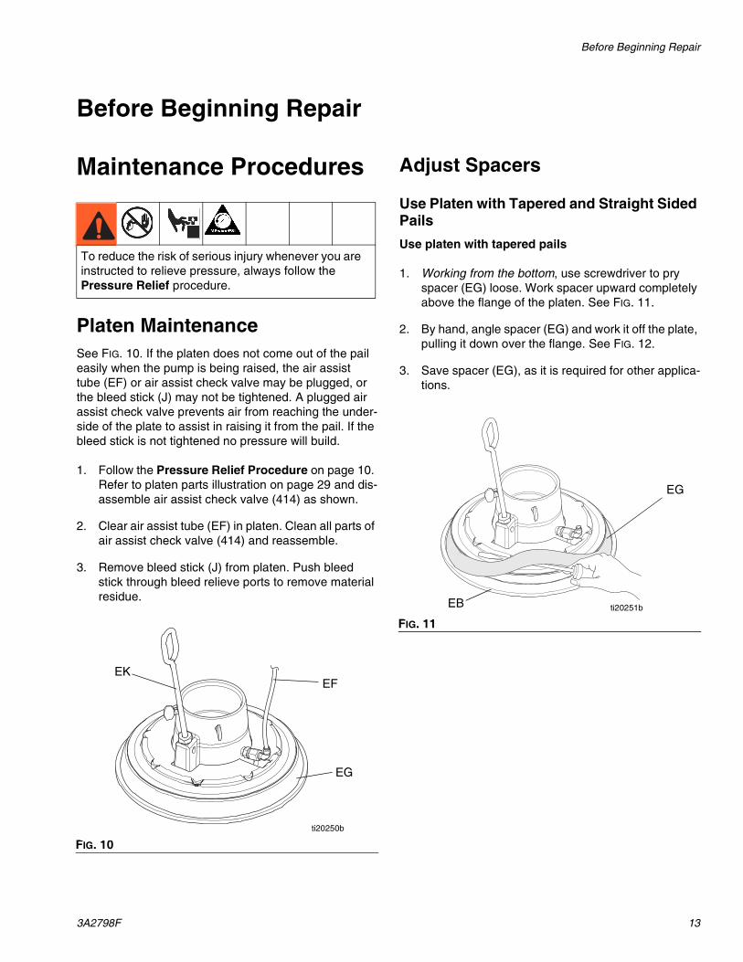
Platen MaintenanceSee FIG. 10. If the platen does not come out of the pail easily when the pump is being raised, the air assist tube (EF) or air assist check valve may be plugged, or the bleed stick (J) may not be tightened. A plugged air assist check valve prevents air from reaching the under-side of the plate to assist in raising it from the pail. If the bleed stick is not tightened no pressure will build.
1. Follow the Pressure Relief Procedure on page 10. Refer to platen parts illustration on page 29 and dis-assemble air assist check valve (414) as shown.
2. Clear air assist tube (EF) in platen. Clean all parts of air assist check valve (414) and reassemble.
3. Remove bleed stick (J) from platen. Push bleed stick through bleed relieve ports to remove material residue.
Adjust Spacers
Use Platen with Tapered and Straight Sided Pails
Use platen with tapered pails
1. Working from the bottom, use screwdriver to pry spacer (EG) loose. Work spacer upward completely above the flange of the platen. See FIG. 11.
2. By hand, angle spacer (EG) and work it off the plate, pulling it down over the flange. See FIG. 12.
3. Save spacer (EG), as it is required for other applica-tions.
To reduce the risk of serious injury whenever you are instructed to relieve pressure, always follow the Pressure Relief procedure.
FIG. 10
EG
EF
ti20250b
EK
FIG. 11
EG
EB ti20251b
Maintenance Procedures
14 3A2798F
Use platen with straight sided pail
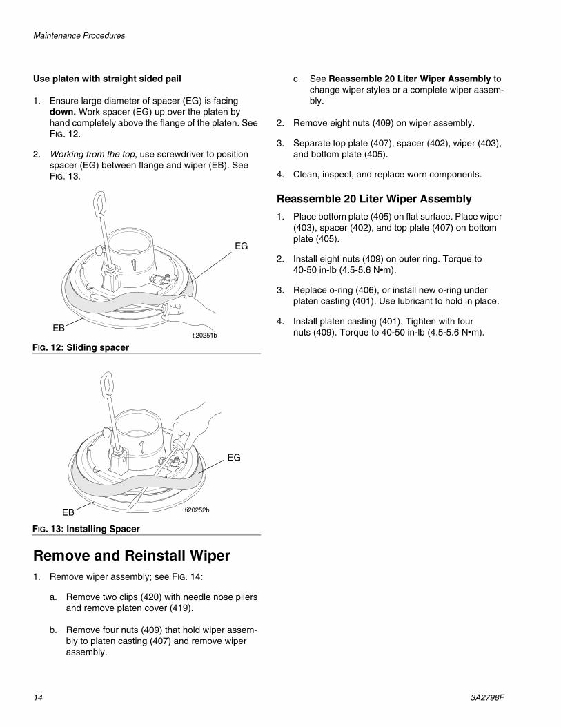
1. Ensure large diameter of spacer (EG) is facing down. Work spacer (EG) up over the platen by hand completely above the flange of the platen. See FIG. 12.
2. Working from the top, use screwdriver to position spacer (EG) between flange and wiper (EB). See FIG. 13.
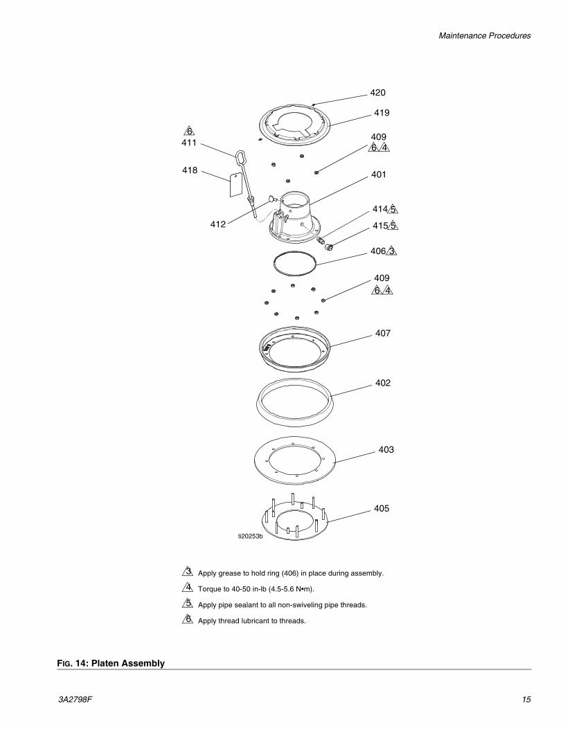
Remove and Reinstall Wiper1. Remove wiper assembly; see FIG. 14:
a. Remove two clips (420) with needle nose pliers and remove platen cover (419).
b. Remove four nuts (409) that hold wiper assem-bly to platen casting (407) and remove wiper assembly.
c. See Reassemble 20 Liter Wiper Assembly to change wiper styles or a complete wiper assem-bly.
2. Remove eight nuts (409) on wiper assembly.
3. Separate top plate (407), spacer (402), wiper (403), and bottom plate (405).
4. Clean, inspect, and replace worn components.
Reassemble 20 Liter Wiper Assembly
1. Place bottom plate (405) on flat surface. Place wiper (403), spacer (402), and top plate (407) on bottom plate (405).
2. Install eight nuts (409) on outer ring. Torque to 40-50 in-lb (4.5-5.6 N•m).
3. Replace o-ring (406), or install new o-ring under platen casting (401). Use lubricant to hold in place.
4. Install platen casting (401). Tighten with four nuts (409). Torque to 40-50 in-lb (4.5-5.6 N•m).
FIG. 12: Sliding spacer
FIG. 13: Installing Spacer
EG
EBti20251b
EG
EB ti20252b
Maintenance Procedures
3A2798F 15
FIG. 14: Platen Assembly
Apply grease to hold ring (406) in place during assembly.
Torque to 40-50 in-lb (4.5-5.6 N•m).
Apply pipe sealant to all non-swiveling pipe threads.
Apply thread lubricant to threads.
3
4
5
6
4116
418
414
415
409
409
401
412
419
420
406
407
402
403
405
3
6 4
6 4
ti20253b
5
5
Troubleshooting
16 3A2798F
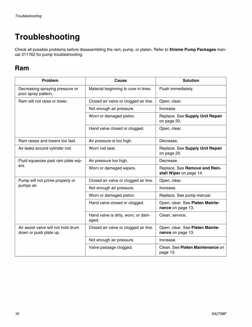
TroubleshootingCheck all possible problems before disassembling the ram, pump, or platen. Refer to Xtreme Pump Packages man-ual 311762 for pump troubleshooting.
Ram
Problem Cause Solution
Decreasing spraying pressure or poor spray pattern.
Material beginning to cure in lines. Flush immediately.
Ram will not raise or lower. Closed air valve or clogged air line. Open, clear.
Not enough air pressure. Increase.
Worn or damaged piston. Replace. See Supply Unit Repair on page 20.
Hand valve closed or clogged. Open, clear.
Ram raises and lowers too fast. Air pressure is too high. Decrease.
Air leaks around cylinder rod. Worn rod seal. Replace. See Supply Unit Repair on page 20.
Fluid squeezes past ram plate wip-ers.
Air pressure too high. Decrease.
Worn or damaged wipers. Replace. See Remove and Rein-stall Wiper on page 14.
Pump will not prime properly or pumps air.
Closed air valve or clogged air line. Open, clear.
Not enough air pressure. Increase.
Worn or damaged piston. Replace. See pump manual.
Hand valve closed or clogged. Open, clear. See Platen Mainte-nance on page 13.
Hand valve is dirty, worn, or dam-aged.
Clean, service.
Air assist valve will not hold drum down or push plate up.
Closed air valve or clogged air line. Open, clear. See Platen Mainte-nance on page 13.
Not enough air pressure. Increase.
Valve passage clogged. Clean. See Platen Maintenance on page 13.
Repair
3A2798F 17
Repair
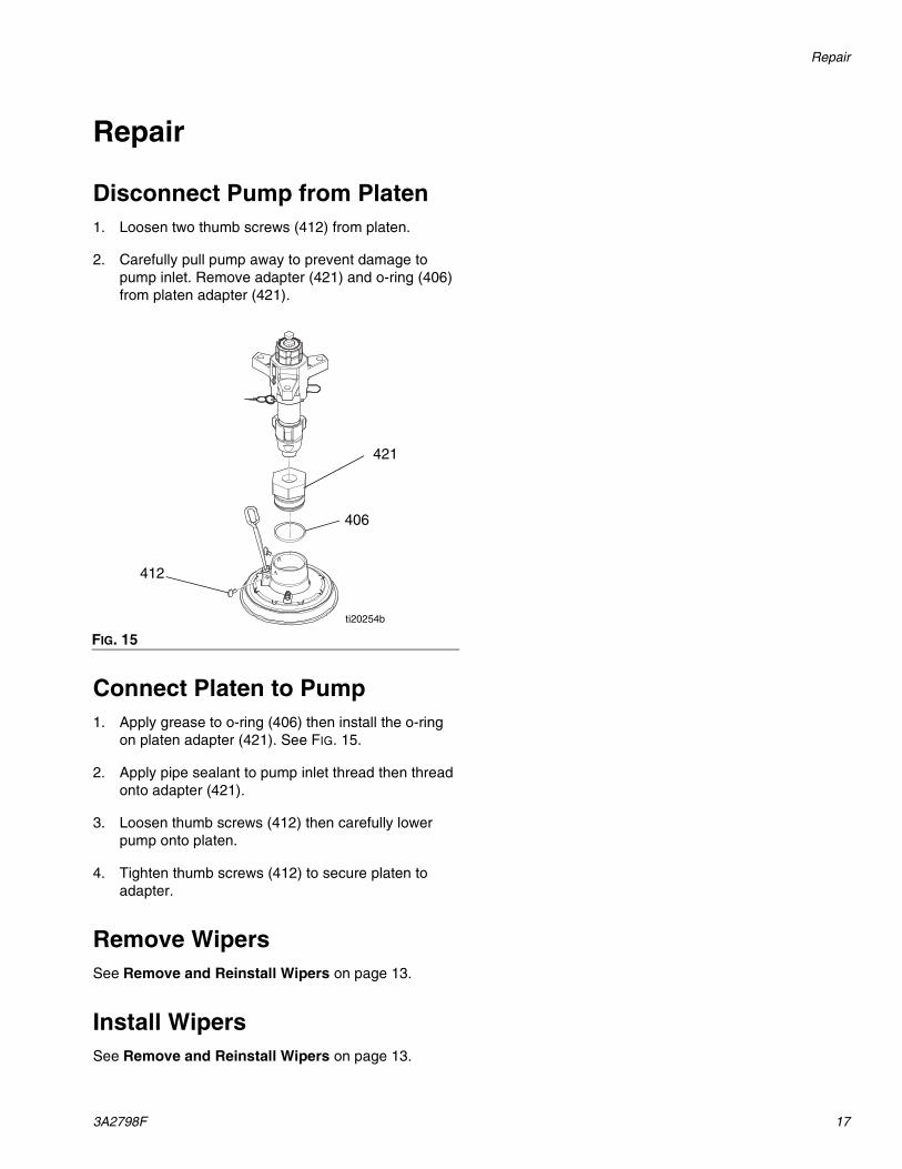
Disconnect Pump from Platen1. Loosen two thumb screws (412) from platen.
2. Carefully pull pump away to prevent damage to pump inlet. Remove adapter (421) and o-ring (406) from platen adapter (421).
Connect Platen to Pump1. Apply grease to o-ring (406) then install the o-ring
on platen adapter (421). See FIG. 15.
2. Apply pipe sealant to pump inlet thread then thread onto adapter (421).
3. Loosen thumb screws (412) then carefully lower pump onto platen.
4. Tighten thumb screws (412) to secure platen to adapter.
Remove WipersSee Remove and Reinstall Wipers on page 13.
Install WipersSee Remove and Reinstall Wipers on page 13.
FIG. 15
406
421
412
ti20254b
Repair
18 3A2798F
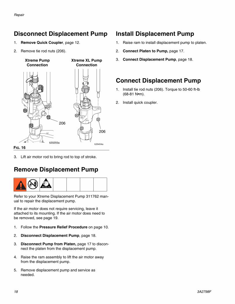
Disconnect Displacement Pump1. Remove Quick Coupler, page 12.
2. Remove tie rod nuts (206).
3. Lift air motor rod to bring rod to top of stroke.
Remove Displacement Pump
Refer to your Xtreme Displacement Pump 311762 man-ual to repair the displacement pump.
If the air motor does not require servicing, leave it attached to its mounting. If the air motor does need to be removed, see page 19.
1. Follow the Pressure Relief Procedure on page 10.
2. Disconnect Displacement Pump, page 18.
3. Disconnect Pump from Platen, page 17 to discon-nect the platen from the displacement pump.
4. Raise the ram assembly to lift the air motor away from the displacement pump.
5. Remove displacement pump and service as needed.
Install Displacement Pump1. Raise ram to install displacement pump to platen.
2. Connect Platen to Pump, page 17.
3. Connect Displacement Pump, page 18.
Connect Displacement Pump1. Install tie rod nuts (206). Torque to 50-60 ft-lb
(68-81 N•m).
2. Install quick coupler.
FIG. 16
206
ti20255a
Xtreme Pump Connection
Xtreme XL Pump Connection
206
Repair
3A2798F 19
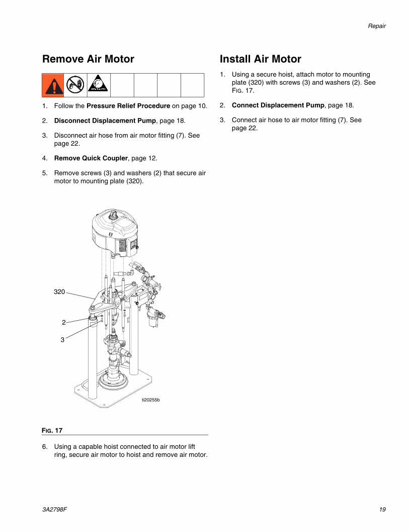
Remove Air Motor
1. Follow the Pressure Relief Procedure on page 10.
2. Disconnect Displacement Pump, page 18.
3. Disconnect air hose from air motor fitting (7). See page 22.
4. Remove Quick Coupler, page 12.
5. Remove screws (3) and washers (2) that secure air motor to mounting plate (320).
6. Using a capable hoist connected to air motor lift ring, secure air motor to hoist and remove air motor.
Install Air Motor1. Using a secure hoist, attach motor to mounting
plate (320) with screws (3) and washers (2). See FIG. 17.
2. Connect Displacement Pump, page 18.
3. Connect air hose to air motor fitting (7). See page 22.
FIG. 17
3
ti20255b
2
320
Repair
20 3A2798F
Supply Unit Repair
Ram Piston Rods
Always service both cylinders at the same time. When you service the piston rod always install new o-rings in the piston rod seal and ram piston.
Repair Parts:
Piston Repair Kit 257622. See Ram Frame on page 27 for parts included in kit.
Disassemble Piston Rod Seal and Bearing
1. Relieve pressure.
2. Access piston rod seal and bearing.
a. Ensure ram is in lowest position.
b. Remove nuts (333) and lockwashers (332) from piston rods (302a).
c. Remove entire pump package, including the mounting plate (331) off of the piston rods (302a). Use a fork-truck to lift the assembly from the mounting plate.
d. Secure pump package so pump and platen will not fall.
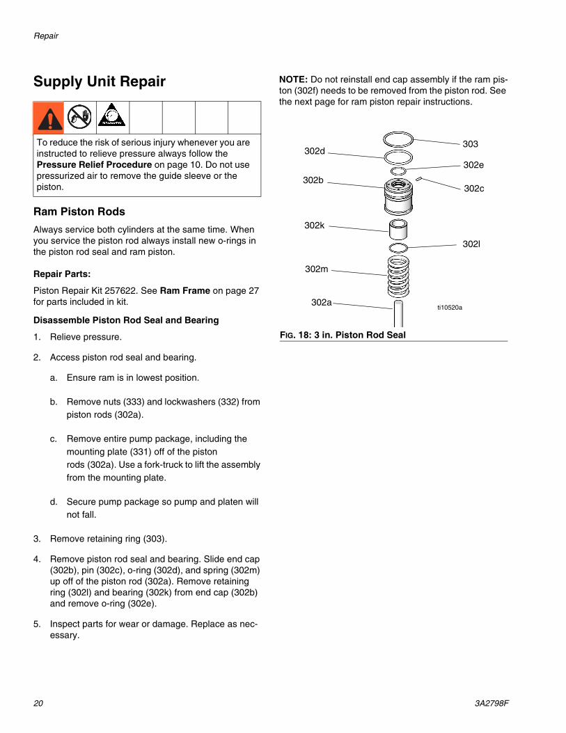
3. Remove retaining ring (303).
4. Remove piston rod seal and bearing. Slide end cap (302b), pin (302c), o-ring (302d), and spring (302m) up off of the piston rod (302a). Remove retaining ring (302l) and bearing (302k) from end cap (302b) and remove o-ring (302e).
5. Inspect parts for wear or damage. Replace as nec-essary.
NOTE: Do not reinstall end cap assembly if the ram pis-ton (302f) needs to be removed from the piston rod. See the next page for ram piston repair instructions.
To reduce the risk of serious injury whenever you are instructed to relieve pressure always follow the Pressure Relief Procedure on page 10. Do not use pressurized air to remove the guide sleeve or the piston.
FIG. 18: 3 in. Piston Rod Seal
ti10520a302a
302m
302l
302k
302b
302d303
302c
302e
Repair
3A2798F 21
Assemble Piston Rod Seal and Bearing
See FIG. 18 on page 20.
1. Lubricate o-ring (302e) and bottom bearing (302k).
a. Install o-ring (302e), bottom bearing (302j), and retaining ring (302l) into end cap (302b).
b. Install new o-ring (302d) and pin (302c) on end cap (302b). Lubricate o-ring (302d) and end cap (302b).
c. Slide spring (302m) and end cap (302b) on pis-ton rod (302a).
2. Install retaining ring (303).
3. Remount mounting plate (331) and attach nuts (333) and lockwashers (332). Torque to 40 ft-lb (54 N•m).
Disassemble Ram Piston
1. Complete steps 1-4 from Disassemble Piston Rod Seal and Bearing to remove the end cap (302b) from the piston rod (302a).
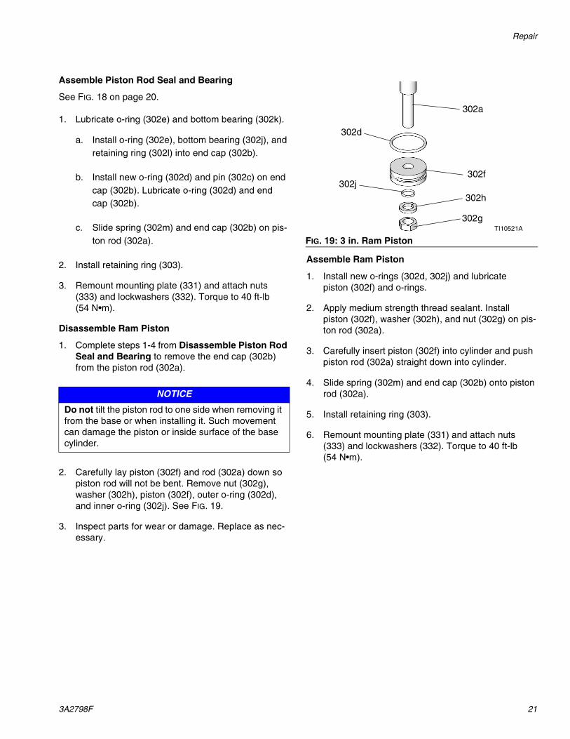
2. Carefully lay piston (302f) and rod (302a) down so piston rod will not be bent. Remove nut (302g), washer (302h), piston (302f), outer o-ring (302d), and inner o-ring (302j). See FIG. 19.
3. Inspect parts for wear or damage. Replace as nec-essary.
Assemble Ram Piston
1. Install new o-rings (302d, 302j) and lubricate piston (302f) and o-rings.
2. Apply medium strength thread sealant. Install piston (302f), washer (302h), and nut (302g) on pis-ton rod (302a).
3. Carefully insert piston (302f) into cylinder and push piston rod (302a) straight down into cylinder.
4. Slide spring (302m) and end cap (302b) onto piston rod (302a).
5. Install retaining ring (303).
6. Remount mounting plate (331) and attach nuts (333) and lockwashers (332). Torque to 40 ft-lb (54 N•m).
NOTICE
Do not tilt the piston rod to one side when removing it from the base or when installing it. Such movement can damage the piston or inside surface of the base cylinder.
FIG. 19: 3 in. Ram PistonTI10521A
302a
302d
302f302j
302h
302g
Parts
22 3A2798F
Parts
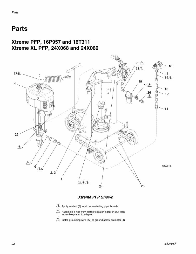
Xtreme PFP, 16P957 and 16T311Xtreme XL PFP, 24X068 and 24X069
4
221
2, 3
56
5
7
24
20
21
1819
255
Apply sealant (8) to all non-swiveling pipe threads.
Assemble o-ring from platen to platen adapter (22) then assemble platen to adapter.
Install grounding wire (27) to ground screw on motor (4).
1
5
8
27 8
11
12
13
1415
16
26
ti20231b
1
1
1
1
1
1
1
1
261
Xtreme PFP Shown
Parts
3A2798F 23
--- Not for sale.
❄ Not shown.
◆ Included in mix line and gun kit 24P832. See Con-nect Mix Line and Gun on page 9 for kit installation.
Ref Part Description Qty1 --- RAM, dual post, motor regulator 1
2 100133 WASHER, lock, 3/8 4
3 --- SCREW, cap, hex head 4
4 --- PUMP, Xtreme, PFP; 16T311 and 16P957 only
1
--- PUMP, Xtreme, XL; 24X068 and 24X069 only
1
5◆ 160032 FITTING, nipple 2
6◆ 16T481 VALVE, check 1
7 160327 FITTING, union adapter, 90 degree 1
8 --- SEALANT, pipe, stainless steel 1
10❄ 206994 FLUID, TSL, 8 oz bottle 1
11◆ H67550 HOSE, coupled, 3/4 in. ID, 6500 psi 1
12◆ 16R883 FITTING, nipple, reducing, 3/4 x 1/2 1
13◆ H75025 HOSE, coupled, 7250 psi, 0.50 in. ID, 25 ft
1
14◆ 158491 FITTING, nipple 1
15◆ 24P834 SWIVEL, straight 1
16◆ 262854 GUN, spray, XHF 1
18 113429 COUPLING, universal, 3/4-14 npt male
1
19 117628 FILTER, air, 3/4 (auto drain) 1
20 157785 FITTING, swivel 1
21 295847 FITTING, elbow, 90, 3/4 mpt 1
22 --- ADAPTER, platen 1
24 --- LABEL, identification 1
25 16P434 CART, ram (Model 16T311 only) 1
26 113430 COUPLING, universal, 3/4-14 npt female
1
27 238909 WIRE, grounding 1
Parts
24 3A2798F
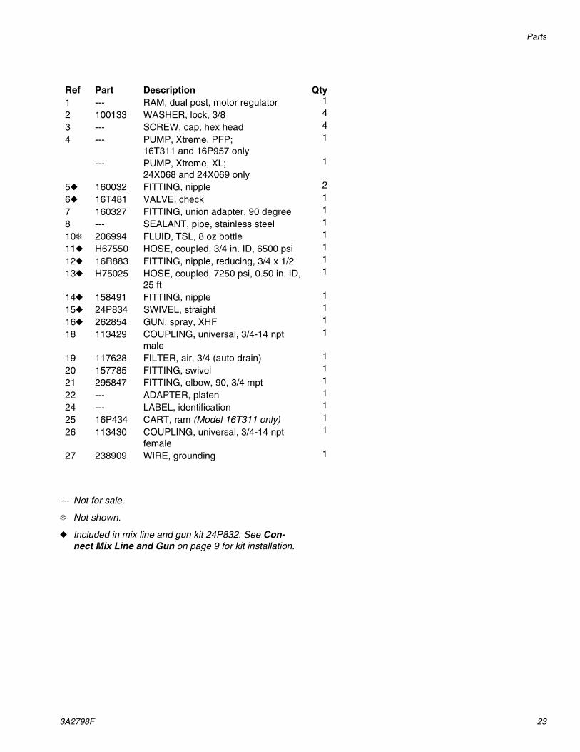
Cart, 16P434
--- Not for sale.
◆ Not shown.
ti20233a
120
110
109
101
108107
104103
104105
106
111112 113
102
104103
104105
106
3
Insert axle (8) into cart (101) then press pin (109) into axle (108).
Place handle (110) on top of axle (108) then press pin (109) into handle (110)
Apply grease to axles (102, 107, 108).
Apply anaerobic sealant to threads.
1
2
3
5
33
2
2
21
1091
121
521
Ref Part Description Qty101 --- CART 1102 --- AXLE 1103 113807 WHEEL, flat free, urethane 4104 191824 WASHER, space 8105 111841 WASHER, plain 5/8 4106 101242 RING, retaining, external 4107 15A913 AXLE 1108 --- AXLE 1109 124291 PIN, spring 2110 258982 HANDLE, cart 1111 --- BRAKE 2112 112788 SCREW, cap, socket head 8113 102962 SCREW, cap, socket head 2114 --- LUBRICANT, grease 1115◆ 101147 SCREW, cap, hex head 4116◆ 101044 WASHER, plain 8117◆ 100018 WASHER, lock, spring 4118◆ 100321 NUT 4119 --- SEALANT, anaerobic 1120 116139 GRIP, handle 2121 --- LABEL, arrow 2
Parts
3A2798F 25
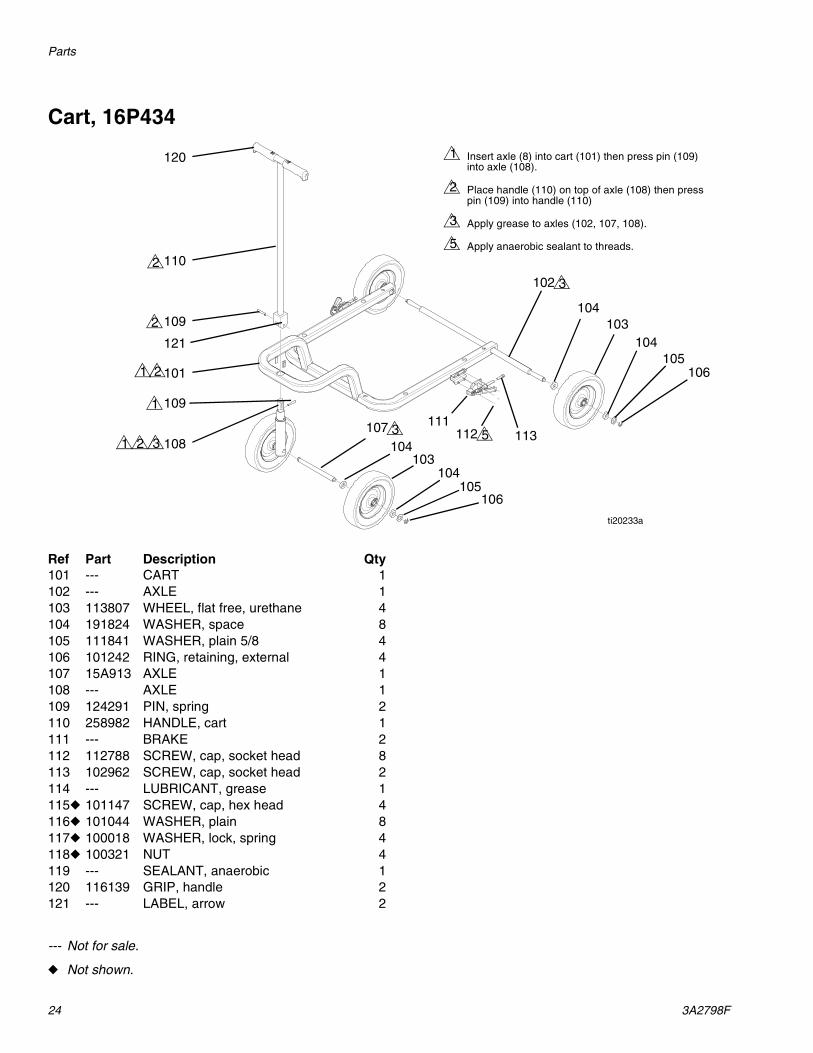
Xtreme Pumpline
--- Not for sale.
201,
7
Torque to 50-60 ft-lb (68-81 N•m).
Torque together to 145-155 ft-lb (196-210 N•m).
Apply sealant.
Insert lanyard from locking pin onto tie rod (2).
Apply thread lubricant to threads, o-rings, and seals. Do not apply to rod adapter (216) or rod (229).
Push in de-ice control (15) fully. Symbols must be upright.
1
2
3
4
5
7
215
202
229
216
203
204
207
206
205
1
2 3
2 34
1
212
ti20241a
Ref Part Description Qty201 N65DN0 MOTOR, 6500 1202 --- ROD, tie 3203 197340 COVER, coupler 1204 244819 COUPLING, assembly 1205 L180C7 LOWER, Xtreme 1206 101712 NUT, lock 3207 244820 CLIP, hairpin; with lanyard 1208 --- SEALANT, anaerobic 1212 --- LABEL, Xtreme PFP 1214 --- LUBRICANT, thread 1215 15J277 CONTROL, de-ice 1216 15H392 ADAPTER, rod, Xtreme 1229 --- ROD, adapter 1
Parts
26 3A2798F
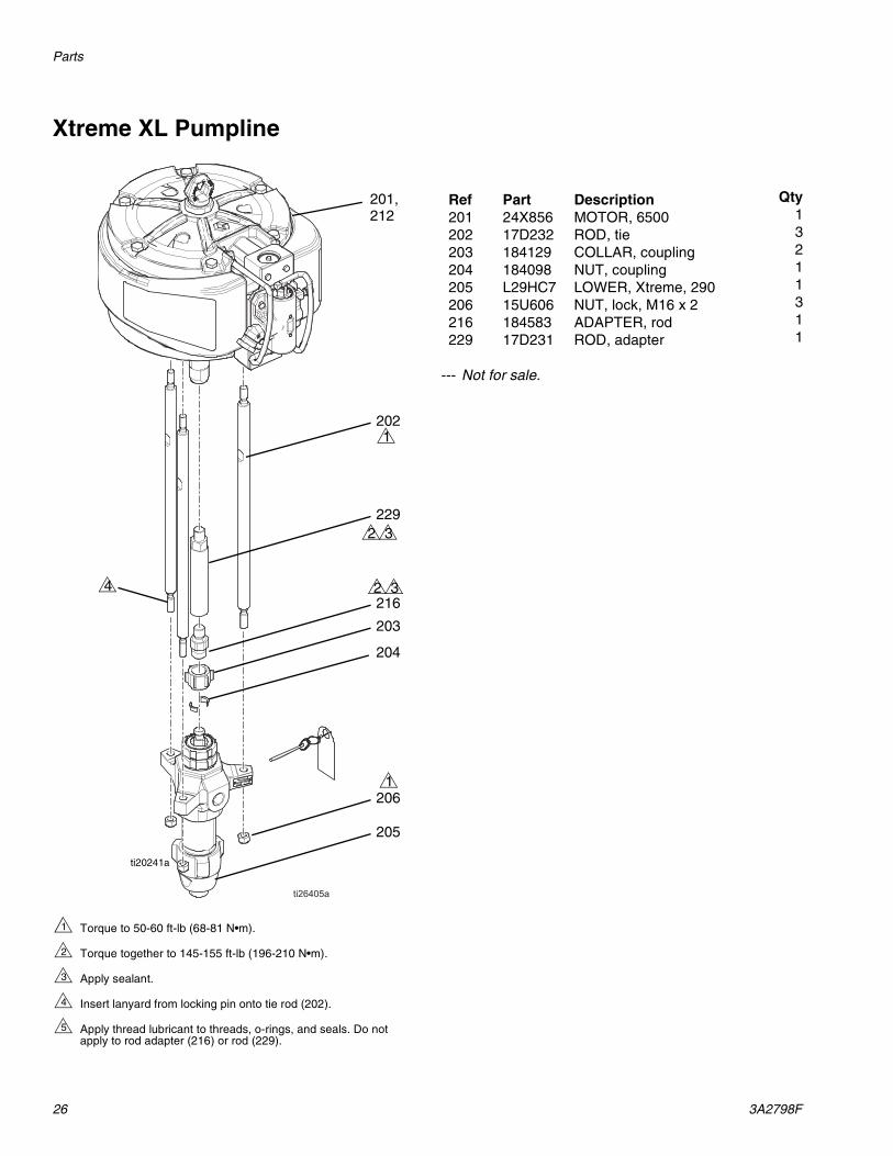
Xtreme XL Pumpline
--- Not for sale.
201,
Torque to 50-60 ft-lb (68-81 N•m).
Torque together to 145-155 ft-lb (196-210 N•m).
Apply sealant.
Insert lanyard from locking pin onto tie rod (202).
Apply thread lubricant to threads, o-rings, and seals. Do not apply to rod adapter (216) or rod (229).
1
2
3
4
5
202
229
216
203
204
206
205
1
2 3
2 34
1
212
ti20241a
Ref Part Description Qty201 24X856 MOTOR, 6500 1202 17D232 ROD, tie 3203 184129 COLLAR, coupling 2204 184098 NUT, coupling 1205 L29HC7 LOWER, Xtreme, 290 1206 15U606 NUT, lock, M16 x 2 3216 184583 ADAPTER, rod 1229 17D231 ROD, adapter 1
Parts
3A2798F 27
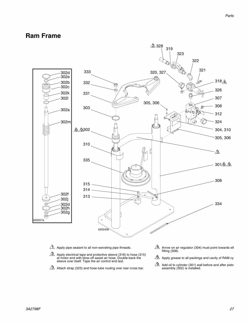
Ram Frame
Apply pipe sealant to all non-swiveling pipe threads.
Apply electrical tape and protective sleeve (316) to hose (315) at motor end with blow-off assist air hose. Double-back the sleeve over itself. Tape the air control end last.
Attach strap (323) and hose-tube routing over rear cross bar.
Arrow on air regulator (304) must point towards elbfitting (308).
Apply grease to all packings and cavity of RAM cy
Add oil to cylinder (301) wall before and after pistoassembly (302) is installed.
1
2
3
4
6
9
2
333
332
331
321320, 327
301
324
326
322
323319
328
334
4
3
ti20240b
302
310
303
335
318
312
308
305, 306
304, 310
315314
313
305, 306307
308
6 9
96
302d302e
302c302b
302k302l
302a
302m
302f302j302d302h302g
ti20257a
Parts
28 3A2798F
Ram Frame Parts
--- Not for sale.
▲ Replacement Danger and Warning labels, tags and cards are available at no cost.
◆ Included in kit 257622.
Ref Part Description Qty
301 --- RAM, dp, weldment 1
302◆ --- PISTON, ram, subassembly (includes items 302a-302p)
2
302a◆ --- ROD, piston, ram 1
302b◆ 15M295 BEARING, ram end cap 1
302c◆ 15U979 PIN, spring, straight 1
302d◆ 160258 PACKING, o-ring, buna-n 2
302e◆ 156698 PACKING, o-ring 1
302f◆ 183943 PISTON 1
302g◆ 101535 NUT, full hex 1
302h◆ 101533 WASHER, spring lock 1
302j◆ 156401 PACKING, o-ring 1
302k◆ --- BEARING, ram end cap 1
302l◆ 15F453 RETAINER, retaining ring 1
302m◆ 160138 SPRING, compression 1
302n◆ --- LUBRICANT, grease 1
302p◆ --- SEALANT, thread, medium strength
1
303◆ --- RING, retaining 2
304 255296 BRACKET, mounted 1
305 100016 WASHER, lock 8
306 101682 SCREW, socket cap head 8
307 24C824 CONTROL, air, ram, hydraulic driver
1
308 597151 FITTING, elbow 2
309 --- LUBRICANT, grease 1
310▲ 15J074 LABEL, safety, crush and pinch 4
311 --- SEALANT, pipe, sst 1
312 --- LABEL, valve, shutoff, air con-trol
1
313 C32467 STOP, drum 2
314 C38185 WASHER, lock 2
315 C19853 SCREW, cap, socket head 2
316 C12509 TUBE, nylon, round 14
317 --- LUBRICANT, oil 1
318 16F014 REGULATOR, air, t-handle 1
319 157785 FITTING, swivel 1
320 100960 GAUGE, pressure, air 1
321 103347 VALVE, safety, 100 psi; Xtreme only
1
113498 VALVE, safety, 110 psi; Xtreme XL only
1
322 --- FITTING, elbow, street, 3/4-14 1
323 113218 VALVE, ball, vented, 0.750 1
324 101689 GAUGE, press, air 1
326 C20487 FITTING, nipple, hex 1
327 100840 FITTING, elbow, street 1
328 C12034 HOSE, coupled 72 in. 1
329 552071 SLEEVE, protective 15
330 --- TAPE, electrical 1
331 --- BRACKET, shelf, D60, 3400 / 6500
1
332 101533 WASHER, spring lock 2
333 101535 NUT, full hex 2
334 198442 STRAP, retaining mix manifold 1
335 16U676 PLATE, 20 L single wiper; see manual 3A3113
1
Ref Part Description Qty
Parts
3A2798F 29
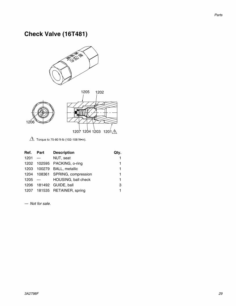
Check Valve (16T481)
--- Not for sale.
Ref. Part Description Qty.1201 --- NUT, seat 11202 102595 PACKING, o-ring 11203 100279 BALL, metallic 11204 108361 SPRING, compression 11205 --- HOUSING, ball check 11206 181492 GUIDE, ball 31207 181535 RETAINER, spring 1
1205
12011207 1204 1203
1202
1206
1
Torque to 75-80 ft-lb (102-108 N•m).1
Accessories
30 3A2798F
Accessories
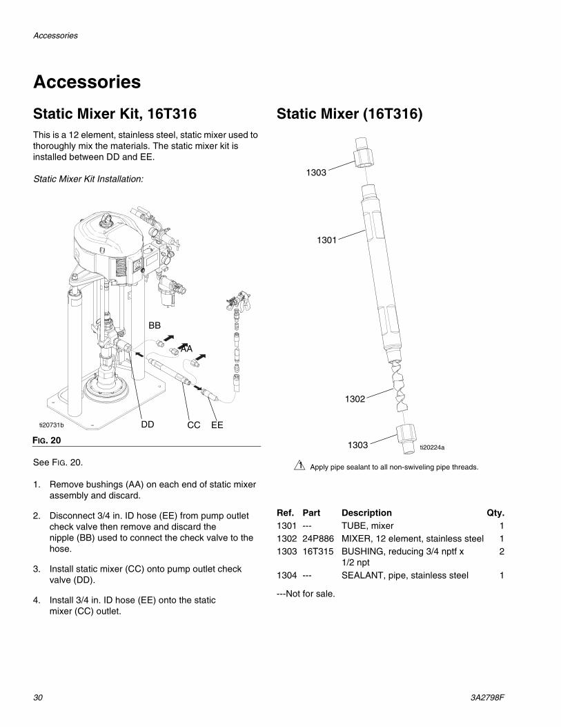
Static Mixer Kit, 16T316This is a 12 element, stainless steel, static mixer used to thoroughly mix the materials. The static mixer kit is installed between DD and EE.
Static Mixer Kit Installation:
See FIG. 20.
1. Remove bushings (AA) on each end of static mixer assembly and discard.
2. Disconnect 3/4 in. ID hose (EE) from pump outlet check valve then remove and discard the nipple (BB) used to connect the check valve to the hose.
3. Install static mixer (CC) onto pump outlet check valve (DD).
4. Install 3/4 in. ID hose (EE) onto the static mixer (CC) outlet.
Static Mixer (16T316)
---Not for sale.
FIG. 20
ti20731b
BB
AA
CCDD EE
Ref. Part Description Qty.1301 --- TUBE, mixer 11302 24P886 MIXER, 12 element, stainless steel 11303 16T315 BUSHING, reducing 3/4 nptf x
1/2 npt2
1304 --- SEALANT, pipe, stainless steel 1
1303
1301
1302
1303 ti20224a
Apply pipe sealant to all non-swiveling pipe threads.1
Dimensions
3A2798F 31
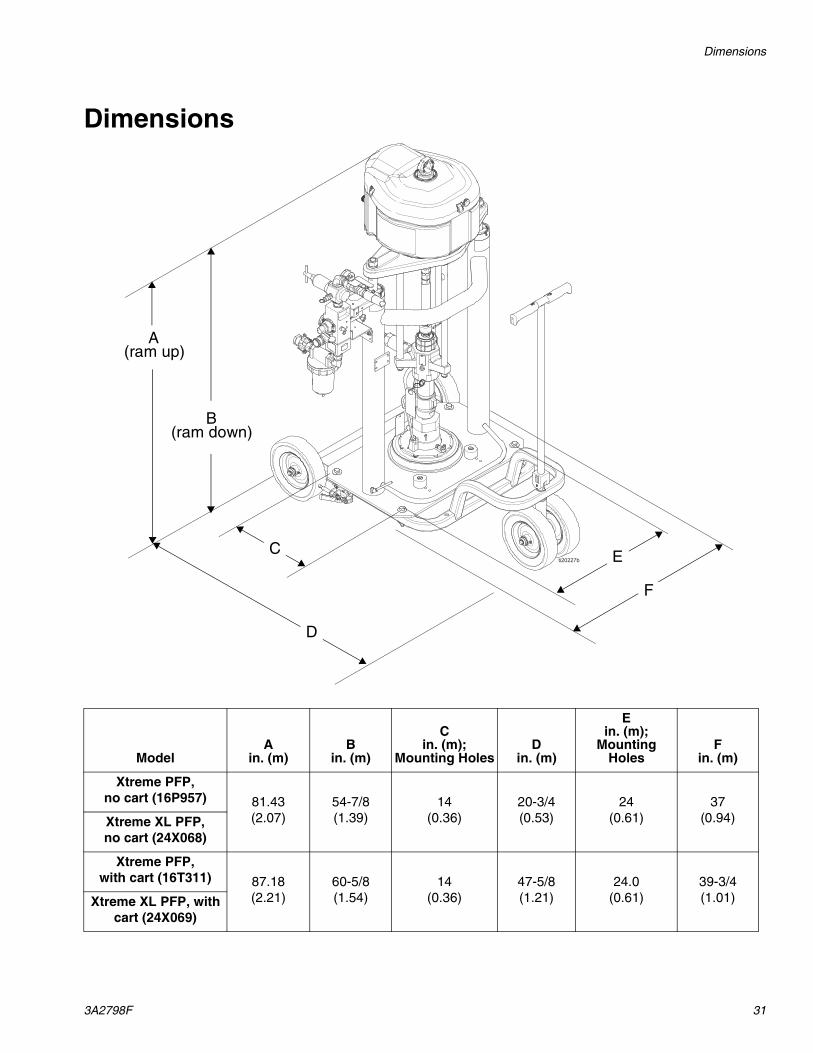
Dimensions
(ram up)A
(ram down)B
F
E
D
C
ModelA
in. (m)B
in. (m)
Cin. (m);
Mounting HolesD
in. (m)
Ein. (m);
Mounting Holes
Fin. (m)
Xtreme PFP, no cart (16P957) 81.43
(2.07)54-7/8(1.39)
14(0.36)
20-3/4(0.53)
24(0.61)
37(0.94)Xtreme XL PFP,
no cart (24X068)
Xtreme PFP,with cart (16T311) 87.18
(2.21)60-5/8(1.54)
14(0.36)
47-5/8(1.21)
24.0(0.61)
39-3/4(1.01)Xtreme XL PFP, with
cart (24X069)
Technical Data
32 3A2798F
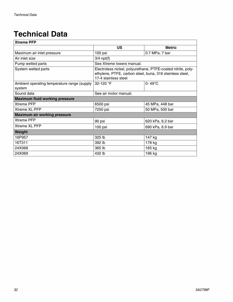
Technical DataXtreme PFP
US MetricMaximum air inlet pressure 100 psi 0.7 MPa, 7 barAir inlet size 3/4 npt(f)Pump wetted parts See Xtreme lowers manual.System wetted parts Electroless nickel, polyurethane, PTFE-coated nitrile, poly-
ethylene, PTFE, carbon steel, buna, 316 stainless steel, 17-4 stainless steel
Ambient operating temperature range (supply system
32-120 °F 0- 49°C
Sound data See air motor manual.Maximum fluid working pressureXtreme PFP 6500 psi 45 MPa, 448 barXtreme XL PFP 7250 psi 50 MPa, 500 barMaximum air working pressureXtreme PFP 90 psi 620 kPa, 6.2 barXtreme XL PFP 100 psi 690 kPa, 6.9 barWeight16P957 325 lb 147 kg16T311 392 lb 178 kg24X068 365 lb 165 kg24X069 432 lb 196 kg
Technical Data
3A2798F 33
All written and visual data contained in this document reflects the latest product information available at the time of publication. Graco reserves the right to make changes at any time without notice.
For patent information, see www.graco.com/patents.
Original instructions. This manual contains English. MM 3A2798
Graco Headquarters: MinneapolisInternational Offices: Belgium, China, Japan, Korea
GRACO INC. AND SUBSIDIARIES • P.O. BOX 1441 • MINNEAPOLIS MN 55440-1441 • USA
Copyright 2012, Graco Inc. All Graco manufacturing locations are registered to ISO 9001.www.graco.com
Revision F, June 2015
Graco Standard WarrantyGraco warrants all equipment referenced in this document which is manufactured by Graco and bearing its name to be free from defects in material and workmanship on the date of sale to the original purchaser for use. With the exception of any special, extended, or limited warranty published by Graco, Graco will, for a period of twelve months from the date of sale, repair or replace any part of the equipment determined by Graco to be defective. This warranty applies only when the equipment is installed, operated and maintained in accordance with Graco’s written recommendations.
This warranty does not cover, and Graco shall not be liable for general wear and tear, or any malfunction, damage or wear caused by faulty installation, misapplication, abrasion, corrosion, inadequate or improper maintenance, negligence, accident, tampering, or substitution of non-Graco component parts. Nor shall Graco be liable for malfunction, damage or wear caused by the incompatibility of Graco equipment with structures, accessories, equipment or materials not supplied by Graco, or the improper design, manufacture, installation, operation or maintenance of structures, accessories, equipment or materials not supplied by Graco.
This warranty is conditioned upon the prepaid return of the equipment claimed to be defective to an authorized Graco distributor for verification of the claimed defect. If the claimed defect is verified, Graco will repair or replace free of charge any defective parts. The equipment will be returned to the original purchaser transportation prepaid. If inspection of the equipment does not disclose any defect in material or workmanship, repairs will be made at a reasonable charge, which charges may include the costs of parts, labor, and transportation.
THIS WARRANTY IS EXCLUSIVE, AND IS IN LIEU OF ANY OTHER WARRANTIES, EXPRESS OR IMPLIED, INCLUDING BUT NOT LIMITED TO WARRANTY OF MERCHANTABILITY OR WARRANTY OF FITNESS FOR A PARTICULAR PURPOSE.
Graco’s sole obligation and buyer’s sole remedy for any breach of warranty shall be as set forth above. The buyer agrees that no other remedy (including, but not limited to, incidental or consequential damages for lost profits, lost sales, injury to person or property, or any other incidental or consequential loss) shall be available. Any action for breach of warranty must be brought within two (2) years of the date of sale.
GRACO MAKES NO WARRANTY, AND DISCLAIMS ALL IMPLIED WARRANTIES OF MERCHANTABILITY AND FITNESS FOR A PARTICULAR PURPOSE, IN CONNECTION WITH ACCESSORIES, EQUIPMENT, MATERIALS OR COMPONENTS SOLD BUT NOT MANUFACTURED BY GRACO. These items sold, but not manufactured by Graco (such as electric motors, switches, hose, etc.), are subject to the warranty, if any, of their manufacturer. Graco will provide purchaser with reasonable assistance in making any claim for breach of these warranties.
In no event will Graco be liable for indirect, incidental, special or consequential damages resulting from Graco supplying equipment hereunder, or the furnishing, performance, or use of any products or other goods sold hereto, whether due to a breach of contract, breach of warranty, the negligence of Graco, or otherwise.
FOR GRACO CANADA CUSTOMERSThe Parties acknowledge that they have required that the present document, as well as all documents, notices and legal proceedings entered into, given or instituted pursuant hereto or relating directly or indirectly hereto, be drawn up in English. Les parties reconnaissent avoir convenu que la rédaction du présente document sera en Anglais, ainsi que tous documents, avis et procédures judiciaires exécutés, donnés ou intentés, à la suite de ou en rapport, directement ou indirectement, avec les procédures concernées.
Graco InformationFor the latest information about Graco products, visit www.graco.com.
TO PLACE AN ORDER, contact your Graco distributor or call to identify the nearest distributor.Phone: 612-623-6921 or Toll Free: 1-800-328-0211 Fax: 612-378-3505