Embed Size (px)
Citation preview
1
1
2
2
3
3
4
4
5
5
6
6
A A
B B
C C
D D
Designed by Drawn by Approved by - date Date
Edition Sheet
/
Earth
Earth - Mobile Unit 01Visual Works
Tony Donnelly Nick Taylor 08/06/2005
4 1 4
A3
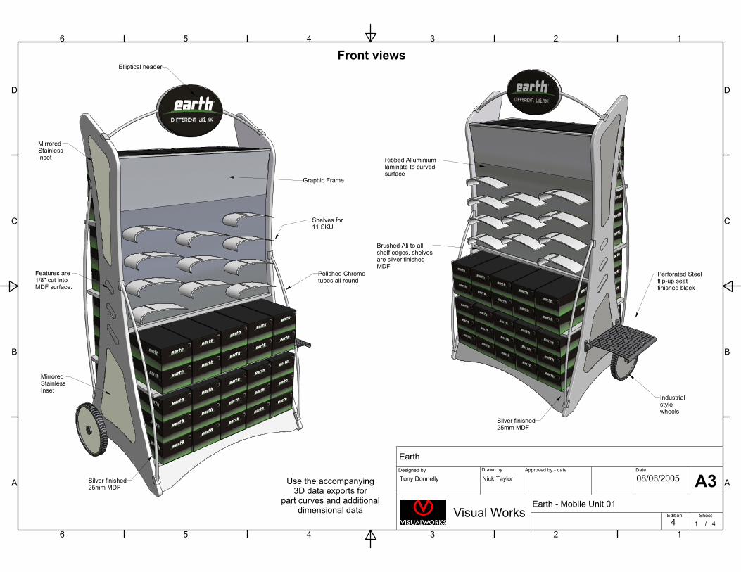
Front viewsElliptical header
Silver finished25mm MDF
MirroredStainlessInset
Features are1/8" cut intoMDF surface.
MirroredStainlessInset
Graphic Frame
Shelves for11 SKU
Ribbed Alluminiumlaminate to curvedsurface
Polished Chrometubes all round
Industrialstylewheels
Silver finished25mm MDF
Brushed Ali to allshelf edges, shelvesare silver finishedMDF
Use the accompanying3D data exports for
part curves and additionaldimensional data
Perforated Steelflip-up seatfinished black
1
1
2
2
3
3
4
4
5
5
6
6
A A
B B
C C
D D
Designed by Drawn by Approved by - date Date
Edition Sheet
/
Earth
Earth - Mobile Unit 01Visual Works
Tony Donnelly Nick Taylor 08/06/2005
4 2 4
A3
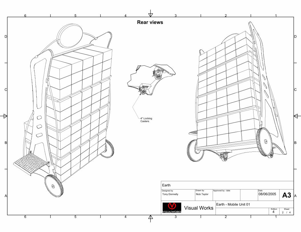
Rear views
4" LockingCasters
Front Front SideSide BackBack1
1
2
2
3
3
4
4
5
5
6
6
A A
B B
C C
D D
Designed by Drawn by Approved by - date Date
Edition Sheet
/
Earth
Earth - Mobile Unit 01Visual Works
Tony Donnelly Nick Taylor 08/06/2005
4 3 4
A3
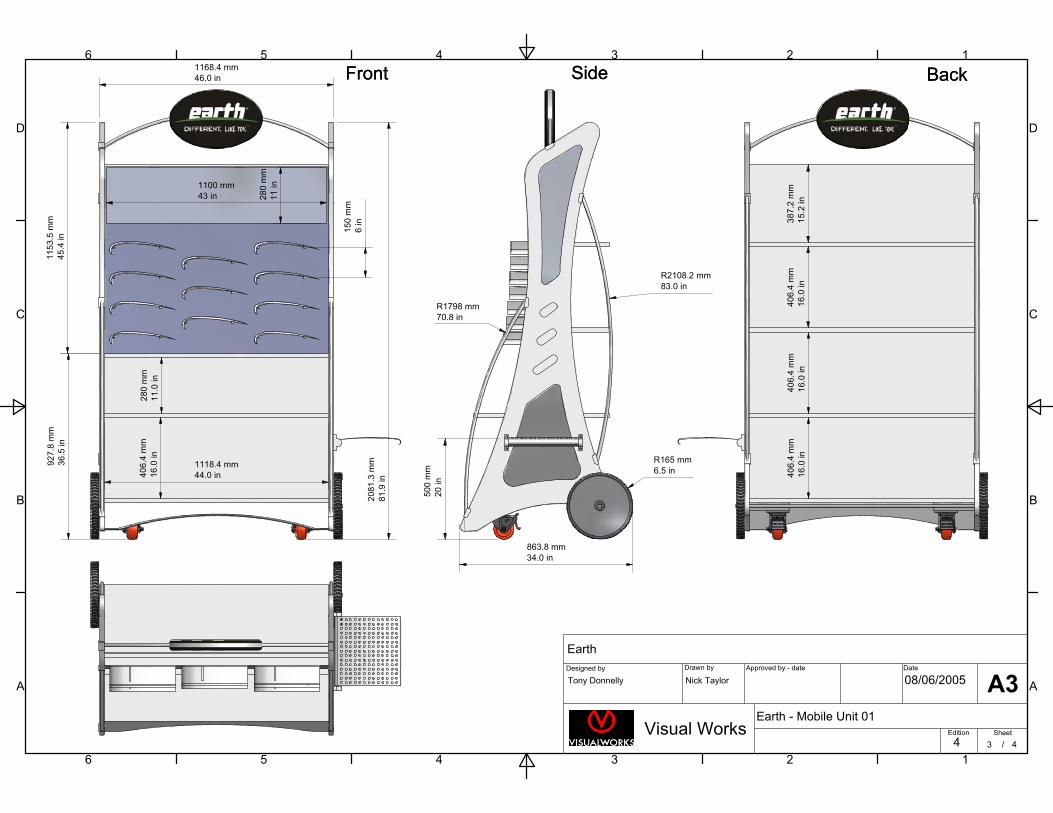
2081
.3m
m81
.9in
1168.4 mm46.0 in
927.
8m
m36
.5in
1153
.5m
m45
.4in
863.8 mm34.0 in
406.
4m
m16
.0in
280
mm
11.0
in
1118.4 mm44.0 in 40
6.4
mm
16.0
in40
6.4
mm
16.0
in40
6.4
mm
16.0
in38
7.2
mm
15.2
in
R2108.2 mm83.0 in
R1798 mm70.8 in
R165 mm6.5 in
500
mm
20in
150
mm
6in
1100 mm43 in 28
0m
m11
in
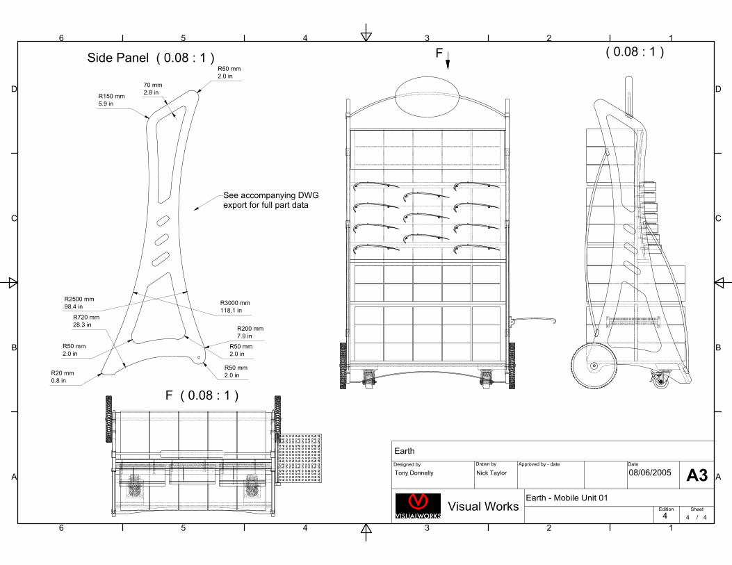
Side Panel ( 0.08 : 1 ) ( 0.08 : 1 )
F ( 0.08 : 1 )
1
1
2
2
3
3
4
4
5
5
6
6
A A
B B
C C
D D
Designed by Drawn by Approved by - date Date
Edition Sheet
/
Earth
Earth - Mobile Unit 01Visual Works
Tony Donnelly Nick Taylor 08/06/2005
4 4 4
A3
F
R2500 mm98.4 in R3000 mm
118.1 inR720 mm28.3 in
R50 mm2.0 in
R50 mm2.0 in
R200 mm7.9 in
R50 mm2.0 inR20 mm
0.8 in
R150 mm5.9 in
R50 mm2.0 in
70 mm2.8 in
See accompanying DWGexport for full part data
1
1
2
2
3
3
4
4
5
5
6
6
A A
B B
C C
D D
Designed by Drawn by Approved by - date Date
Edition Sheet
/
J Stephens Store Concept
JS - Cash Desk 01Visual Works
Tony Donnelly Nick Taylor 30/04/2005
1 1 3
A3
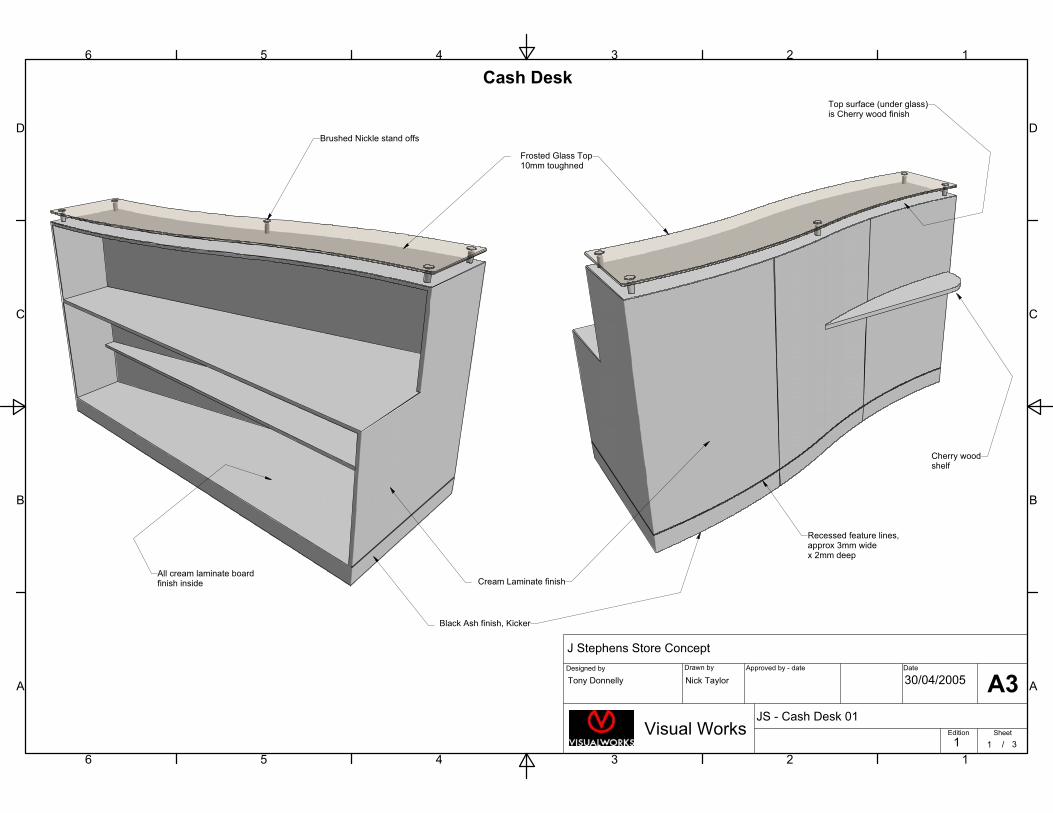
Frosted Glass Top10mm toughned
Brushed Nickle stand offs
Cherry woodshelf
Cream Laminate finish
Black Ash finish, Kicker
All cream laminate boardfinish inside
Top surface (under glass)is Cherry wood finish
Cash Desk
Recessed feature lines,approx 3mm wide x 2mm deep
1
1
2
2
3
3
4
4
5
5
6
6
A A
B B
C C
D D
Designed by Drawn by Approved by - date Date
Edition Sheet
/
J Stephens Store Concept
JS - Cash Desk 01Visual Works
Tony Donnelly Nick Taylor 30/04/2005
1 2 3
A3
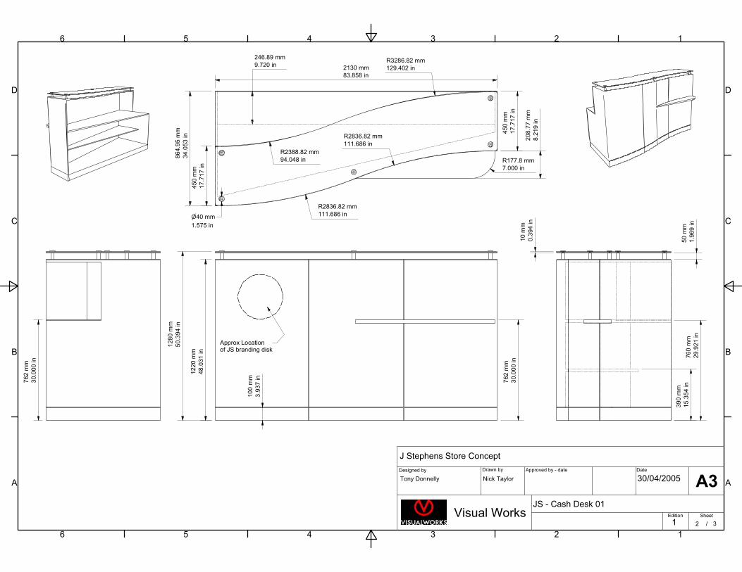
86
4.9
5m
m
34
.05
3in
2130 mm
83.858 in
45
0m
m
17
.717
in
20
8.7
7m
m
8.2
19
in
R177.8 mm
7.000 in1
28
0m
m
50.3
94
in
12
20
mm
48
.03
1in
762
mm
30.0
00
in
R2836.82 mm
111.686 in
R2388.82 mm
94.048 in
R2836.82 mm
111.686 in
R3286.82 mm
129.402 in
45
0m
m
17
.71
7in
100
mm
3.9
37
in
Approx Locationof JS branding disk
760
mm
29.9
21
in
39
0m
m
15
.35
4in
50
mm
1.9
69
in
10
mm
0.3
94
in
762
mm
30.0
00
in
40 mm
1.575 in
246.89 mm
9.720 in
( 1 : 10 )
1
1
2
2
3
3
4
4
5
5
6
6
A A
B B
C C
D D
Designed by Drawn by Approved by - date Date
Edition Sheet
/
J Stephens Store Concept
JS - Cash Desk 01Visual Works
Tony Donnelly Nick Taylor 30/04/2005
1 3 3
A3
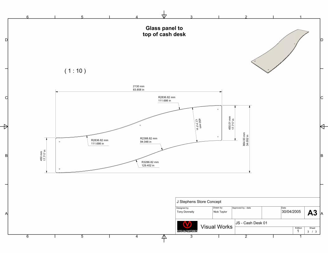
450
mm
17.7
17
in
45
0.0
1m
m
17
.71
7in
86
4.9
3m
m
34
.052
in
R2836.82 mm
111.686 in
R3286.82 mm
129.402 in
R2388.82 mm
94.048 in
R2836.82 mm
111.686 in
45
0m
m
17.7
17
in
2130 mm
83.858 in
Glass panel totop of cash desk
1
1
2
2
3
3
4
4
5
5
6
6
A A
B B
C C
D D
Designed by Drawn by Approved by - date Date
Edition Sheet
/
J Stephens Store Concept
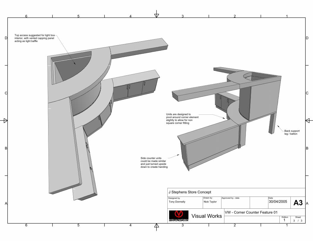
VW - Corner Counter Feature 01Visual Works
Tony Donnelly Nick Taylor 30/04/2005
1 1 3
A3
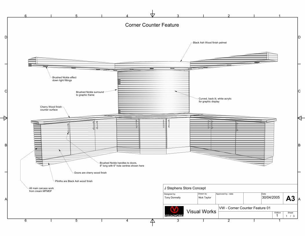
Black Ash Wood finish pelmet
Brushed Nickle surroundto graphic frame
Curved, back lit, white acrylicfor graphic display
Brushed Nickle effectdown light fittings
All main carcass workfrom cream MFMDF
Doors are cherry wood finish
Plinths are Black Ash wood finish
Brushed Nickle handles to doors,8" long with 6" hole centres shown here
Cherry Wood finishcounter surface
Corner Counter Feature
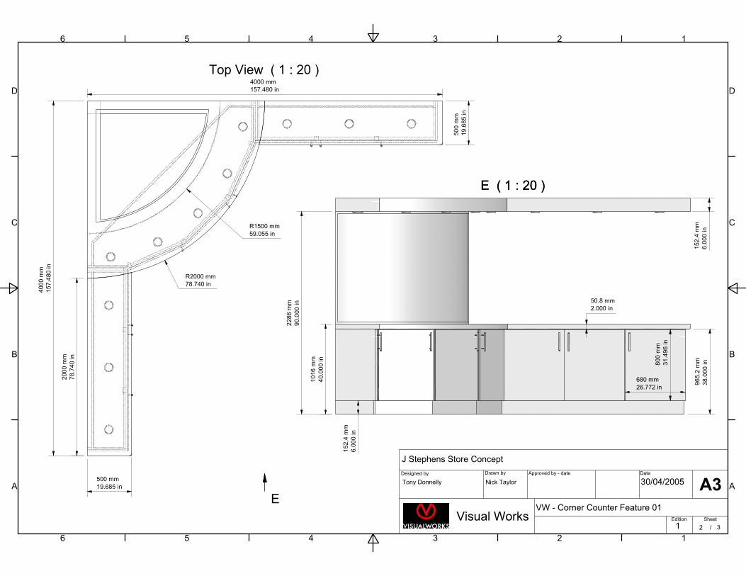
Top View ( 1 : 20 )
E ( 1 : 20 )E ( 1 : 20 )
1
1
2
2
3
3
4
4
5
5
6
6
A A
B B
C C
D D
Designed by Drawn by Approved by - date Date
Edition Sheet
/
J Stephens Store Concept
VW - Corner Counter Feature 01Visual Works
Tony Donnelly Nick Taylor 30/04/2005
1 2 3
A3E
4000 mm
157.480 in
400
0m
m
157
.48
0in
200
0m
m
78.7
40
in
R2000 mm
78.740 in
R1500 mm
59.055 in
15
2.4
mm
6.0
00
in
1016
mm
40.0
00
in
22
86
mm
90
.000
in
96
5.2
mm
38
.000
in80
0m
m
31
.49
6in
680 mm
26.772 in
500
mm
19.6
85
in
500 mm
19.685 in
50.8 mm
2.000 in
152
.4m
m
6.0
00
in
1
1
2
2
3
3
4
4
5
5
6
6
A A
B B
C C
D D
Designed by Drawn by Approved by - date Date
Edition Sheet
/
J Stephens Store Concept
VW - Corner Counter Feature 01Visual Works
Tony Donnelly Nick Taylor 30/04/2005
1 3 3
A3
Top access suggested for light boxinterior, with vented capping panelacting as light baffle
Units are designed topivot around corner elementslightly to allow for nonsquare corner fitting
Back supportleg / batton
Side counter unitscould be made similarand just turned upsidedown to create handing
1
1
2
2
3
3
4
4
5
5
6
6
A A
B B
C C
D D
Designed by Drawn by Approved by - date Date
Edition Sheet
/
J Stephens Store Concept
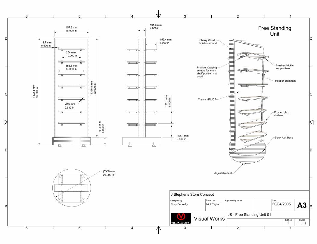
JS - Free Standing Unit 01
Visual Works
Tony Donnelly Nick Taylor 30/04/2005
1 1 1
A3
Cherry Woodfinish surround
Brushed Nicklesupport bars
Rubber grommets
Frosted plexishelves
Cream MFMDF
Black Ash Base
Adjustable feet
14
22.4
mm
56
.00
0in
101
.6m
m
4.0
00
in
13
20.8
mm
52
.00
0in
457.2 mm
18.000 in
101.6 mm
4.000 in
254 mm
10.000 in
355.6 mm
14.000 in
165
.1m
m
6.5
00
in
152.4 mm
6.000 in
508 mm
20.000 in
12.7 mm
0.500 in
Free StandingUnit
165.1 mm
6.500 in
Provide 'Capping'screws for whenshelf position notused
16 mm
0.630 in
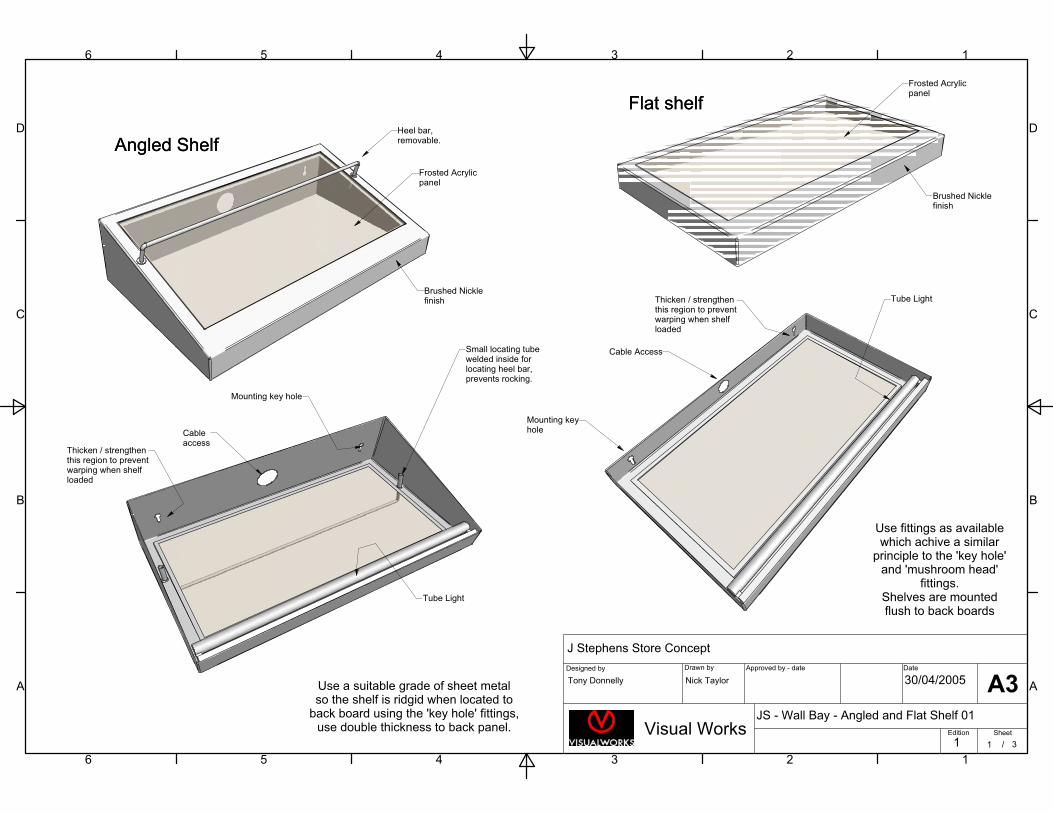
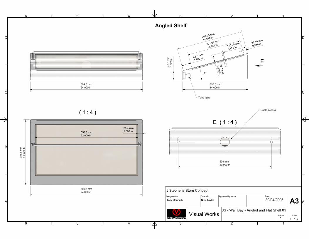
Angled Shelf Angled Shelf
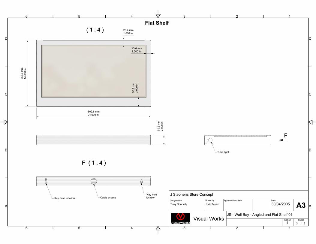
Flat shelf Flat shelf
1
1
2
2
3
3
4
4
5
5
6
6
A A
B B
C C
D D
Designed by Drawn by Approved by - date Date
Edition Sheet
/
J Stephens Store Concept
JS - Wall Bay - Angled and Flat Shelf 01
Visual Works
Tony Donnelly Nick Taylor 30/04/2005
1 1 3
A3
Cable Access
Mounting keyhole
Tube Light
Brushed Nicklefinish
Frosted Acrylicpanel
Heel bar,removable.
Cableaccess
Tube Light
Small locating tubewelded inside forlocating heel bar,prevents rocking.
Mounting key hole
Use a suitable grade of sheet metalso the shelf is ridgid when located to
back board using the 'key hole' fittings,use double thickness to back panel.
Thicken / strengthenthis region to preventwarping when shelfloaded
Thicken / strengthenthis region to preventwarping when shelfloaded
Frosted Acrylicpanel
Brushed Nicklefinish
Use fittings as availablewhich achive a similar
principle to the 'key hole'and 'mushroom head'
fittings.Shelves are mountedflush to back boards
( 1 : 4 ) ( 1 : 4 )
E ( 1 : 4 )E ( 1 : 4 )
1
1
2
2
3
3
4
4
5
5
6
6
A A
B B
C C
D D
Designed by Drawn by Approved by - date Date
Edition Sheet
/
J Stephens Store Concept
JS - Wall Bay - Angled and Flat Shelf 01
Visual Works
Tony Donnelly Nick Taylor 30/04/2005
1 2 3
A3
E
609.6 mm
24.000 in
35
5.6
mm
14
.00
0in
609.6 mm
24.000 in
558.8 mm
22.000 in
48
.5m
m
1.9
09
in
361.93 mm
14.249 in
291.94 mm
11.494 in
48.5 mm
1.909 in
21.49 mm
0.846 in130.08 mm
5.121 in
38.1
mm
1.5
00
in15°
355.6 mm
14.000 in
508 mm
20.000 in
Cable access
Tube light
25.4 mm
1.000 in
Angled Shelf
( 1 : 4 ) ( 1 : 4 )
F ( 1 : 4 )F ( 1 : 4 )
1
1
2
2
3
3
4
4
5
5
6
6
A A
B B
C C
D D
Designed by Drawn by Approved by - date Date
Edition Sheet
/
J Stephens Store Concept
JS - Wall Bay - Angled and Flat Shelf 01
Visual Works
Tony Donnelly Nick Taylor 30/04/2005
1 3 3
A3
F
35
5.6
mm
14
.00
0in
609.6 mm
24.000 in
25.4 mm
1.000 in
25.4 mm
1.000 in
50.8
mm
2.0
00
in
50.8
mm
2.0
00
in
'Key hole' location Cable access'Key hole' location
Flat Shelf
Tube light
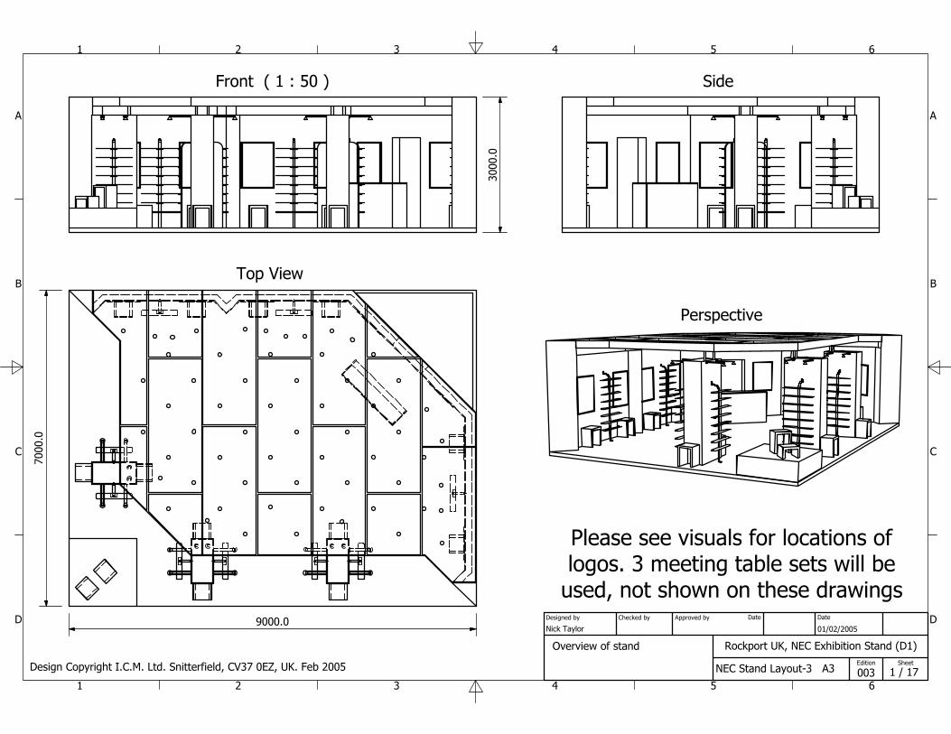
Front ( 1 : 50 )
Top View
Side
Perspective
1
1
2
2
3
3
4
4
5
5
6
6
A A
B B
C C
D D
Rockport UK, NEC Exhibition Stand (D1)
NEC Stand Layout-3 A3
Nick Taylor 01/02/2005
003
Designed by Checked by Approved by Date
1 / 17 Edition Sheet
Date
7000
.0
9000.0
3000
.0
Overview of stand
Please see visuals for locations oflogos. 3 meeting table sets will be
used, not shown on these drawings
Design Copyright I.C.M. Ltd. Snitterfield, CV37 0EZ, UK. Feb 2005
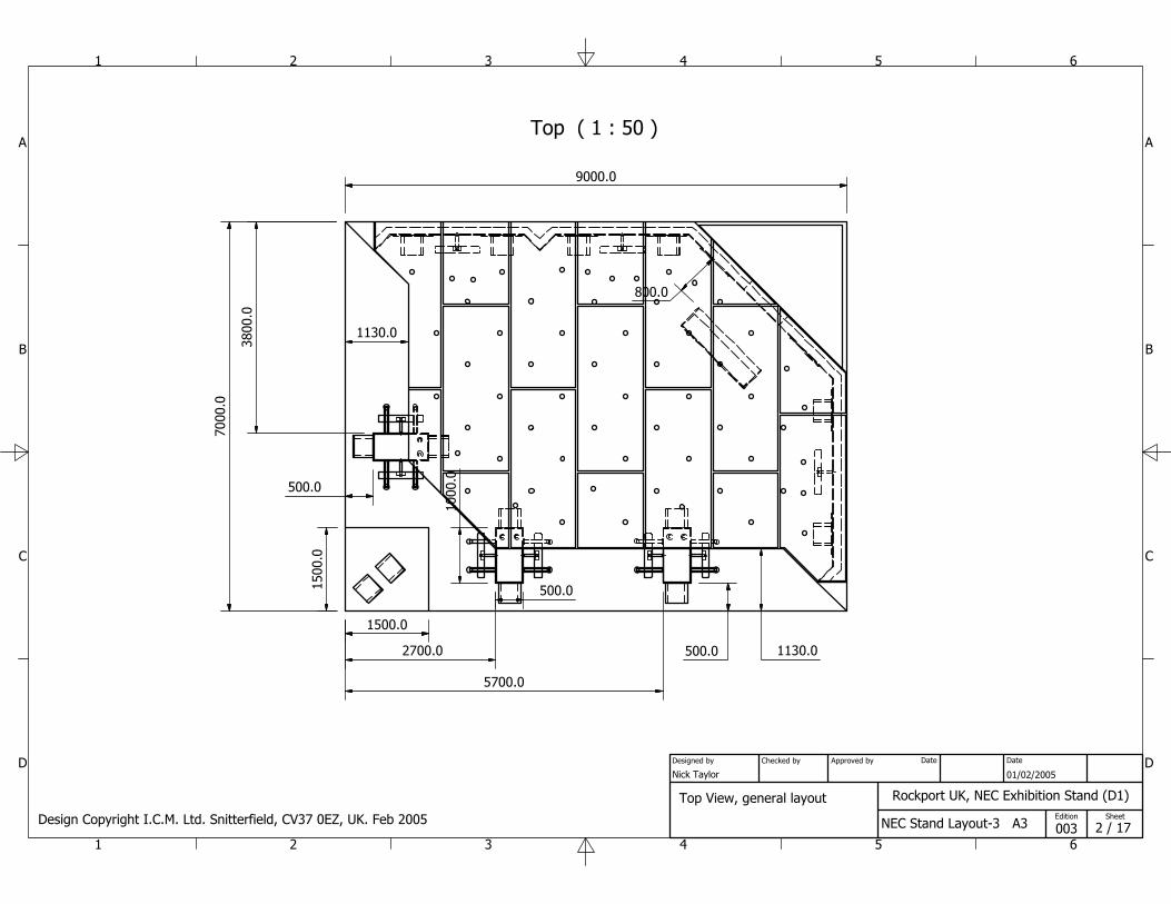
Top ( 1 : 50 )
1
1
2
2
3
3
4
4
5
5
6
6
A A
B B
C C
D D
Rockport UK, NEC Exhibition Stand (D1)
NEC Stand Layout-3 A3
Nick Taylor 01/02/2005
003
Designed by Checked by Approved by Date
2 / 17 Edition Sheet
Date
7000
.0
3800
.0
9000.0
2700.0
5700.0
500.0
1000
.0
500.0
500.0
1130.0
1130.0
800.0
Top View, general layout
1500
.0
1500.0
Design Copyright I.C.M. Ltd. Snitterfield, CV37 0EZ, UK. Feb 2005
View with ceiling removed
1
1
2
2
3
3
4
4
5
5
6
6
A A
B B
C C
D D
Rockport UK, NEC Exhibition Stand (D1)
NEC Stand Layout-3 A3
Nick Taylor 01/02/2005
003
Designed by Checked by Approved by Date
3 / 17 Edition Sheet
Date
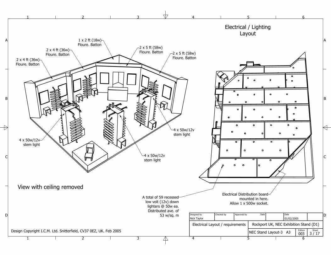
Electrical Layout / requirements
2 x 4 ft (36w)Floure. Batton
2 x 4 ft (36w)Floure. Batton 2 x 5 ft (58w)
Floure. Batton
2 x 5 ft (58w)Floure. Batton
4 x 50w/12vstem light
4 x 50w/12vstem light
4 x 50w/12vstem light
A total of 59 recessedlow volt (12v) downlighters @ 50w ea.Distributed ave. of
53 w/sq. m
Electrical Distribution boardmounted in here.
Allow 1 x 500w socket.
1 x 2 ft (18w)Floure. Batton
Design Copyright I.C.M. Ltd. Snitterfield, CV37 0EZ, UK. Feb 2005
Electrical / LightingLayout
1
1
2
2
3
3
4
4
5
5
6
6
A A
B B
C C
D D
Rockport UK, NEC Exhibition Stand (D1)
NEC Stand Layout-3 A3
Nick Taylor 01/02/2005
003
Designed by Checked by Approved by Date
4 / 17 Edition Sheet
Date
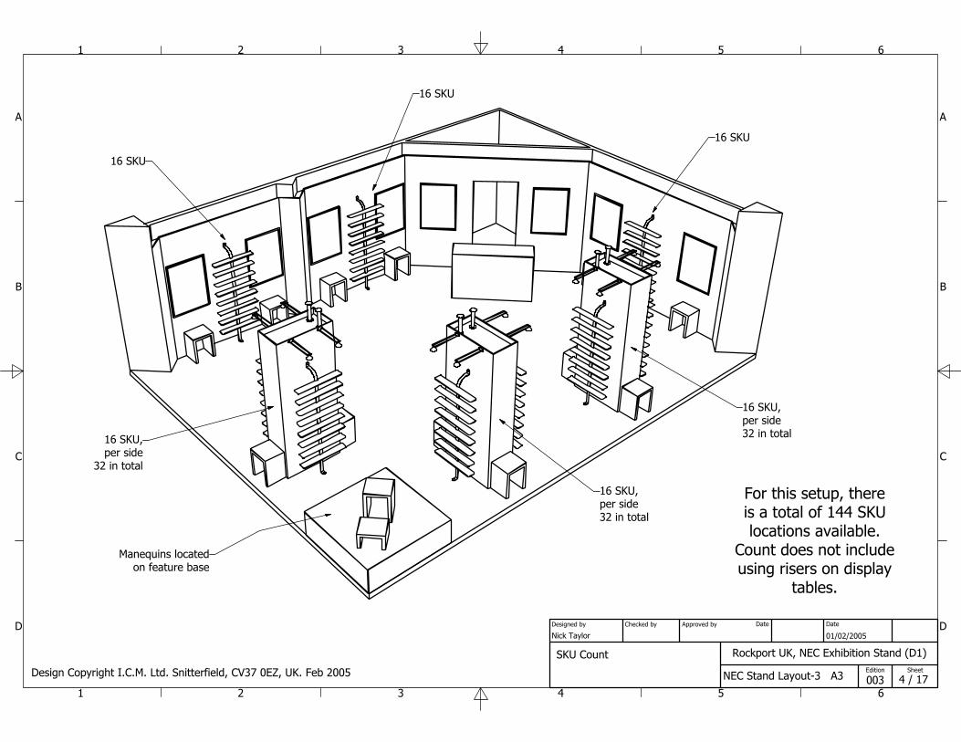
16 SKU
16 SKU
16 SKU
16 SKU,per side
32 in total
16 SKU,per side32 in total
16 SKU,per side32 in total
SKU Count
For this setup, thereis a total of 144 SKUlocations available.
Count does not includeusing risers on display
tables.
Manequins locatedon feature base
Design Copyright I.C.M. Ltd. Snitterfield, CV37 0EZ, UK. Feb 2005
1
1
2
2
3
3
4
4
5
5
6
6
A A
B B
C C
D D
Rockport UK, NEC Exhibition Stand (D1)
NEC Stand Layout-3 A3
Nick Taylor 01/02/2005
003
Designed by Checked by Approved by Date
5 / 17 Edition Sheet
Date
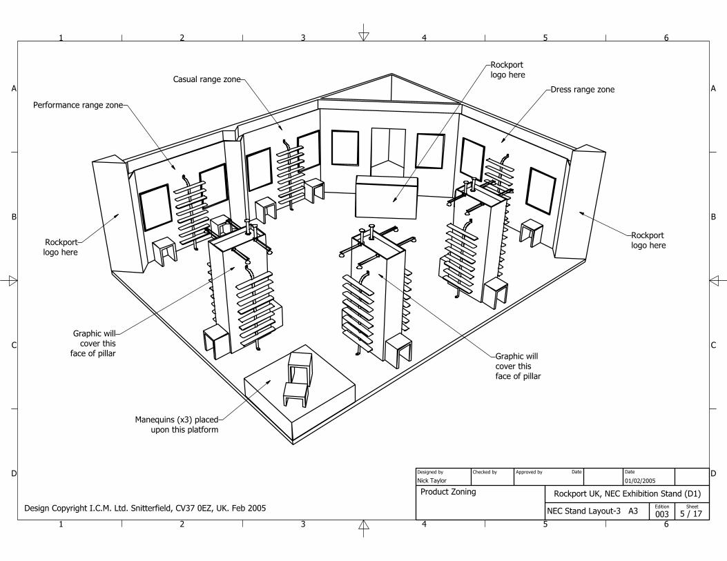
Product Zoning
Performance range zone
Casual range zoneDress range zone
Graphic willcover this
face of pillar Graphic willcover thisface of pillar
Manequins (x3) placedupon this platform
Design Copyright I.C.M. Ltd. Snitterfield, CV37 0EZ, UK. Feb 2005
Rockportlogo here
Rockportlogo here
Rockportlogo here
1
1
2
2
3
3
4
4
5
5
6
6
A A
B B
C C
D D
Rockport UK, NEC Exhibition Stand (D1)
NEC Stand Layout-3 A3
Nick Taylor 01/02/2005
003
Designed by Checked by Approved by Date
6 / 17 Edition Sheet
Date
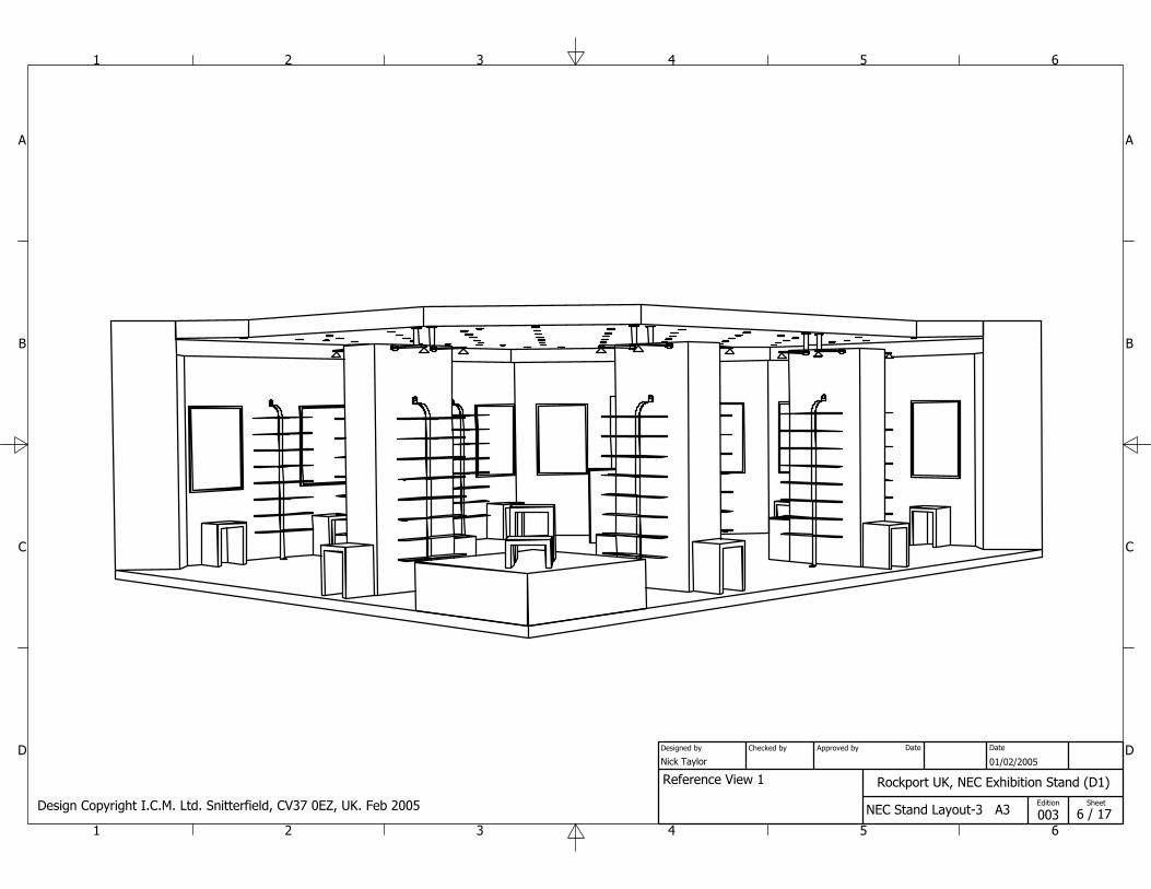
Reference View 1
Design Copyright I.C.M. Ltd. Snitterfield, CV37 0EZ, UK. Feb 2005
1
1
2
2
3
3
4
4
5
5
6
6
A A
B B
C C
D D
Rockport UK, NEC Exhibition Stand (D1)
NEC Stand Layout-3 A3
Nick Taylor 01/02/2005
003
Designed by Checked by Approved by Date
7 / 17 Edition Sheet
Date
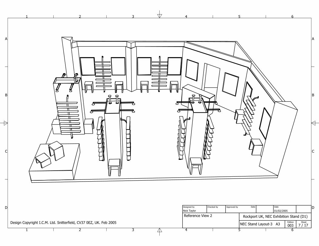
Reference View 2
Design Copyright I.C.M. Ltd. Snitterfield, CV37 0EZ, UK. Feb 2005
1
1
2
2
3
3
4
4
5
5
6
6
A A
B B
C C
D D
Rockport UK, NEC Exhibition Stand (D1)
NEC Stand Layout-3 A3
Nick Taylor 01/02/2005
003
Designed by Checked by Approved by Date
8 / 17 Edition Sheet
Date
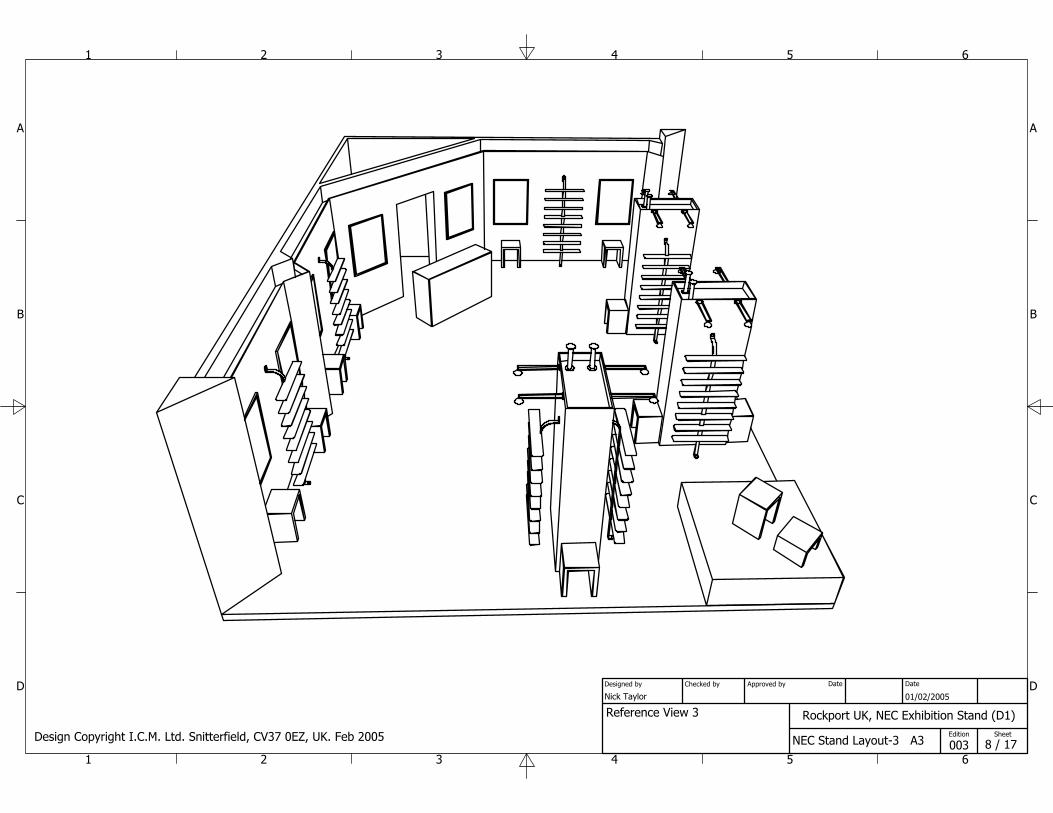
Reference View 3
Design Copyright I.C.M. Ltd. Snitterfield, CV37 0EZ, UK. Feb 2005
Top View ( 1 : 50 )
A-A ( 1 : 50 )
B ( 1 : 25 )
C-C ( 1 : 50 )
1
1
2
2
3
3
4
4
5
5
6
6
A A
B B
C C
D D
Rockport UK, NEC Exhibition Stand (D1)
NEC Stand Layout-3 A3
Nick Taylor 01/02/2005
003
Designed by Checked by Approved by Date
9 / 17 Edition Sheet
Date
A AB
C C
6470
.0
7000
.0
8470.0
9000.0
530.
0
45°250.0
2400.02400.0
3360
.0
45°
530.0
530.0
280.0
100.0
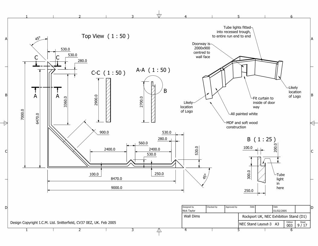
900.0
560.0
530.0
Doorway is2000x900centred to
wall face
Likelylocationof Logo
Tube lights fittedinto recessed trough,
to entire run end to end
Fit curtain toinside of doorway
Likelylocationof Logo
Wall Dims
530.0
280.0
250.0
300.
0
200.
0
100.0
2700
.0
Tubelightinhere
2900
.0
All painted white
Design Copyright I.C.M. Ltd. Snitterfield, CV37 0EZ, UK. Feb 2005
MDF and soft woodconstruction
Pillar Assy ( 1 : 20 )
1
1
2
2
3
3
4
4
5
5
6
6
A A
B B
C C
D D
Rockport UK, NEC Exhibition Stand (D1)
NEC Stand Layout-3 A3
Nick Taylor 01/02/2005
003
Designed by Checked by Approved by Date
10 / 17 Edition Sheet
Date
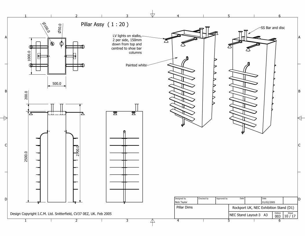
500.0
1000
.025
00.0
200.
0
2700
.0
100.0 50.0 SS Bar and disc
Painted white
Pillar Dims
LV lights on stalks,2 per side, 150mmdown from top andcentred to shoe bar
columns
Design Copyright I.C.M. Ltd. Snitterfield, CV37 0EZ, UK. Feb 2005
1
1
2
2
3
3
4
4
5
5
6
6
A A
B B
C C
D D
Rockport UK, NEC Exhibition Stand (D1)
NEC Stand Layout-3 A3
Nick Taylor 01/02/2005
003
Designed by Checked by Approved by Date
11 / 17 Edition Sheet
Date
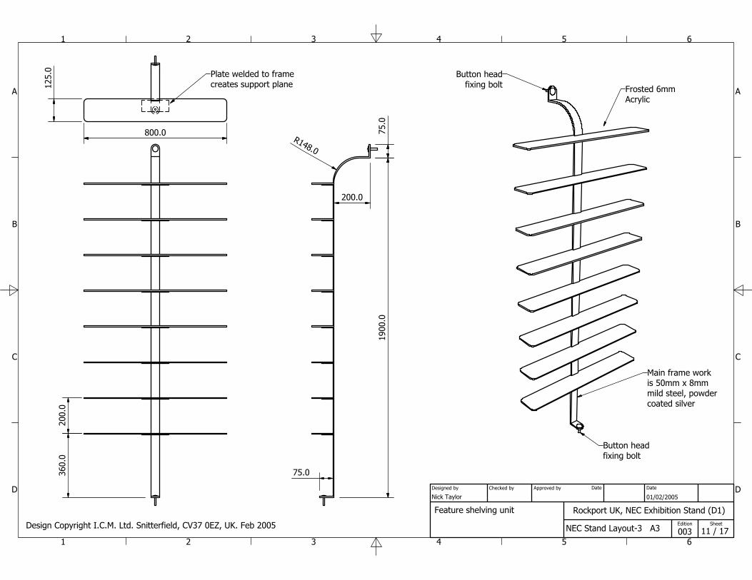
Feature shelving unit
Button headfixing bolt
Button headfixing bolt
Frosted 6mmAcrylic
Main frame workis 50mm x 8mmmild steel, powdercoated silver
125.
0
800.0R148.0
1900
.075
.0
75.0360.
020
0.0
Plate welded to framecreates support plane
200.0
Design Copyright I.C.M. Ltd. Snitterfield, CV37 0EZ, UK. Feb 2005
1
1
2
2
3
3
4
4
5
5
6
6
A A
B B
C C
D D
Rockport UK, NEC Exhibition Stand (D1)
NEC Stand Layout-3 A3
Nick Taylor 01/02/2005
003
Designed by Checked by Approved by Date
12 / 17 Edition Sheet
Date
5743.6
530.0
1130
.0
4300
.0
5870
.0
8470.0
2726
.5
6470
.0
530.0
1130.0
6300.0
7870.0
135°
135°
200.0
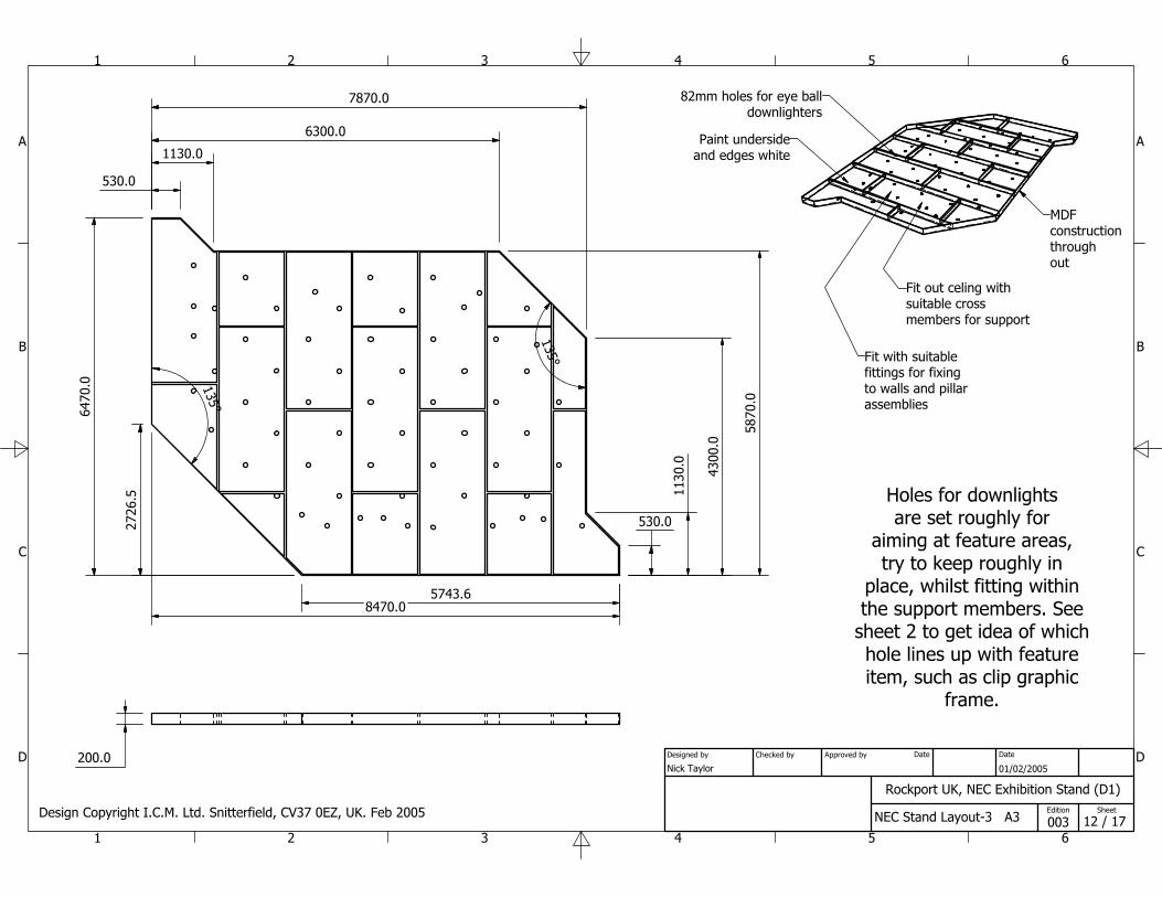
Fit out celing withsuitable crossmembers for support
Holes for downlightsare set roughly for
aiming at feature areas,try to keep roughly in
place, whilst fitting withinthe support members. See
sheet 2 to get idea of whichhole lines up with featureitem, such as clip graphic
frame.
Paint undersideand edges white
Fit with suitablefittings for fixingto walls and pillarassemblies
82mm holes for eye balldownlighters
MDFconstructionthroughout
Design Copyright I.C.M. Ltd. Snitterfield, CV37 0EZ, UK. Feb 2005
( 0.03 : 1 )
1
1
2
2
3
3
4
4
5
5
6
6
A A
B B
C C
D D
Rockport UK, NEC Exhibition Stand (D1)
NEC Stand Layout-3 A3
Nick Taylor 01/02/2005
003
Designed by Checked by Approved by Date
13 / 17 Edition Sheet
Date
3133.3
899.8
1022.11041.5
1436.2
870.5
1102.8
2001.9
2567.6
3699.0
4161.4
4830.34830.3
5103.6
5396.0 5600.6
4876.74876.7
4329.64329.6
3338.43338.4
674.
9
1107
.011
07.0
1379
.213
79.2
1672
.716
72.7
1763
.8
2291
.922
91.9
2804
.128
04.1
3369
.833
69.8
3829
.538
29.5
3935
.542
68.5
4268
.545
01.1
5066
.850
66.8
4693
.1
5281
.4
5742
.1
6198
.2
6763
.9
7387
.2
7712
.4
7698
.1
1034.4
7329
.6
1489
.1
2530
.9
5511
.056
32.5
2238
.4
4264.7
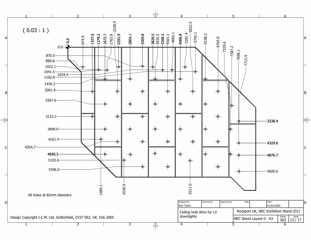
All holes at 82mm diametre
0.0
0.0
0.0
Design Copyright I.C.M. Ltd. Snitterfield, CV37 0EZ, UK. Feb 2005Ceiling hole dims for LV downlights
( 1 : 10 )
1
1
2
2
3
3
4
4
5
5
6
6
A A
B B
C C
D D
Rockport UK, NEC Exhibition Stand (D1)
NEC Stand Layout-3 A3
Nick Taylor 01/02/2005
003
Designed by Checked by Approved by Date
14 / 17 Edition Sheet
Date
1600.0
1000
.0
450.
0
300.0410.
0
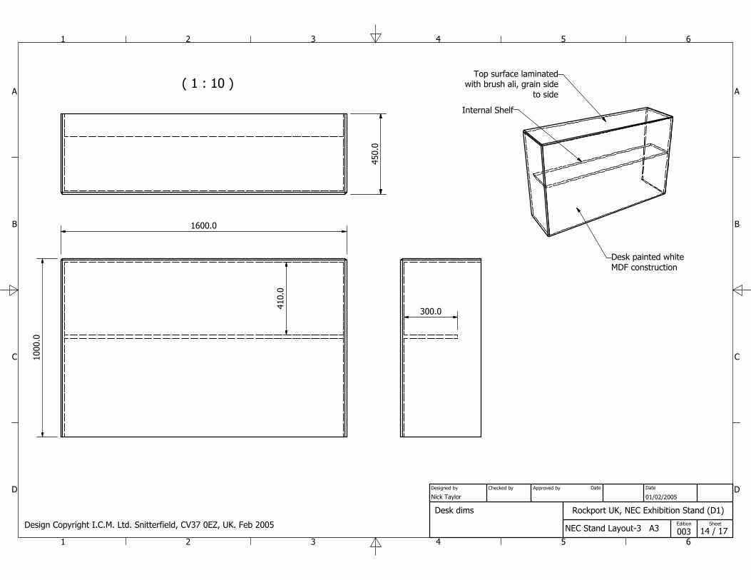
Desk painted whiteMDF construction
Desk dims
Internal Shelf
Top surface laminatedwith brush ali, grain side
to side
Design Copyright I.C.M. Ltd. Snitterfield, CV37 0EZ, UK. Feb 2005
1
1
2
2
3
3
4
4
5
5
6
6
A A
B B
C C
D D
Rockport UK, NEC Exhibition Stand (D1)
NEC Stand Layout-3 A3
Nick Taylor 01/02/2005
003
Designed by Checked by Approved by Date
15 / 17 Edition Sheet
Date
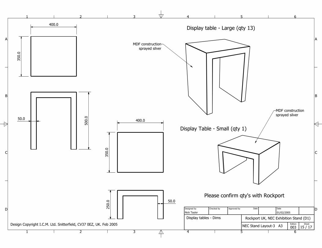
400.0
350.
0
500.
050.0 400.0
350.
025
0.0 50.0
MDF constructionsprayed silver
MDF constructionsprayed silver
Display table - Large (qty 13)
Display Table - Small (qty 1)
Please confirm qty's with Rockport
Display tables - Dims
Design Copyright I.C.M. Ltd. Snitterfield, CV37 0EZ, UK. Feb 2005
1
1
2
2
3
3
4
4
5
5
6
6
A A
B B
C C
D D
Rockport UK, NEC Exhibition Stand (D1)
NEC Stand Layout-3 A3
Nick Taylor 01/02/2005
003
Designed by Checked by Approved by Date
16 / 17 Edition Sheet
Date
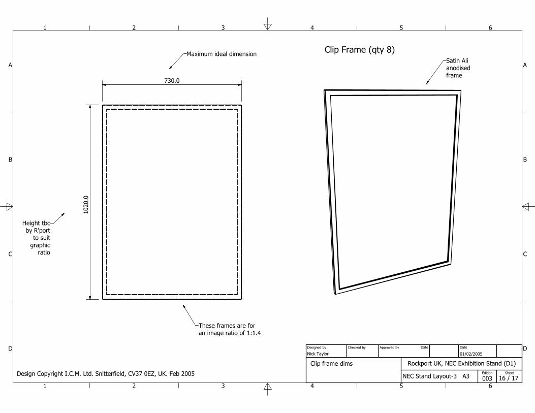
730.010
20.0
Clip Frame (qty 8)Maximum ideal dimension
Height tbcby R'port
to suitgraphic
ratio
Satin Alianodisedframe
Clip frame dims
Design Copyright I.C.M. Ltd. Snitterfield, CV37 0EZ, UK. Feb 2005
These frames are foran image ratio of 1:1.4
1
1
2
2
3
3
4
4
5
5
6
6
A A
B B
C C
D D
Rockport UK, NEC Exhibition Stand (D1)
NEC Stand Layout-3 A3
Nick Taylor 01/02/2005
003
Designed by Checked by Approved by Date
17 / 17 Edition Sheet
Date
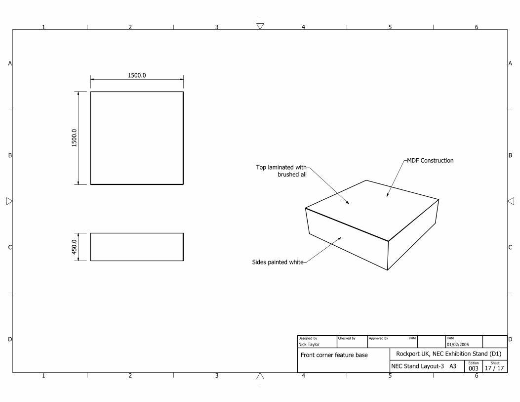
1500
.01500.0
450.
0
Sides painted white
Top laminated withbrushed ali
Front corner feature base
MDF Construction
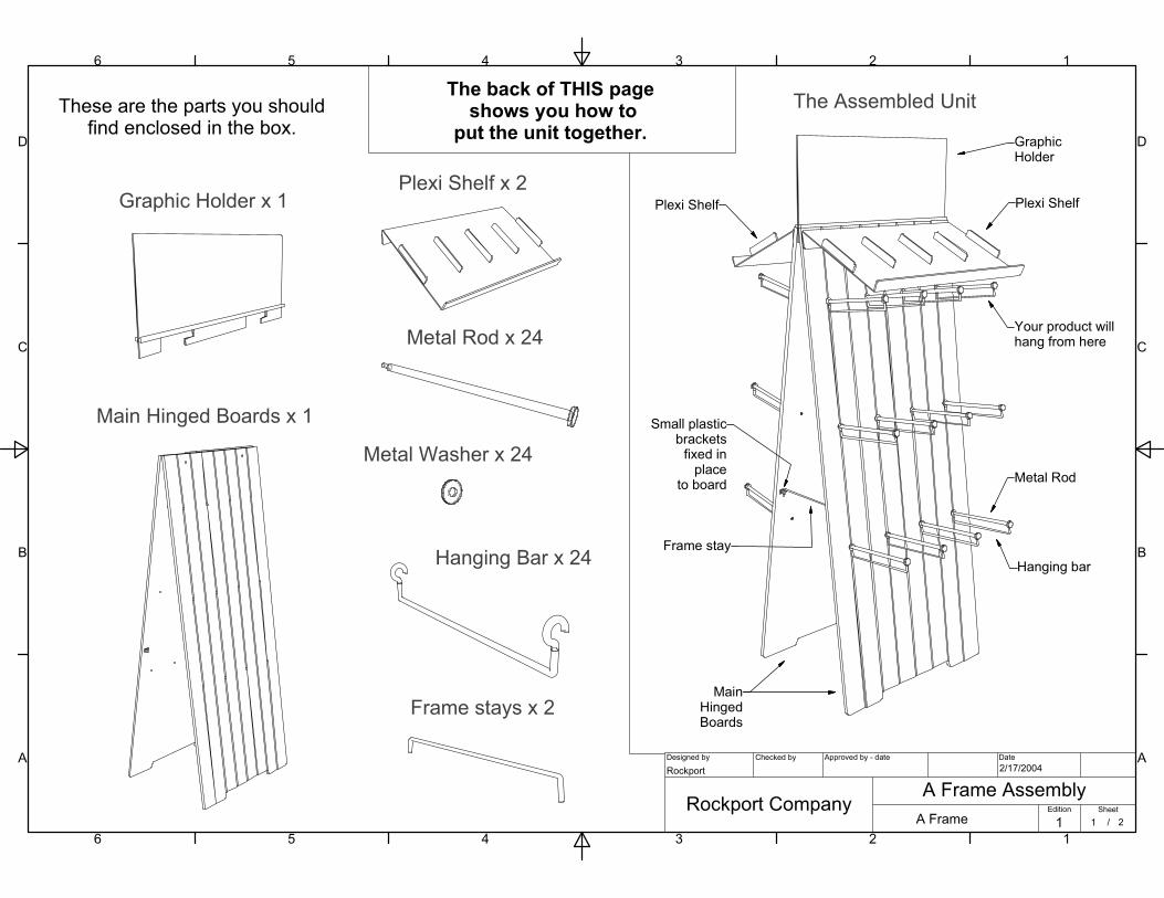
The Assembled Unit
Main Hinged Boards x 1
Plexi Shelf x 2 Graphic Holder x 1
Metal Rod x 24
Hanging Bar x 24
Frame stays x 2
Metal Washer x 24
1
1
2
2
3
3
4
4
5
5
6
6
A A
B B
C C
D D
Designed by Checked by Approved by - date Date
Edition Sheet
/
A Frame AssemblyA Frame
Rockport Company
Rockport 2/17/2004
1 1 2
These are the parts you shouldfind enclosed in the box.
Plexi Shelf Plexi Shelf
Frame stay
Metal Rod
Hanging bar
GraphicHolder
MainHingedBoards
The back of THIS page shows you how to
put the unit together.
Your product willhang from here
Small plasticbrackets
fixed inplace
to board
1
1
2
2
3
3
4
4
5
5
6
6
A A
B B
C C
D D
Designed by Checked by Approved by - date Date
Edition Sheet
/
A Frame AssemblyA Frame
Rockport Company
Rockport 2/17/2004
1 2 2
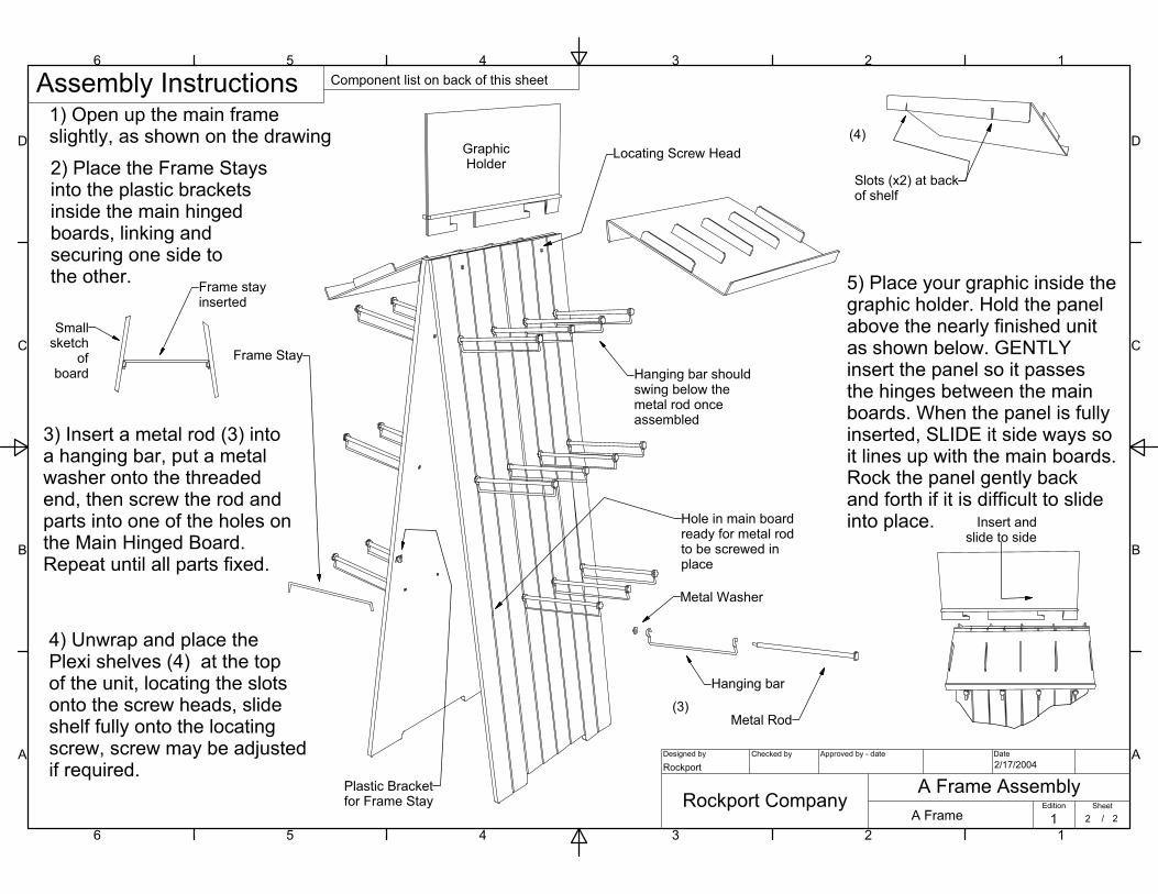
1) Open up the main frameslightly, as shown on the drawing
3) Insert a metal rod (3) intoa hanging bar, put a metalwasher onto the threadedend, then screw the rod andparts into one of the holes onthe Main Hinged Board.Repeat until all parts fixed.
Slots (x2) at backof shelf
4) Unwrap and place thePlexi shelves (4) at the topof the unit, locating the slotsonto the screw heads, slideshelf fully onto the locatingscrew, screw may be adjustedif required.
Locating Screw Head
Frame Stay
Plastic Bracketfor Frame Stay
Metal Rod
Hanging bar
Metal Washer
Hanging bar shouldswing below the metal rod onceassembled
Hole in main boardready for metal rodto be screwed inplace
2) Place the Frame Staysinto the plastic bracketsinside the main hingedboards, linking andsecuring one side tothe other. Frame stay
inserted
Smallsketch
ofboard
Insert andslide to side
5) Place your graphic inside thegraphic holder. Hold the panelabove the nearly finished unitas shown below. GENTLYinsert the panel so it passesthe hinges between the mainboards. When the panel is fullyinserted, SLIDE it side ways soit lines up with the main boards.Rock the panel gently backand forth if it is difficult to slideinto place.
(3)
(4)GraphicHolder
Assembly Instructions Component list on back of this sheet
( 0.17 : 1 )
A ( 1 : 1 )
B ( 1 : 2 )
E ( 3 : 4 )
1
1
2
2
3
3
4
4
5
5
6
6
7
7
8
8
9
9
10
10
11
11
12
12
A A
B B
C C
D D
E E
F F
G G
H H
Designed by Checked by Approved by - date Date
Edition Sheet
/
A1Jamacia Series
A Frame Assembly 01Quadraco Ltd.
Nick Taylor09/01/2004
2 1 5
F:\Clients\2 2 Quadraco Internal\Rockport by Quadraco\Rockport by Quadraco\Workgroup\Jamacia Sandal A frame\A Frame Assembly 01.iam
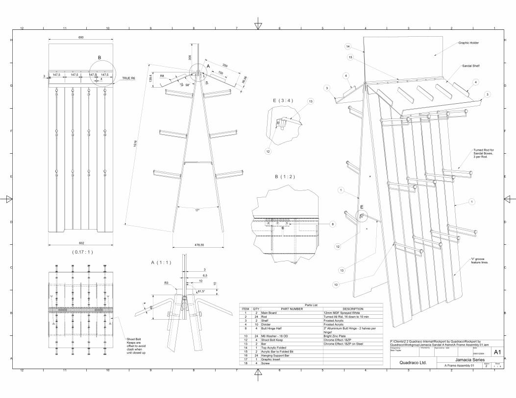
1 2 Main Board 12mm MDF Sprayed White2 24 Rod Turned Ali Rid, 16 down to 10 min3 2 Shelf Frosted Acrylic4 10 Divider Frosted Acrylic8 4 Butt Hinge Half 3" Alluminium Butt Hinge - 2 halves per
hinge!10 24 M6 Washer - 18 OD Bright Zinc Plate12 4 Shoot Bolt Keep Chrome Effect / BZP13 2 Bar Chrome Effect / BZP on Steel14 1 Top Acrylic Folded15 2 Acrylic Bar to Folded Bit16 24 Hanging Support Bar17 1 Graphic Insert18 4 Screw
Parts ListITEM QTY PART NUMBER DESCRIPTION
A
B
E
602
1516
300
150
350
36,0
6
25
45
17°
478,55
Graphic Holder
Sandal Shelf
Turned Rod for Sandal Boxes,3 per Rod.
'V' groovefeature lines.
14
4
3
4
3
1
1
15
6,5
3
10
40
4
3 147,5 147,5 147,5 147,54 TRUE R6
R8
58°
139,
4
81,5°
8
13
12
10
13
12
Shoot BoltKeeps areoffset to avoidclash whenunit closed up
600
R3 10
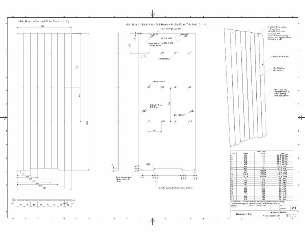
Main Board - Grooved Side / Front ( 1 : 4 )Main Board - Back Side - Drill Holes + Profile From This Side ( 1 : 4 )
1
1
2
2
3
3
4
4
5
5
6
6
7
7
8
8
9
9
10
10
11
11
12
12
A A
B B
C C
D D
E E
F F
G G
H H
Designed by Checked by Approved by - date Date
Edition Sheet
/
A1Jamacia Series
A Frame Assembly 01Quadraco Ltd.
Nick Taylor09/01/2004
2 2 5
F:\Clients\2 2 Quadraco Internal\Rockport by Quadraco\Rockport by Quadraco\Workgroup\Jamacia Sandal A frame\Main Board.ipt
602
76 75 75 75 75 75 75 76
76151
226301
376451
526602
600
981
1516
6 312
25
Spray Painted White
M6 'T' Nuts x 12Inserted from Back,before painting(non grooved side)
12 x Rods fixedafter painting
2 x Shelf fixing screws+ 4mm Spacerplaced in these holeson groove sideto suit thickness of plexi,appox. 4mm gap below headto surface of MDF
8 THRU12x
2,5 THRU2x
2,5 -9 DEEP
R10
16
A1 A2 A3 A4 A5 A6B1 B2
C1C2 C3C4
D1 D2 D3 D4
D5 D6 D7 D8
D9 D10 D11 D12
Hole TableLOC XDIM YDIM SIZE
A1 104 -16 2,5 -9 DEEPA2 134 -16 2,5 -9 DEEPA3 164 -16 2,5 -9 DEEPA4 438 -16 2,5 -9 DEEPA5 468 -16 2,5 -9 DEEPA6 498 -16 2,5 -9 DEEPB1 117 -34 2,5 THRUB2 485 -34 2,5 THRUC1 18,5 -865,66 2 -6 DEEPC2 36,5 -865,66 2 -6 DEEPC3 545,5 -865,66 2 -6 DEEPC4 563,5 -865,66 2 -6 DEEPD1 76 -219 8 THRUD2 226 -219 8 THRUD3 376 -219 8 THRUD4 526 -219 8 THRUD5 76 -600 8 THRUD6 226 -600 8 THRUD7 376 -600 8 THRUD8 526 -600 8 THRUD9 76 -981 8 THRUD10 226 -981 8 THRUD11 376 -981 8 THRUD12 526 -981 8 THRU
2 -6 DEEP
0 10 136
146
156
446
456
466
592
602
Dims for quadrants of each radius @ 10mm
0
150115061516
Dims for quadrantsof each radius @10mm
Holes for Rods
Holes for ShootBolt Keep
Holes for Hinge Alignment
Holes for ShelfLocating Screw
150
381
219
76
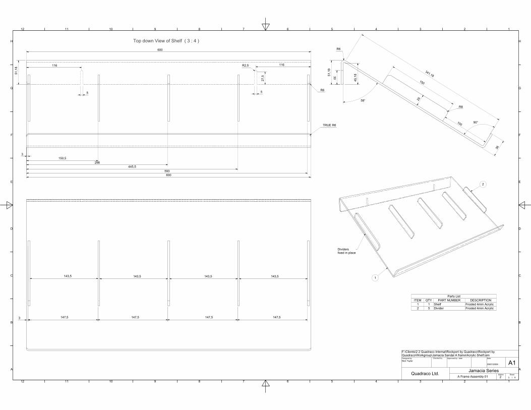
Top down View of Shelf ( 3 : 4 )
1
1
2
2
3
3
4
4
5
5
6
6
7
7
8
8
9
9
10
10
11
11
12
12
A A
B B
C C
D D
E E
F F
G G
H H
Designed by Checked by Approved by - date Date
Edition Sheet
/
A1Jamacia Series
A Frame Assembly 01Quadraco Ltd.
Nick Taylor09/01/2004
2 3 5
F:\Clients\2 2 Quadraco Internal\Rockport by Quadraco\Rockport by Quadraco\Workgroup\Jamacia Sandal A frame\Acrylic Shelf.iam
1 1 Shelf Frosted 4mm Acrylic2 5 Divider Frosted 4mm Acrylic
Parts ListITEM QTY PART NUMBER DESCRIPTION
150
25
R8
51,1
9
45,1
8
58°
90°
341,18
100
36
600
116 116
51,1
8
R6
TRUE R6
R6
30
27,5
R2,5
55
3150,5
298445,5
593600
143,5 143,5 143,5 143,5
147,5 147,5147,5147,53
1
2
Dividersfixed in place
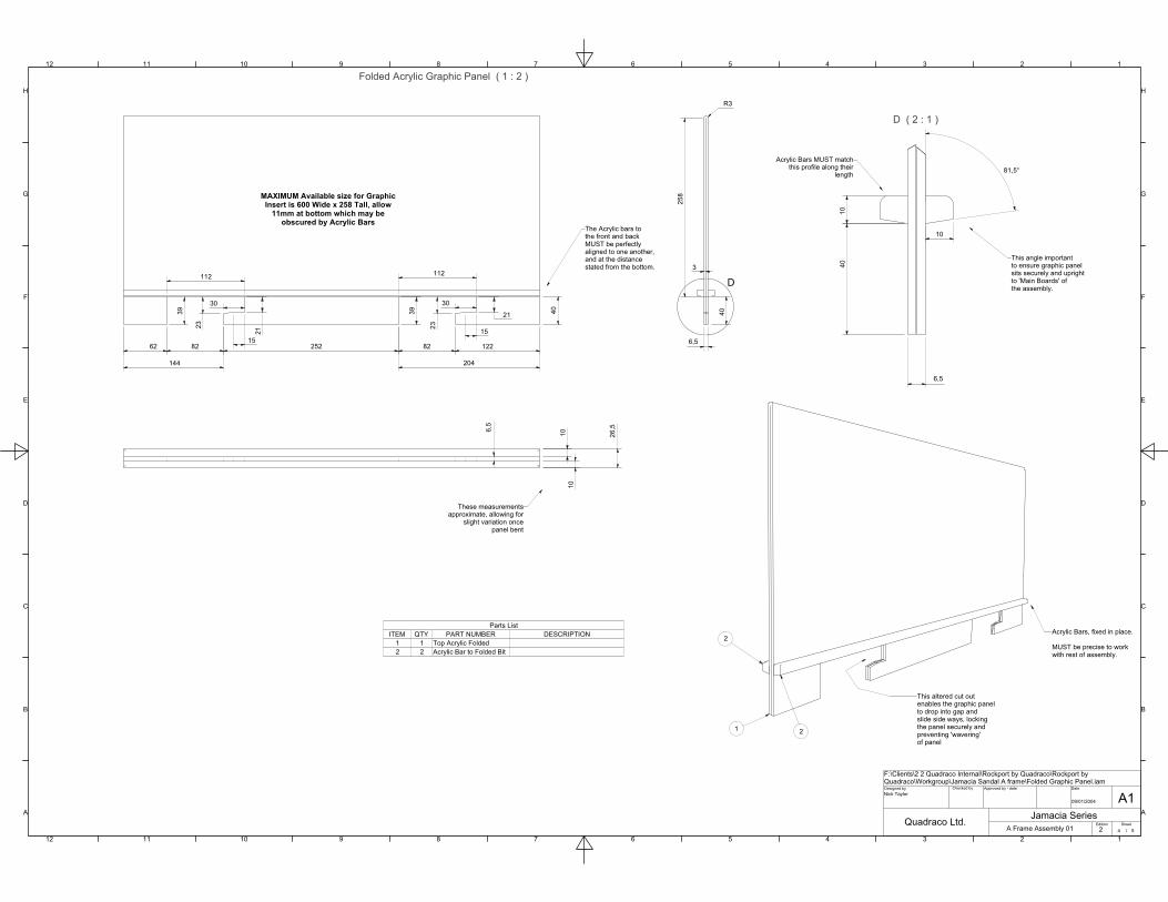
Folded Acrylic Graphic Panel ( 1 : 2 )
D ( 2 : 1 )
1
1
2
2
3
3
4
4
5
5
6
6
7
7
8
8
9
9
10
10
11
11
12
12
A A
B B
C C
D D
E E
F F
G G
H H
Designed by Checked by Approved by - date Date
Edition Sheet
/
A1Jamacia Series
A Frame Assembly 01Quadraco Ltd.
Nick Taylor09/01/2004
2 4 5
F:\Clients\2 2 Quadraco Internal\Rockport by Quadraco\Rockport by Quadraco\Workgroup\Jamacia Sandal A frame\Folded Graphic Panel.iam
1 1 Top Acrylic Folded2 2 Acrylic Bar to Folded Bit
Parts ListITEM QTY PART NUMBER DESCRIPTION
D
2
Acrylic Bars, fixed in place.
MUST be precise to workwith rest of assembly.
8262 252 82 122
144 204
39 40 40
6,5
3
6,5
10
This angle importantto ensure graphic panelsits securely and uprightto 'Main Boards' ofthe assembly.
The Acrylic bars tothe front and backMUST be perfectlyaligned to one another,and at the distancestated from the bottom.
Acrylic Bars MUST matchthis profile along their
length
These measurementsapproximate, allowing for
slight variation oncepanel bent
258MAXIMUM Available size for Graphic
Insert is 600 Wide x 258 Tall, allow11mm at bottom which may be
obscured by Acrylic Bars
R3
1040
81,5°
2
1
26,5
1010
6,5
23
21
15
30
112 112
39
23
21
15
30
This altered cut outenables the graphic panelto drop into gap andslide side ways, lockingthe panel securely andpreventing 'wavering'of panel
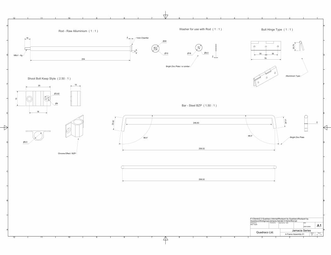
Rod - Raw Alluminium ( 1 : 1 ) Washer for use with Rod ( 1 : 1 ) Butt Hinge Type ( 1 : 1 )
Bar - Steel BZP ( 1.50 : 1 )
Shoot Bolt Keep Style ( 2.50 : 1 )
1
1
2
2
3
3
4
4
5
5
6
6
7
7
8
8
9
9
10
10
11
11
12
12
A A
B B
C C
D D
E E
F F
G G
H H
Designed by Checked by Approved by - date Date
Edition Sheet
/
A1Jamacia Series
A Frame Assembly 01Quadraco Ltd.
Nick Taylor09/01/2004
2 5 5
F:\Clients\2 2 Quadraco Internal\Rockport by Quadraco\Rockport by Quadraco\Workgroup\Jamacia Sandal A frame\Rod.ipt
254
14
M6x1 - 6g
20
10
1mm Chamfer
182
6,5
76
30 30
Alluminium Type
246,83
98,5°98,5°
22,4
2
17,42
258,52
258,52
5
25
15
18
8,5
10
3,62
6
Bright Zinc Plate
Chrome Effect / BZP
Bright Zinc Plate / or similar
5
4
20,7
5