Embed Size (px)
Citation preview
3D MANUFACTURING SIMULATION – IMPROVING THE RETURN ON INVESTMENT
Mika AnttilaVisual Components Oy
Korppaanmäentie 17 CL 6, 00300 Helsinki, FinlandE-mail: [email protected]
KEYWORDS3D manufacturing simulation, cost effective, componentmodels
ABSTRACT
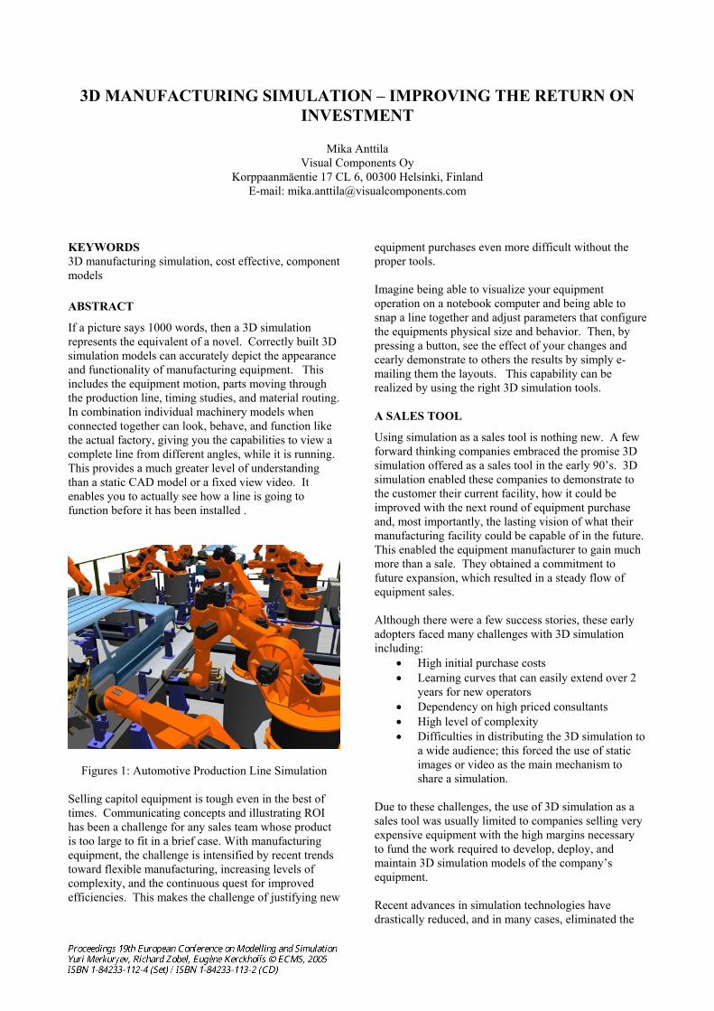
If a picture says 1000 words, then a 3D simulationrepresents the equivalent of a novel. Correctly built 3D simulation models can accurately depict the appearance and functionality of manufacturing equipment. Thisincludes the equipment motion, parts moving throughthe production line, timing studies, and material routing.In combination individual machinery models when connected together can look, behave, and function likethe actual factory, giving you the capabilities to view a complete line from different angles, while it is running.This provides a much greater level of understandingthan a static CAD model or a fixed view video. Itenables you to actually see how a line is going to function before it has been installed .
Figures 1: Automotive Production Line Simulation
Selling capitol equipment is tough even in the best of times. Communicating concepts and illustrating ROI has been a challenge for any sales team whose productis too large to fit in a brief case. With manufacturingequipment, the challenge is intensified by recent trends toward flexible manufacturing, increasing levels of complexity, and the continuous quest for improvedefficiencies. This makes the challenge of justifying new
equipment purchases even more difficult without theproper tools.
Imagine being able to visualize your equipmentoperation on a notebook computer and being able tosnap a line together and adjust parameters that configurethe equipments physical size and behavior. Then, bypressing a button, see the effect of your changes and cearly demonstrate to others the results by simply e-mailing them the layouts. This capability can berealized by using the right 3D simulation tools.
A SALES TOOL
Using simulation as a sales tool is nothing new. A few forward thinking companies embraced the promise 3D simulation offered as a sales tool in the early 90’s. 3D simulation enabled these companies to demonstrate tothe customer their current facility, how it could beimproved with the next round of equipment purchase and, most importantly, the lasting vision of what theirmanufacturing facility could be capable of in the future.This enabled the equipment manufacturer to gain muchmore than a sale. They obtained a commitment to future expansion, which resulted in a steady flow of equipment sales.
Although there were a few success stories, these early adopters faced many challenges with 3D simulationincluding:
High initial purchase costsLearning curves that can easily extend over 2 years for new operators Dependency on high priced consultantsHigh level of complexityDifficulties in distributing the 3D simulation toa wide audience; this forced the use of static images or video as the main mechanism to share a simulation.
Due to these challenges, the use of 3D simulation as a sales tool was usually limited to companies selling veryexpensive equipment with the high margins necessaryto fund the work required to develop, deploy, and maintain 3D simulation models of the company’sequipment.
Recent advances in simulation technologies have drastically reduced, and in many cases, eliminated the
challenges faced by the early adopters. Thus, allowing 3D simulation to be deployed on a much larger scale byequipment manufactures. These advancements include:
1. Applying component modelling techniques to simulation models so that a plug-and-playworks for connecting equipment together and drastically simplifies the task of line layouts.
2. Encapsulating the complexity within a component to facilitate re-use and streamlinemaintainability.
3. Simulation products that are layered for different user levels throughout theorganization. The most basic of which can be easily used by anyone with basic computerskills.
4. The reduction in purchase price of theproducts.
5. Advancements in computer and softwareperformance enabling interactive performanceon laptop PC’s.
The origins of factory simulation began in the 70’s, with the products that were mainly statistical in nature.These products took numbers from timing studies, as input and output reports, enabling the industrialengineer to run experiments in order to determine whichmethods could improve the manufacturing process.Very quickly, these products evolved to include 2D charts and graphs. This technology was called “discreteevent simulation” because of the way that manufacturing processes were approximated into singletime taking events. This approximation made itpossible for entire factories to be simulated on computers that were very slow by today’s standards.
The 80’s brought a new generation of simulation whichis sometimes referred to as “physics based” todistinguish it from discrete event. These products were initially targeted at the Robotics market. They offered the ability to accurately simulate the motion of robots, check for collisions, and simulate the effects of inertiabased on payload. The key advancement of theseproducts is that they were completely 3D based. There were a number of success stories using these productsfor sales presentations and proposals due to the realisticnature of the 3D display.
Advancements of the 90’s included a trend to provide3D graphics capabilities in discrete event simulationproducts. Unfortunately, the simulation engine used bythese products did not contain the accurate motion that was common in the physics based robotic simulationcounterparts. While this technology proved effective inidentifying bottlenecks and optimizing throughput, it did little to give the customer a clear picture of whatthey were purchasing and why.
The most recent advancements include the combinationof physics based simulation and discrete eventtechnology within the same product. This provides theideal platform for the sales proposal market, since manyof the key decision-makers in large-scale factory installations are non-technical in nature. These productsprovides a conduit for effective communicationincluding:
1. Communicating new ideas and concepts to a customer thereby obtaining commitment earlier
2. Describing the competitive advantages of yourequipment
3. Justifying value4. Understanding what is being purchased and
why
The use of 3D simulation does not stop once the order isreceived. It provides benefits that extend from the supplier, to the line integrator, and to the end user. By leveraging the model throughout the business process, a large cost savings can be realized, much more than if just the engineering department use simulation tocomplete layout and process design analysis.
COMPLETE PRODUCTION LIFECYCLE SUPPORT
3D manufacturing simulation can support the completeproduction lifecycle from the early product designs tothe re-configuration of production. 3D simulation can be used in all these steps as a communication tool to convey the idea of how a production works and how itperforms to avoid costly mistakes as early as possible. Easier communication speeds up the decision makingprocess creating better results faster.
In the early product development phase 3D simulationcan be integrated into the design process in order to see the working product with performance data. This easiervirtual prototyping supports the testing of a greaterrange of alternatives instead of settling into the first found solution found.
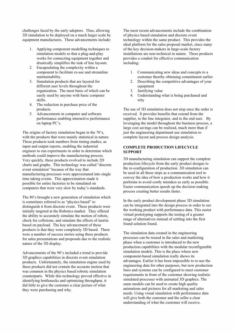
The simulation data created in the engineering processes can be reused in the sales and marketingphase when a customer is introduced to the new production capabilities with the modular reconfigurable simulation models. This is the place where new component-based simulation really shows itsadvantages. Earlier it has been impossible to re-use theengineering data for other purposes, but now productionlines and systems can be configured to meet customerrequirements in front of the customer showing realisticsimulated processes with animated 3D graphics. The same models can be used to create high qualityanimations and pictures for all marketing and salesneeds. Using visual simulation with performance datawill give both the customer and the seller a clear understanding of what the customer will receive.
Figures 2: Reconfigurable Simulation Sales Model
Once a production system goes into the implementation phase, previously created simulation models can be used for verifying the line control logic to speed up the ramp up phase. This creates other possibilities to use the same simulation model for training purposes before the actual system is up and running. All this is achieved by using the simulation model as a virtual test bench that is connected to real control systems via a COM interface.
During production, the simulation model can be used for every day planning to validate and optimize production orders in advance. The simulation model may also serve as a 3D interface to the real system for monitoring and remote diagnostic purposes.
At the end of the production lifecycle, the simulation model can be reconfigured to meet the new production requirements.
SAY GOOD-BYE TO EXPENSIVE, ONE-OFF SIMULATIONS
One-off simulation models built from scratch by a dedicated simulation engineer are expensive and used mostly for engineering purposes. The new component based simulation model approach re-uses simulation components allowing non-engineers to build simulation models quickly to meet many other needs within an organsiation.
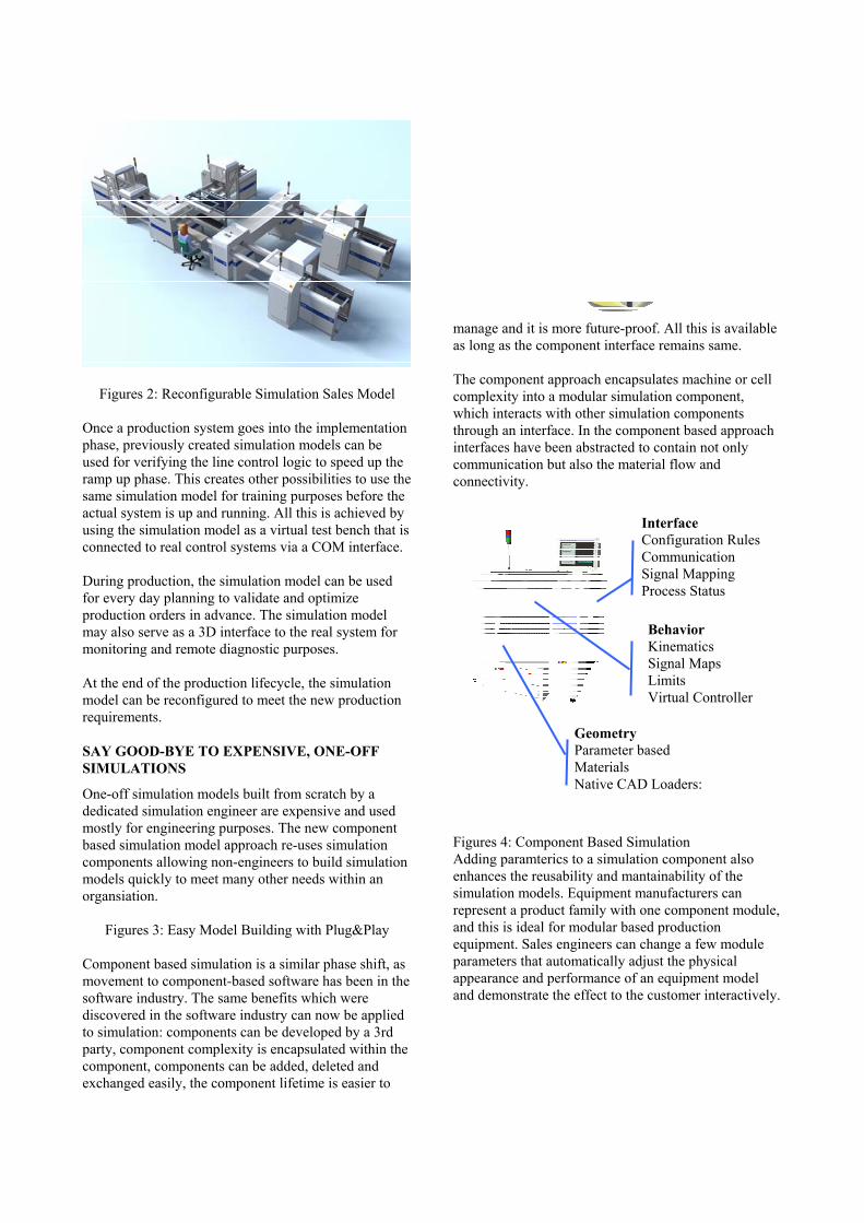
Figures 3: Easy Model Building with Plug&Play
Component based simulation is a similar phase shift, as movement to component-based software has been in the software industry. The same benefits which were discovered in the software industry can now be applied to simulation: components can be developed by a 3rd party, component complexity is encapsulated within the component, components can be added, deleted and exchanged easily, the component lifetime is easier to
manage and it is more future-proof. All this is available as long as the component interface remains same.
The component approach encapsulates machine or cell complexity into a modular simulation component, which interacts with other simulation components through an interface. In the component based approach interfaces have been abstracted to contain not only communication but also the material flow and connectivity.
Figures 4: Component Based Simulation Adding paramterics to a simulation component also enhances the reusability and mantainability of the simulation models. Equipment manufacturers can represent a product family with one component module, and this is ideal for modular based production equipment. Sales engineers can change a few module parameters that automatically adjust the physical appearance and performance of an equipment model and demonstrate the effect to the customer interactively.
Behavior Kinematics Signal Maps Limits Virtual Controller
GeometryParameter based Materials Native CAD Loaders:
InterfaceConfiguration RulesCommunication Signal Mapping Process Status
ROBOTICS AND MATERIAL HANDLING ON THE ONE PLATFORM
The new behavior based component modeling approach now makes it possible to use the same simulationplatform for robotics and material handling.
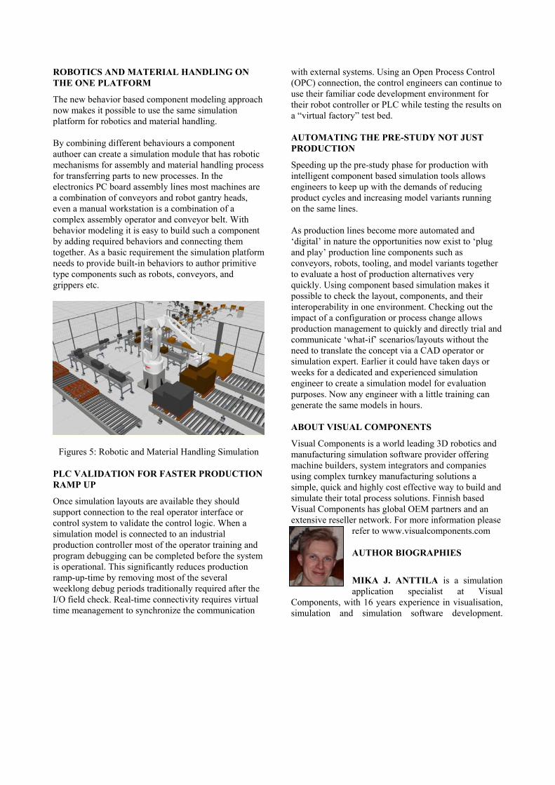
By combining different behaviours a componentauthoer can create a simulation module that has roboticmechanisms for assembly and material handling process for transferring parts to new processes. In the electronics PC board assembly lines most machines are a combination of conveyors and robot gantry heads, even a manual workstation is a combination of a complex assembly operator and conveyor belt. Withbehavior modeling it is easy to build such a componentby adding required behaviors and connecting themtogether. As a basic requirement the simulation platformneeds to provide built-in behaviors to author primitivetype components such as robots, conveyors, and grippers etc.
Figures 5: Robotic and Material Handling Simulation
PLC VALIDATION FOR FASTER PRODUCTION RAMP UP
Once simulation layouts are available they shouldsupport connection to the real operator interface or control system to validate the control logic. When a simulation model is connected to an industrialproduction controller most of the operator training and program debugging can be completed before the systemis operational. This significantly reduces productionramp-up-time by removing most of the severalweeklong debug periods traditionally required after the I/O field check. Real-time connectivity requires virtualtime meanagement to synchronize the communication
with external systems. Using an Open Process Control(OPC) connection, the control engineers can continue touse their familiar code development environment fortheir robot controller or PLC while testing the results on a “virtual factory” test bed.
AUTOMATING THE PRE-STUDY NOT JUST PRODUCTION
Speeding up the pre-study phase for production withintelligent component based simulation tools allows engineers to keep up with the demands of reducingproduct cycles and increasing model variants runningon the same lines.
As production lines become more automated and ‘digital’ in nature the opportunities now exist to ‘plug and play’ production line components such as conveyors, robots, tooling, and model variants togetherto evaluate a host of production alternatives veryquickly. Using component based simulation makes itpossible to check the layout, components, and theirinteroperability in one environment. Checking out theimpact of a configuration or process change allowsproduction management to quickly and directly trial and communicate ‘what-if’ scenarios/layouts without theneed to translate the concept via a CAD operator or simulation expert. Earlier it could have taken days or weeks for a dedicated and experienced simulationengineer to create a simulation model for evaluationpurposes. Now any engineer with a little training cangenerate the same models in hours.
ABOUT VISUAL COMPONENTS
Visual Components is a world leading 3D robotics and manufacturing simulation software provider offeringmachine builders, system integrators and companiesusing complex turnkey manufacturing solutions a simple, quick and highly cost effective way to build and simulate their total process solutions. Finnish basedVisual Components has global OEM partners and an extensive reseller network. For more information please
refer to www.visualcomponents.com
AUTHOR BIOGRAPHIES
MIKA J. ANTTILA is a simulationapplication specialist at Visual
Components, with 16 years experience in visualisation,simulation and simulation software development.