Embed Size (px)
Citation preview
UCRGJC-117773 PREPRINT
i
3D Metal Forming Applications of ALE Techniques
R couch R. McCallen
I. Otero R. Sharp
This paper was prepared for submittal to NUMIFORM '95 Fifth International Conference on Numerical Methods
in Industrial Forming Processes Ithaca, New York June 18-21,1995
January 27,1995

DISCLAIMER
This document was prepared as an account of work sponsored by an agency of the United States Government. Neither the United States Government nor the University of California nor any of their employees, makes any warranty, express or implied, or assumes any legal liability or responsibility for the accuracy, completeness, or usefulness of any information, apparatus, product, or process disclosed, or represents that its use would not infringe privately owned rights. Referena herein to any specific commeraal product, process, or service by trade name, trademark, manufacturer, or otherwise, does not necessarily constitute or imply its endorsement, recommendation, or favoring by the United States Government or the University of California. The views and opinions of authors expressed herein do not necessarily state or reflect those of the United States Government or the University of California, and shall not be used for advertising orproductendorsementpurposes.

DISCLAIMER
Portions of this document may be illegible in electronic image products. Images are produced from the best available original document.
P
I

3D Metal Forming Applications of ALE Techniques
I
Richard Couch, Rose McCallen, Ivan Otero, Richard Sharp Lawrence Livermore National Laboratory
Livermore, California
A three-dimensional arbitrary Lagrange-Eulerian (ALE) code is being developed for use as a general purpose tool for metal forming analyses. The focus of the effort is on the processes of forging, extrusion, casting and rolling. The ALE approach was chosen as an efficient way to deal with the large deformations and complicated flows associated with these processes. A prototype version of the software package, ALE3D, exists and is being applied to the enumerated processes. It is a finite element code which treats fluid and elastic-plastic response on an unstructured mesh. The prototype version includes heat transfer and the option of either implicit or explicit time integration of the dynamic equations. The status of the code is described. Several examples of application of the code to typical forming simulations are presented with discussions of the advantages and disadvantages of the ALE approach.
INTRODUCTION
Accurate simulation of large defotmation metal forming provides a major challenge to developers of numerical modeling tools. This challenge presents itself both in the area of physical algorithm development and in the area of computational science. A general purpose simulation tool must be able to treat a wide array of physical phenomena, and must be sufficiently flexible in simulation strategy to adequately represent the various forming precesses. For example, metal forming technologies provide scenarios in which the working material can be treated as a solid structure (Lagrangian-like) as well as those in which the material can be considered a fluid (Eulerian-like). Molten metal flow, as in a casting process, clearly falls in the latter category, but other solid phase, large-deformation processeS such as extrusion can also be treated with the same computational techniques as those used for true fluids. Other processes such as sheet stamping and rolling also involve large deformations but are best treated in the Lagrangian format. In simulations of production processes it is not always possible to idealize the simulation to the point where only the dynamics of the work piece are important. Often the wofkpiddie combination must be treated as a tightly coupled thermomechanical system where structural mechanics and heat transfer are important.
Based on these considerations we have chosen the arbitrary Lagrangian-Eulerian (ALE) format as the most powehl in terms of providing a general purpose tool. The potential advantage from ALE is that it provides the flexibility to treat a material in either a Lagrangian mode or one in which the material is allowed to move relative to the mesh (relaxation). Merent materials within the computational mesh can thus be treated in the most appropriate manner. The relaxation option can also provide the further benefit of mesh refinement for improved accuracy or efficiency. More traditional approaches have treated large deformations using a Lagrangian representation combined with periodic remeshing, as required. The ALE approach assumes that continual remeshing using high order techniques provides improved accuracy and efficiency. The examples presented will illustrate the manner in which the technique has been applied to real forming simulations and indicate the generality of the approach. The forming methods illustrated here include forging, ex-s ion and rolling. The modeling presented is derived from a joint program initiated in collaboration with Alcoa and Sandia National Laboratory. We have chosen a 3D ALE code developed at LLNL called ALE3D (Sharp et al., 1993) as the vehicle to be used in these studies.
M

ALE3D CODE FEATURES
ALE3D is a finite element code which treats fluid and elastic-plastic response on an unstructured mesh. The grid may consist of arbitrarily connected hexahedra, shell and beam elements. There is no allowance for tetrahedra or wedge shaped elements. The mesh can be constructed from disjoint blocks of elements which interact at the boundaries via slide surfaces. This interaction can consist of pure sliding in which there are no tangential forces on interface nodes, or the nodes may be tied to inhibit sliding entirely, or a coulomb friction algorithm can be used. Voids may open or close between the surfaces as dictated by the dynamics of the problem, and there is an option to allow a block surface to fold back on itself (single-sided sliding).
The basic computational cycle consists of a Lagrangian step followed by an advection step. In the Lagrangian phase, nodal forces are accumulated and an updated nodal acceleration is computed. Foliowing DYNA3D (Hallquist, 1982), the stress gradients and strain rates are evaluated by a lowest order finite element method A diagonal mass matrix is used. For second order accuracy a staggered space and time grid is also used. The stress tensor for the elastic plastic material strength model is integrated by an incremental strain method The Jauman rate derivative is used for the stress tensor and the von Mises yield condition is applied.
At the end of the Lagrange phase of the cycle the velocities and nodal positions are updated. At this point several options are available. If the user wishes to mn the code in a pure-Lagrangian mode, no further action is taken and the code proceeds to the next time step. If a pure-Eulerian calculation is desired, the nodes are placed back in their original positions. This nodal motion generates interelement fluxes which must be used to update masses, velocities, energies, stresses and other constitutive properties. This reevaluation process is referred to as advection, and can best be visualized as a remapping algorithm. In general, it is not suEcient to allow advection only within material boundaries. ALE3D has the ability to treat multi-material elements, thus allowing relaxation to take place across material boundaries.
tailor the evolution of the mesh in order to maximize either efficiency or accuracy. In the simplest implementation, the code is instructed to relax nodes only as required to eliminate large distortions in the mesh. A more powerful approach has the code relax nodes on the basis of some optimization scheme. The method currently implemented in ALE3D is a fiNte element-based equipotential method developed by R Tipton (Tipton, 1992). This method accommodates weighting functions which can be used to optimize the mesh based on some defined criterion. The code currently allows weighting by pressure, by plastic strain, by material and along designated slip surfaces. The solution will result in a more highly resolved mesh in the volumes containing the elements with the higher weights. This provides a form of dynamic mesh refinement.
The heat conduction and implicit dynamic routines are still in a development phase. The calculations presented here were all performed using the explicit version of the code without heat conduction. In most instances the actual forming times are too long to be efficiently treated in an explicit formulation. One must either shorten the time scale of the forming event or artificially lower the sound speed of the materials. The latter approach has been chosen for these investigations. The sound speed is lowered by increasing the material density. If care is taken, the time step can be increased in some cases by orders of magnitude without inertial effects perturbing the solution.
The full potential of the ALE approach is realized when the code user has options available to
Example 1 - forging
2 \

I
Figure 1 illustrates a forging configuration which serves as an appropriate vehicle for considering ALE utility. It is a 3D representation of two die pieces closing on a cylindrical aluminum billet to form a beam section. This problem and the associated data are from a report by Smeiser, Pislko and Klingensmith (1991). Taking advantage of three planes of symmetry, only one-eighth of the conf@ration need be modeled. The upper structure represents a die piece which is given a constant velocity at its top surface and allowed to compress the region below.
t
Fig. 1. Illustration of the initial mesh in the die piece, airhoid and workpiece. The die remains Lagrangian. The region containing the workpiece will be allowed to relax throughout the calculation. There is a slide d a c e between the two regions. The workpiece is cylindrical, with the apparent flat top being a plotting artifact.
The die is treated Lagrangian with a slide surface between it and the lower region. The lower region represents the workpiece and the inter-die volume. This is meshed as a single region with the chosen zoning pattern selected after consideration of both the initial and final die configurations. The mesh is generated independently of the workpiece shape, with it, the shaded region, added by ALE3D at problem run time. This approach treats both the air and the workpiece as if they were fluids with an interface maintained between them. The stresses and constitutive parameters of the workpiece are advected through the mesh as the material flows. The constitutive model for the aluminum is temperature, strain and strain rate dependent. A coulomb friction algorithm was operative. The results were very sensitive to the chosen friction parameters.
Fig. 2. An illustration of the evolution of the mesh and workpiece through time. The die is not shown and the airhroid region is opaque so the workpiece can only be seen where it contacts the mesh surface.
3

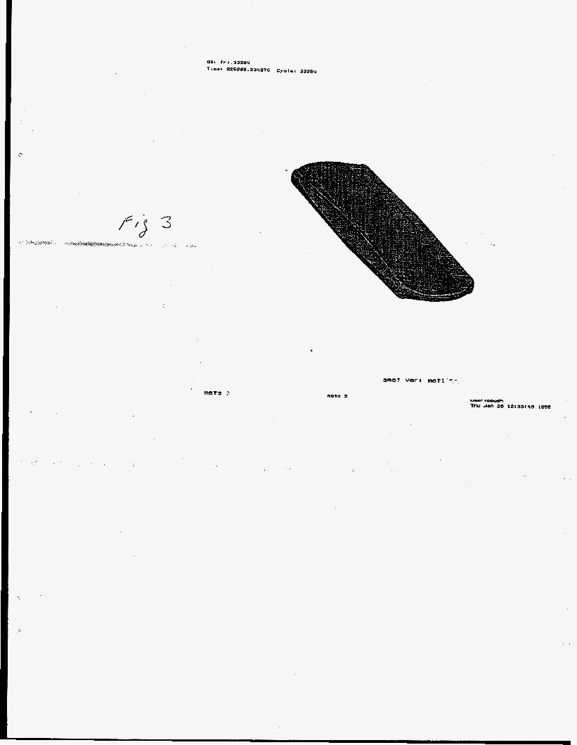
Figure 2 shows the evolution of the mesh and workpiece with time. The mesh shown above was used for illustration purposes. A more finely resolved mesh produced a part with the shape shown in Figure 3. Contours of the actual part exist at the mid plane reflection surface, at the location of the original edge of the cylindrical workpiece and in the plan view. The comparison between calculation and data in the plan view is shown in Figure 4. A friction coefficient of .3 was used with a limiting frictional stress of 15 Mp. These are reasonable values for these parameters, but they were chosen to provide the best fit to the data. The coulomb model applied here is too simplistic to expect any better agreement than that obtained. The intention here was merely to demongrate that with reasonable material and friction descriptions the ALE approach could provide quality results in a complex 3D geometry.
Figure 3. A MI representation of the forged part as calculated by ALE3D.
Figure 4. A comparison between calculated and measured part dimensions in the plan view.
Example 2 - extrusion
The approach to extrusion modeling is similar to that employed in the forging simulation. The extrusion die and ram are treated as Lagrangian objects with slip surfaces providing the interaction with a relaxing mesh containing the work piece and the volume into which the extruded material may flow. This approach is illustrated in Figure 5 . This is an idealized die geometry. Constraints were applied to prevent large deformation at the die orifice. An actual die configuration would have been much more massive to inhibit those distortions. The extruded confguration is shown in Figure 6. The ALE approach can treat the flow with little difticulty, but yet to be determined is the accuracy with which an actual extrusion process can be modeled This process involves a highly mupled thermomechanical system. Predicting the exact die geometry with mechanical loading and thermal effects included is required in order to produce
4 \

measurables like ram force and material flow. Another issue to be resolved is finding an approach that will allow efficient analysis of material flow throughout the entire charge run.
Figure 5. A Y-shaped part is to be extruded. Within the die are a cylindrical aluminum billet and a ram to drive the material. The mesh beneath the die provides volume in to which the extruded material can flow.
Figure 6. The shape of the extruded part.
Example 3 - rolling
Figure 7 iUustrates the geometry and mesh utilized in modeling a rolling pass with a 30% reduction. The rollers were given an applied angular velocity and allowed to relax to an equilibrium stress state under that rotation. The ingot was then pushed into the rolls with a velocity approximately equal to the linear rolling speed- Frictional forces then grabbed the ingot and pulled it through the rolls. The deformations were such that the mesh could remain Lagrangian throughout the calculation. This particular simulation depends critically on the contact algorithms which control the gap opening and closing between ingot and roller, and on the friction model assumed. In practice the product would be sensitive to the dynamics of the roller assembly. It serves to illustrate the requirement for a general purpose tool to posses a robust Lagrangian formulation and a significant structural analysis capability.
5

Figure 7. The initial and final rolling configurations. The calculation was Lagrangian with contact and friction forces pulling the ingot through the rolls.
Issues Associated with the ALE Technique
Remeshing
The hypothesis being investigated assumes that ALE can be used in its most general form. Objects that suffer little deformation can be treated Lagrangian, with contact discontinuities on their surface, as appropriate. Regions or materials that undergo large deformations will be treated with a continuous remeshing approach.
Assuming that the stresses, any constitutive parameters, such as plastic strain, and the material- voidair interface can be moved through the mesh with sufficient accufacy, the calculation can proceed to completion with minimally distorted elements and with no further intervention required. A more traditional approach would involve a Lagrangian mesh with an appropriate number of isolated remeshing operations. Some advantages of the ALE approach are that the dynamic remapping may be more accurate in preserving gradients in the quantities being remapped, and minimizing element distortion increases accuracy and minimizes computations. In an explicit mode the ALE calculation should run with a larger time step; implicit calculations should attain acceptable solutions with fewer iterations. ALE also brings a certain robustness in that the imposed regularity of the mesh is less likely to allow a drift into unphysical con6gurations or to require user intervention. The disadvantages are that the ALE calculation may require a larger total number of elements, and increased memory and logic are required to treat the inter- element flows and the multi-material elements that are generated. There may also be situations where a predetermined mesh may not be adequate and a remapping to an altered mesh is required- Experience thus far indicates that for many practical metal forming scenarios the predefined mesh is adequate. Remeshing is most likely to be required if one is modeling a forming process with multiple steps having different geometries.
Time Integration
Time scales for most metal forming problenis are too long for efficient time integration by means of a standard explicit scheme time step limited by the Courant stability condition. An implicit approach or a technique which artificially forces an explicit code to run at a larger time step is required Any conclusions reached about the utility of the ALE approach are independent of the time integration method ALE codes are generally built on a combination of a Lagrangian step followed by a remap operation. The two need not run at the same time step. The size of the advection time step is determined by accuracy considerations which limit the amount of flux that can pass through an element interface in one integration period. The number of advection steps required is therefore a function of the strain history of the working material, and is independent of the actual time scale of the process being modeled. The plan
6 1

is for ALE3D to have both implicit and explicit options available so that the user can choose the method most appropriate for the given application.
Contact Algorithms and Slide Surfaces
The interaction between the working material and whatever structure is involved should not be constrained by the geometric complexity of the structural surfaces. The precise dynamic path that the material will take cannot always be anticipated. The contact algorithm should be general enough that the specification of allowed contact surfaces can be consistent with the physically allowed degrees of freedom of the system being modeled. In the Lagrangian mode, the extreme, but not unreasonable, case, would allow any node on the surface of the working material to have the potential for coming in contact with any node on the surface of the containing structure. The contact logic can become quite expensive in this situation. Operating in the ALE mode, with a pre-positioned mesh, the association of fluid nodes with structural nodes is determined at problem generation time. This association or ordering of the nodes can change with time due to relative motion along the slide surface, but the reordering is straightforward because a node will always move from one element to an adjacent element. In this mode, the contact of one surface with another becomes a problem of material advection and the tracking of the material interfm as it moves from element to element.
occur in forging and casting scenarios. While closing of a material on a surface can be treated by traditional flow and interface tracking methods, the process is not automatically reversible when the material wants to separate from the wall. The technique can accommodate a switch to the Lagrangian mode either locally or globally, but this is not always an appropriate response. Contraction of a quiescent fluid on solidification, as arises in casting simulations, is one example of where that would be a reasonable approach. The more general response would be to allow a void to open by injecting a void-like material into the element to represent the gap that would exist between surfaces. The decision to open a void could be accurately made in the Lagrangian phase of the ALE time step. The node could then be placed back on the master surface creating a net volume flux into the element which would represent the injection ofvoid. This is the approach that will be followed in ALE3D. The accuracy of such an approach needs to be demonstrated
A more diEcult problem arises if the situation calls for a void to open at an interface. This can
Surface Interactions
The principal surface interaction of interest is friction. There does not appear to be any fundamental limitation to the ALE method as applied to physically based friction models. The ALE format is complicates the tracking of history variables, for example, but this is no different in scope than the difficulties encountered in tracking material properties through a relaxing mesh More complicated interactions such as crack formation are difficult to treat in any format. Certain failure models which generate strongly peaked damage functions are not readily made consistent with the continual remap approach.
Heat Conduction
For processes such as forging and extrusion where heat transport is either near steady state or is dominated by conduction within a material or at contact discontinuities, the various approaches are essentially identical. Operator splitting can be used in the heat transfer modeling. In this case the code
7

need not know the difference between an ALE mesh and a Lagrangian mesh. Casting simulation, however, may be an instance where the ALE approach may provide interesting alternative approaches. Certainly, during the die filling process, the use of a pre-positioned mesh through which the fluid is transported simplifies the treatment of the complicated flow. A similar simplification could extend to heat conduction. Thermal contact algorithms may be simplified and the problem of transport across an airhoid region could have a straightforward solution. More experience is required with thermomechanical simulations to understand the advantages and disadvantages of the ALE approach. Currently, there appears to be no fundamental flaw in the approach, and there could be significant simplifications which emerge.
Material Descriptions
The ALE approach is quite capable of dealing with typical models where flow stress is a function of temperature, strain rate and history variables such as accumulated strain. Also, there is nothing that would preclude treatment of anisotropic materials. In general, material models can be more dif€iculr to implement in an ALE code. Not all types of constitutive parameters are consistent with the continual remapping approach. It may be necessary, at times, to tailor the material model to the type of code structure in which it resides.
CONCLUSIONS
The ALE technique provides a robust method of dealing with both large and small defomntion flows and fluid-structure interactions. As such, it has the potential to be quite usefid in modeling metal forming processes. The ultimate utility of the approach will depend on the details of its implementation. The progress made thus far indicates that the emergence of a general purpose forming simulation tool from this approach is likely.
ACKNOWLEDGMENTS
The staff of Alma's Advanced Technology Center have been helpful in guiding this work. R. Becker has been particularly helpful in providing simulation data and interpretation. Work performed under the auspices of the U.S. Department of Energy by the Lawrence Livermore National Laboratory under contract No. W-7405-ENG-48.
mFERENCES
Hallquist, J. O., 1982, Theoretical Manualfor DYNWD, Lawrence Livermore National Laboratory,
Sharp, R., Anderson, S., Dube, E., Otero, I., Futral, S. 1994, UsersManual forALE3D, Lawrence
Smelser, R.E., Pishko, R, Klingensmith, M.A., 1991, Three Dimensional Forging Experiments - Case
Tipton, RE., 1992, private communication, Lawrence Livermore National Laboratory, Livermore, CA.
Livermore, CA, UCID-19401 draft.
Livermore National Laboratory, Livermore, CA, unpublished.
Studies, Alcoa Technical Center, Alcoa Center, PA, unpublished.
8


illustration of the evolution of the mesh and workpiece through time. The die is not shown and the &/void region is opaque so the workpiece can only be seen where it contacts the mesh surface.
m a t vart mtl'-.-

Y-Axis - cm I
N w 0 0 0 --L i, r;, A
0 0 0 t o
1 A
0
0 3
01
A
0

mesh var: m e s h 1 s m a t var: m a t 1
uaer goouch Thu Jan 25 12:95:56 1995

amat vera aatl . , - .
J

m e s h var: meshl-.-

088 I lr.BP921 Tsnrs 1388818.268888 Cyelr. 83021
m e s h varz m e s h 1