Embed Size (px)
Citation preview

CASE STUDY: SR 228 OVER
BREAKNECK CREEK
MODELING FOR STRUCTURES
DAVID MIRAGLIA, P.E. ROBERT GUYER, E.I.T.
NTM ENGINEERING, INC.

1. Project Introduction 2. Project Evolution & Alternates 3. Constructability & Design-ability 4. Identified Removal Limits 5. Identified Construction Sequence 6. Complex Reinforcement Layout 7. Detailing Examples
2
CASE STUDY AGENDA

Topic 1
3
PROJECT INTRODUCTION
MODELING FOR STRUCTURES

SR 228 Corridor Improvement PennDOT District 10-0 Adams Township in Butler County Project to widen corridor Replace structurally deficient bridge
over CSX Railroad Extend existing concrete arch under
approach to bridge 4
PROJECT INTRODUCTION

Arch is to the lef t s ide of the sur vey. Br idge is to the r ight s ide of the sur vey. S tat ion ahead to the r ight . Breakneck Creek f lows general ly nor th . Ent i re arch extens ion and hal f o f br idge constructed in Phase 1 .
5
PROJECT INTRODUCTION
Existing survEy
STA. AHD.
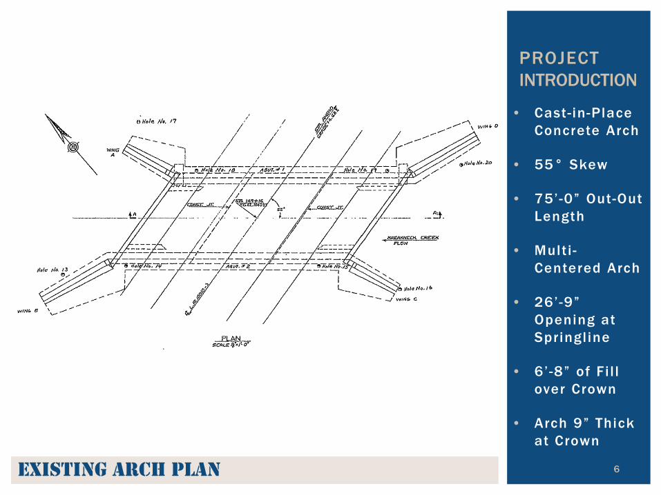
• Cast- in-Place Concrete Arch
• 55° Skew
• 75’-0” Out-Out Length
• Multi -Centered Arch
• 26’-9” Opening at Springl ine
• 6’-8” of Fi l l over Crown
• Arch 9” Thick at Crown
6
PROJECT INTRODUCTION
Existing arch Plan

7
PROJECT INTRODUCTION
Existing arch sEction
• Cast- in-Place Concrete Arch
• 55° Skew
• 75’-0” Out-Out Length
• Multi -Centered Arch
• 26’-9” Opening at Springl ine
• 6’-8” of Fi l l over Crown
• Arch 9” Thick at Crown

Topic 2
8
PROJECT EVOLUTION & ALTERNATES
MODELING FOR STRUCTURES

Extension in Kind Cast-in-Place Match Opening 75’-0” Upstream Friction Loss Doubles
9
PROJECT EVOLUTION
Increases Water Surface Elevation

The original extension-in-kind concept causes increases to the 100-year flood water sur face elevation upstream. No water sur face increases were tolerable. To reduce the fr ict ion loss, arch opening had to be increased.
10
PROJECT EVOLUTION
ExtEnsion in kind

11
Extension in Kind
All Precast Arch Culvert
Combination of Precast & Cast- in-Place
All Cast- in-Place Arch
ALTERNATES
A
PROS: Faster Construction Familiar Method Potential Cost Saver CONS: Skews are Limited Transition to Existing Without Good Tie-In, Must Replace Entire Arch

12
Extension in Kind
All Precast Arch Culvert
Combination of Precast & Cast- in-Place
All Cast- in-Place Arch
ALTERNATES
A
PROS: Precast Part Built Quickly C.I.P. Transition to Existing Fewer Skew Limitations CONS: Transition End Shapes Set Potential Debris Catcher Two Construction Methods More Costly
13
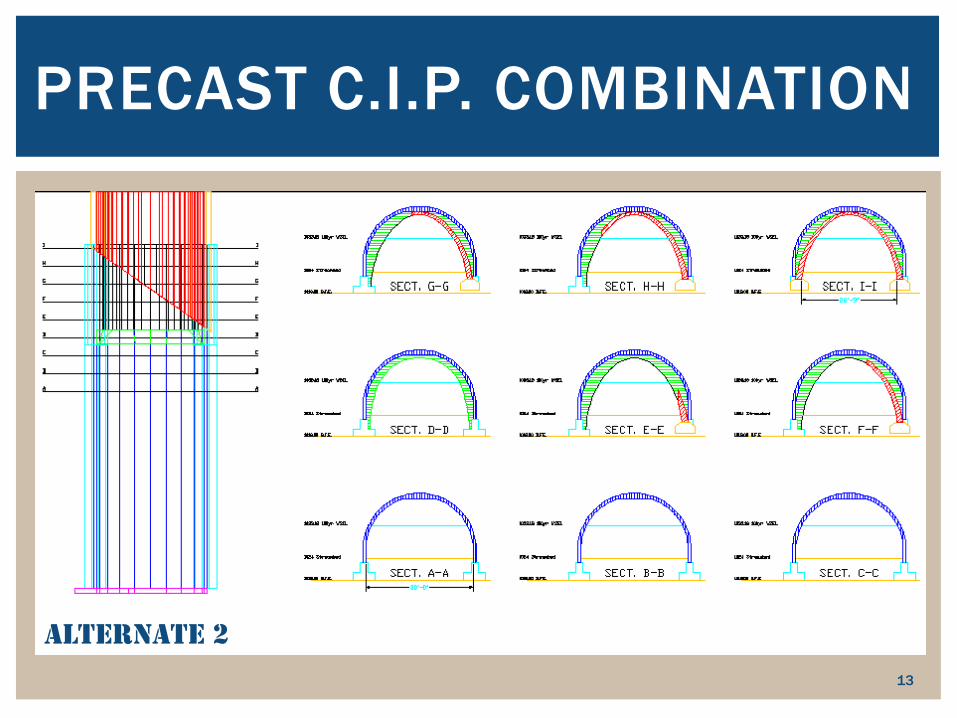
PRECAST C.I.P. COMBINATION
altErnatE 2

Star t w i th ex ist ing arch end. Remove ex is t ing spandrel wal l . Cast foot ings and pedesta ls . Cast “overarch” to square end. Tapered sect ion to t rans i t ion between openings. Cover ent i re length wi th 30’ precast arches . Add spandre l wal l .
14
ALTERNATE 2 Shor tcomings : Excavate to expose top of arch. Remove ex is t ing spandrel & counter for ts . Long st retch of cost ly precast . Tapered sect ion and overarch d i f f icult to cast . Tapered sect ion does not fu l ly remove b lunt end.

15
Star t w i th ex ist ing arch end. Remove ex is t ing spandrel wal l . Cast foot ings and pedesta ls . Cast “overarch” to square end. Tapered sect ion to t rans i t ion between openings. Ex tend length wi th 30’ precast arches . Add spandre l wal l .
ALTERNATE 3 Shor tcomings : Excavate to expose top of arch. Remove ex is t ing spandrel & counter for ts . Shor t s t retch of cost ly precast . Tapered sect ion and overarch d i f f icult to cast . B lunt end removed by even more complex cast ings .

16
DESIGN CHANGE!

17
Star t w i th ex ist ing arch end. Remove ex is t ing spandrel wal l . Cast foot ings . Cast “overarch” to square end. Tapered sect ion to t rans i t ion between openings. Ex tend length wi th 36’ precast arches . Add spandre l wal l .
ALTERNATE 4 Shor tcomings : Excavate to expose top of arch. Remove ex is t ing spandrel & counter for ts . Shor t s t retch of cost ly precast . Tapered sect ion and overarch d i f f icult to cast . Tapered sect ion does not fu l ly remove b lunt end.

18
Star t w i th ex ist ing arch end. Remove ex is t ing spandrel wal l . Cast foot ings and pedesta ls . Cast “overarch” to square end. Tapered sect ion to t rans i t ion between openings. Ex tend length wi th 36’ precast arches . Add spandre l wal l .
ALTERNATE 5 Shor tcomings : Excavate to expose top of arch. Remove ex is t ing spandrel & counter for ts . Shor t s t retch of cost ly precast . Tapered sect ion and overarch d i f f icult to cast . B lunt end removed by even more complex cast ings .

19
DESIGN CHANGE!
20
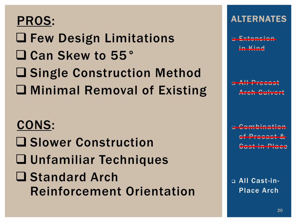
Extension in Kind
All Precast Arch Culvert
Combination of Precast & Cast- in-Place
All Cast- in-Place Arch
ALTERNATES
A
PROS: Few Design Limitations Can Skew to 55° Single Construction Method Minimal Removal of Existing CONS: Slower Construction Unfamiliar Techniques Standard Arch
Reinforcement Orientation

21
Star t w i th ex ist ing arch end. Use ex is t ing spandrel wal l as shor ing. Cast foot ings . Cast wedge arch to square end. Tapered sect ion to t rans i t ion between openings. Ex tend length wi th 36’ C . I .P. arch. Add spandre l wal l .
ALTERNATE 6 Shor tcomings : Wedge arch and tapered sect ion d i f f icult to cast . Each bar in wedge arch would be a d i f ferent length . Min imum f i l l over arch’s near r ight corner requi res more ROW, c reates unbalanced loading, and i t i s ug ly.

22
Use ex is t ing spandrel wal l as shor ing. Remove o ld wings & foot ings . Cast foot ings . Cast co l lar and tapered arch, w i th skewed end. Ex tend length wi th 36’ C . I .P arch wi th skewed ends . Add counter for ts & spandrel wal l . Add wingwal ls .
SELECTED ALTERNATIVE Advantages : S ingle method of construct ion. A large c rane is not requi red. End of arch matches roadway skew. Trans i t ion geometr y s impli f ied by bas ing proposed arch sect ion on ex ist ing arch sect ion. Water eased through taper.

23
SELECTED ALTERNATIVE Advantages : S ingle method of construct ion. A large c rane is not requi red. End of arch matches roadway skew. Trans i t ion geometr y s impli f ied by bas ing proposed arch sect ion on ex ist ing arch sect ion. Water eased through taper.
Arch or Barrel
Spandrel Wall or
Headwall
Wingwall
Footing
Counterfort
arch tErMs 101
Topic 3
24
CONSTRUCTABILITY & DESIGN-ABILITY
MODELING FOR STRUCTURES
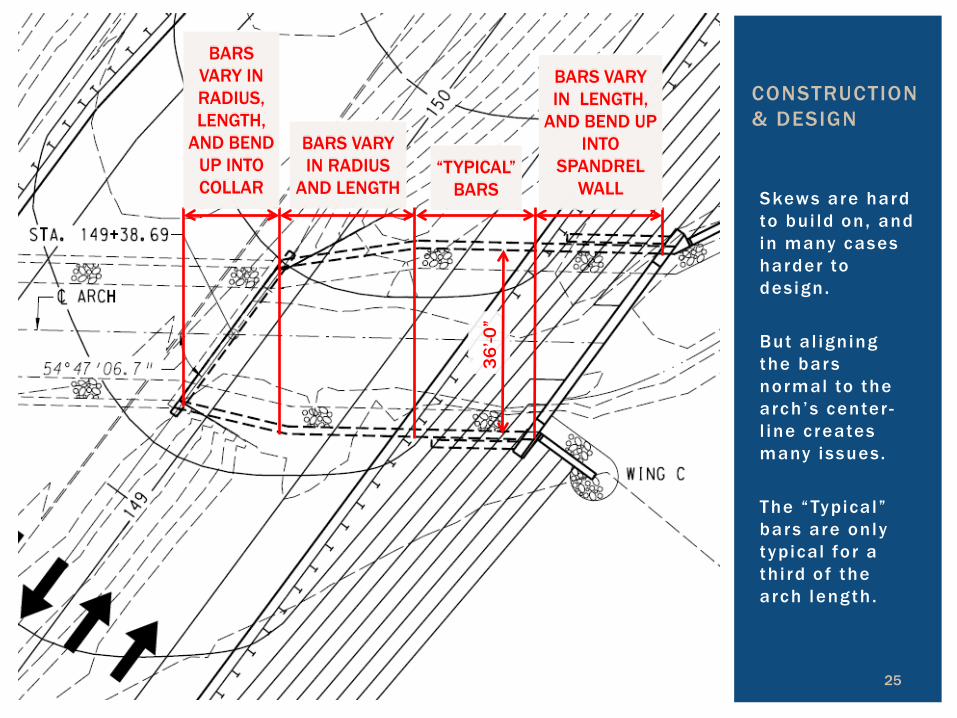
Skews are hard to bui ld on, and in many cases harder to des ign. But a l igning the bars normal to the arch’s center -l ine c reates many issues. The “Typica l” bars are only typical for a th i rd of the arch length .
25
CONSTRUCTION & DESIGN
BARS VARY IN RADIUS, LENGTH,
AND BEND UP INTO COLLAR
BARS VARY IN RADIUS
AND LENGTH “TYPICAL”
BARS
BARS VARY IN LENGTH,
AND BEND UP INTO
SPANDREL WALL
36’-0
”
BARS VARY IN RADIUS, LENGTH,
AND BEND UP INTO COLLAR
BARS VARY IN RADIUS
AND LENGTH “TYPICAL”
BARS
BARS VARY IN LENGTH,
AND BEND UP INTO
SPANDREL WALL
26
CONSTRUCTION & DESIGN
BARS VARY IN RADIUS
AND LENGTH
TYPICAL BARS
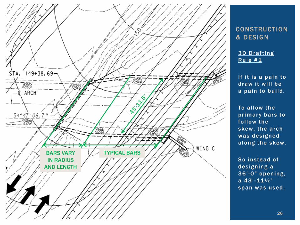
3D Draf t ing Rule #1 I f i t i s a pain to draw i t w i l l be a pain to bui ld . To a l low the pr imar y bars to fo l low the skew, the arch was des igned a long the skew. So instead of des igning a 36’ -0” opening, a 43 ’ -11½” span was used.
BARS VARY IN RADIUS
AND LENGTH
TYPICAL BARS

Topic 4
27
IDENTIFIED LIMITS OF REMOVAL
MODELING FOR STRUCTURES

Construct Temporary Shoring
Construct Cof ferdam
Excavate & Expose Wings
Remove Wings & Footings
Construct Proposed Footings
28
LIMITS OF REMOVAL

Topic 5
29
IDENTIFIED SEQUENCE OF
CONSTRUCTION
MODELING FOR STRUCTURES

Arch foot ings bui l t f i r s t . Segment C was bui l t next so construct ion could move in both d i rect ions . Segment B and the Spandrel Wal l could now be formed and poured against Segment C . Segment A was cast af ter so formwork could br idge between ex ist ing arch and hardened Segment B .
30
IDENTIFY SEQUENCE OF CONSTRUCTION
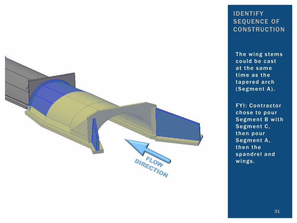
The wing stems could be cast at the same t ime as the tapered arch (Segment A) . FY I : Cont ractor chose to pour Segment B wi th Segment C , then pour Segment A , then the spandrel and wings .
31
IDENTIFY SEQUENCE OF CONSTRUCTION
32
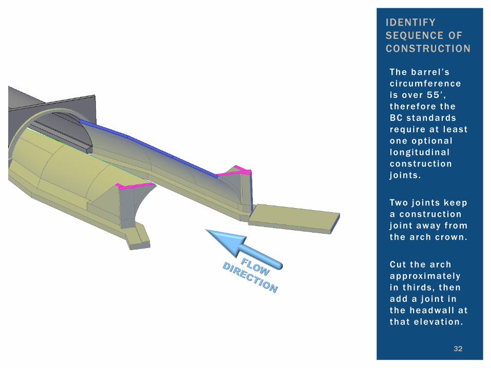
IDENTIFY SEQUENCE OF CONSTRUCTION
The bar re l ’s c i rcumference is over 55 ’ , therefore the BC standards requi re at least one opt ional longi tudinal construct ion jo ints . Two jo ints keep a construct ion jo int away f rom the arch c rown. Cut the arch approx imately in th i rds , then add a jo int in the headwal l at that e levat ion.
Topic 6
33
SIMPLIFY LAYOUT OF THE COMPLEX REINFORCEMENT
MODELING FOR STRUCTURES
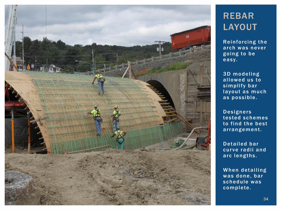
Reinforc ing the arch was never go ing to be easy. 3D model ing a l lowed us to s impli fy bar layout as much as poss ible . Des igners tested schemes to f ind the best ar rangement . Deta i led bar cur ve rad i i and arc lengths . When deta i l ing was done, bar schedule was complete .
34
REBAR LAYOUT

35
Typica l rebar in constant arch . Lower arch bars at 6” spac ing are lapped to the foot ing bars and extend past the opt ional constr. jo int . Upper arch bars at 12” spacing lap to lower bars . Upper arch bars osc i l late s ide - to -s ide to provide s tagger between sp l ices .
REBAR LAYOUT
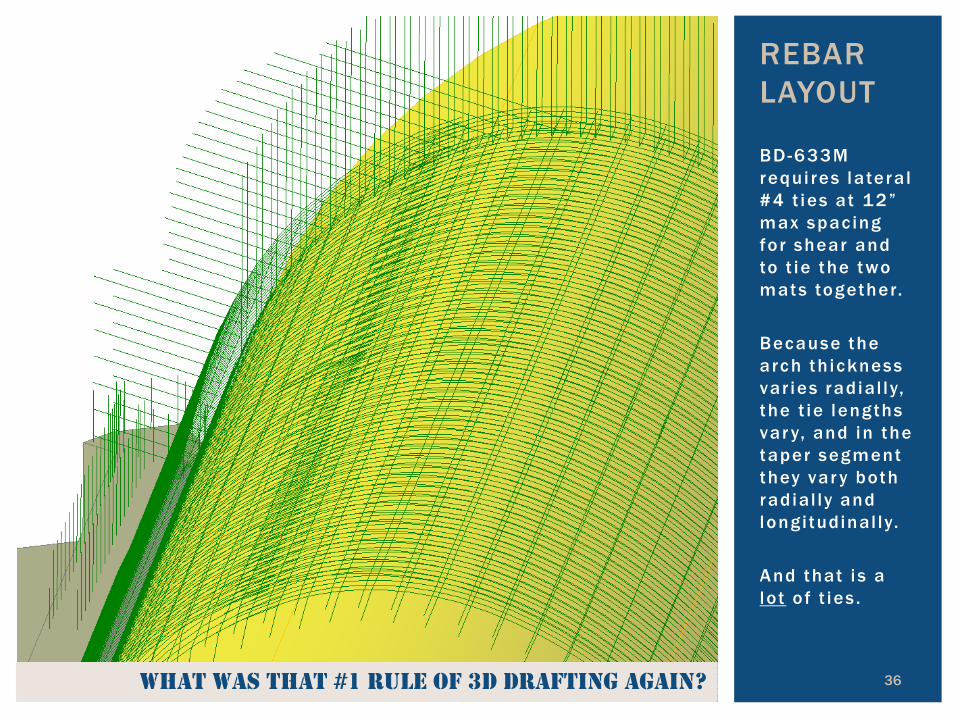
BD-633M requi res latera l #4 t ies at 12” max spac ing for shear and to t ie the two mats together. Because the arch th ickness var ies rad ial ly, the t ie lengths var y, and in the taper segment they var y both rad ial ly and longi tudinal ly. And that i s a lot o f t ies .
36
REBAR LAYOUT
latEral shEar tiEs not shoWn For clarity …and BEcausE that’s an aWFul lot oF tiEs to draW… What Was that #1 rulE oF 3d draFting again?

37
REBAR LAYOUT
Opt ion A : Provide a deta i led shear t ie matr ix that would show bar marks as they var y rad ia l ly & longi tudinal ly. Opt ion B : Use #3 t ies at 6” rad ial ly, pre -bent w i th a J -hook on one end, and f ie ld bent to 90° at the other. We chose B… Cont ractor went w i th A .
9576 tiEs in 4 diFFErEnt lEngths
38
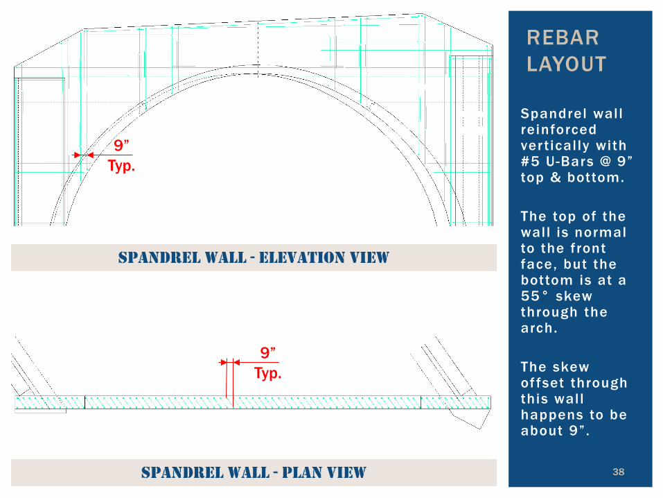
Spandrel wall reinforced ver t ical ly with #5 U-Bars @ 9” top & bottom. The top of the wall is normal to the front face, but the bottom is at a 55° skew through the arch. The skew of fset through this wall happens to be about 9”.
REBAR LAYOUT
sPandrEl Wall - Plan viEW
sPandrEl Wall - ElEvation viEW
9” Typ.
9” Typ.

sPandrEl Wall - Plan viEW
sPandrEl Wall - ElEvation viEW
9” Typ.
9” Typ.
39
The top U-bars could have been normal to the top of the wal l , the bottom U-bars skewed, and a spi ra l would have been created for the whole wal l . However, an ef fect ive way to present th is on 2D drawings wasn’t found. So a l l of the bars were skewed except four U-bars in the top corners.
Intrados Falsework
Concrete Arch
Spandrel Wall Reinforcement
REBAR LAYOUT

The photos used throughout the presentat ion were taken by : Tom Knier iem
D - 1 0 S t r uc t u ra l C o n t r o l E n g i n e e r
Joe Roman
K C I P r o j . M a n a g e r
John
Yamashita N T M E n g i n e e r
40
ADDITIONAL CONSTRUCTION PHOTOS

Topic 7
41
DETAILING EXAMPLES
MODELING FOR STRUCTURES
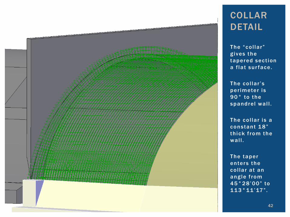
The “co l lar” g ives the tapered sect ion a f lat sur face. The co l lar ’s per imeter i s 90° to the spandrel wal l . The co l lar i s a constant 18” th ick f rom the wal l . The taper enters the co l lar at an ang le f rom 45°28’00” to 113°11’17” . 42
COLLAR DETAIL

Counter for ts suppor t the spandrel wal l against latera l ear th pressure. Smal l counter -for ts can be atop the arch, but wi l l create upl i f t on the arch. PennDOT’s ARCH sof tware cannot analyze these discreet loads.
43
COUNTERFORT PEDESTALS
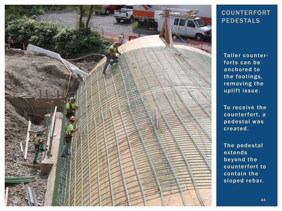
Tal ler counter -for ts can be anchored to the foot ings, removing the upl i f t issue. To receive the counter for t , a pedestal was created. The pedestal extends beyond the counter for t to contain the s loped rebar.
44
COUNTERFORT PEDESTALS

Counter for t ends at wal l , c reat ing an acute corner which is hard to form & easy to spal l . Reinforcement ex tends above and beyond headwal l . Could square the top, but i ssue re locates to the bot tom. A lso , the counter for t ’s top and s ides are no longer at 90°.
45
COUNTERFORT CONNECTION TO SPANDREL

46
Top of counter for t c l ipped to e l iminate form & spal l issue. Reinforcement bent to enter the headwal l hor izontal ly. Front of headwal l bumped out to prov ide development length of counter for t hooks.
COUNTERFORT CONNECTION TO SPANDREL
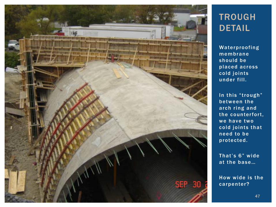
Waterproofing membrane should be p laced across co ld jo ints under f i l l . In th is “ t rough” between the arch r ing and the counter for t , we have two co ld jo ints that need to be protected. That ’s 6” w ide at the base… How wide is the carpenter?
47
TROUGH DETAIL
Waterproofing Membrane
48
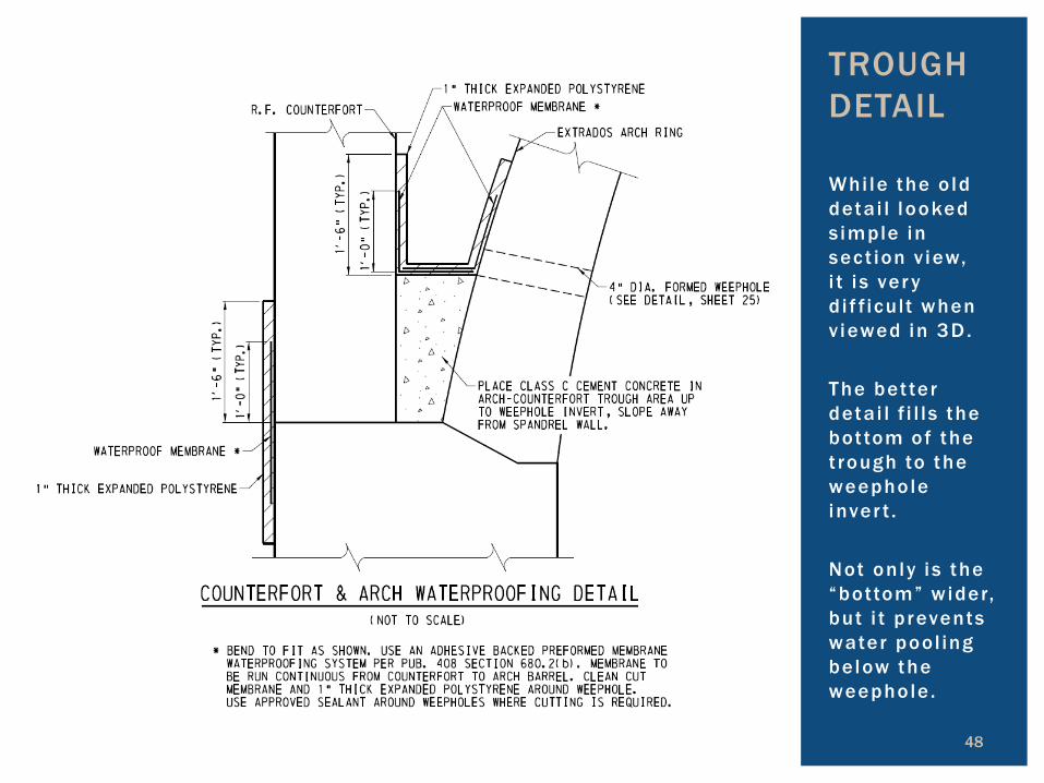
Whi le the o ld deta i l looked s imple in sect ion v iew, i t i s ver y d i f f icult when v iewed in 3D. The bet ter deta i l f i l ls the bot tom of the t rough to the weephole inver t . Not only i s the “bottom” wider, but i t prevents water pool ing below the weephole .
TROUGH DETAIL

49
The 3D l imits of backfi l l can be used to locate the requi red l imits of the spandrel wal l . C l ipping the corners reduces excess wal l , prevents the eros ion concerns of the future inspectors, and is better aesthet ical ly.
Theoretical Toe of Slope
Practical Toe of Slope
SPANDREL WALL CLIPS
sPandrEl Wall – FroM aBovE thE roadWay
Spandrel Wall

50
The 3D l imits of backfi l l can be used to locate the requi red l imits of the spandrel wal l . C l ipping the corners reduces excess wal l , prevents the eros ion concerns of the inspectors in the future , and is better aesthet ical ly.
SPANDREL WALL CLIPS
sPandrEl Wall – FroM strEaM lEvEl
Almost Done… CONCLUSION
MODELING FOR STRUCTURES
Where’s lunch?
51

1. Introduction to Project 2. Alternate Study 3. Constructability & Design-ability 4. Limits of Removal 5. Sequence of Construction 6. Layout of Reinforcement 7. Examples of Detailing
52
CASE STUDY SUMMARY