Embed Size (px)
Citation preview

111
3D printed fluidics with embedded analytic functionality forautomated reaction optimisationAndrew J. Capel1, Andrew Wright1, Matthew J. Harding1, George W. Weaver1, Yuqi Li1,Russell A. Harris2, Steve Edmondson3, Ruth D. Goodridge4 and Steven D. R. Christie*1
Full Research Paper Open Access
Address:1Department of Chemistry, Loughborough University, Loughborough,LE11 3TU, UK, 2School of Mechanical Engineering, University ofLeeds, Leeds, LS2 9JT, UK, 3School of Materials, The University ofManchester, Manchester, M13 9PL, UK and 4Faculty of Engineering,The University of Nottingham, Nottingham, NG7 2RD, UK
Email:Steven D. R. Christie* - [email protected]
* Corresponding author
Keywords:3D printing; inline reaction analysis; reaction optimisation; selectivelaser melting; stereolithography
Beilstein J. Org. Chem. 2017, 13, 111–119.doi:10.3762/bjoc.13.14
Received: 19 October 2016Accepted: 29 December 2016Published: 18 January 2017
This article is part of the Thematic Series "Automated chemicalsynthesis".
Guest Editor: I. R. Baxendale
© 2017 Capel et al.; licensee Beilstein-Institut.License and terms: see end of document.
AbstractAdditive manufacturing or ‘3D printing’ is being developed as a novel manufacturing process for the production of bespoke micro-
and milliscale fluidic devices. When coupled with online monitoring and optimisation software, this offers an advanced, customised
method for performing automated chemical synthesis. This paper reports the use of two additive manufacturing processes, stereo-
lithography and selective laser melting, to create multifunctional fluidic devices with embedded reaction monitoring capability. The
selectively laser melted parts are the first published examples of multifunctional 3D printed metal fluidic devices. These devices
allow high temperature and pressure chemistry to be performed in solvent systems destructive to the majority of devices manufac-
tured via stereolithography, polymer jetting and fused deposition modelling processes previously utilised for this application. These
devices were integrated with commercially available flow chemistry, chromatographic and spectroscopic analysis equipment,
allowing automated online and inline optimisation of the reaction medium. This set-up allowed the optimisation of two reactions,
a ketone functional group interconversion and a fused polycyclic heterocycle formation, via spectroscopic and chromatographic
analysis.
111
IntroductionAdditive manufacturing (AM), or as it is widely known ‘3D
printing’, is the internationally recognised term used to describe
a wide range of manufacturing processes that can generate com-
plex three-dimensional parts, often with geometries which
would be extremely complex, or in some cases impossible to
manufacture using more conventional subtractive manufac-
turing processes [1]. In AM, parts are built layer-by-layer, using
processes such as material extrusion [2], material jetting [3], vat

Beilstein J. Org. Chem. 2017, 13, 111–119.
112
photopolymerisation [4], sheet lamination [5], powder bed
fusion [6], binder jetting and direct energy deposition [7,8]. AM
has gained widespread academic and industrial use for a diverse
set of applications ranging from biological to aeronautical
[9,10]. However, more recent research has demonstrated the
benefits of using 3D printing to produce microfluidic devices
using AM techniques such as stereolithography (SL) [11],
polymer jetting and fused deposition modelling (FDM) [12,13].
There is therefore considerable interest in the optimisation of
chemical systems using this type of multifunctional continuous
flow reactor. Notable recent work in this area has been carried
out by Cronin [14], Ley [15] and Jensen [16]. This research
highlights the array of benefits that manufacturing fluidic
devices via AM processes can bring, including the ability to
produce multimaterial parts with complex microscale features
and embedded functionality, allowing inline and online optimi-
sation of a reaction medium.
This paper presents a range of printed chemical reactors pro-
duced via the selective laser melting (SLM) and SL manufac-
turing processes. SLM is a powder-based additive manufac-
turing technique which uses a high-power energy source, typi-
cally a laser, to selectively melt a powder bed into a single solid
body [17]. SLM can manufacture parts in a range of chemically
inert and thermally stable metals such as stainless steel [18],
aluminium and titanium [19,20], and is therefore an attractive
technique for a number of industrial applications. SLM is
capable of producing parts at a layer thickness as low as 20 µm,
and with part geometries of +/− 0.1 mm being achieved over
smaller parts, however, even highly optimised SLM processes
can still experience problems with balling, thermal cracking,
unwanted surface roughness and difficulty with removing
un-melted powder from smaller cavities [6]. SL utilises layer-
by-layer photopolymerisation of a liquid resin bath to generate
fully dense polymer parts [21]. Typically these resins are com-
plex formulations based around a small selection of UV-curable
acrylates, epoxies and urethanes [4], whose poor mechanical
and chemical properties can limit the application of SL manu-
factured parts. However, well maintained machines are capable
of reproducibly producing parts at a layer thickness as low as
25 µm, making SL one of the most accurate and reproducible
AM processes [4]. Both SLM and SL are therefore attractive
manufacturing techniques for the production of milliscale
chemical reactors.
This research investigates how these two innovative processes
can be used to produce milliscale chemical reactors with in-
creased analytical functionality, by embedding spectroscopic
viewing windows across the reaction path length allowing inline
UV–vis spectroscopic analysis of the reaction medium. The
research also highlights the design freedom associated with
using AM processes, by designing custom reactor geometries
which allow these devices to be integrated with existing labora-
tory flow and analysis equipment [22].
Results and DiscussionPrevious work within this research group has demonstrated the
flexibility of AM for the production of milliscale chemical reac-
tors, with complex internal geometries as well as parts with em-
bedded spectroscopic capability [11,23]. In order to fully utilise
this flexibility, parts were designed which could be integrated
with existing flow and analytical instrumentation. An ideal
choice for this application is high-performance liquid chroma-
tography (HPLC). HPLC instrumentation is widely available in
most modern chemistry laboratories, and is ideally suited for
use in flow applications. Modern HPLC systems are typically
equipped with a binary or quaternary pumping system (flow
rates ≈0.01–10 mL/min), thermostatted heated compartments
(temperatures ≈20–100 °C), multiport sampling valves, as well
as separation, purification and UV–vis spectroscopic analysis
capability. The HPLC system, parts were also integrated with a
commercially available Uniqsis FlowSyn module providing
pumping and heating apparatus, allowing inline spectroscopic
reaction analysis via a portable UV–vis light source and
detector. This type of spectroscopy is often used for inline reac-
tion analysis due to its rapid data generation, however, it can
often be difficult to interpret for complex multifunctional
systems. On the other hand, chromatographic analysis methods
produce much more concise spectra allowing quantitative data
to be extrapolated, however, they often suffer from lengthy
method times significantly decreasing the reaction throughput
[24,25].
The HPLC equipment set-up, which varied between experi-
ments, was based around a four module Agilent 1100 series,
with two binary pumping modules, a thermostatted column
compartment module, a variable wavelength diode array
detector (DAD) compartment with a standard flow cell, as well
as an external six-port sampling valve. Using this set-up
allowed the flow medium to be pumped through a temperature
controlled reactor, which using a sampling valve would allow
the reaction medium to either be collected, injected onto the
HPLC column for separation or passed directly through a diode
array detector. The column would be flushed with the mobile
phase by the secondary pump, whilst being independently
heated by the same thermostatted compartment. By integrating
this system with 3D printed fluidic devices, it would be possible
to perform automated inline and online analysis of the reaction
media, affording substantial control over reaction residence
time, temperature, and reagent composition. However, in order
to achieve this level of control it was necessary to design
custom software: a series of intuitive ‘macro’ programs, which
Beilstein J. Org. Chem. 2017, 13, 111–119.
113
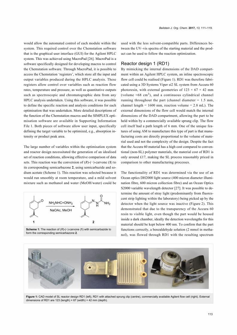
Figure 1: CAD model of SL reactor design RD1 (left), RD1 with attached sprung clip (centre), commercially available Agilent flow cell (right). Externaldimensions of RD1 are 123 (length) × 67 (width) × 42 mm (depth).
Scheme 1: The reaction of (R)-(−)-carvone (1) with semicarbazide toform the corresponding semicarbazone 2.
would allow the automated control of each module within the
system. This required control over the Chemstation software
that is the graphical user interface (GUI) for the Agilent HPLC
system. This was achieved using MacroPad [26]. MacroPad is a
software specifically designed for developing macros to control
the Chemstation software. Through MacroPad, it is possible to
access the Chemstation ‘registers’, which store all the input and
output variables produced during the HPLC analysis. These
registers allow control over variables such as reaction flow
rates, temperature and pressure, as well as quantitative outputs
such as spectroscopic and chromatographic data from any
HPLC analysis undertaken. Using this software, it was possible
to define the specific reaction and analysis conditions for each
optimisation that was undertaken. More detailed descriptions of
the function of the Chemstation macros and the SIMPLEX opti-
misation software are available in Supporting Information
File 1. Both pieces of software allow user input, specifically
defining the target variable to be optimized, e.g., absorption in-
tensity or product peak area.
The large number of variables within the optimisation system
and reactor design necessitated the generation of an idealised
set of reaction conditions, allowing effective comparison of data
sets. This reaction was the conversion of (R)-(−)-carvone (1) to
its corresponding semicarbazone 2, using semicarbazide and so-
dium acetate (Scheme 1). This reaction was selected because it
would run smoothly at room temperature, and a mild solvent
mixture such as methanol and water (MeOH/water) could be
used with the less solvent-compatible parts. Differences be-
tween the UV–vis spectra of the starting material and the prod-
uct can be used to follow the reaction optimization.
Reactor design 1 (RD1)By mimicking the internal dimensions of the DAD compart-
ment within an Agilent HPLC system, an inline spectroscopic
flow cell could be realised (Figure 1). RD1 was therefore fabri-
cated using a 3D Systems Viper si2 SL system from Accura 60
photoresin, with external geometries of 123 × 67 × 42 mm
(volume ≈68 cm3), and a continuous cylindrical channel
running throughout the part (channel diameter = 1.5 mm,
channel length = 1600 mm, reaction volume = 2.8 mL). The
external dimensions of the flow cell would match the internal
dimensions of the DAD compartment, allowing the part to be
held within by a commercially available sprung clip. The flow
cell itself had a path length of 6 mm. One of the unique fea-
tures of using AM to manufacture this type of part is that manu-
facturing costs are directly proportional to the volume of mate-
rial used and not the complexity of the design. Despite the fact
that the Accura 60 material has a high cost compared to conven-
tional (non-SL) polymer materials, the material cost of RD1 is
only around £17, making the SL process reasonably priced in
comparison to other manufacturing processes.
The functionality of RD1 was determined via the use of an
Ocean optics DH2000 light source (400 micron diameter illumi-
nation fibre, 600 micron collection fibre) and an Ocean Optics
S2000 variable wavelength detector [27]. It was possible to de-
termine the amount of stray light (predominantly from fluores-
cent strip lighting within the laboratory) being picked up by the
detector when the light source was inactive (Figure 2). This
demonstrated that due to the transparency of the Accura 60
resin to visible light, even though the part would be housed
inside a dark chamber, ideally the detection wavelengths for this
material should be kept below 400 nm. To confirm that the part
functions correctly, a benzaldehyde solution (2 mmol in metha-
nol), was flowed through RD1 with the resulting spectrum

Beilstein J. Org. Chem. 2017, 13, 111–119.
114
Figure 2: Energy versus wavelength spectra comparing the amount of stray light being picked up by the detector using both RD1 and a commercialflow cell (left), normalised absorption spectra of a benzaldehdye solution passing through both RD1 and a commercial flow cell (right).
Table 1: Conditions and limits for the optimisation used in tandem withRD1. Ketone 1 concentration 0.40 mmol/L, semicarbazide concentra-tion 1.20 mmol/L.
Optimisation variable Value
flow rate range 0.2–1 mL/mintemperature range 25–80 °CSIMPLEX temperature variation 5 °CSIMPLEX flow rate variation 0.1 mL/minmaximum data points 30
being compared to that achieved through the Ocean Optics flow
cell. Having normalised the data it was clear that the two spec-
tra were very similar above wavelengths of around 260 nm.
RD1 was therefore tested using the carvone functional group
interconversion previously outlined (Scheme 1) and would be
fully automated, using the spectroscopic data generated from
the inline flow cell as the controlling output that would run the
Chemstation control macros and optimisation software. The
software was set to optimise for maximum UV–vis absorbance
due to the semicarbazone by automatically varying both temper-
ature and flow rate. For this optimisation an Agilent 1100 series
binary pumping module was used to pump the two reagent
flows, which passed through a 5 mL stainless steel coil reactor.
This reactor was attached to a heating mandrel, and heated
using the temperature controlled heating module of a Uniqsis
FlowSyn. The flow would then pass into a six-port valve,
allowing it to be redirected into either a collection vial, or pass
through RD1 for spectroscopic data collection (Figure 3 and
Table 1).
The analysis macro used during this specific optimisation would
monitor the intensity of absorption at a single predetermined
Figure 3: Reactor set-up for carvone optimisation using RD1 as aninline spectroscopic flow cell. Reagents were pumped using an Agilent1100 series HPLC pumping module. A Uniqsis FlowSyn was used toheat and cool the 5 mL stainless steel coil reactor. The flow passedonto a stand-alone six-port valve, whereby samples were eitherpassed into a collection vial or passed through RD1 which sat withinthe DAD compartment of the same Agilent 1100 series HPLC.
wavelength (275 nm). At this wavelength the carvone starting
material has very low absorbance, whereas the semicarbazone
product has significant absorbance. The increase in intensity of
absorbance at this value could therefore be attributed to the
presence of an increased concentration of the reaction product.
Prior to each new set of experimental conditions, the flow cell
would be flushed with a MeOH/water mix (1:1 ratio), allowing
the detector to establish a new baseline. Figure 4 shows the
reactor held in place in the HPLC compartment.
Beilstein J. Org. Chem. 2017, 13, 111–119.
115
Figure 6: SLM reactor RD2 (left), CAD model of RD2 (right). External dimensions of RD2 are 100 (length) × 20 (width) × 20 mm (depth).
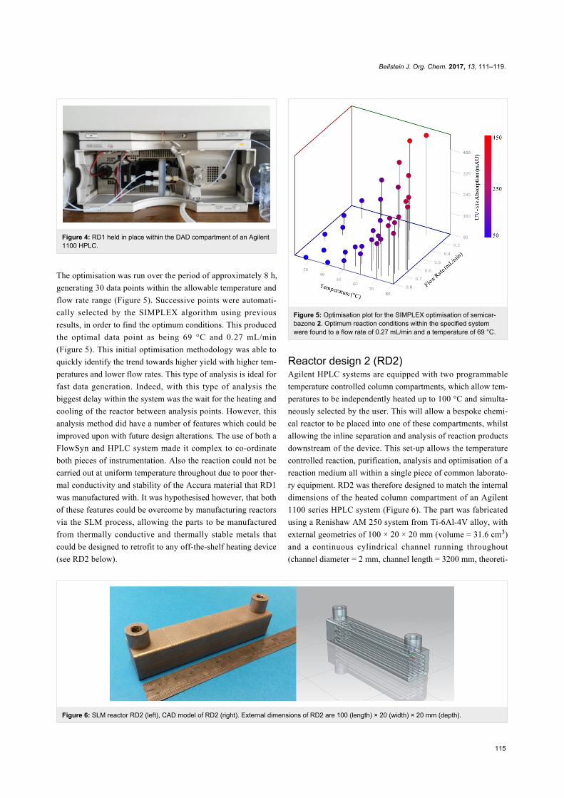
Figure 4: RD1 held in place within the DAD compartment of an Agilent1100 HPLC.
The optimisation was run over the period of approximately 8 h,
generating 30 data points within the allowable temperature and
flow rate range (Figure 5). Successive points were automati-
cally selected by the SIMPLEX algorithm using previous
results, in order to find the optimum conditions. This produced
the optimal data point as being 69 °C and 0.27 mL/min
(Figure 5). This initial optimisation methodology was able to
quickly identify the trend towards higher yield with higher tem-
peratures and lower flow rates. This type of analysis is ideal for
fast data generation. Indeed, with this type of analysis the
biggest delay within the system was the wait for the heating and
cooling of the reactor between analysis points. However, this
analysis method did have a number of features which could be
improved upon with future design alterations. The use of both a
FlowSyn and HPLC system made it complex to co-ordinate
both pieces of instrumentation. Also the reaction could not be
carried out at uniform temperature throughout due to poor ther-
mal conductivity and stability of the Accura material that RD1
was manufactured with. It was hypothesised however, that both
of these features could be overcome by manufacturing reactors
via the SLM process, allowing the parts to be manufactured
from thermally conductive and thermally stable metals that
could be designed to retrofit to any off-the-shelf heating device
(see RD2 below).
Figure 5: Optimisation plot for the SIMPLEX optimisation of semicar-bazone 2. Optimum reaction conditions within the specified systemwere found to a flow rate of 0.27 mL/min and a temperature of 69 °C.
Reactor design 2 (RD2)Agilent HPLC systems are equipped with two programmable
temperature controlled column compartments, which allow tem-
peratures to be independently heated up to 100 °C and simulta-
neously selected by the user. This will allow a bespoke chemi-
cal reactor to be placed into one of these compartments, whilst
allowing the inline separation and analysis of reaction products
downstream of the device. This set-up allows the temperature
controlled reaction, purification, analysis and optimisation of a
reaction medium all within a single piece of common laborato-
ry equipment. RD2 was therefore designed to match the internal
dimensions of the heated column compartment of an Agilent
1100 series HPLC system (Figure 6). The part was fabricated
using a Renishaw AM 250 system from Ti-6Al-4V alloy, with
external geometries of 100 × 20 × 20 mm (volume = 31.6 cm3)
and a continuous cylindrical channel running throughout
(channel diameter = 2 mm, channel length = 3200 mm, theoreti-

Beilstein J. Org. Chem. 2017, 13, 111–119.
116
Scheme 2: The reaction of pentafluoropyridine (3) with 2-(methylamino)phenol (4) to form the corresponding fused polycyclic heterocycle 5.
cal reaction volume = 10 mL). The titanium alloy used to manu-
facture the part is thermally stable across a substantial tempera-
ture range, and chemically compatible with a wide range of
organic solvents and reagents, making it ideally suited to con-
tinuous flow chemistry.
The part was again tested using the semicarbazide preparation
previously outlined (Scheme 1), and automated through the
Chemstation software. For this optimisation an 1100 series
binary pump module was used to pump the two reagent flows
directly through RD2. The part was placed into the HPLC
column compartment (Figure 7), and heated using the tempera-
ture control settings within the Chemstation software. The flow
would then pass into a six port sampling valve, allowing the
material to pass into either a collection vial, or be injected
directly onto the HPLC column for purification and further
analysis. To verify the actual temperature versus the set temper-
ature, we flowed a methanol/water mix through the set-up and
measured the temperature at the reactor exit. We did see an
offset of around 5 °C for every set increase of 20 °C. Whilst
there is predictability in this, this confirms that accurate reac-
tion temperature measurement would be desirable in future
design. For further details regarding the experimental set-up see
Supporting Information File 1.
Figure 7: RD2 held in place within the thermostatted Agilent 1100series column department.
The specific macro used during this optimisation was set up to
calculate the peak area for both the carvone starting material, as
well as the semicarbazone product. The percentage conversion
of the starting material was then outputted as a single value. The
optimisation was run over the period of around 24 hours, gener-
ating 40 data points within the allowable temperature and flow
rate range (Figure 8). This produced the optimal reaction condi-
tions as being 79.6 °C and 0.24 mL/min, which had a conver-
sion of 56%. Again the system was able to identify the general
trend towards higher yields at lower flow rates and higher tem-
peratures. However, switching from spectroscopic to chromato-
graphic analysis caused a significant increase in the amount of
time required to complete the optimisation, with each data point
taking around 35 minutes to generate. However, the system did
produce much more easily-quantifiable spectra resulting in a
significant improvement in the reliability and accuracy of the
data generated.
Figure 8: Optimisation plot for the SIMPLEX optimisation of semicar-bazone 1. Optimum reaction conditions were found to be a flow rate of0.24 mL/min and a temperature of 79.6 °C.
The thermal and chemical stability of the Ti-6Al-4V alloy used
to manufacture RD2 opened up a much wider range of poten-
tial chemical syntheses possible using this device. It was
hypothesised that integrating RD2 with a commercially avail-
able FlowSyn module would allow a much larger chemical
space to be analysed (<200 °C). The formation of a fused poly-
cyclic heterocycle 5 (Scheme 2), from pentafluoropyridine (3)
and 2-(methylamino)phenol (4), was chosen as this would

Beilstein J. Org. Chem. 2017, 13, 111–119.
117
Figure 10: SLM reactor design RD3 (left), CAD model of RD3 (right). External dimensions of RD3 are 89 (length) × 27 (width) × 38 mm (depth).
generate a more complex optimisation set with two starting ma-
terials, the reaction product as well as any potential reaction
intermediates and unwanted side products. The reaction would
also require elevated temperatures as well as a solvent system
which would have proved destructive to the Accura resin used
to manufacture RD1. These types of fused polycyclic hetero-
cycles are of significant interest, as they have been shown
to have significant antitrypanosomal activities against
Trypanosoma brucei rhodesiense, with low or no toxicity
towards mammalian cells [28], thus testing the system against a
real research problem.
The reaction set-up for this optimisation consisted of RD2 being
held into place on the chip heater of a FlowSyn system by a
metal clip. The system was allowed to reach temperature with
solvent pumping throughout the system, before switching to a
reagent flow. The product from each optimisation point was
collected and analysed via UV–vis spectroscopy at a wave-
length of 330 nm. For further details regarding the experimen-
tal set-up see Supporting Information File 1.
The optimisation generated two optimal data points at
0.24 mL/min and 156 °C, and 0.24 mL/min and 170 °C, respec-
tively (Figure 9). Despite a 12-fold increase in reaction conver-
sion over the course of the optimisation, the optimum data point
generated correlated to only around 23.4% conversion. This
output does perhaps suggest that at a lower flow rate, or higher
residence time, a more optimal set of reaction conditions could
be realised. Limitations of the current pumping system used
above made it impractical to drop to a lower flow rate, however,
the inherent benefit of AM processes is that a new reactor
design with a larger internal reaction volume can be realised
within a short time period. In this manner AM affords the op-
portunity to design and develop reactor geometries, specifically
tailored to the individual needs of the reaction in use, be that in
terms of reactor dimensions or specific analysis sites located
throughout the port, in a highly cost and time efficient manner.
If coupled with HPLC purification of target compounds, it
offers a rapid method for generation of quantitites of com-
pounds for further testing.
Figure 9: Optimisation plot for the SIMPLEX optimisation of the fusedpolycyclic heterocycle 5. Two optimal data points at 0.24 mL/min and156 °C, and 0.24 mL/min and 170 °C were found.
Reactor design 3 (RD3)Having previously demonstrated that it was possible to manu-
facture a flow cell with in-build windows from polymer via the
SL process (RD1), it was logical to produce a similar part from
metal. This would allow high and low-temperature reactions to
be undertaken, in a much larger range of chemical reagent and
solvents. RD3 was again produced using a Renishaw AM 250
system from Ti-6Al-4V alloy, with external geometries of
89 × 27 × 38 mm (volume = 24.6 cm3) and a continuous cylin-
drical channel running throughout (channel diameter = 2 mm,
channel length = 190 mm, reaction volume = 0.6 mL)
(Figure 10). Like RD1, the external dimensions of the flow cell
would match the internal dimensions of the DAD compartment,

Beilstein J. Org. Chem. 2017, 13, 111–119.
118
whereby a flow cell of path length 2 mm would sit approxi-
mately half way along the flow path . For further details
regarding the experimental set-up see Supporting Information
File 1.
Again the part was tested using the model semicarbazone reac-
tion and the same optimisation set-up used during the testing of
RD1. However, the 5 mL stainless steel reaction coil previ-
ously used was replaced by RD3, which sat in the temperature
controlled column compartment of the HPLC. This increased
the total internal reaction volume to around 10.3 mL. This set-
up meant that the entire reaction, analysis and optimisation
would be performed within a single HPLC system, using only
AM parts. The optimisation was run over the period of about
6 hours, generating 20 data points within the allowable tempera-
ture and flow rate range. This produced the optimal data point
as being 75 °C and 0.2 mL/min (Figure 11). Both RD2 and RD3
have demonstrated the immense potential of AM processes to
not only manufacture bespoke and customisable geometries
which can be integrated with existing laboratory equipment, but
also to manufacture functional chemical and thermally compati-
ble reactors with embedded functionality.
Figure 11: Optimisation plot for the SIMPLEX optimisation of semicar-bazone 2. Optimum reaction conditions were found to be a flow rate of0.2 mL/min and a temperature of 75 °C.
ConclusionAM has been shown to be a highly versatile manufacturing
process for the production of multifunctional bespoke flow
reactors. This allows conceptual parts to be realised within a
short time period, and consequently a rapid optimisation of the
designed geometry can be achieved. The customisable nature of
the AM process allowed the generation of a selection of custom
built metal and polymer parts. These parts were designed so that
they could be integrated with existing pieces of flow and analy-
sis instrumentation, as well as housing analytical functionality
in the form of spectroscopic windows. By integrating this type
of custom-made device with a piece of intuitive software, it was
possible to develop a fully automated flow system capable of
generating a significant amount of data at discrete locations
within the flow system. There is therefore significant future
research scope in this area where additive manufacturing offers
the ability to embed analytical technology in reactors in innova-
tive ways.
Supporting InformationSupporting Information File 1General considerations, macros and experimental data.
[http://www.beilstein-journals.org/bjoc/content/
supplementary/1860-5397-13-14-S1.pdf]
AcknowledgementsThanks to Mark East and Mark Hardy from the University of
Nottingham, for the manufacture of the SL parts, as well as
Renishaw for the manufacture of the SLM parts. Also thanks go
to Uniqsis Ltd for providing technical support within the
research. Finally thanks must go to our funders, Loughborough
University Materials Research School and EPSRC.
References1. Wong, K. V.; Hernandez, A. ISRN Mech. Eng. 2012, No. 208760.
doi:10.5402/2012/2087602. Masood, S. H. Rapid Prototyp. J. 1996, 2, 24–33.
doi:10.1108/135525496101090543. Shallan, A. I.; Smejkal, P.; Corban, M.; Guijt, R. M.; Breadmore, M. C.
Anal. Chem. 2014, 86, 3124–3130. doi:10.1021/ac40418574. Melchels, F. P. W.; Feijen, J.; Grijpma, D. W. Biomaterials 2010, 31,
6121–6130. doi:10.1016/j.biomaterials.2010.04.0505. Friel, R. J.; Harris, R. A. Procedia CIRP 2013, 6, 35–40.
doi:10.1016/j.procir.2013.03.0046. Kruth, J. P.; Froyen, L.; Van Vaerenbergh, J.; Mercelis, P.;
Rombouts, M.; Lauwers, B. J. Mater. Process. Technol. 2004, 149,616–622. doi:10.1016/j.jmatprotec.2003.11.051
7. Bai, Y.; Williams, C. B. Rapid Prototyp. J. 2015, 21, 177–185.doi:10.1108/RPJ-12-2014-0180
8. Carroll, B. E.; Palmer, T. A.; Beese, A. M. Acta Mater. 2015, 87,309–320. doi:10.1016/j.actamat.2014.12.054
9. Zein, I.; Hutmacher, D. W.; Tan, K. C.; Teoh, S. H. Biomaterials 2002,23, 1169–1185. doi:10.1016/S0142-9612(01)00232-0
10. Brandl, E.; Baufeld, B.; Leyens, C.; Gault, R. Phys. Procedia 2010, 5,595–606. doi:10.1016/j.phpro.2010.08.087
11. Monaghan, T.; Harding, M. J.; Harris, R. A.; Friel, R. J.;Christie, S. D. R. Lab Chip 2016, 16, 3362–3373.doi:10.1039/C6LC00562D

Beilstein J. Org. Chem. 2017, 13, 111–119.
119
12. Anderson, K. B.; Lockwood, S. Y.; Martin, R. S.; Spence, D. M.Anal. Chem. 2013, 85, 5622–5626. doi:10.1021/ac4009594
13. Capel, A. J.; Edmondson, S.; Christie, S. D. R.; Goodridge, R. D.;Bibb, R. J.; Thurstans, M. Lab Chip 2013, 13, 4583–4590.doi:10.1039/c3lc50844g
14. Tsuda, S.; Jaffery, H.; Doran, D.; Hezwani, M.; Robbins, P. J.;Yoshida, M.; Cronin, L. PLoS One 2015, 10, e0141640.doi:10.1371/journal.pone.0141640
15. Fitzpatrick, D. E.; Battilocchio, C.; Ley, S. V. Org. Process Res. Dev.2016, 20, 386–394. doi:10.1021/acs.oprd.5b00313
16. Moore, J. S.; Smith, C. D.; Jensen, K. F. React. Chem. Eng. 2016, 1,272–279. doi:10.1039/C6RE00007J
17. Yadroitsev, I.; Smurov, I. Phys. Procedia 2011, 12, 264–270.doi:10.1016/j.phpro.2011.03.034
18. Rombouts, M.; Kruth, J. P.; Froyen, L.; Mercelis, P. CIRP Ann. 2006,55, 187–192. doi:10.1016/S0007-8506(07)60395-3
19. Louvis, E.; Fox, P.; Sutcliffe, C. J. J. Mater. Process. Technol. 2011,211, 275–284. doi:10.1016/j.jmatprotec.2010.09.019
20. Thijs, L.; Verhaeghe, F.; Craeghs, T.; Van Humbeeck, J.; Kruth, J.-P.Acta Mater. 2010, 58, 3303–3312. doi:10.1016/j.actamat.2010.02.004
21. Sager, B.; Rosen, D. W.; Shilling, M.; Kurfess, T. R. ExperimentalStudies in Stereolithography Resolution. In Proceedings of the AnnualInternational Solid Freeform Fabrication Symposium, The FourteenthSolid Freeform Fabrication (SFF) Symposium, Austin, TX, Aug 4–6,2003; University of Texas at Austin: Austin, TX, 2003; pp 70–81.
22. Kitson, P. J.; Glatzel, S.; Chen, W.; Lin, C.-G.; Song, Y.-F.; Cronin, L.Nat. Protoc. 2016, 11, 920–936. doi:10.1038/nprot.2016.041
23. Monaghan, T.; Capel, A. J.; Christie, S. D.; Harris, R. A.; Friel, R. J.Composites, Part A 2015, 76, 181–193.doi:10.1016/j.compositesa.2015.05.032
24. Holmes, N.; Akien, G. R.; Savage, R. J. D.; Stanetty, C.;Baxendale, I. R.; Blacker, A. J.; Taylor, B. A.; Woodward, R. L.;Meadows, R. E.; Bourne, R. A. React. Chem. Eng. 2016, 1, 96–100.doi:10.1039/C5RE00083A
25. Sans, V.; Cronin, L. Chem. Soc. Rev. 2016, 45, 2032–2043.doi:10.1039/C5CS00793C
26. MacroPad. http://waleson.eu/products/macropad/ (accessed Jan 15,2015).
27. OceanOptics. http://www.oceanoptics.com/ (accessed Jan 15, 2015).28. Brown-Barber, C. J. Ph.D. Thesis, Georgia State University, Atlanta,
GA, USA, 2010.
License and TermsThis is an Open Access article under the terms of the
Creative Commons Attribution License
(http://creativecommons.org/licenses/by/4.0), which
permits unrestricted use, distribution, and reproduction in
any medium, provided the original work is properly cited.
The license is subject to the Beilstein Journal of Organic
Chemistry terms and conditions:
(http://www.beilstein-journals.org/bjoc)
The definitive version of this article is the electronic one
which can be found at:
doi:10.3762/bjoc.13.14

![PEP Web - The Analytic Third: Working with Intersubjective ... … · analytic third'. This third subjectivity, the intersubjective analytic third Green's [1975] 'analytic object'),](https://img.pdfslide.net/doc/110x75/6099619e2d4b51336024f694/pep-web-the-analytic-third-working-with-intersubjective-analytic-third.jpg)


![FLASH: Fast Bayesian Optimization for Data Analytic Pipelines · widely adopted machine learning toolboxes provide the functionality to run analytic pipelines. Scikit-learn [36] and](https://img.pdfslide.net/doc/110x75/5c8ef1ab09d3f25a6d8b7bbe/flash-fast-bayesian-optimization-for-data-analytic-pipelines-widely-adopted.jpg)