Embed Size (px)
Citation preview
Simulation and Analysis of
Unbonded Nonwoven Fibrous Structures
Behnam Pourdeyhimi ¹, Benoit Mazé ¹, Hooman Vahedi Tafreshi ¹ ¹North Carolina State University, Nonwovens Cooperative Research Center, Raleigh, North Carolina 27695-8301 USA Correspondence to: Behnam Pourdeyhimi, Ph. D. email: [email protected]___________________________________________________________ ABSTRACT In this work we report on our algorithm for generating 3-D virtual structures resembling un-bonded fibrous webs. The paper discusses short and infinitely long fibers, each emulating a category of nonwoven fibrous medium. The structure Solid Volume Fraction (SVF), being the most important characteristic of a fibrous porous medium, is calculated for different fiberwebs and discussed in details. It is shown that the SVF of the fibrous structures generated by our algorithm is independent of the basis weight. In other words, the porosity of the medium is only a function of the fiber properties – this is as expected. It is also demonstrated that by decreasing the fiber diameter while keeping other properties of the virtual fiberweb constant causes the SVF to decrease almost linearly. The same is not observed for the fiber rigidity. The capability of our algorithm for generating fibrous webs made up of layers of different fibers is demonstrated and their properties are discussed. The application of such virtual fibrous structures in modeling transport phenomena in nonwoven materials and their potential applications in load-deformation studies are discussed. INTRODUCTION Fibrous materials such as filters, wipes, insulators, etc. have enormous industrial applications. The peculiar properties of fibrous materials, as opposed to other types of materials, are their flexibility, compressibility and permeability. Fibrous materials can be divided into two category of ordered, i.e., woven and knitted fabrics, and disordered, hereon called nonwovens. Nonwovens are made by means of assembling short (staple fibers) or infinitely long fibers (continuous filaments) on top of each other and bonding them together via a mechanical, thermal or chemical process. The majority of air filters, wipes, insulations, barrier fabrics, surgical masks, cosmetic/hygiene products and dippers
Journal Of Engineered Fibers And Fabrics http://www.jeffjournal.org Volume 1, Issue 2 – 2006
47
are made of such nonwoven materials. Nonwovens can be dense and strong, as in woven fabrics, or porous and compressible, as in foams. Manufacturing nonwovens typically consist of three major steps — fiber spinning, fiberweb (fiber assembly) forming, and fiber bonding. Fiberweb formation, which is the focus of this study, has a crucial role in determining the final properties of the final product. Simulating 3-D disordered fibrous structures has interested many scientists for the past decades. Zhu et al. (1997), Clague and Phillips (1997), Williams and Philipse (2003), Tomadakis and Robertson (2005), among others, generated 3-D random fibrous geometries to study different properties of nonwoven (or paper) structures. Although all of these studies have helped in developing current understandings of the properties of disordered fibrous media, none of the 3-D models has been constructed based on real characteristics of the fiberwebs, which are actually dictated by the process in which the fibrous media are manufactured. For instance, there are great differences between local and overall properties of nonwovens manufactured via the spunbonding process and those of nonwovens made by wet-laying. On one hand, fiber length, diameter and in-plane orientation and the way fibers are deposited on top of each other and, perhaps, entangled, significantly influence the properties of a fiber-web. Recently, Faessel et al. (2005) presented a 3-D modeling of random crimped fiber networks based on X-ray tomography and image analysis. The modeling procedure of Faessel et al. (2005) generates new fibers inside a simulation box regardless of existence of the other fibers. It is, therefore, expected to see a considerable difference between the mass of the fibers they started with and that they obtained after the medium is completed due to the interpenetrating fibers. To the knowledge of the author, the only published work in the literature to report fiber-to-fiber contact and bending without interpenetrating is that of Niskinen and Alava (1994). Their work is focused on short fibers and considers the fibers to be randomly distributed in the domain but only oriented in two orthogonal directions of x and y. Their fibers, being designed for lattice-Boltzmann simulations, same as that of Qi and Uesaka (1996) and Wiegmann (2005), are made of large numbers of cubes (fibers having rectangular cross section) placed next to each other. The major differences between our modeling and that of Niskinen and Alava (1994) are the in-plane fiber orientation, fiber cross section, and the treatment of fiber bending at the crossovers. Nonwoven materials can be engineered to efficiently serve their specific application if realistic models are used to predict their properties prior to the manufacturing process. Numerical simulation offers attractive tools for exploring structure-property-relationships and identifying dominant structural features that control the material’s behavior.
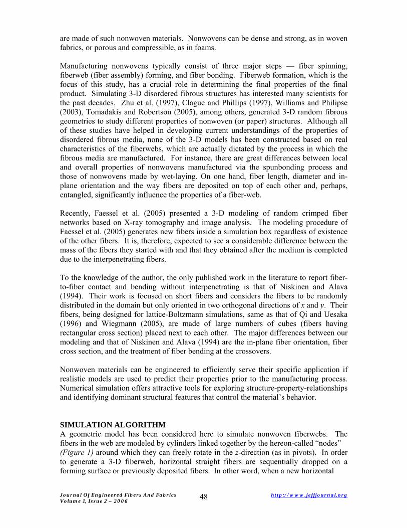
SIMULATION ALGORITHM A geometric model has been considered here to simulate nonwoven fiberwebs. The fibers in the web are modeled by cylinders linked together by the hereon-called “nodes” (Figure 1) around which they can freely rotate in the z-direction (as in pivots). In order to generate a 3-D fiberweb, horizontal straight fibers are sequentially dropped on a forming surface or previously deposited fibers. In other word, when a new horizontal
Journal Of Engineered Fibers And Fabrics http://www.jeffjournal.org Volume 1, Issue 2 – 2006
48
fiber is generated, both the web and the new fiber are projected onto the forming surface (the plane at z =0). A subset of the web is created from the projected fibers that intersect the projection of the new fiber. This subset will be used instead of the full web in order to speed up the computations. If there are no fibers underneath the new one, it will be directly placed on the forming surface and the procedure will restart. However, if the new fiber is likely to hit fibers from the web, the next step is to lower the new fiber on the web (i.e., to find the smallest vertical translation which will bring the new fiber in contact with the web) as shown in Figure 1. All those translations are computed and sorted. If there are several occurrences of a smallest value, all of the corresponding impact points are used. When a fiber falls on an existing fiber, a new node is generated on its axis and the fiber is split into two segments. Our algorithm allows for these new fiber segments to rotate downward around this node, emulating bending of the original fiber over the deposited one at the crossover.
a b
c d
Hea Tail
e
Hea Tail
f
Head Tail
Figure 1: Schematic of web generation algorithm. a) The new fiber is created above the web b) The fibers out of collision range are ignored c) The distances are computed and the smallest one is selected d) Bending the head of the fiber; the irrelevant fibers are ignored e) The bending angles are computed and the smallest one is selected f) The bending angle is compared to a maximum allowable angle; the angle is smaller than the maximum, we can bend the rest of the fiber
The angle by which the segments rotate is an input that can be used to influence the Solid Volume Fraction (SVF) of fiberweb. If fibers are stiff and expected not to bend, this
Journal Of Engineered Fibers And Fabrics http://www.jeffjournal.org Volume 1, Issue 2 – 2006
49
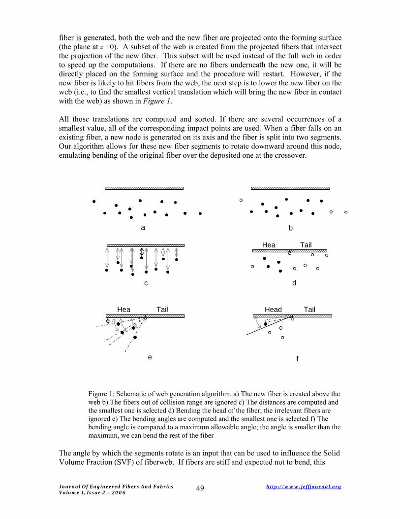
angle is set to zero and so the fibers stay horizontal during the deposition process. When the two segments rotate around their common node, small parts of them get inside the existing fiber as well as each other as shown in Figure 2.
NodeNode
Figure 2: Fiber interactions at a contact point
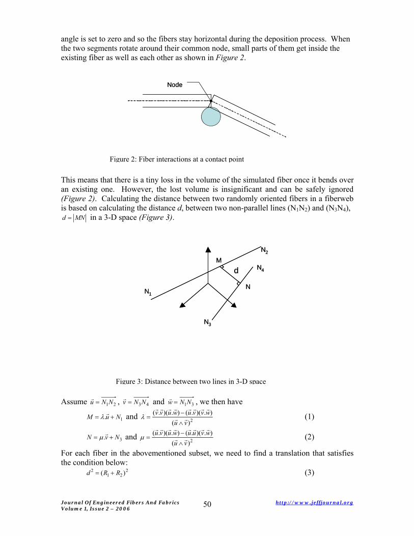
This means that there is a tiny loss in the volume of the simulated fiber once it bends over an existing one. However, the lost volume is insignificant and can be safely ignored (Figure 2). Calculating the distance between two randomly oriented fibers in a fiberweb is based on calculating the distance d, between two non-parallel lines (N1N2) and (N3N4),
MNd = in a 3-D space (Figure 3).
M
NN1
N2
N3
N4dM
NN1
N2
N3
N4d
Figure 3: Distance between two lines in 3-D space
Assume 21NNu =r , 43NNv =
r and 31NNw =r , we then have
1. NuM +=r
λ and 2)().)(.().)(.(
vuwvvuwuvv
rr
rrrrrrrr
∧−
=λ (1)
3. NvN +=r
μ and 2)().)(.().)(.(
vuwvuuwuvu
rr
rrrrrrrr
∧−
=μ (2)
For each fiber in the abovementioned subset, we need to find a translation that satisfies the condition below:
221
2 )( RRd += (3)
Journal Of Engineered Fibers And Fabrics http://www.jeffjournal.org Volume 1, Issue 2 – 2006
50
R1 and R2 are the radii of the new fiber and the examined fiber from the subset, respectively. Assume zr
r.ττ = to be the above translation, from Eq. 1, 2 and 3 one can
obtain a polynomial equation as follows (with the assumption that the new fiber is horizontal, i.e. ): 0z.u =
rr
[ ] 222
22
21 ).().(2).().(1)( wvuzwzvvu
uuzvRRrrrrrrr
rr
rrrr
−−++−⎥⎥⎦
⎤
⎢⎢⎣
⎡
∧−=+ μλτλτ (4)
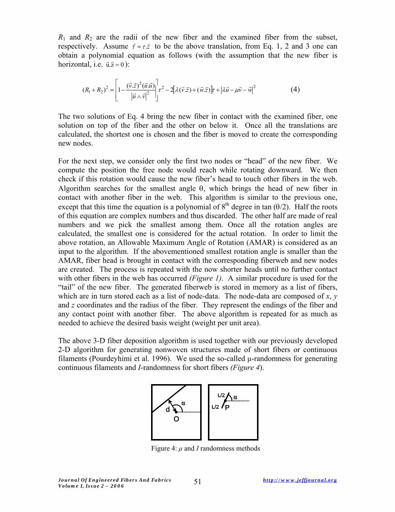
The two solutions of Eq. 4 bring the new fiber in contact with the examined fiber, one solution on top of the fiber and the other on below it. Once all the translations are calculated, the shortest one is chosen and the fiber is moved to create the corresponding new nodes. For the next step, we consider only the first two nodes or “head” of the new fiber. We compute the position the free node would reach while rotating downward. We then check if this rotation would cause the new fiber’s head to touch other fibers in the web. Algorithm searches for the smallest angle θ, which brings the head of new fiber in contact with another fiber in the web. This algorithm is similar to the previous one, except that this time the equation is a polynomial of 8th degree in tan (θ/2). Half the roots of this equation are complex numbers and thus discarded. The other half are made of real numbers and we pick the smallest among them. Once all the rotation angles are calculated, the smallest one is considered for the actual rotation. In order to limit the above rotation, an Allowable Maximum Angle of Rotation (AMAR) is considered as an input to the algorithm. If the abovementioned smallest rotation angle is smaller than the AMAR, fiber head is brought in contact with the corresponding fiberweb and new nodes are created. The process is repeated with the now shorter heads until no further contact with other fibers in the web has occurred (Figure 1). A similar procedure is used for the “tail” of the new fiber. The generated fiberweb is stored in memory as a list of fibers, which are in turn stored each as a list of node-data. The node-data are composed of x, y and z coordinates and the radius of the fiber. They represent the endings of the fiber and any contact point with another fiber. The above algorithm is repeated for as much as needed to achieve the desired basis weight (weight per unit area). The above 3-D fiber deposition algorithm is used together with our previously developed 2-D algorithm for generating nonwoven structures made of short fibers or continuous filaments (Pourdeyhimi et al. 1996). We used the so-called μ-randomness for generating continuous filaments and I-randomness for short fibers (Figure 4).
αd
O
αP
L/2
L/2α
dO
αd
O
αP
L/2
L/2
αP
L/2
L/2
Figure 4: μ and I randomness methods
Journal Of Engineered Fibers And Fabrics http://www.jeffjournal.org Volume 1, Issue 2 – 2006
51
In μ-randomness method, a line is defined by the perpendicular distance d from the center of the sample and the angular position of the perpendicular α. The distance d is sampled from a random distribution and the slope α from 90° minus a value from the Orientation Distribution Function (ODF). A line is then drawn perpendicular to the α-direction, distance d away from the center. In order to get a uniform web, the sample size must be increased by a factor 2 before the generation process and then cropped back to its original size. The sample must be square or temporarily expanded into a square. In I-randomness method, a point, P, is chosen at random by its coordinates such that it lies in a surface larger than the original sample size by length l. This ensures that edges of the sample are intersected by appropriate fibers of length l having their center of mass outside the sample. Next, a slope α is selected from the ODF and a segment of length l with slope α and with the point P as its middle is created. The sample is cropped to its original size and can be rectangular. Note that ODF can be measured via image processing for the case of thin nonwoven media. Readers are referred to the work of Pourdeyhimi et al. (1996) for more details on calculating ODF of thin nonwovens. If the medium is not thin enough to allow backlight imaging and processing, it can only be estimated based on the characteristics of the fiber-web formation technique. For instance, fiber-webs produced via carding process are known to have fibers which are slightly oriented towards the direction where fiber-web leaves the machine (the so-called machine direction), while air-laid fiber-webs have fibers with almost random orientations. The algorithm outlined in this paper can generate virtual 3-D structures of un-bonded fiberwebs of different fiber lengths, from very short to infinitely long (continuous filaments), a blend of fibers with different diameters, and fiberwebs of different ODFs. These features are fully explained and analyzed in the following sections. PROPERTIES OF MONODIAMETER VIRTUAL FIBROUS WEBS In this section, we present our modeling strategies for simulating different fibrous materials. In the subsequent sections, structural properties of different fiberwebs are presented and their differences are discussed. These cases are basically the fiberwebs that can be attained from different web manufacturing processes. We also discuss potential applications of such fiberwebs whenever possible. All the fibers will be assumed to have a density of 0.9. Modeling Fibrous Webs Made of Infinitely Long Fibers Here, we assume that fibers are infinitely long. Nonwovens made of spunbonding (SB), meltblowing (MB), and electrospinning (ES) are typical examples of fiberwebs made of infinitely long fibers. The common characteristic among SB, MB, and ES is that in all of them a continuous polymeric filament at liquid state in being attenuated to reduce its diameter from few hundred micrometers down to few hundred nanometers. SB and MB use high-speed air-jets to draw the filaments where ES takes advantage of the instabilities that grow on a filament when exposed to a strong electric field. These fibers solidify during the attenuation, form irregular and large coils (thousands of times larger than the filament diameter) and deposit sequentially on a substrate or previously deposited fibers. These fiberwebs are 3-D layered structures consisting of a large number of continuous filaments randomly distributed in a horizontal plane and sequentially deposited on top of
Journal Of Engineered Fibers And Fabrics http://www.jeffjournal.org Volume 1, Issue 2 – 2006
52
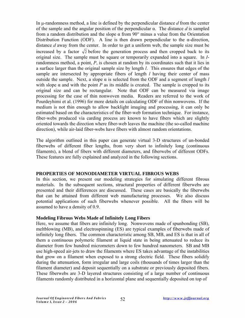
each others to build up a 3-D geometry. Figure 5 shows microscopic images of typical nonwoven webs made by spunbonding, meltblowing, and electrospinning.
10 µm100 µm 500 µm
a b c
10 µm100 µm 500 µm
a b c
Figure 5: Microscopic images of a) Meltblown, b) Spunbonded and c) Electro-spun fiber-webs
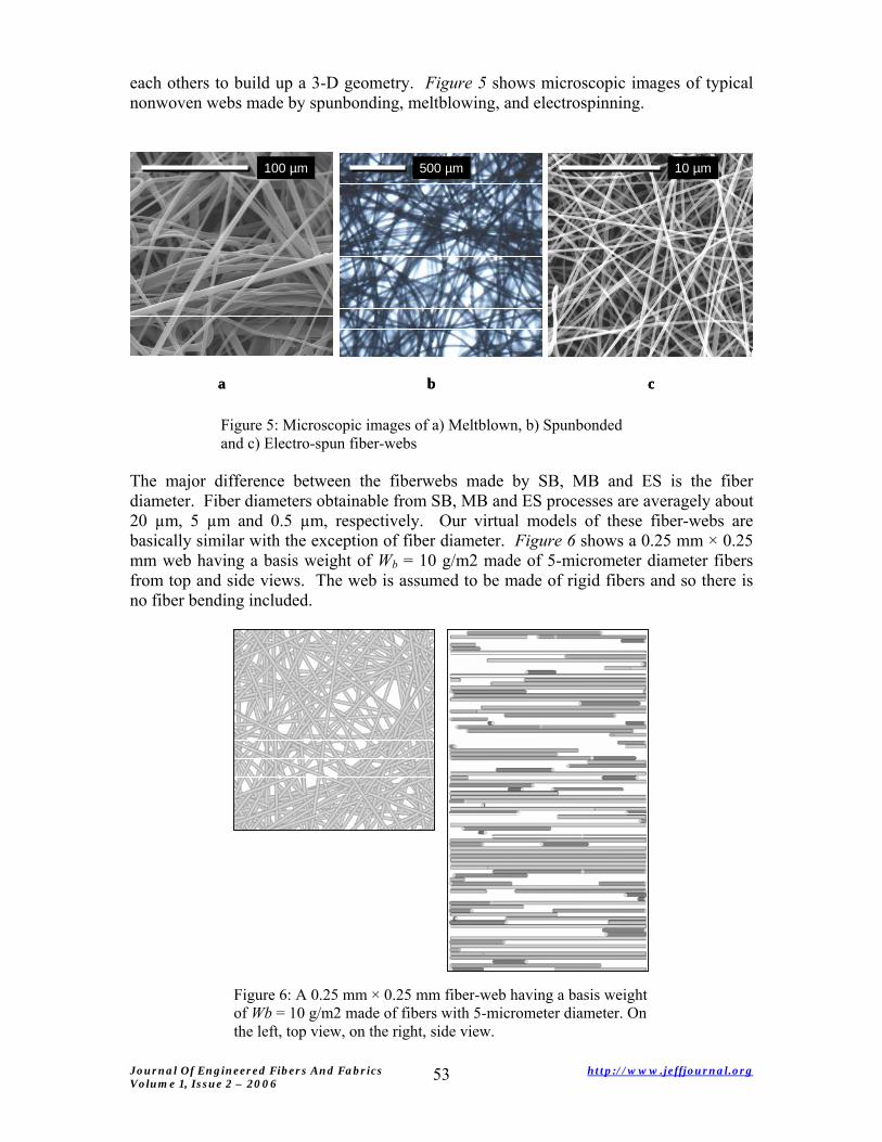
The major difference between the fiberwebs made by SB, MB and ES is the fiber diameter. Fiber diameters obtainable from SB, MB and ES processes are averagely about 20 µm, 5 µm and 0.5 µm, respectively. Our virtual models of these fiber-webs are basically similar with the exception of fiber diameter. Figure 6 shows a 0.25 mm × 0.25 mm web having a basis weight of Wb = 10 g/m2 made of 5-micrometer diameter fibers from top and side views. The web is assumed to be made of rigid fibers and so there is no fiber bending included.
Figure 6: A 0.25 mm × 0.25 mm fiber-web having a basis weight of Wb = 10 g/m2 made of fibers with 5-micrometer diameter. On the left, top view, on the right, side view.
Journal Of Engineered Fibers And Fabrics http://www.jeffjournal.org Volume 1, Issue 2 – 2006
53
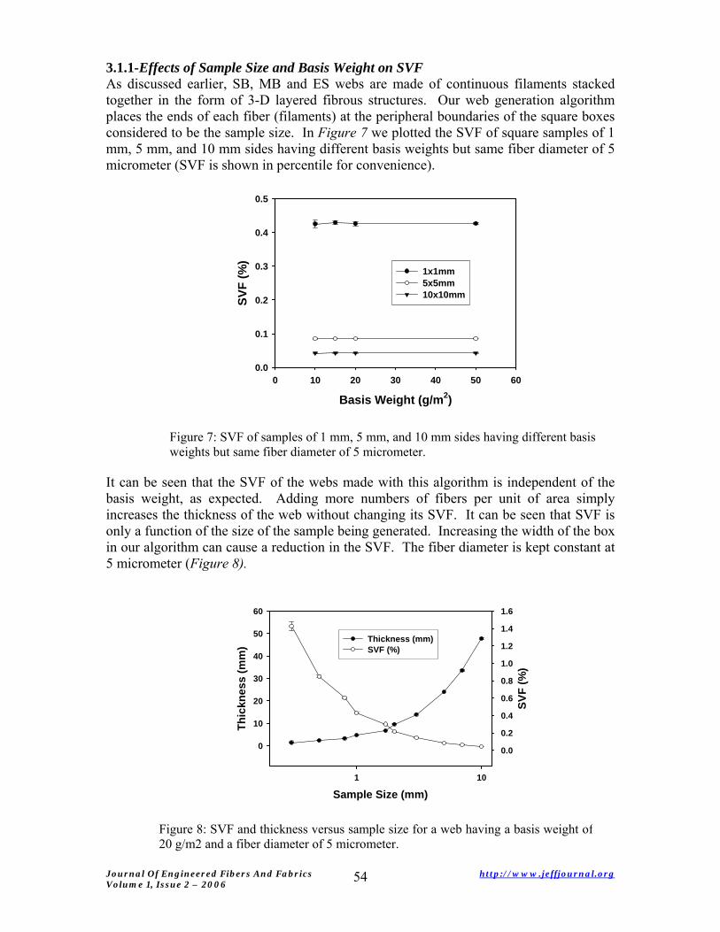
3.1.1-Effects of Sample Size and Basis Weight on SVF As discussed earlier, SB, MB and ES webs are made of continuous filaments stacked together in the form of 3-D layered fibrous structures. Our web generation algorithm places the ends of each fiber (filaments) at the peripheral boundaries of the square boxes considered to be the sample size. In Figure 7 we plotted the SVF of square samples of 1 mm, 5 mm, and 10 mm sides having different basis weights but same fiber diameter of 5 micrometer (SVF is shown in percentile for convenience).
Basis Weight (g/m2)0 10 20 30 40 50 60
SVF
(%)
0.0
0.1
0.2
0.3
0.4
0.5
1x1mm5x5mm10x10mm
Figure 7: SVF of samples of 1 mm, 5 mm, and 10 mm sides having different basis weights but same fiber diameter of 5 micrometer.
It can be seen that the SVF of the webs made with this algorithm is independent of the basis weight, as expected. Adding more numbers of fibers per unit of area simply increases the thickness of the web without changing its SVF. It can be seen that SVF is only a function of the size of the sample being generated. Increasing the width of the box in our algorithm can cause a reduction in the SVF. The fiber diameter is kept constant at 5 micrometer (Figure 8).
Sample Size (mm)1 10
Thic
knes
s (m
m)
0
10
20
30
40
50
60
SVF
(%)
0.0
0.2
0.4
0.6
0.8
1.0
1.2
1.4
1.6
Thickness (mm)SVF (%)
Figure 8: SVF and thickness versus sample size for a web having a basis weight of20 g/m2 and a fiber diameter of 5 micrometer.
Journal Of Engineered Fibers And Fabrics http://www.jeffjournal.org Volume 1, Issue 2 – 2006
54
The rapid decrease in the SVF with increasing sample size is evident. Note that obviously the SVF of a real web is independent of the sample size as long as the sample size is sufficiently larger than the smallest length scale in the medium. Defining the length scale in a fibrous medium is very difficult especially in the cases where fibers have no finite length such as spunbond filters. Spunbond filters are made of continuous filaments curled, coiled and stacked on top of each other. Generating such a fiberweb is mathematically extremely difficult because it requires the radius of curvature of the filaments at each point in the 3-D space. For this reason, we model such structures with straight cylinders extending almost from one end of the sample to the other. This causes the SVF to become dependent on the sample size and one needs to use the relevant sample size to simulate a given nonwoven sheet. The origin of this counter-intuitive property of the simulation is that on average, the number of fibers per layer is relatively independent of the sample size, whereas their length is not. As a consequence, when changing the sample size, the total volume of the fibers is going to vary linearly while the sample volume varies as the square of the sample size. It should be considered that since the fibers are extended from one end of the sample to the other, when the basis weight is kept constant, large samples will have a greater thickness as compared to small ones (Figure 8). As expected, product of SVF and thickness is constant ( ). Results shown in Figures 7 and 8 are averaged over an ensemble of 10 webs.
220 mgWtSVF bf /==×× ρ
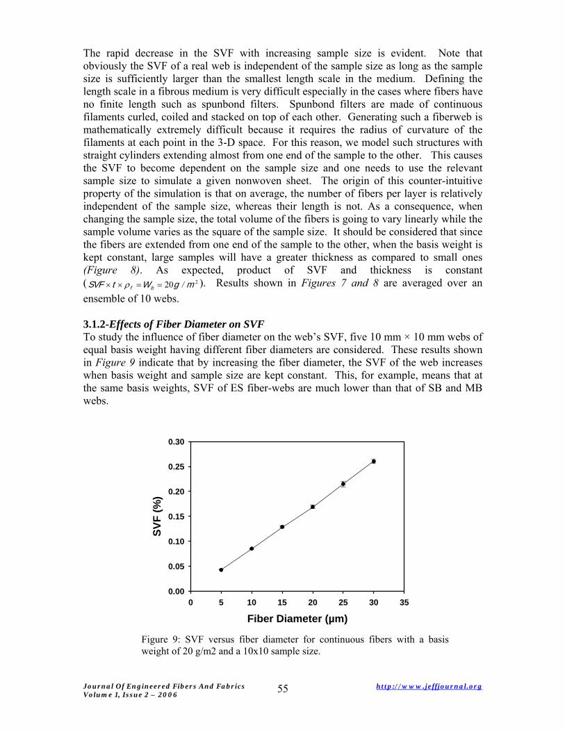
3.1.2-Effects of Fiber Diameter on SVF To study the influence of fiber diameter on the web’s SVF, five 10 mm × 10 mm webs of equal basis weight having different fiber diameters are considered. These results shown in Figure 9 indicate that by increasing the fiber diameter, the SVF of the web increases when basis weight and sample size are kept constant. This, for example, means that at the same basis weights, SVF of ES fiber-webs are much lower than that of SB and MB webs.
Fiber Diameter (µm)0 5 10 15 20 25 30 35
SVF
(%)
0.00
0.05
0.10
0.15
0.20
0.25
0.30
Figure 9: SVF versus fiber diameter for continuous fibers with a basis weight of 20 g/m2 and a 10x10 sample size.
Journal Of Engineered Fibers And Fabrics http://www.jeffjournal.org Volume 1, Issue 2 – 2006
55
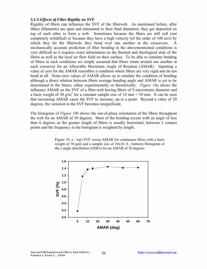
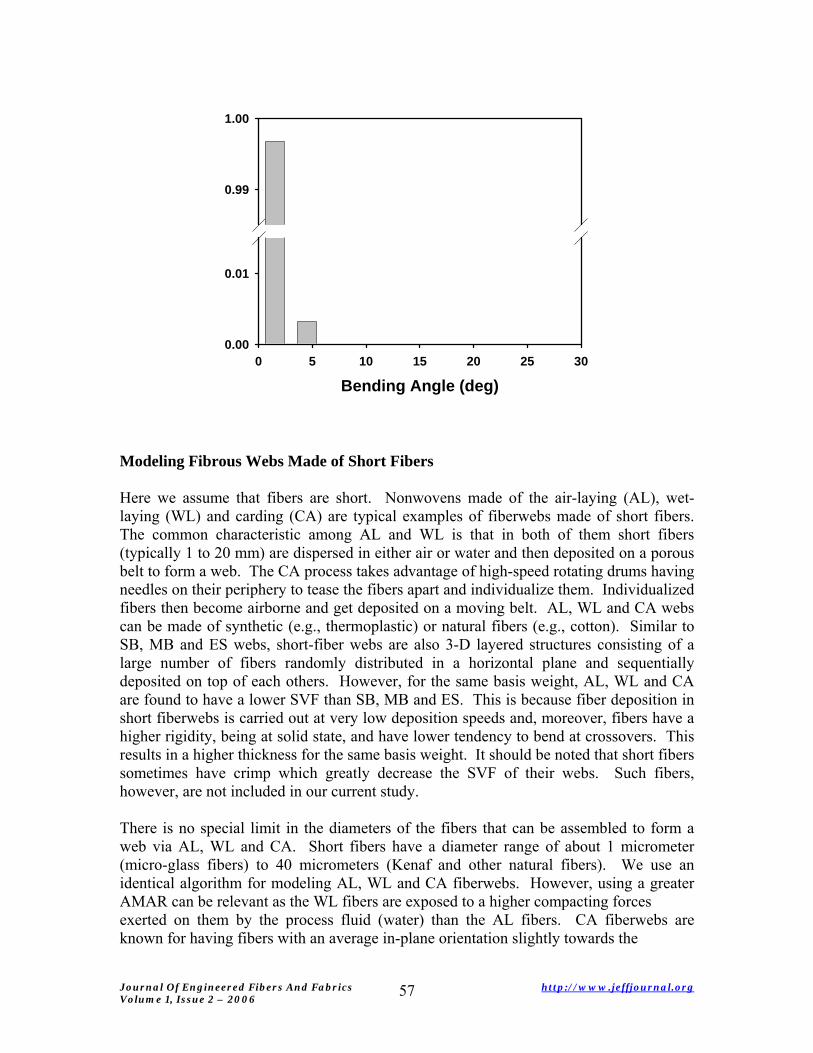
3.1.3-Effects of Fiber Rigidity on SVF Rigidity of fibers can influence the SVF of the fiberweb. As mentioned before, after fibers (filaments) are spun and attenuated to their final diameters, they get deposited on top of each other to form a web. Sometimes because the fibers are still soft (not completely solidified) or because they have a high velocity (of the order of 100 m/s) by which they hit the fiberweb, they bend over one another at the crossovers. A mechanically accurate prediction of fiber bending in the abovementioned conditions is very difficult as it requires exact information on the thermal and rheological state of the fibers as well as the local air flow field on their surface. To be able to simulate bending of fibers in such conditions we simply assumed that fibers rotate around one another at each crossover for an Allowable Maximum Angle of Rotation (AMAR). Inputting a value of zero for the AMAR resembles a condition where fibers are very rigid and do not bend at all. None-zero values of AMAR allows us to emulate the condition of bending although a direct relation between fibers average bending angle and AMAR is yet to be determined in the future, either experimentally or theoretically. Figure 10a shows the influence AMAR on the SVF of a fiber-web having fibers of 5-micrometer diameter and a basis weight of 30 g/m2 for a constant sample size of 10 mm × 10 mm. It can be seen that increasing AMAR cause the SVF to increase, up to a point. Beyond a value of 20 degrees, the variation in the SVF becomes insignificant. The histogram of Figure 10b shows the out-of-plane orientation of the fibers throughout the web for an AMAR of 30 degrees. Most of the bending occurs with an angle of less than 6 degrees as the greater length of fibers is usually horizontal, between 2 contact points and the frequency in the histogram is weighted by length.
Figure 10: a - top) SVF versus AMAR for continuous fibers with a basisweight of 30 gsm and a sample size of 10x10. b - bottom) Histogram of the z-angle distribution (ODFz) for an AMAR of 30 degrees
AMAR (deg)0 10 20 30 40 50 60 70
SVF
(%)
0.0
0.2
0.4
0.6
0.8
1.0
1.2
1.4
1.6
Journal Of Engineered Fibers And Fabrics http://www.jeffjournal.org Volume 1, Issue 2 – 2006
56
Bending Angle (deg)0 5 10 15 20 25 30
0.00
0.01
0.99
1.00
Modeling Fibrous Webs Made of Short Fibers
Here we assume that fibers are short. Nonwovens made of the air-laying (AL), wet-laying (WL) and carding (CA) are typical examples of fiberwebs made of short fibers. The common characteristic among AL and WL is that in both of them short fibers (typically 1 to 20 mm) are dispersed in either air or water and then deposited on a porous belt to form a web. The CA process takes advantage of high-speed rotating drums having needles on their periphery to tease the fibers apart and individualize them. Individualized fibers then become airborne and get deposited on a moving belt. AL, WL and CA webs can be made of synthetic (e.g., thermoplastic) or natural fibers (e.g., cotton). Similar to SB, MB and ES webs, short-fiber webs are also 3-D layered structures consisting of a large number of fibers randomly distributed in a horizontal plane and sequentially deposited on top of each others. However, for the same basis weight, AL, WL and CA are found to have a lower SVF than SB, MB and ES. This is because fiber deposition in short fiberwebs is carried out at very low deposition speeds and, moreover, fibers have a higher rigidity, being at solid state, and have lower tendency to bend at crossovers. This results in a higher thickness for the same basis weight. It should be noted that short fibers sometimes have crimp which greatly decrease the SVF of their webs. Such fibers, however, are not included in our current study. There is no special limit in the diameters of the fibers that can be assembled to form a web via AL, WL and CA. Short fibers have a diameter range of about 1 micrometer (micro-glass fibers) to 40 micrometers (Kenaf and other natural fibers). We use an identical algorithm for modeling AL, WL and CA fiberwebs. However, using a greater AMAR can be relevant as the WL fibers are exposed to a higher compacting forces exerted on them by the process fluid (water) than the AL fibers. CA fiberwebs are known for having fibers with an average in-plane orientation slightly towards the
Journal Of Engineered Fibers And Fabrics http://www.jeffjournal.org Volume 1, Issue 2 – 2006
57
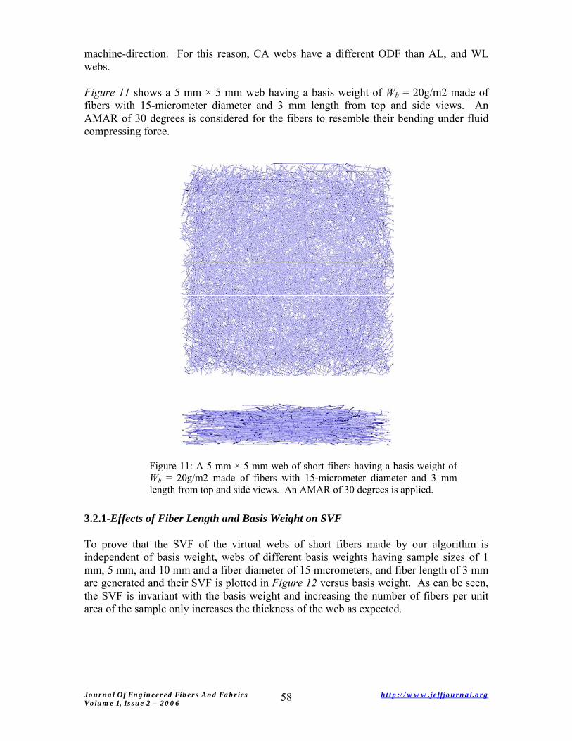
machine-direction. For this reason, CA webs have a different ODF than AL, and WL webs. Figure 11 shows a 5 mm × 5 mm web having a basis weight of Wb = 20g/m2 made of fibers with 15-micrometer diameter and 3 mm length from top and side views. An AMAR of 30 degrees is considered for the fibers to resemble their bending under fluid compressing force.
Figure 11: A 5 mm × 5 mm web of short fibers having a basis weight ofWb = 20g/m2 made of fibers with 15-micrometer diameter and 3 mmlength from top and side views. An AMAR of 30 degrees is applied.
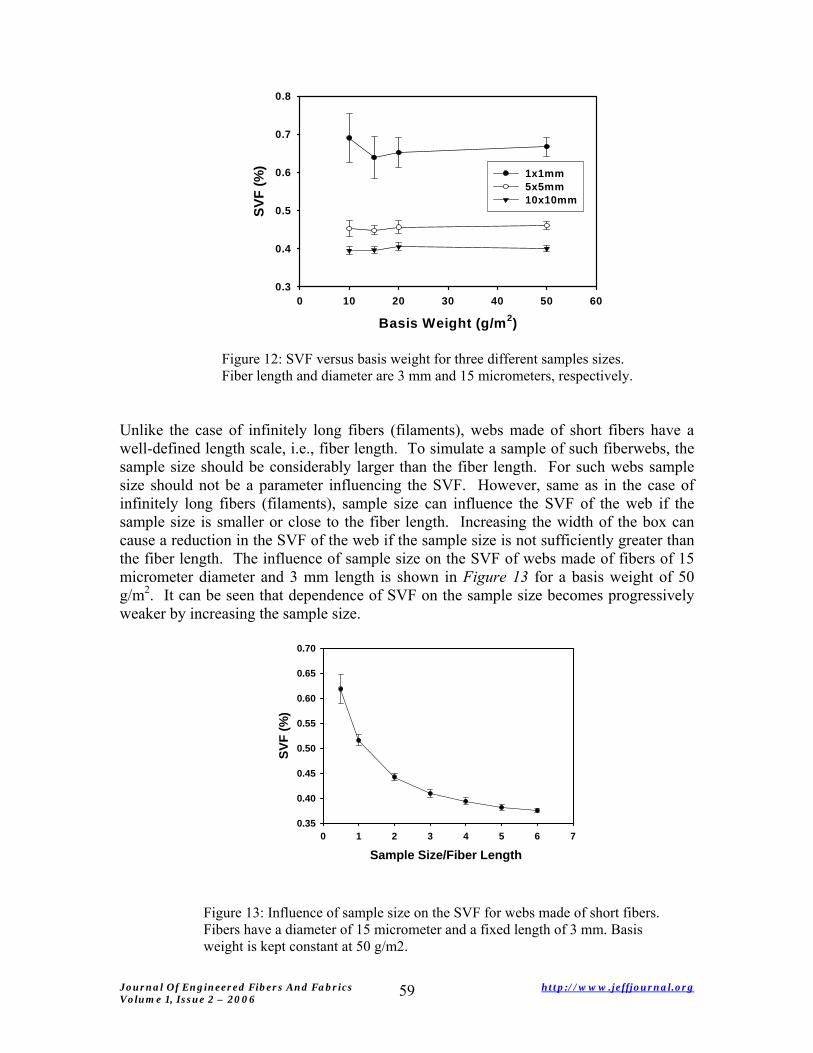
3.2.1-Effects of Fiber Length and Basis Weight on SVF
To prove that the SVF of the virtual webs of short fibers made by our algorithm is independent of basis weight, webs of different basis weights having sample sizes of 1 mm, 5 mm, and 10 mm and a fiber diameter of 15 micrometers, and fiber length of 3 mm are generated and their SVF is plotted in Figure 12 versus basis weight. As can be seen, the SVF is invariant with the basis weight and increasing the number of fibers per unit area of the sample only increases the thickness of the web as expected.
Journal Of Engineered Fibers And Fabrics http://www.jeffjournal.org Volume 1, Issue 2 – 2006
58
Basis Weight (g/m2)0 10 20 30 40 50 60
SVF
(%)
0.3
0.4
0.5
0.6
0.7
0.8
1x1mm5x5mm10x10mm
Figure 12: SVF versus basis weight for three different samples sizes. Fiber length and diameter are 3 mm and 15 micrometers, respectively.
Unlike the case of infinitely long fibers (filaments), webs made of short fibers have a well-defined length scale, i.e., fiber length. To simulate a sample of such fiberwebs, the sample size should be considerably larger than the fiber length. For such webs sample size should not be a parameter influencing the SVF. However, same as in the case of infinitely long fibers (filaments), sample size can influence the SVF of the web if the sample size is smaller or close to the fiber length. Increasing the width of the box can cause a reduction in the SVF of the web if the sample size is not sufficiently greater than the fiber length. The influence of sample size on the SVF of webs made of fibers of 15 micrometer diameter and 3 mm length is shown in Figure 13 for a basis weight of 50 g/m2. It can be seen that dependence of SVF on the sample size becomes progressively weaker by increasing the sample size.
Sample Size/Fiber Length0 1 2 3 4 5 6 7
SVF
(%)
0.35
0.40
0.45
0.50
0.55
0.60
0.65
0.70
Figure 13: Influence of sample size on the SVF for webs made of short fibers. Fibers have a diameter of 15 micrometer and a fixed length of 3 mm. Basis weight is kept constant at 50 g/m2.
Journal Of Engineered Fibers And Fabrics http://www.jeffjournal.org Volume 1, Issue 2 – 2006
59
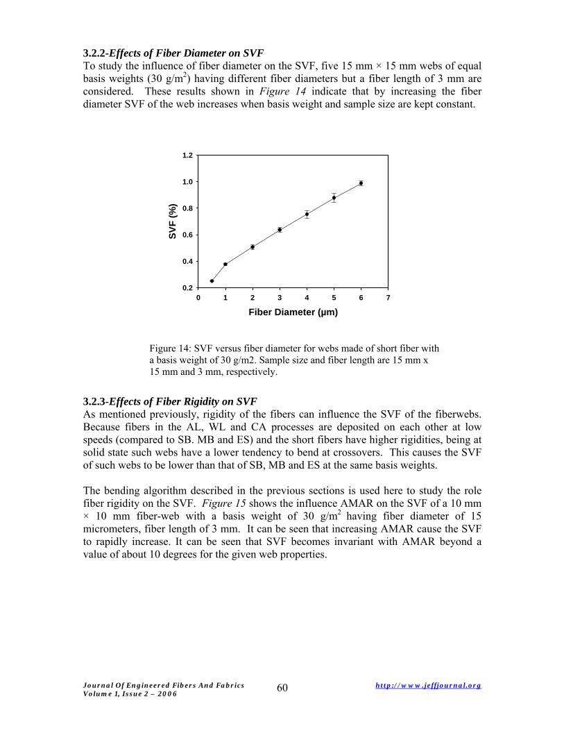
3.2.2-Effects of Fiber Diameter on SVF To study the influence of fiber diameter on the SVF, five 15 mm × 15 mm webs of equal basis weights (30 g/m2) having different fiber diameters but a fiber length of 3 mm are considered. These results shown in Figure 14 indicate that by increasing the fiber diameter SVF of the web increases when basis weight and sample size are kept constant.
Fiber Diameter (µm)0 1 2 3 4 5 6 7
SVF
(%)
0.2
0.4
0.6
0.8
1.0
1.2
Figure 14: SVF versus fiber diameter for webs made of short fiber with a basis weight of 30 g/m2. Sample size and fiber length are 15 mm x 15 mm and 3 mm, respectively.
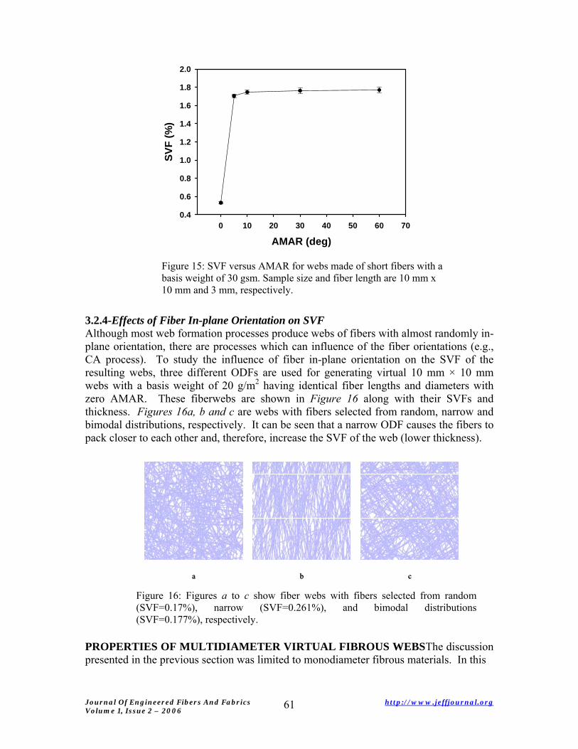
3.2.3-Effects of Fiber Rigidity on SVF As mentioned previously, rigidity of the fibers can influence the SVF of the fiberwebs. Because fibers in the AL, WL and CA processes are deposited on each other at low speeds (compared to SB. MB and ES) and the short fibers have higher rigidities, being at solid state such webs have a lower tendency to bend at crossovers. This causes the SVF of such webs to be lower than that of SB, MB and ES at the same basis weights. The bending algorithm described in the previous sections is used here to study the role fiber rigidity on the SVF. Figure 15 shows the influence AMAR on the SVF of a 10 mm × 10 mm fiber-web with a basis weight of 30 g/m2 having fiber diameter of 15 micrometers, fiber length of 3 mm. It can be seen that increasing AMAR cause the SVF to rapidly increase. It can be seen that SVF becomes invariant with AMAR beyond a value of about 10 degrees for the given web properties.
Journal Of Engineered Fibers And Fabrics http://www.jeffjournal.org Volume 1, Issue 2 – 2006
60
AMAR (deg)0 10 20 30 40 50 60 70
SVF
(%)
0.4
0.6
0.8
1.0
1.2
1.4
1.6
1.8
2.0
Figure 15: SVF versus AMAR for webs made of short fibers with abasis weight of 30 gsm. Sample size and fiber length are 10 mm x 10 mm and 3 mm, respectively.
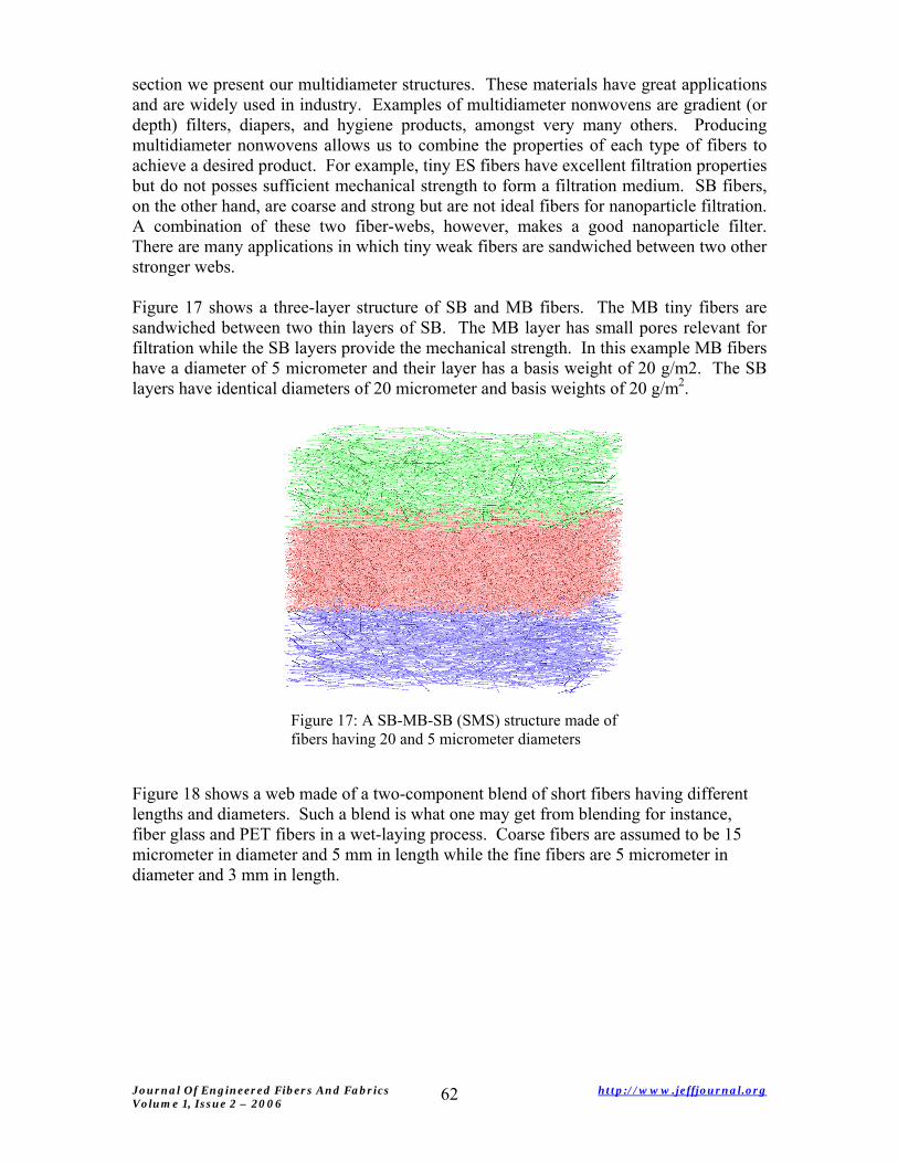
3.2.4-Effects of Fiber In-plane Orientation on SVF Although most web formation processes produce webs of fibers with almost randomly in-plane orientation, there are processes which can influence of the fiber orientations (e.g., CA process). To study the influence of fiber in-plane orientation on the SVF of the resulting webs, three different ODFs are used for generating virtual 10 mm × 10 mm webs with a basis weight of 20 g/m2 having identical fiber lengths and diameters with zero AMAR. These fiberwebs are shown in Figure 16 along with their SVFs and thickness. Figures 16a, b and c are webs with fibers selected from random, narrow and bimodal distributions, respectively. It can be seen that a narrow ODF causes the fibers to pack closer to each other and, therefore, increase the SVF of the web (lower thickness).
a b ca b c
Figure 16: Figures a to c show fiber webs with fibers selected from random(SVF=0.17%), narrow (SVF=0.261%), and bimodal distributions(SVF=0.177%), respectively.
PROPERTIES OF MULTIDIAMETER VIRTUAL FIBROUS WEBSThe discussion presented in the previous section was limited to monodiameter fibrous materials. In this
Journal Of Engineered Fibers And Fabrics http://www.jeffjournal.org Volume 1, Issue 2 – 2006
61
section we present our multidiameter structures. These materials have great applications and are widely used in industry. Examples of multidiameter nonwovens are gradient (or depth) filters, diapers, and hygiene products, amongst very many others. Producing multidiameter nonwovens allows us to combine the properties of each type of fibers to achieve a desired product. For example, tiny ES fibers have excellent filtration properties but do not posses sufficient mechanical strength to form a filtration medium. SB fibers, on the other hand, are coarse and strong but are not ideal fibers for nanoparticle filtration. A combination of these two fiber-webs, however, makes a good nanoparticle filter. There are many applications in which tiny weak fibers are sandwiched between two other stronger webs. Figure 17 shows a three-layer structure of SB and MB fibers. The MB tiny fibers are sandwiched between two thin layers of SB. The MB layer has small pores relevant for filtration while the SB layers provide the mechanical strength. In this example MB fibers have a diameter of 5 micrometer and their layer has a basis weight of 20 g/m2. The SB layers have identical diameters of 20 micrometer and basis weights of 20 g/m2.
Figure 17: A SB-MB-SB (SMS) structure made of fibers having 20 and 5 micrometer diameters
Figure 18 shows a web made of a two-component blend of short fibers having different lengths and diameters. Such a blend is what one may get from blending for instance, fiber glass and PET fibers in a wet-laying process. Coarse fibers are assumed to be 15 micrometer in diameter and 5 mm in length while the fine fibers are 5 micrometer in diameter and 3 mm in length.
Journal Of Engineered Fibers And Fabrics http://www.jeffjournal.org Volume 1, Issue 2 – 2006
62
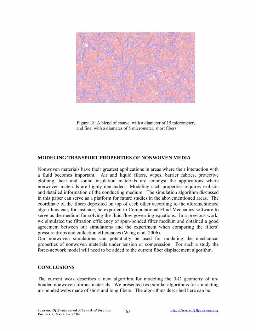
Figure 18: A blend of coarse, with a diameter of 15 micrometer, and fine, with a diameter of 5 micrometer, short fibers.
MODELING TRANSPORT PROPERTIES OF NONWOVEN MEDIA
Nonwoven materials have their greatest applications in areas where their interaction with a fluid becomes important. Air and liquid filters, wipes, barrier fabrics, protective clothing, heat and sound insulation materials are amongst the applications where nonwoven materials are highly demanded. Modeling such properties requires realistic and detailed information of the conducting medium. The simulation algorithm discussed in this paper can serve as a platform for future studies in the abovementioned areas. The coordinate of the fibers deposited on top of each other according to the aforementioned algorithms can, for instance, be exported to Computational Fluid Mechanics software to serve as the medium for solving the fluid flow governing equations. In a previous work, we simulated the filtration efficiency of spun-bonded filter medium and obtained a good agreement between our simulations and the experiment when comparing the filters’ pressure drops and collection efficiencies (Wang et al. 2006). Our nonwoven simulations can potentially be used for modeling the mechanical properties of nonwoven materials under tension or compression. For such a study the force-network model will need to be added to the current fiber displacement algorithm.
CONCLUSIONS
The current work describes a new algorithm for modeling the 3-D geometry of un-bonded nonwoven fibrous materials. We presented two similar algorithms for simulating un-bonded webs made of short and long fibers. The algorithms described here can be
Journal Of Engineered Fibers And Fabrics http://www.jeffjournal.org Volume 1, Issue 2 – 2006
63
used for modeling the 3-D geometry of the fiber-webs made by Electro-spinning, Melt-blowing, Spun-bonding, Wet-laying, Air-laying and Carding. The SVF of the webs developed according to the above processes are studied as a function of fiber length, diameter, and bending rigidity as well as the web basis weight and sample size. It is shown that our algorithms generate structures with their SVF being independent of the basis weight as observed in practice. It is demonstrated that decreasing the fiber diameter while keeping other properties constant results in a decrease in SVF of the fiber-web in a linear fashion. The same dependency, however, is not observed when decreasing the fibers’ rigidity. Our algorithms allow one to simulate fibrous webs made of layers of different fiber types in accordance to industrial applications composite and/or sandwiched materials. It is worth mentioning that our virtual fibrous structures can be of great help in modeling transport phenomena through nonwoven materials. Such simulations can also be used in modeling the mechanical response of such compliant materials under tension or compression.
ACKNOWLEDGEMENT
The current work was supported by a grant from the Nonwovens Cooperative Research Center. Their support is gratefully acknowledged.
REFERENCES 1. Zhu Y.T., Blumenthal W.R., Lowe T.C., Determination of non-symmetric 3-D fiber-
orientation distribution and average fiber length in short-fiber composites, Journal of Composite Materials 31 (13): 1287-1301 (1997)
2. Clague, D.S., Phillips, R.J., 1997. A numerical calculation of the hydraulic
permeability of three-dimensional disordered fibrous media, Physics of Fluids 9 (6), 1562-1572.
3. Williams S. R., Philipse A. P., Random packing of spheres and spherocylinders
simulated by mechanical contraction, Physical Review E 67 (5): Art. No. 051301 Part 1, (2003)
4. Tomadakis M. M., Robertson T. J., Viscous permeability of random fiber structures:
Comparison of electrical and diffusional estimates with experimental and analytical results, Journal of Composites Materials 39(2): 163-188 (2005)
5. Niskanen K. J., and Alava M. J., Planar random network with flexible fibers, Physical
Review Letters 73 (25): 3475-3478 (1994) 6. Qi D., Uesaka T., Numerical experiments on paper-fluid interaction - Permeability of
a three-dimensional anisotropic fiber network, Journal of Material Science 31 (18): 4865-4870 SEP 15 1996
Journal Of Engineered Fibers And Fabrics http://www.jeffjournal.org Volume 1, Issue 2 – 2006
64
7. Faessel M., Delisee C., Bos F., Castera P., 3D Modeling of random cellulosic fibrous
networks based on X-ray tomography and image analysis, Composites Science & Technology 65 (13): 1931-1940 (2005)
8. Wiegmann A. (2005), http://www.geodict.com/workshop04.php 9. B. Pourdeyhimi, R. Ramanathan and R. Dent, Measurement of Fiber Orientation in
Nonwovens, Part 1, Simulation, Textile Research Journal, 66, (11), 713-722, (1996). 10. B. Pourdeyhimi, R. Ramanathan and R. Dent, Measurement of Fiber Orientation in
Nonwovens, Part 2: Direct Tracking, Textile Research Journal, 66, (12), 747-753, (1996)
11. Pourdeyhimi, B., Dent, R. and Davis, H., Measuring Fiber Orientation in Nonwovens,
Part III: Fourier Transform, Textile Research Journal, 67, 143-151 (1997) 12. Pourdeyhimi, B., Dent, R., Jerbi, A., Tanaka, S. and Deshpande, A., Measuring Fiber
Orientation in Nonwovens, Part V: Real Webs, Textile Research Journal, 67, 143-151 (1997)
13. Wang, Q., Maze, B., Vahedi Tafreshi, H., and Pourdeyhimi, B., A Case Study of
Simulating Nanoparticle Filtration via Spun-bonded Filter Media, Chemical Engineering Science , 61 ,4871-4883 (2006)
AUTHORS ADDRESSES Behnam Pourdeyhimi, Ph.D., Benoit Mazé, Ph.D., Hooman Vahedi Tafreshi, Ph.D. North Carolina State University Nonwovens Cooperative Research Center 2401 Research Drive Raleigh, North Carolina 27695-8301 USA
Journal Of Engineered Fibers And Fabrics http://www.jeffjournal.org Volume 1, Issue 2 – 2006
65