Embed Size (px)
Citation preview

3D Ultrasonic Wave Simulations for
Structural Health Monitoring
Cara A.C. Leckey
Nondestructive Evaluation
Sciences Branch
NASA Langley Research Center
Mark Hinders and Corey Miller
Nondestructive Evaluation Laboratory
College of William &Mary
12th International Symposium on Nondestructive Characterization of MaterialsVirginia Tech, Blacksburg, VA, USA
June 19-24, 2011

Overview• Lamb waves
– Structural health monitoring (SHM)
• Numerical modeling
– Elastodynamic finite integration technique (EFIT)
– 3D Simulations
• Comparison to experiment
• Anisotropic EFIT for composites
6/27/2011

Overview• Lamb waves
– Structural health monitoring (SHM)
• Numerical modeling
– Elastodynamic finite integration technique (EFIT)
– 3D Simulations
• Comparison to experiment
• Anisotropic EFIT for composites
6/27/2011

Lamb Waves• Guided ultrasonic waves:
– Created due to boundaries
– Interaction of coupled L and SV with boundaries leads to various modes
– A and S Lamb wave modes are created in isotropic plates
– Waves are dispersive: group and phase velocity depends on frequency-thickness
• Useful for interrogating plate-like materials– Detect damage before failure of key components
4
Symmetric Lamb wave mode
Antisymmetric Lamb wave mode
6/27/2011

Lamb Waves for SHM• Active interrogation method
• Propagate long distances in plates/pipes
– Tens of meters [Leonard and Hinders 2005]
– Leads to fewer sensors
• Lightweight mounted or embedded sensors
– Piezoelectric wafer sensors [Giurgiutiu and Cuc 2005]
– Macro fiber composite (MFC) piezoceramic fiber-matrix transducer [Collet et al. 2011]
• Ideal cases: Extent of damage can be found from mode arrival time changes [Bingham and Hinders 2009]
• Need to understand Lamb wave interaction with flaws to optimize techniques MFC
Image from www.smart-material.com
Piezo wafers
Image from www.steminc.com
6/27/2011

Overview• Lamb waves
– Structural health monitoring (SHM)
• Numerical modeling
– Elastodynamic finite integration technique (EFIT)
– 3D Simulations
• Comparison to experiment
• Anisotropic EFIT for composites
6/27/2011

Numerical Methods: FIT
• Until recently most elastic wave simulations were 2D
• FIT, FD, FEM
• Finite Integration Technique benefits
– Straight-forward equations
– Implemented in any programming language
• Parallelize for cluster computing
– Simple to incorporate boundary conditions
– Staggered grid means good stability
– Can handle large simulation spaces
6/27/2011 7

Elastodynamic FIT• Start with isotropic equations of motion:
• Discretization yields 9 equations [Fellinger 1995]
– Stability conditions define spatial and time steps
8

Parallel Processing
• Finite integration code is parallel– MPI, 1D virtual topology
• Runs on computing clusters
6/27/2011 9
Each
processor has
entire width
and depth
Stress and velocity information is passed between processors

EFIT: Lamb Waves• Dispersion curves for aircraft grade aluminum
– Group and phase velocity:
• EFIT result: 1.56 MHz mm• Higher MHz mm regions
– Complicated scattering
6/27/2011
dk
dcg
kcp
S0
A0
S1
A1
S2
A2
S0
A0
S1
A1
S2 A2S3
A3
S3
A3

Overview• Lamb waves
– Structural health monitoring (SHM)
• Numerical modeling
– Elastodynamic finite integration technique (EFIT)
– 3D Simulations
• Comparison to experiment
• Anisotropic EFIT for composites
6/27/2011
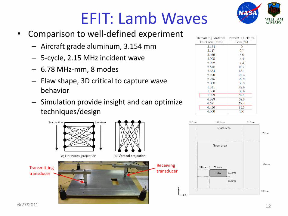
EFIT: Lamb Waves• Comparison to well-defined experiment
– Aircraft grade aluminum, 3.154 mm
– 5-cycle, 2.15 MHz incident wave
– 6.78 MHz-mm, 8 modes
– Flaw shape, 3D critical to capture wave behavior
– Simulation provide insight and can optimize techniques/design
12
Transmitting transducer
Receivingtransducer
6/27/2011

EFIT: Lamb Waves• 3D output: Visualizing data for useful analysis
Experimental data
Denoisedexperimental
data
EFIT A-scan
t1 t2 t3

EFIT: Lamb Waves• 1400 CPU hours per simulation (~45 wall-clock hours)
• Spatial step λ/15 (0.097 mm), time step 10 ns
• Four chosen transmitter positions
14
99.0 mm

Transmitter Position 1• 2.7 mm deep void, 85% material loss
• 0.98 MHz-mm, expect 2 modes beneath void
6/27/2011 15
S0
A0
S1
A1
S2
A2
S0
A0
S1
A1
S2 A2
S3
A3
S3
A3

Transmitter Position 1• Based on EFIT: expect 6 modes and later high amplitude S0 and A0
• Creation of low phase velocity waves in thinned region
• White lines are regions beneath void
6/27/2011 16
(a) 27 µs (b) 36 µs
(c) 45 µs (d) 54 µs
(e) 63 µs (f) 71 µs
Experimental data with expected arrival times based on EFIT indicated for flawed plate:
S2 & low amplitude
A0/S0 A2
S1, A3
Highamplitude
A0/S0
High amplitude edge reflections enter at this point
a) Clean plate denoised
b) Flawed plate denoised

Transmitter Position 2• Investigate spatial limit of scattering effects
• 1.87 mm deep void, 59 % material loss
• White lines represent region parallel to flaw
6/27/2011 17
Tomographic flaw reconstruction created with experimental data
EFIT output directly beneath the void

Overview• Lamb waves
– Structural health monitoring (SHM)
• Numerical modeling
– Elastodynamic finite integration technique (EFIT)
– 3D Simulations
• Comparison to experiment
• Anisotropic EFIT for composites
6/27/2011

• Start with macro mechanical behavior – include anisotropy• Recall isotropic case:
• Anisotropic:
• General case: triclinic, 21 elastic constants• Additional nonzero stiffness matrix elements must be included
EFIT for Composites
6/27/2011

EFIT for Composites• Move towards composite materials for
aerospace applications– Composite crew module, commercial aircraft
• Scale of simulation for ultrasonic SHM detection techniques:– Macro mechanical behavior
• Homogeneous at scale of fiber/matrix in each ply
• Anisotropic
– Delamination at interface, microcracking?
– Micromechanic behavior (micron scale)
• Inhomogeneous at scale of fiber/matrix
• Isotropic
– Fiber breakage, microcracking?
Composite crew module
Image from www.nasa.gov
~50% composite
Image from www.boeing.com
~20% composite
Image from www.airbus.com
MacroscaleMicroscale

Anisotropic EFIT• Additional elastic constants lead to increased complexity
– Example: single stress term for anisotropic EFIT
Example of EFIT output for a homogeneous anisotropic medium

Conclusions & Future Work
• 3D EFIT provided an understanding of experimental data
• 2D simulations would not capture these effects
• EFIT simulations provide tool for optimizing ultrasonic SHM techniques
• Custom computational tools can be expanded to account for additional physics
• Future work: – Further develop and validate anisotropic code
– Incorporate multiple layers (plies)
– Built-up composite structures
– Optimize SHM techniques
226/27/2011

6/27/2011 23
QUESTIONS ?
Thanks to:
Dr. Matt Rogge, NASA LaRC